appendix 7 g eneral i system planning
TRANSCRIPT

APPENDIX-7 GENERAL INFORMATION OF SYSTEM PLANNING

Appendix 7 : General Information of System Planning
A. General Information Process for Optimal Bank Combination 1. Precondition *Cost of Distribution Tr : Tn (MVA) 10,20,30,50,100 P(Tn) =0.3+0.7(Tn/10)**3/4*10**2+1.5Tn(10**3$) *Loss of Tr LI (Tn)=3.6812(Tn)**0.6879364 Charge Loss LC(Tn)=14.3645(Tn)**0.6986798 Current Loss *Construction Cost for Substation (Excluding Tr) ・Land Price = 750000d+51000($) Required Space 30000 m2 Z($/m2)=25d+1.7 d=Demand density(MW/km2) ・House Building = 587000($) ・Equipment Cost 150kV Line Bay :487000($) 150KV Bus coupler:420000($) 150kV Tr bay : 326000($) -20KV Switchgear- Tr 2nd :21533($) PD,Ar:37400($) Bus sect:19267($) H.Tr:17000($) Feeder: 20400($) Cost Assumption for Substation 1. Cost Assumption for 2 Bank[S(2)] & 3 Bank [S(3)] Substation *S(2):150kV 2cct, 2Bank S(2)=750d+51+587 +487*2+420+326*2+21.5*2+37.4*2 +19.3+17.2*2+20.4+F =750d+20.4F+2855 (10**3$) *S(3):150kV 2cct, 3Bank S(3)=750d+51+587 +487*2+420+326*3+21.5*3+37.4*3 +19.3*2+17.2*2+20.4+F =750d+20.4F+3259 (10**3$) *S(n):150 kV 2cct, nBank S(n)=750d+20.4F+404n+2047 (10**3$)

The total length of 20kV Feeder(1) 1. Dispatching Demand :D (MVA) D=T*X*k Total bank Capacity : T = Σ Tn (1 → n) (MVA) Demand Density : d=D/A(MVA/km**2) Supply Area : A=D/d (km**2) k:time difference coefficient → Supply Length : L = √A =.√D/d 2. The Number of Feeders required for each Bank Dn = Tn*X*k Normal Current for one Feeder is 300A → √3*20kV*300A*10**-3=√3*6 (MVA) Fn = Int (Dn/(√3*6))+1 F = Σ Fn (1 → n) The total length of 20kV Feeder (2) Total Length of Overhead and Cable
Loss Evaluation of 20kV Feeder 1. Average Current of 20kV Dispatching Feeder : I 300 D I = -------*------(A) √3*6 F Imax=300(A) Horizontal Direction Line → Current is Constant Vertical Direction Line → Current Sending End Current is Zero So, Equivalent loss length = 1/3*L 2. Loss of 20kV Dispatching Feeders: Ploss 1 Ploss= [(Lx+-----Ly)*I**2*Ro+Lz*I**2*Ru]*3 3

Where: Ro: Resistance of Overhead line per km Ru: Resistance of Cable line per km 3. Evaluation of annual Loss (1) Modification for Load Factor(f) Annual Loss coefficient(Lf)=0.7f**2+0.3f (2) Middle system Loss 0.0744($/kWh) Other assumption used for evaluation 1. Install Cost of 20kV dispatching Feeder Overhead : 13.715(10**3 $/km) Cable : 71.078(10**3 $/km) 2. Resistance of 20 kV lines - Resistance of Overhead line : Ro = 0.284 (Ω/km) - Resistance of Cable line : Ru = 0.206 (Ω/km) 3. O&M Cost for Equipment - Substation Kh = 0.133 - 20 kV Line (Overhead) Ko = 0.132 - 20 kV Line (Cable) Ku = 0.136
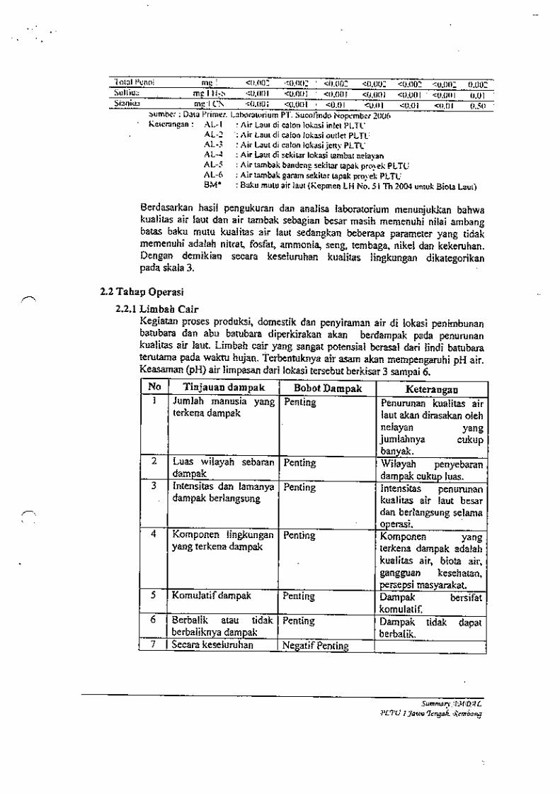
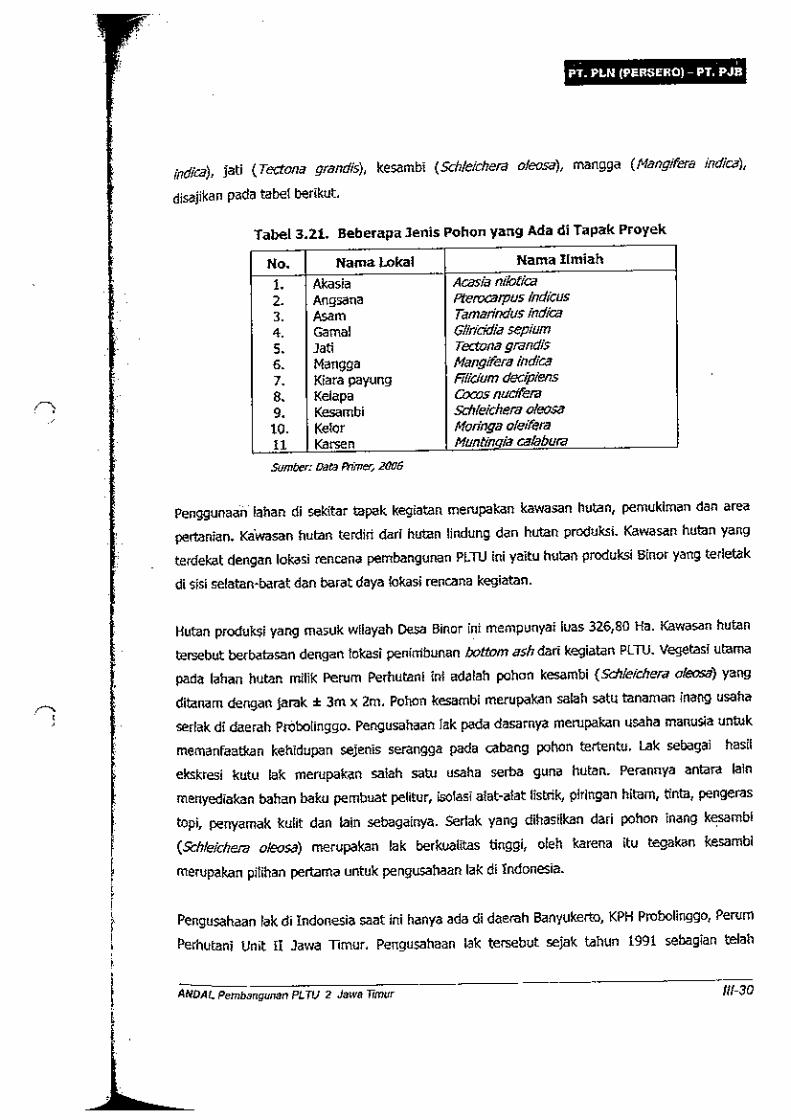
Based on the assumption mentioned above, Figure-1 shows the optimal bank combination calculated experimentally. From this experiment result, Bank combination of 100MVA, 3 banks should be recommended in heavy demand density area and on the other hand smaller bank combination should be recommended in light demand density area.
Demand Density (MVA/km*2)
Figure-1 Optimal Bank Combination
10 9 8 7 6 5
4 3 2 1 0
0 50*2 100*2 100*3 Bank Capacity(MW)
Supply Area(km)
5 5 6 6 6 6
6 7 8 9 17
B. Mitigation Measure on Three Phase Short Circuit Fault Current Capacity
① System Division This method avoids the increase in short-circuit current by dividing the bus bar of the substation
or increasing the impedance of the system with the reduction of the number of loop lines of the transmission line. Though this measure has 2 systems, normal division and in-accident division, it is necessary to adopt these after ensuring the stability required, since either way leads to the degradation of the stability.
② System Division by Introduction of High Order Voltage In case short-circuit current in a system of a certain voltage class increases and comes to a dead
lock, voltage of one class higher is introduced as a main system, suppressing the short-circuit current by the division of the lower order system. Though this method is the most practical when harmonized with the future system expansion as it also contributes to the improvement of stability, the reorganization of the systems requires a huge investment so careful examination is necessary.
③ Division of AC system by DC Interconnection Moreover, this method might be adopted as a means of the short-circuit current control in the
future AC/DC transfer equipment is costly. ④ Adoption of High Impedance Equipment Raising the impedance of transformers, generators and so on effective in controlling the system
short-circuit current and advantageous in reducing the size and the production cost of the equipment. In the meantime, when raised above a certain level, it may require a special design involving higher cost, and disadvantages can result such as increase in reactive power loss and voltage fluctuation as well as deterioration of the stability of the system.
⑤ Adoption of Current-Limiting Reactor This a method of raising the impedance of the system, and there are two types; setting a serial
reactor in a transmission line and setting a shunt reactor after dividing the bus bar. Since the current always flows in the reactor in the former method, it is disadvantageous concerning loss, voltage adjustment, and stability, and there have been few cases, where this system has been adopted and therefore the latter system has usually been adopted.
**** Reference : Countermeasures for System Stability *************** To ensure stability, all generators connected with the electric power system must always operate at synchronous speed, providing stable electricity to the customers. In the situation where these generators cannot operate at synchronous speed (called step-out), the generators are unable to provide sufficient electricity for the load thus resulting in insufficient power. The ability to run the generators at this synchronous speed is called stability. Accordingly, good stability means a high capability of running the machines at synchronous speed. Stability is evaluated by phase-angle in the electric power system, and it can be calculated as below. When the angle is over 90 degrees, step-out results. Phase-angle=ΣK(active power of each point × reactance) K: Proportion constant In the actual system, transient stability problems arise, such as conditions in which the above mentioned shafts temporarily become extremely thin because of power line accidents, solving and

fixing these problems, or considering whether stability can be maintained despite external disturbances. For enhancing system Stability, the following Improvement Measures should be considered as required. SVR (STATCOM) : Adoption of High Capacity Transmission Line with Multi Bind Phase Conductor (1) Decrease of the systematic serial reactance in the system. If the serial reactance is decreased, stable electric power limit can be increased. The following outlines the various ways this can be done:
a. Increasing the number of conductors of transmission line. By introducing multi-conductor system and providing 2 to 4 power lines per one main line,
meaning equivalent to increasing the power line radius, stability improves since the reactance decreases by 20-40%.
(2) Serial Capacitor By using serial capacitors, stability can be improved since the reactance of the line is
compensated for. However, for the improvement of transient stability, it is necessary to re-insert serial capacitors immediately after removing the fault. Moreover, it is necessary to give consideration to some protective device after the compensation since serial capacitors can cause some abnormal phenomena such as ferroresonance, low frequency continuous oscillation and so on.
(3) Reactance Decrease of Serial Equipment such as Generators and Transformers The reactance of generators and transformers should be preferably small for stability reasons.
However, setting the reactance much lower than the standard value is difficult due to the price of the machine and the short-circuit capacity of the transformer.
(4) Installation of Intermediate Switching Stations The sections of lines which would be opened during cases of fault in transmission lines can be
made short. (5) Adoption of High-Speed AVR In an immediate response to the voltage fluctuation at generator terminals in accidents, it is
possible to improve the stability by rapidly increasing the excitation current, raising the induced voltage inside the generator and reinforcing the synchronizing power. By this, the dynamic stability during the leading power factor operation, an especially important problem relating to stability, is remarkably improved. However, while the adoption of high-speed and high-gain AVR can increase the synchronizing power, it has some characteristics that result in weakening the braking force, and there is even a possibility of generating a secondary disturbance by AVR depending on the operating conditions and the system configuration. As a countermeasure for this problem, a system is being developed in which the braking force is made to increase by inputting into AVR the stabilizing signals detected from the change of rotational speed and output of the generator, and it is called PSS (Power System Stabilizer).
(6) Intermediate Reactive Power Supplier Stability can be improved by installing reactive power suppliers at the middle points of
transmission lines therefore maintaining the voltage of those points.
(7) Immediate Removal of Trouble a. High-Speed Relay and Circuit Breaker The transient stability is improved by removing the trouble speedily since it can reduce the
acceleration energy of the generator. Figure 2-13 shows the effect of the length of duration of fault on the stability of the 2-line transmission line classified by the types of fault in operation.
The fault can be removed very speedily, within 70~80mS, from the important transmission lines.
b. High-Speed Automatic Reclosing System After circuit-breaking the faulty section of the line and then reclosing following adequate
dead time, it is possible to continue the power transmission under normal conditions again, provided the fault point arc has been extinguished. There are 2-line or loop-system 1-line 3-phase reclosing system as well as 2-line multi-phase and 1-line single-phase reclosing systems. The dead time is an important issue in this case, and from the standpoint of stability, the shorter the better, but in general, in 275kV systems or less, about 500mS is secured to ensure the insulation recovery of the fault point by means of ion dispersal. In the higher voltage systems, longer dead time is required. Especially the single-phase reclosing system is effective for the 1-line transmission line since it cuts off only the faulty phase in case of single-line ground fault and carries on exchanges of electric power using the sound 2-phases, keeping the synchronization. The multi-phase reclosing system is effective for the 2-line transmission line particularly in frequent cases of 2-line simultaneous failure. However, sufficient examination is required when adopting the reclosing protection for large-capacity turbine generators since excessive torque can be generated in the turbine shaft by failure in reclosing.
(8) Equilibration of Generator Input/Output in Disturbance
a. Braking Resistance Immediately after a case of fault, resistance can be inserted in the generator circuit in
parallel or in series so that energy is consumed and the imbalance of input and output of the generator is suppressed, preventing the acceleration of the generator and thus improving the transient stability.
b. High-Speed Valve Control Whereas the above braking resistance suppresses the imbalance on the output side of the
generator, as a countermeasure on the input side, transient stability can be improved by means of a steam bypass which reduces the amount of steam entering the turbine at high speed, thus preventing acceleration of the generator.
(9) DC Interconnection By the division of long-distance AC systems and operation of crossing series-parallel systems
using the DC interconnection facility, stability can be remarkably improved. (10) System Separation In case a step-out has already occurred partially or such a case is expected to occur due to fault in
a system, by appropriately separating the affected system, the stability of the remaining system can be ensured. Still, it is necessary to make decisions considering power flows and characteristics of the protective relay, etc. in the selection of the line separation point.
(11) Power Restriction and Load Restriction By speedily limiting a part of power and load, the acceleration of other generators and the abrupt
reduction of voltage can be prevented, thus securing stability.

************** Reference : Upgrading Planning for. Distributing Substation **************
1. Basic matters (1) Standards of upgrading period Distribution substations are upgraded when the overall utilization factor of the target group
exceeds 95%. The utilization factor of each substation in the target group must be kept below 100%. But, if there are special circumstances regarding importance of loads, distribution switching capability and overload unit of equipment, and in case of measures for Voltage, consideration mast be given to individual cases.
(2) Upgrading process In principle, priority must be given to construction of new substations when the average
(supply area of the target group is larger than the appropriate supply area and to line improvement When the average Supply area of the target group is smaller than the appropriate supply area. But, if there is one-bank substation _in the target group, the decision must be made based on cost accounting of that substation, or in such cases where individual conditions have particular factors such as distribution switching capability and in such regions where appropriate areas can hardly be defined (regions with load density of higher than 24MW/km2 or lower than 1.5MW/km2), the decision must be made based on cost accounting of individual cases.
[Average supply area < Appropriate supply area < Average supply area | |
Line improvement construction of new substation
(3) Procedures for consideration of upgrading process - Consideration of upgrading process must follow the procedures shown in the Figure-2. Specific procedures must be considered according to rV.2-(5).
Note 1 : Overall group utilization factor of distributing substations continuous overload limit of transformer 113%
Error of assumed demand -8% Diversity factor between banks -5%
utilization factor limit of substation 100% Lump ratio of distribution -5% overall group utilization factor 95%

APPENDIX-8 OUTLINE OF PSS/E SOFTWARE

Appendix 8 : Outline of PSS/E software PSS/E (Power system Simulation for Engineering) is the program, of which authorized distributor is SIEMENS/PTI, and widely used by power network expert in many countries, such as Malaysia and China. The newest version of PSS/E is Ver.30 released in September 2004 and introducing an entirely new GUI. PSS/E provides the following functions which covers all analyses to be done under the TOR;
Load flow analysis Short circuit current analysis Nominal state stability analysis Transient stability analysis Voltage stability analysis
Concerning hardware, we are tentatively considering the following configuration to run the above software.

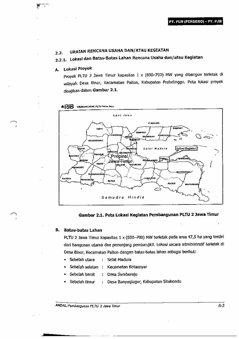
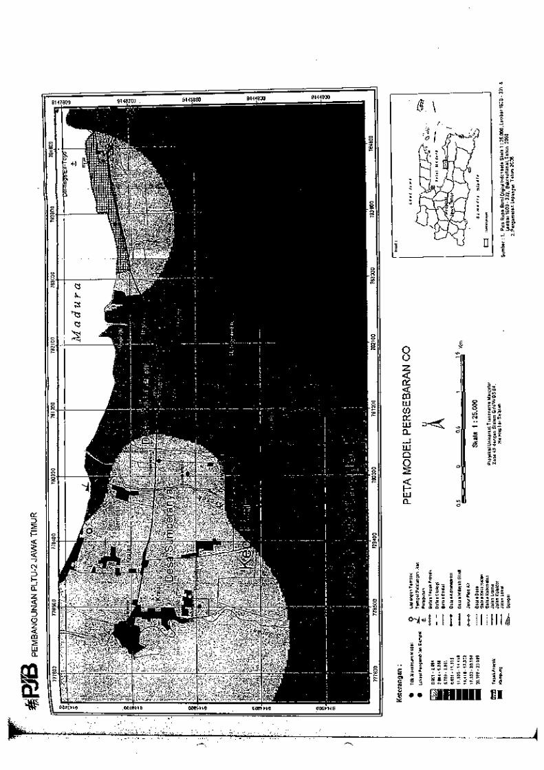
APPENDIX-9 “ANALISIS DAMPAK LINGKUNGAN (ANDAL)
PEMBANGUNAN PEMBANGKIT LISTRIK TENAGA UAP (PLTU) 2 JAWA TIMUR KAPASITAS 1 × (600-700) MW
DI KABUPATEN PROBOLINGGO”


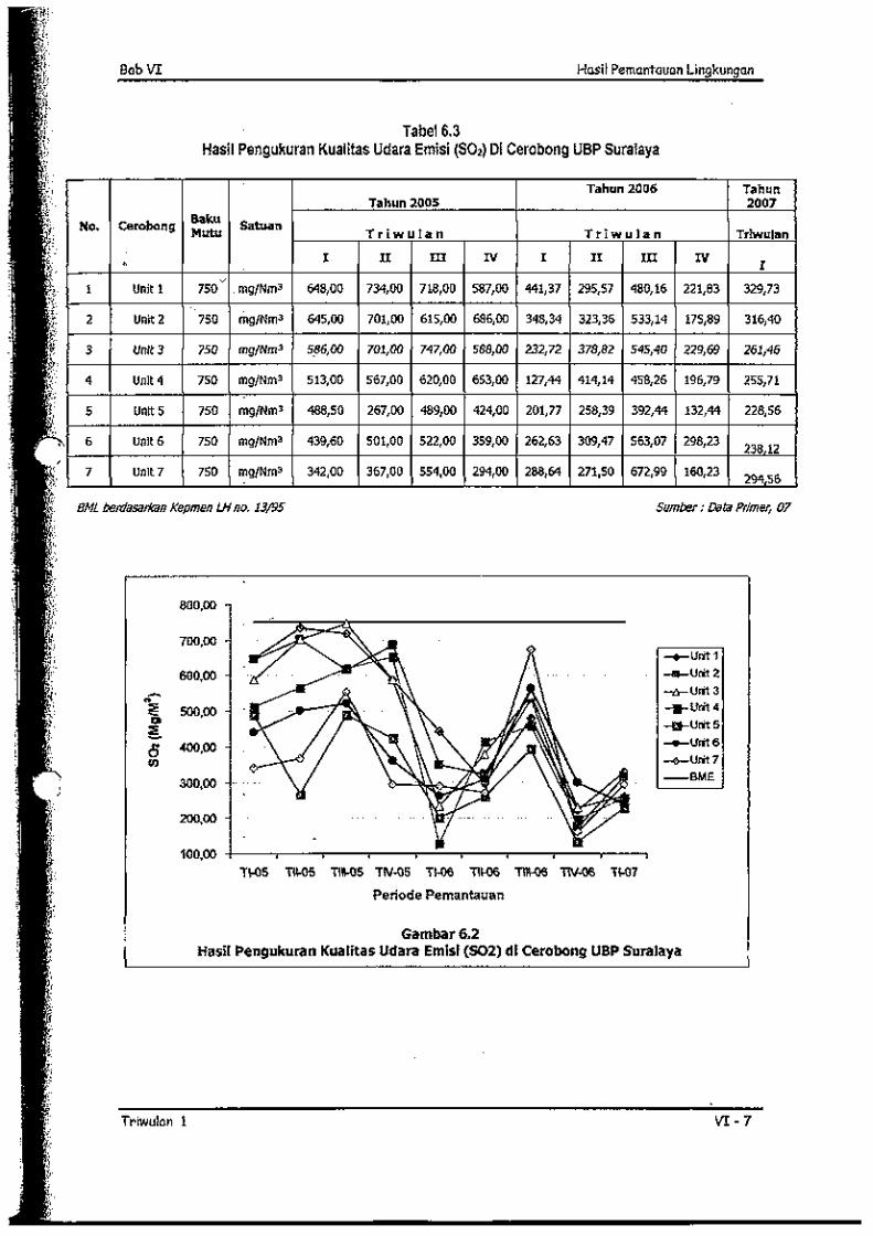
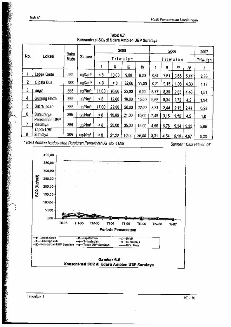
APPENDIX-10 “PEMANTAUAN PELAKSANAAN RKL DAN RPL PLTU SURALAYA UNIT 1-8 SEMESTER 1 TAHUN 2007”


APPENDIX-11 “NOTA DINAS NO. 062/121/PD Y5/2008” FOR
SUMMARY AMDAL PLTU1 JAWA TENGAH REMBANG