appendix 3h auxiliary and shield building critical sections
TRANSCRIPT
*NRC Staff approval is required prior to implementing a change in this information.
3H-1 Revision 7
VEGP 3&4 – UFSAR
Appendix 3H Auxiliary and Shield Building Critical Sections
3H.1 Introduction
[This appendix summarizes the structural design and analysis of structures identified as "Critical Sections" in the auxiliary and shield buildings. The design summaries include the following information:
Description of buildings
Governing codes and regulations
Structural loads and load combinations
Global analyses
Structural design of critical structural elements
Subsections 3H.2 through 3H.5 include a general description of the auxiliary building and shield building, a summary of the design criteria and the global analyses. The 3H.5 figures referenced in the descriptions show the structural designs for critical sections which are identified in subsection 3H.5 and shown in Figure 3H.5-1 (3 sheets). The exact locations of the critical sections related to the shield building cylinder are shown in Figure 3H.5-16. Representative design details are provided for these structures in subsection 3H.5.]*
3H.2 Description of Auxiliary and Shield Buildings
3H.2.1 Description of Auxiliary Building
[The auxiliary building is a reinforced concrete structure. The auxiliary building is one of the three buildings that make up the nuclear island and shares a common basemat with the containment building and the shield building. The auxiliary building general layout is shown in Figure 3H.2-1. It is a C-shaped section of the nuclear island that wraps around approximately half of the circumference of the shield building. The building dimensions are shown on key structural dimension drawings, Figure 3.7.2-12.
The auxiliary building is divided into six areas, which are identified in Figure 3H.2-1. It is a 5-story building; three stories are located above grade and two are located below grade. Areas 1 and 2 (Figure 3H.2-1) have five floors, including two floors below grade level. The lowest floor at elevation 66′-6″ is used exclusively for housing battery racks. The next higher floor, at elevation 82′-6″, also has battery racks and some electrical equipment. The floor at the grade level, elevation 100′-0″, has electrical penetration areas, a remote shutdown workstation room, motor control centers, and some Division A and Division C equipment. The main control room is situated on the floor at elevation 117′-6″, which also has rooms for the main steam and feedwater lines. The floor at elevation 135′-3″ carries air filtration and air handling units, chiller pump equipment, and other mechanical and electrical equipment. The roof for areas 1 and 2 is at elevation 153′-0″.
Areas 3 and 4 of the auxiliary building are the areas east of the containment shield building. Valve and piping areas, and some mechanical equipment, are located in the basement floor at elevation 66′-6″. The floor at elevation 82′-6″ has a piping penetration area, a radiation chemistry laboratory, makeup pumps, and other mechanical equipment. The floor at grade level elevation 100′-0″ has an electrical penetration room, a staging area for the equipment hatch, and the access opening to the annex building. The electrical penetration area, trip switchgears, and other electrical equipment occupy most of the floor at elevation 117′-6″. The floor at elevation 135′-3″ is used for the
*NRC Staff approval is required prior to implementing a change in this information.
3H-2 Revision 7
VEGP 3&4 – UFSAR
storage of main control room air cylinders and provides access to the annex building. The roof for these areas is at elevation 160′-6″.
Areas 5 and 6 include facilities for storage and handling of new and spent fuel. The spent fuel pool, fuel transfer canal, and cask loading and cask washdown pits have concrete walls and floors. They are lined on the inside surface with stainless steel plate for leak prevention. Interior structural walls and major floors are constructed using concrete filled steel plate modules, steel form modules, or reinforced concrete. The new fuel storage area is a separate reinforced concrete pit providing temporary dry storage for the new fuel assemblies. A 150-ton cask handling crane travels in the east-west direction. The location and travel of this crane prevents the crane from carrying loads over the spent fuel pool to preclude them from falling into the spent fuel pool. Mechanical equipment is also located in this area for spent fuel cooling, residual heat removal, and liquid waste processing. This equipment is generally nonsafety-related.]*
3H.2.2 Description of Shield Building
The shield building is the structure and annulus area that surrounds the containment building. It shares a common basemat with the containment building and the auxiliary building. The shield building uses concrete-filled steel plate construction (SC) as well as reinforced concrete (RC) structure. The figures in Section 1.2 show the layout of the shield building and its interface with the other buildings of the nuclear island.
Figure 3.8.4-5 shows the following significant features and the principal systems and components of the shield building:
Shield building cylindrical structure Shield building roof structure RC/SC connections Air inlets and tension ring Knuckle region (connection to exterior wall of PCS tank) Compression ring (connection to interior wall of PCS tank) Passive containment cooling system (PCS) water storage tank (PCCWST)
The overall configuration of the shield building is established from functional requirements related to radiation shielding, missile barrier, passive containment cooling, tornado, and seismic event protection. These functional requirements led to establishing the design based on two primary design codes used for nuclear plant structures: 1) ACI 349 for reinforced concrete design, and 2) ANSI/AISC N690 for structural steel design.
The shield building SC walls are anchored to the RC basemat and shield building RC wall by mechanical connections. These RC-to-SC connections are also used in the other regions of the shield building, including:
Auxiliary building RC roof connection to the shield building SC wall Auxiliary building RC wall connection to shield building SC wall Tension ring connection to the shield building RC roof
The connections provide for the direct transfer of forces from the RC reinforcing steel to the SC liner plates.
The cylindrical shield wall has an outside radius of 72.5 feet and a thickness of 36 inches. The cylindrical wall section that is a few feet below the auxiliary building roof line is a reinforced concrete (RC) structure. The section that is not protected by the auxiliary building is a steel concrete (SC) composite structure (see Figure 3H.5-16). The overall thickness of 36 inches is the same as the RC
3H-3 Revision 7
VEGP 3&4 – UFSAR
wall below. The concrete for the SC portion is standard concrete with compressive strength of 6000 psi. The SC portion is constructed with steel surface plates, which act as concrete reinforcement. The 0.75-inch tie bars are welded to the steel faceplates to develop composite behavior of the steel faceplates and concrete. The shear studs are welded to the inside surface of the steel plate. The tie bar spacing is reduced in the higher stress regions. A typical SC wall panel is shown in Figure 3H.5-13.
The tension ring is located at the interface of the shield building steel concrete composite air inlet structures and the shield building reinforced concrete roof. The top of the tension ring interfaces with the RC roof slab. The tension ring supports the roof girders that are located under the RC roof slab. The bottom of the tension ring is attached to the air inlets structure. The bottom of the air inlets structure is attached to the top of the cylindrical SC wall of the shield building. The connection of the tension ring to the roof is a mechanical connection design and is described above.
The primary function of the tension ring is to resist the thrust from the shield building roof. The air inlets structure is located directly below the tension ring and includes the air openings that provide for natural circulation of cooling air. Though its steel plates are connected to the concrete infill by studs and tie bars, the tension ring is conservatively designed as a hollow steel box girder. The concrete infill is credited only for out-of-plane shear transfer and for stability of the steel plates. The tension ring is designed to have high stiffness and to remain elastic under required load combinations.
The air inlets structure is a 4.5-foot-thick SC structure with through-wall openings for air flow. The air inlet openings consist of circular pipes at a downward inclination of 38 degrees from the vertical. Steel plates on each face, aligned with the inner and outer flanges of the tension ring, serve as primary reinforcement. The concrete infill is connected to the steel plates with tie bars and studs. The top of the air inlets structure is welded to the underside of the tension ring. The bottom of the air inlets structure is welded to the SC wall.
The shield building conical roof steel structure consists of 32 radial beams. Between each pair of radial beams there are circumferential beams. A steel plate is welded to the top flanges of each beam and forms a surface on which the concrete is placed. The steel structure forms a conical shell that spans the area from the compression ring to the tension ring.
The outside diameter of the PCS tank (passive containment cooling water storage tank) intersects with the shield building roof at the knuckle region. Outside of the PCS tank, the concrete roof slab thickness is 3 feet and at the bottom of the PCS tank, the concrete thickness is 2 feet. The wall from the PCS tank applies a load to the roof slab, and also provides stiffness and increases the strength of the roof in that region.
The inside diameter of the PCS tank intersects with the roof slab at the compression ring. The compression ring provides the compression support for the conical roof dome. It consists of a composite structure having a curved steel beam section, which supports the concrete roof directly above it. The inside wall of the PCS tank is located above the concrete roof. Studs are placed on the top flange of the steel girder to allow the steel and concrete sections to act as a composite unit. The curved girder is designed to provide support for the steel structure during construction and during the initial placement of the concrete roof before the concrete has hardened sufficiently.
The PCS tank sits on top of the shield building roof. It is supported by and acts integrally with the conical roof. The inside surface has a liner that functions to provide leak protection, but is not required to provide structural strength to the structure. Leak chase channels are provided over the liner welds. The top elevation of the water inside the tank for the PCS has sufficient freeboard to preclude impact on the roof during the SSE.
*NRC Staff approval is required prior to implementing a change in this information.
3H-4 Revision 7
VEGP 3&4 – UFSAR
3H.3 Design Criteria
[The auxiliary and shield building structures are reinforced concrete structures, structural modules, and horizontal concrete slabs supported by composite structural steel framing.
Seismic forces are obtained from the response spectrum analysis of the three-dimensionalfinite element analysis models as described in subsection 3H.4. The shear wall and floor slabdesign also considers out-of-plane bending and shear forces due to loading, such as liveload, dead load, seismic, lateral earth pressure, hydrostatic, hydrodynamic, and windpressure.
The shield building roof and the passive containment cooling water storage tank are analyzedusing three-dimensional finite element models with the ANSYS computer code]* as describedin subsection 3.8.4.4.1. [Loads and load combinations include construction, dead, live,thermal, wind, and seismic. The response spectrum analysis of the nuclear island issupplemented by equivalent static acceleration analysis of a more detailed model of aquadrant of the shield building roof. The results from the more detailed analysis are used inthe evaluation of the tension ring, air inlets, and radial beams. The seismic response of thewater in the tank is analyzed in a separate analysis with seismic input defined by the floorresponse spectrum.
The structural steel framing is used primarily to support the concrete slabs and roofs. Metaldecking, supported by the steel framing, is used as form work for the concrete slabs androofs.
The finned floors for the main control room and the instrumentation and control room ceilingsare designed as reinforced concrete slabs in accordance with American Concrete Institutestandard ACI 349. The steel panels are designed and constructed in accordance withAmerican Institute of Steel Construction Standard AISC N690. For positive bending, the steelplate is in tension and the steel plate with fin stiffeners serves as the bottom reinforcement.For negative bending, compression is resisted by the stiffened plate and tension by topreinforcement in the concrete.]*
3H.3.1 Governing Codes and Standards
[The primary codes and standards used in the design of the auxiliary and shield buildings are listed below:
ACI 349-01, "Code Requirements for Nuclear Safety Related Concrete Structures" (refer toSubsection 3.8.4.5 for supplementary requirements and Subsection 3.8.4.4.1 for alternativerequirements).
ANSI/AISC N690-1994, "Specification for the Design, Fabrication and Erection ofSafety-Related Steel Structures for Nuclear Facilities" (refer to subsection 3.8.4.5 forsupplemental requirements). American Welding Society (AWS), Structural Welding Code -Steel, AWS D1.1-2000 provides an acceptable alternative for AISC N690 weld requirements asdescribed in Subsections 3.8.3.2 and 3.8.4.2.]*
3H.3.2 Seismic Input
The SSE design response spectra are given in Figures 3.7.1-1 and 3.7.1-2. [They are based on the Regulatory Guide 1.60 response spectra anchored to 0.30g, but are amplified at 25 Hertz to reflect larger high-frequency seismic energy content observed for eastern United States sites.]* The nuclear island seismic analyses are summarized in Subsection 3.7.2.

*NRC Staff approval is required prior to implementing a change in this information.
3H-5 Revision 7
VEGP 3&4 – UFSAR
3H.3.3 Loads
[The auxiliary and shield buildings are seismic Category I structures. The loads listed in the following subsections are used for the design of the building structures. All the listed loads are not necessarily applicable to all structures and their elements. Loads for which each structural element is designed are based on the conditions to which that particular structural element is potentially subjected.]*
Dead Load (D):
[The weight of all permanent construction and installations, including fixed equipment, is included as the dead load during its normal operating condition.
The weight of minor equipment (not specifically included in the dead load), piping, cables and cable trays, ducts, and their supports was included as equivalent dead load (EDL). A minimum of 50 pounds per square foot (psf) was used as EDL. For floors with a significant number of small pieces of equipment, the total weight of miscellaneous small pieces of equipment, divided by the floor area of the room plus an additional 50 psf was used as the equivalent dead load.]*
Earth Pressure (H):
[The static earth pressure acting on the structures during normal operation is considered in the design of exterior walls. The dynamic soil pressure, induced during a safe shutdown earthquake (SSE), is included as a seismic load.]*
Live Loads (L):
[The load imposed by the use and occupancy of the building is included as the live load. Live loads include floor area loads, laydown loads, fuel transfer casks, equipment handling loads, trucks, railroad vehicles, and similar items. The floor area live load is not applied on areas occupied by equipment whose weight is specifically included in the dead load. Live load is applicable on areas under equipment where access is provided, for instance, the floor under an elevated tank supported on legs.
Floor loading diagrams are prepared for areas for component laydown. The diagrams show the location of major pieces of equipment and their foot-print loads or equivalent uniformly distributed loads.
The following live load items are considered in design:
A. Building floor loads
The following minimum values for live loads are used.
– Structural platforms and gratings 100 psf
– Ground floors 250 psf
– All other elevated floors 200 psf(This load is reduced if the equivalent dead load for the floor is more than 50 psf. The sum of the live load and the equivalent dead load is 250 psf.)

*NRC Staff approval is required prior to implementing a change in this information.
3H-6 Revision 7
VEGP 3&4 – UFSAR
B. Roof loads
The roof is designed for a uniform snow load of 63 psf calculated in accordance with ASCE 7-98. This corresponds to ground snow load of 75 psf, exposure factor of 1.0, thermal factor of 1.0, and an importance factor of 1.2.
C. Concentrated loads for the design of local members
In design reconciliation analysis, if actual loads are established to be lower than the above loads, the actual loads are used for reconciliation.
D. Temporary exterior wall surcharge
When applicable, a minimum surcharge outside and adjacent to subsurface wall of 250 psf is applied.
E. Construction loads
The additional construction loads produced by cranes, trucks, and the like, with their pickup loads, are considered. For steel beams supporting concrete floors, the weight of the wet concrete plus 100 psf uniform load and 5,000 pounds concentrated load, distributed near points of maximum shear and moment, is applied. A one-third increase in allowable stress is permitted.
Metal decking and precast concrete panels, used as formwork for concrete floors are designed for the wet weight of the concrete plus a construction live load of 20 psf uniform or 150 pounds concentrated. The deflection during normal operation is limited to span in inches divided by 180, or 0.75 inch, whichever is less.
F. Crane loads
The impact allowance for traveling crane supports and runway horizontal forces is in accordance with AISC N690.
G. Elevator loads
The impact allowance used for the elevator supports is 100 percent, applied to design capacity and weight of car plus appurtenances, unless otherwise specified by the equipment supplier.
H. Equipment laydown and major maintenance
Floors are designed for planned refueling and maintenance activities as defined on equipment laydown drawings.]*
– Concentrated load on beams andgirders (in load combinations thatdo not include seismic load)
5,000 pounds so applied as to maximize moment or shear. This load is not carried to columns or walls. It is not applied in areas where no heavy equipment will be located or transported, such as the access control areas.
– Concentrated load on slabs(considered with dead load only)
5,000 pounds so applied as to maximize moment or shear. This load is not carried to columns or walls. It is not applied in access control areas.
*NRC Staff approval is required prior to implementing a change in this information.
3H-7 Revision 7
VEGP 3&4 – UFSAR
Wind Load
[The wind loads are as follows:
Design wind (W)
For the design of the exterior walls, wind loads are applied in accordance with ASCE 7-98 with a basic wind speed of 145 mph. The importance factor is 1.15, and the exposure category is C. Wind loads are not combined with seismic loads.
Tornado load (Wt)
The exterior walls of the auxiliary and shield buildings are designed for tornado. A maximum wind speed of 300 mph (maximum rotational speed: 240 mph, maximum translational speed: 60 mph) is used to design the structures.]*
Seismic Loads (Es)
[The SSE (Es) is used for evaluation of the structures of the auxiliary and shield buildings. Es is defined as the loads generated by the SSE specified for the plant, including the associated hydrodynamic loads and dynamic incremental soil pressure.]*
Operating Thermal Loads (To)
[Normal thermal loads for the exterior walls and roofs are addressed in the design. These correspond to positive and negative linear temperature gradients with the inside surface at an average 70°F and the outside air temperature at -40°F and +115°F, respectively. These loads are considered for the seismic Category I structures in combination with the SSE also. All exterior walls of the nuclear island above grade not protected by adjacent buildings are designed for these thermal loads. The thermal gradient is also applied to the portion of the shield building between the upper annulus and the auxiliary building.
Normal thermal loads for the passive containment cooling system (PCS) tank design are calculated based on the outside air temperature extremes specified for the safety-related design. The PCS tank is assumed to be at 40°F when the outside air temperature is -40°F. The water in the PCS tank is assumed to be at 70°F when the outside air temperature is postulated to be at 115°F.
Normal thermal loads due to a thermal gradient in the structures below the grade level (exterior walls and basemat) are small and are not considered in the design.]*
Effects of Pipe Rupture (Y)
[The evaluations consider the following loads:
Accident design pressure load, Pa, within or across a compartment and/or building generated by the postulated pipe rupture, including the dynamic effects due to the pressure time history.
Main steam isolation valve (MSIV) and steam generator blowdown valve compartments are designed for a pressurization load of 6 pounds per square inch (psi).
Accident thermal loads, Ta, due to thermal conditions generated by the postulated pipe break and including To.
Temperature gradients are based on an exterior air temperature of -40°F.

*NRC Staff approval is required prior to implementing a change in this information.
3H-8 Revision 7
VEGP 3&4 – UFSAR
The structural integrity of the west wall of the main control room is also evaluated for the jet impingement (Yj)]*
3H.3.4 Load Combinations and Acceptance Criteria
[Concrete structures are designed in accordance with ACI 349 for the load combinations and load factors given in Table 3.8.4-2. Steel structures are designed in accordance with AISC N690 for the load combinations and stress limit coefficients given in Table 3.8.4-1. The following supplemental requirements are applied for the use of AISC N690:
In Section Q1.0.2, the definition of secondary stress applies to stresses developed bytemperature loading only.
In Section Q1.3, where the structural effects of differential settlement are present, they areincluded with the dead load, D.
In Table Q1.5.7.1, the stress limit coefficients for compression are as follows:
– 1.3 instead of 1.5 in load combinations 2, 5, and 6
– 1.4 instead of 1.6 in load combinations 7, 8, and 9
– 1.6 instead of 1.7 in load combination 11
In Section Q1.5.8, for constrained members (rotation and/or displacement constraint suchthat a thermal load causes significant stresses) supporting safety-related structures, systems,or components, the stresses under load combinations 9, 10, and 11 are limited to thoseallowed in Table Q1.5.7.1 as modified above.]*
3H.4 Seismic Analyses
[A global seismic analysis of the AP1000 nuclear island structure is performed to obtain building seismic response for the seismic design of nuclear safety-related structures. The seismic loads for the design of the shear walls and the slabs in the auxiliary building are based on a response spectrum analysis of the auxiliary building and the shield building 3D finite element models.]* This analysis is described in Subsection 3.7.2. [For determining the out-of-plane seismic loads on flexible slabs and wall segments, spectral accelerations are obtained from time history analyses or from the relevant response spectra, using the 7 percent damping curve. Hand calculations are performed to estimate the out-of-plane seismic forces and the corresponding bending moment in each shear wall and floor slab element to supplement the loads obtained from the global seismic analysis.]*
3H.4.1 Live Load for Seismic Design
[Floor live loads, based on requirements during plant construction and maintenance activities, are specified varying from 50 to 250 pounds per square foot.
For the local design of members, such as the floors and beams, seismic loads include the response due to masses equal to 25 percent of the specified floor live loads or 75 percent of the roof snow load, whichever is applicable. These seismic loads are combined with 100 percent of the specified live loads, or 75 percent of the roof snow load, whichever is applicable. These live and snow loads are included as mass in calculating the vertical seismic forces on the floors and roof. The mass of equipment and distributed systems is included in both the dead and seismic loads.]*
*NRC Staff approval is required prior to implementing a change in this information.
3H-9 Revision 7
VEGP 3&4 – UFSAR
3H.5 Structural Design of Critical Sections
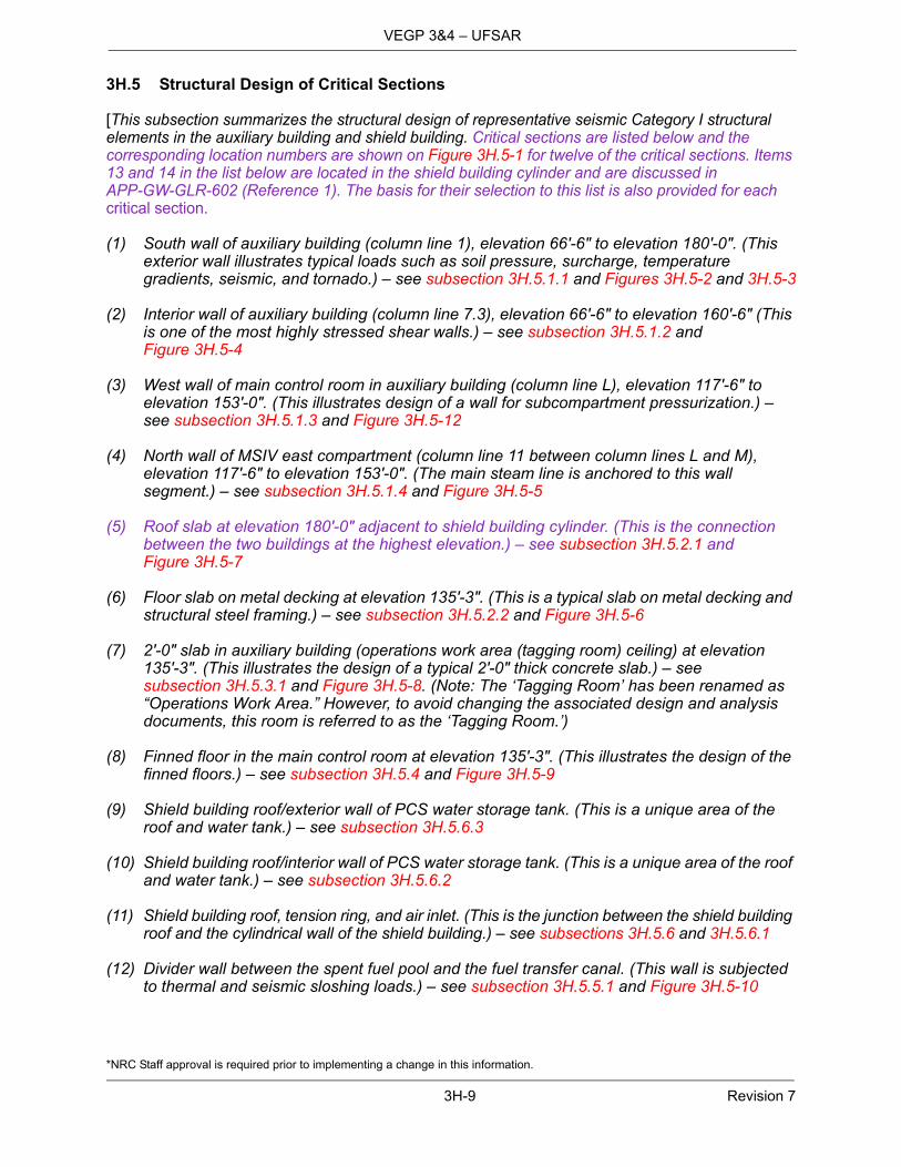
[This subsection summarizes the structural design of representative seismic Category I structural elements in the auxiliary building and shield building. Critical sections are listed below and the corresponding location numbers are shown on Figure 3H.5-1 for twelve of the critical sections. Items 13 and 14 in the list below are located in the shield building cylinder and are discussed in APP-GW-GLR-602 (Reference 1). The basis for their selection to this list is also provided for each critical section.
(1) South wall of auxiliary building (column line 1), elevation 66′-6″ to elevation 180′-0″. (This exterior wall illustrates typical loads such as soil pressure, surcharge, temperature gradients, seismic, and tornado.) – see subsection 3H.5.1.1 and Figures 3H.5-2 and 3H.5-3
(2) Interior wall of auxiliary building (column line 7.3), elevation 66′-6″ to elevation 160′-6″ (This is one of the most highly stressed shear walls.) – see subsection 3H.5.1.2 and Figure 3H.5-4
(3) West wall of main control room in auxiliary building (column line L), elevation 117′-6″ to elevation 153′-0″. (This illustrates design of a wall for subcompartment pressurization.) – see subsection 3H.5.1.3 and Figure 3H.5-12
(4) North wall of MSIV east compartment (column line 11 between column lines L and M), elevation 117′-6″ to elevation 153′-0″. (The main steam line is anchored to this wall segment.) – see subsection 3H.5.1.4 and Figure 3H.5-5
(5) Roof slab at elevation 180′-0″ adjacent to shield building cylinder. (This is the connection between the two buildings at the highest elevation.) – see subsection 3H.5.2.1 and Figure 3H.5-7
(6) Floor slab on metal decking at elevation 135′-3″. (This is a typical slab on metal decking and structural steel framing.) – see subsection 3H.5.2.2 and Figure 3H.5-6
(7) 2′-0″ slab in auxiliary building (operations work area (tagging room) ceiling) at elevation 135′-3″. (This illustrates the design of a typical 2′-0″ thick concrete slab.) – see subsection 3H.5.3.1 and Figure 3H.5-8. (Note: The ‘Tagging Room’ has been renamed as “Operations Work Area.” However, to avoid changing the associated design and analysis documents, this room is referred to as the ‘Tagging Room.’)
(8) Finned floor in the main control room at elevation 135′-3″. (This illustrates the design of the finned floors.) – see subsection 3H.5.4 and Figure 3H.5-9
(9) Shield building roof/exterior wall of PCS water storage tank. (This is a unique area of the roof and water tank.) – see subsection 3H.5.6.3
(10) Shield building roof/interior wall of PCS water storage tank. (This is a unique area of the roof and water tank.) – see subsection 3H.5.6.2
(11) Shield building roof, tension ring, and air inlet. (This is the junction between the shield building roof and the cylindrical wall of the shield building.) – see subsections 3H.5.6 and 3H.5.6.1
(12) Divider wall between the spent fuel pool and the fuel transfer canal. (This wall is subjected to thermal and seismic sloshing loads.) – see subsection 3H.5.5.1 and Figure 3H.5-10

*NRC Staff approval is required prior to implementing a change in this information.
3H-10 Revision 7
VEGP 3&4 – UFSAR
(13) Shield building SC cylinder is the exposed portions of the shield building that are not protected by the Auxiliary Building and is a steel concrete composite structure – see subsection 3H.5.7.1, Figure 3H.5-16, and Figures 5 and 6 of APP-GW-GLR-602 (Reference 1)
(14) Shield building SC to RC connection is the region of the shield building that anchors the SC cylindrical wall modules to the RC basemat and wall of the shield building – see subsection 3H.5.7.2, Figure 3H.5-16, and Figures 1, 2, and 3 of APP-GW-GLR-602 (Reference 1)
The design implemented in fabrication and construction drawings and instructions will have the design shown, an equal design, or a better design for the key structural elements.]*
3H.5.1 Shear Walls
Structural Description
[Shear walls in the auxiliary building vary in size, configuration, aspect ratio, and amount of reinforcement. The stress levels in shear walls depend on these parameters and the seismic acceleration level. The range of these parameters and the stress levels in various regions of the most severely stressed shear wall are described in the following paragraphs.
The height of the major structural shear walls in the auxiliary building ranges between 30 to 120 feet. The length ranges between 40 and 260 feet. The aspect ratio of these walls (full height/full length) is generally less than 1.0 and often less than 0.25. The walls are typically 2 to 5 feet thick, and are monolithically cast with the concrete floor slabs, which are 9 inches to 2 feet thick. Exterior shear walls are several stories high and do not have many large openings. Interior shear walls, however, are discontinuous in both vertical and horizontal directions. The in-plane behavior of these shear walls, including the large openings, is adequately represented in the analytical models for the global seismic response. Where the refinement of these finite element models is insufficient for design of the reinforcement, for example in walls with a large number of openings, detailed finite element models are used.
The shear walls are used as the primary system for resisting the lateral loads, such as earthquakes. The auxiliary building shear walls are also evaluated for flexure and shear due to the out-of-plane loads.]*
Design Approach
[The auxiliary building shear walls are designed to withstand the loads specified in subsection 3H.3.3. Beside dead, live, and other normal operating condition loads, the following loads are considered in the shear wall design:
Seismic loads
– The SSE loads for the wall are obtained from the seismic analyses of auxiliary/shield buildings that are described in subsection 3H.4.
– Calculations are performed by considering shear wall segments bounded by the floors below and above the segment and the adjacent walls perpendicular to, on both sides of, the segment under consideration. Appropriate boundary conditions are assumed for the four edges of the segment. Natural frequencies of wall segments are determined using finite element models or text book formulas for the frequency of plate structures. Corresponding spectral acceleration is determined from the applicable response spectrum.

*NRC Staff approval is required prior to implementing a change in this information.
3H-11 Revision 7
VEGP 3&4 – UFSAR
– Exterior walls, below grade level, are also evaluated for dynamic earth pressure exertedduring an SSE for two cases:
Dynamic earth pressure calculated in accordance with ASCE 4-98
Passive earth pressure
Accident pressure load
– Shear walls of the main steam isolation valves (MSIV) rooms are designed for 6 poundsper square inch (psi) differential pressure acting in conjunction with the seismic loads.Member forces due to accident pressure and SSE are combined by absolute sum.
– The main control room wall of the east MSIV compartment is evaluated for the pressureand the jet load due to a postulated main steamline break.
Tornado load
For exterior walls above grade level, tornado loads are considered.
The design temperatures for thermal gradient are included in Table 3H.5-1.
The shear walls are designed for the load combinations, as applicable, contained in Table 3.8.4-2. The wall sections are designed in accordance with the requirements of ACI 349-01.]*
3H.5.1.1 Exterior Wall at Column Line 1
[The wall at column line 1 is the exterior wall at the south end of the nuclear island. The reinforced concrete wall extends from the top of the basemat at elevation 66′-6″ to the roof at elevation 180′-0″. It is 3′-0″ thick below the grade. Above the grade, the wall thickness is as follows:
2′-3″, from column line I to 5′-7″ west of column line K-2, from elevation 100′-0″ to 109′-3″;
3′-0″, from 5′-7″ west of column line K-2 to column line N, from elevation 100′-0″ to 109′-3″;
2′-3″, from column line I to 5′-6″ east of column line L-2, from elevation 109′-3″ to 180′-0″;
3′-0″, from 5′-6″ east of column line L-2 to column line N, from elevation 109′-3″ to 125′-0″;
2′-3″, from 5′-6″ east of column line L-2 to column line N, from elevation 125′-0″ to 180′-0″.
The wall is designed for the applicable loads including dead load, live load, hydrostatic load, static and dynamic lateral soil pressure loads, seismic loads, and thermal loads. For various segments of this wall, Table 3H.5-2 provides the listing and magnitude of the various design loads and Table 3H.5-3 presents the details of the wall reinforcement. The sections where the required reinforcement is calculated are shown in Figure 3H.5-2 (Sheet 1). Typical wall reinforcement is shown on Figure 3H.5-3.]*
3H.5.1.2 Wall at Column Line 7.3
[The wall at column line 7.3 is a shear wall that connects the shield building and the nuclear island exterior wall at column line I. It extends from the top of the basemat at elevation 66′-6″ to the top of the roof. The wall is 3 feet thick below the grade at elevation 100′-0″ and 2 feet thick above the grade.

*NRC Staff approval is required prior to implementing a change in this information.
3H-12 Revision 7
VEGP 3&4 – UFSAR
Out-of-plane lateral support is provided to the wall by the floor slabs on either side of it and the roof at the top.
The auxiliary building design loads are described in Section 3H.3.3, and the wall is designed for the applicable loads.
For various segments of this wall, the corresponding governing load combination and associated design loads are shown in Table 3H.5-4. Table 3H.5-5 presents the details of the wall reinforcement. The sections where the required reinforcement is calculated are shown in Figure 3H.5-2 (Sheet 2). Typical wall reinforcement is shown on Figure 3H.5-4]*
3H.5.1.3 Wall at Column Line L
[The wall at column line L is a shear wall on the west side of the Main Control Room. It extends from the top of the basemat at elevation 66′-6″ to the top of the roof. The wall is 2 feet thick. Out-of-plane lateral support is provided to the wall by the floor slabs on either side of it and the roof at the top. The segment of the wall that is a part of the main control room boundary is from elevation 117′-6″ to elevation 135′-3″.
The auxiliary building design loads are described in subsection 3H.3.3, and the wall is designed for the applicable loads. In addition to the dead, live and seismic loads, the wall is designed to withstand a 6 pounds per square inch pressure load due to a pipe break in the MSIV room even though it is a break exclusion area. This wall segment is also designed to withstand a jet load due to the pipe break.
The governing load combination and associated design loads are those due to the postulated pipe rupture and are shown in Table 3H.5-6. Table 3H.5-7 and Figure 3H.5-12 present the details of the wall reinforcement. The sections where the required reinforcement is calculated are shown in Figure 3H.5-2 (Sheet 3).]*
3H.5.1.4 Wall at Column Line 11
[The north wall of the MSIV east compartment, at column line 11 (Wall 11) between elevation 117′-6″ and elevation 153′-0″, has been identified as a critical section.
The segment of the wall between elevation 117′-6″ and elevation 135′-3″ is 4 feet thick, and several pipes such as the main steam line, main feed water line, and the start-up feed water line are anchored to this wall at the interface with the turbine building.
The wall segment from elevation 135′-3″ to elevation 153′-0″ does not provide support to any high energy lines, and is 2 feet thick. This portion does not have to withstand reactions from high energy line breaks.
The wall (Wall 11) is designed to withstand loads such as the dead load, live load, seismic load and the thermal load. The MSIV compartments are break exclusion areas, but the design also considered the compartment pressurization load associated with a one square foot pipe rupture in the MSIV compartments. Wall 11 in the east MSIV compartment is also designed to withstand the jet loads and the reactions at the pipe anchors for main steam and main feedwater line breaks assumed to occur in the east MSIV compartment. Additionally, the Wall 11 design for both MSIV compartments considers loads from postulated breaks in the turbine building, which include turbine building first bay pressurization, jet loads, reactions at the Wall 11 pipe anchors, and pipe whip.
*NRC Staff approval is required prior to implementing a change in this information.
3H-13 Revision 7
VEGP 3&4 – UFSAR
The wall structure is analyzed using three dimensional finite element analyses supplemented by hand calculations. Analyses are performed for individual loads, and design loads are determined for applicable load combinations from Table 3.8.4-2.
Wall reinforcement for this location is shown in Figure 3H.5-5 illustrating conformance with ACI 349-01 requirements. The reinforcement detailing and development for the wall of the MSIV west compartment varies because the compartment is in the corner of the auxiliary building and the adjacent wall on column line Q (Wall Q) is oriented at 90 degrees to Wall 11.]*
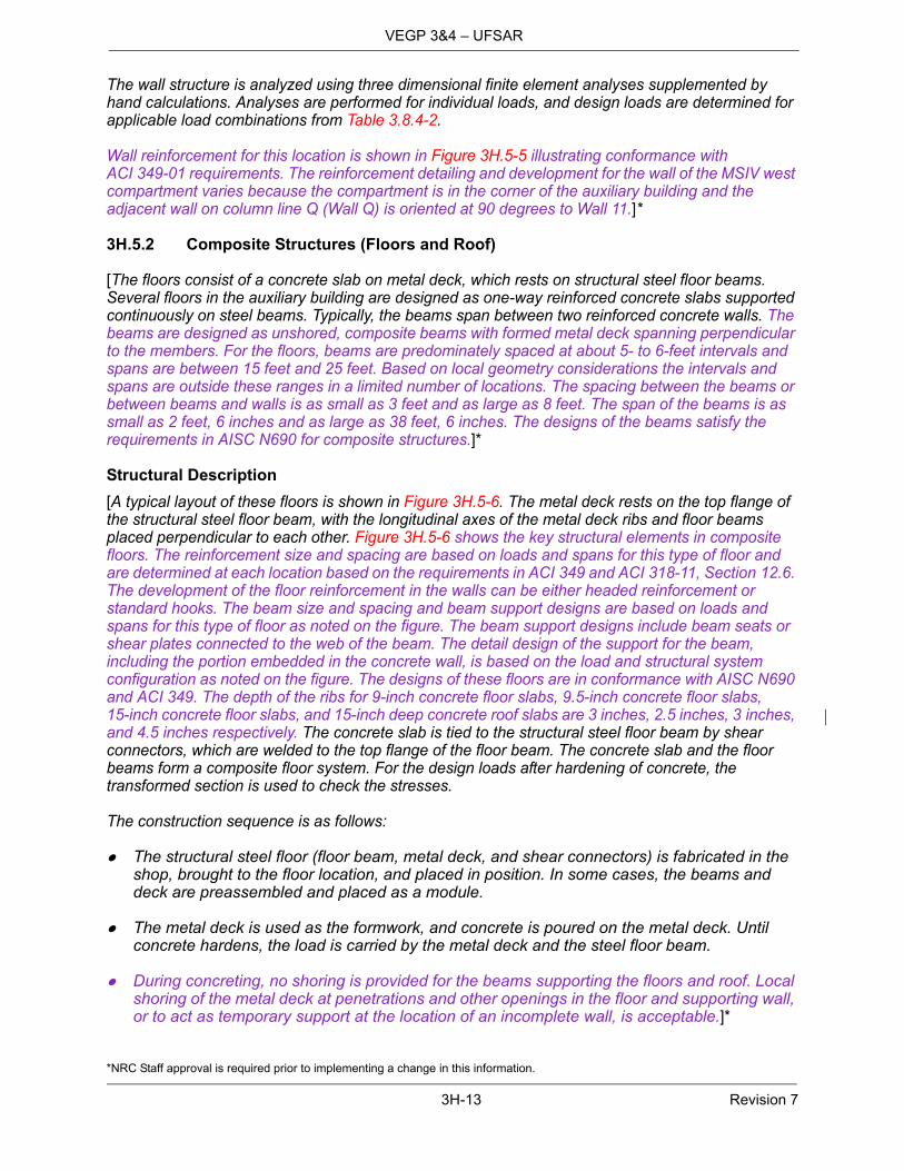
3H.5.2 Composite Structures (Floors and Roof)
[The floors consist of a concrete slab on metal deck, which rests on structural steel floor beams. Several floors in the auxiliary building are designed as one-way reinforced concrete slabs supported continuously on steel beams. Typically, the beams span between two reinforced concrete walls. The beams are designed as unshored, composite beams with formed metal deck spanning perpendicular to the members. For the floors, beams are predominately spaced at about 5- to 6-feet intervals and spans are between 15 feet and 25 feet. Based on local geometry considerations the intervals and spans are outside these ranges in a limited number of locations. The spacing between the beams or between beams and walls is as small as 3 feet and as large as 8 feet. The span of the beams is as small as 2 feet, 6 inches and as large as 38 feet, 6 inches. The designs of the beams satisfy the requirements in AISC N690 for composite structures.]*
Structural Description
[A typical layout of these floors is shown in Figure 3H.5-6. The metal deck rests on the top flange of the structural steel floor beam, with the longitudinal axes of the metal deck ribs and floor beams placed perpendicular to each other. Figure 3H.5-6 shows the key structural elements in composite floors. The reinforcement size and spacing are based on loads and spans for this type of floor and are determined at each location based on the requirements in ACI 349 and ACI 318-11, Section 12.6. The development of the floor reinforcement in the walls can be either headed reinforcement or standard hooks. The beam size and spacing and beam support designs are based on loads and spans for this type of floor as noted on the figure. The beam support designs include beam seats or shear plates connected to the web of the beam. The detail design of the support for the beam, including the portion embedded in the concrete wall, is based on the load and structural system configuration as noted on the figure. The designs of these floors are in conformance with AISC N690 and ACI 349. The depth of the ribs for 9-inch concrete floor slabs, 9.5-inch concrete floor slabs, 15-inch concrete floor slabs, and 15-inch deep concrete roof slabs are 3 inches, 2.5 inches, 3 inches, and 4.5 inches respectively. The concrete slab is tied to the structural steel floor beam by shear connectors, which are welded to the top flange of the floor beam. The concrete slab and the floor beams form a composite floor system. For the design loads after hardening of concrete, the transformed section is used to check the stresses.
The construction sequence is as follows:
The structural steel floor (floor beam, metal deck, and shear connectors) is fabricated in theshop, brought to the floor location, and placed in position. In some cases, the beams anddeck are preassembled and placed as a module.
The metal deck is used as the formwork, and concrete is poured on the metal deck. Untilconcrete hardens, the load is carried by the metal deck and the steel floor beam.
During concreting, no shoring is provided for the beams supporting the floors and roof. Localshoring of the metal deck at penetrations and other openings in the floor and supporting wall,or to act as temporary support at the location of an incomplete wall, is acceptable.]*

*NRC Staff approval is required prior to implementing a change in this information.
3H-14 Revision 7
VEGP 3&4 – UFSAR
Design Approach
[The floor design considers the dead, live, construction, extreme environmental, and other applicable loads identified in Section 3H.3.3. The design floor loading includes the equipment attached to the floor. The end condition for the steel beams is simply supported, or continuous. The seismic load is obtained using the applicable floor acceleration response spectrum (7 percent damping for the SSE loads).
The load combinations applicable to the design of these floors are shown in Tables 3.8.4-1 and 3.8.4-2. The design of the floor system is performed in two parts:
Design of structural steel beams
– The structural steel floor beams are evaluated to withstand the weight of wet concreteduring the placement of concrete. The composite section is designed for the design loadsduring normal and extreme environment conditions. Shear connectors are also designed.
Design of concrete slab
– The concrete slab and the steel reinforcement of the composite section are evaluated fornormal and extreme environmental conditions. The slab concrete and the reinforcement isdesigned to meet the requirements of American Concrete Institute standard ACI 349-01"Code Requirements for Nuclear Safety Related Concrete Structures."
– The slab design considers the in-plane and out-of-plane seismic forces. The globalin-plane and out-of-plane forces are obtained from the response spectrum analysis of the3D finite element model of the auxiliary and shield buildings. The out-of plane seismicforces due to floor self-excitation are determined by hand calculations using theapplicable vertical seismic response spectrum and slab frequency.]*
3H.5.2.1 Roof at Elevation 180′-0″, Area 6 (Critical Section is between Col. Lines N & K-2 and 3 & 4)
[The layout of this segment of the roof is shown in Figure 3H.5-7 as Region "B." The concrete slab is 15 inches thick, plus 4.5-inch deep metal deck ribs. It is composite with 4 feet deep plate girders by using shear connectors. The girder spacing is a range of 13′-0″ to 14′-2″ center to center. The girder flanges are 26″ x 2 1/2″ and the web is 43″ x 1″. The girders span approximately 64 feet in the north-south direction and are designed as simply supported. The concrete slab between the girders behaves as a one-way slab and is designed to span between the girders.
The roof girders are designed for dead and live loads, including construction loads (with wet concrete) with simple support end conditions. A one-third increase in allowable stress is permitted for the construction load combination.
The girders are also evaluated as part of the composite beam after drying of concrete. The composite roof structure is designed to withstand dead and live load / snow load, as well as the wind, tornado and seismic loads. The design summary for the critical section is shown in Table 3H.5-10. The design of the reinforcement and supporting beams, and girder and beam supports varies for other locations. The design is based on the loads and geometry for those sections.
A typical connection of the roof slab to the shield building is shown in Figure 3H.5-7. The figure shows the arrangement of reinforcement at the connection in the fuel building portion of the auxiliary building roof, the shield building cylindrical wall, and the walls of the auxiliary building just below the roof. The details of the connections between the auxiliary building roof and the shield building wall in other locations vary because of loads on the connection and the orientation of the wall to the roof

*NRC Staff approval is required prior to implementing a change in this information.
3H-15 Revision 7
VEGP 3&4 – UFSAR
reinforcement arrangement. These connection design details satisfy the requirements identified in Subsection 3.8.4.5.5.6.]*
3H.5.2.2 Floor at Elevation 135′-3″, Area 1 (Between Column Lines M and P)
[The design of a typical composite floor is shown in Figure 3H.5-6. The design summary for the floor between column lines M and P at elevation 135'-3'' is shown in Table 3H.5-11. The concrete slab is 9 inches thick, plus 3-inch deep metal deck ribs. The floor beam size is shown on the figure.
The floor beams are designed for construction load (with wet concrete) with simple supportend conditions. The design loads include the dead load and a construction live load of100 pounds per square foot (psf) distributed load plus 5000 pounds concentrated load nearthe point of maximum shear and moment. A one-third increase in allowable stress ispermitted.
The floor beams are also designed as part of the composite beam after drying of theconcrete. Because of continuity of rebars into the wall and the connection of the bottomflange to the support embedment, the end support condition is considered as fixed.]*
3H.5.3 Reinforced Concrete Slabs
[Reinforced concrete floors in auxiliary building are 24 inch or 36 inch thick. These floors are constructed with reinforced concrete placed on the top of 8 to 12 inch thick precast concrete panels. The precast concrete panels are installed at the bottom to serve as the formwork and withstand the load of wet concrete slab. The spans of the floors are predominately 13 feet to 20 feet, and the precast panels are predominately 7 to 14 feet wide. Based on local geometry considerations, the widths and spans are outside these ranges in a limited number of locations. The spans of the floor are as small as 5 feet and as large as 21 feet. The width of the precast panels is as small as 4 feet and as large as 19 feet. The number of side-by-side precast panels ranges from one to eight.
Examples of such floors are the Operations Work Area (Tagging Room) ceiling slab at elevation 135 ft 3 inches in Area 2, and the Area 5/6 elevation 100'-0'' slab between column lines 1 & 2.
Figure 3H.5-8 shows the key structural elements in reinforced concrete floor slabs. The precast panels and the cast-in-place concrete are designed to act together as a composite reinforced slab so that the floor dynamic response is consistent with the auxiliary building finite element analysis. However, the precast panels are neglected in determining floor strength and load carrying capacity. The reinforcement size and spacing are determined for each location, based on specific loads and spans, and satisfy the requirements in ACI 349 and ACI 318-11, Section 12.6. The floor thickness and precast panel thickness for this type of floor are based on specific loads and spans as noted on the figure. The type and thickness of adjacent walls and floors vary as noted on the figure. The main reinforcement is provided in the cast-in-place concrete. Reinforcement is placed in both the top and bottom layers of the cast-in-place concrete in both directions. For the design of the reinforcement in the cast-in-place floors, post-construction loads are conservatively assumed to be resisted only by the cast-in-place concrete and the reinforcement placed within it. The reinforcement in the cast-in-place portion is fully developed into supporting adjacent walls such that the connection is assumed to be a fixed connection. The development of the floor reinforcement in the walls is achieved using either headed reinforcement or standard hooks.
The precast panel reinforcement is designed to resist the weight of the panel and the wet weight of the cast-in-place concrete during construction. Reinforcement is placed within the precast panel portion in both top and bottom layers in both directions. The precast panel reinforcement is contained within the panel. The reinforcement is discontinuous with a design gap between adjacent precast panels and between precast panels and walls. The precast panels are connected to the concrete
*NRC Staff approval is required prior to implementing a change in this information.
3H-16 Revision 7
VEGP 3&4 – UFSAR
placed above them by shear reinforcement which satisfies the requirements of ACI 349 Chapter 17. The precast panels and the cast-in-place concrete are made to act together as a composite reinforced concrete slab by roughening the top surface of the precast panel and providing shear ties between the two elements. The detail designs of the supports for the precast panels are based on the loading and design requirements. The design of these floors is in conformance with AISC N690 and ACI 349.
The finite element analysis model used for the auxiliary building seismic response assumes a homogenous thickness of concrete for the floor system, and includes floor-to-wall connections that are fixed over the full thickness of the reinforced concrete floor. The detailed design of the floor system includes a gap between the precast panel and the wall and between adjacent precast panels. Although the gap between the precast panels and the wall reduces the thickness of the floor in direct contact with the wall, the design of the floor system satisfies the requirements of ACI 349, including fully developing the floor reinforcement in the wall. The design of the floor system and the connection with the wall provide a fixed connection that transfers forces and moments from the floor to the wall.
Detailed analysis of the floor system connection design details, including the gap between the precast panel and wall is performed for the floor constructed with precast panels and is consistent with the nuclear island seismic model. The effects of stiffness, reinforcement anchorage, and concrete cracking are considered in the detailed analyses. The detailed analyses demonstrate that these floors have vertical response above 33 Hz and are rigid, which is consistent with the nuclear island seismic model.]*
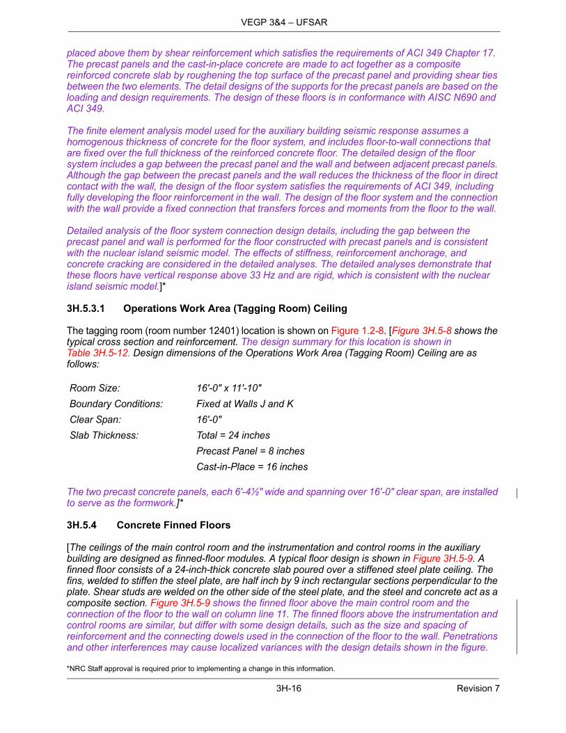
3H.5.3.1 Operations Work Area (Tagging Room) Ceiling
The tagging room (room number 12401) location is shown on Figure 1.2-8. [Figure 3H.5-8 shows the typical cross section and reinforcement. The design summary for this location is shown in Table 3H.5-12. Design dimensions of the Operations Work Area (Tagging Room) Ceiling are as follows:
The two precast concrete panels, each 6′-4½″ wide and spanning over 16′-0″ clear span, are installed to serve as the formwork.]*
3H.5.4 Concrete Finned Floors
[The ceilings of the main control room and the instrumentation and control rooms in the auxiliary building are designed as finned-floor modules. A typical floor design is shown in Figure 3H.5-9. A finned floor consists of a 24-inch-thick concrete slab poured over a stiffened steel plate ceiling. The fins, welded to stiffen the steel plate, are half inch by 9 inch rectangular sections perpendicular to the plate. Shear studs are welded on the other side of the steel plate, and the steel and concrete act as a composite section. Figure 3H.5-9 shows the finned floor above the main control room and the connection of the floor to the wall on column line 11. The finned floors above the instrumentation and control rooms are similar, but differ with some design details, such as the size and spacing of reinforcement and the connecting dowels used in the connection of the floor to the wall. Penetrations and other interferences may cause localized variances with the design details shown in the figure.
Room Size: 16′-0″ x 11′-10″
Boundary Conditions: Fixed at Walls J and K
Clear Span: 16′-0″
Slab Thickness: Total = 24 inches
Precast Panel = 8 inches
Cast-in-Place = 16 inches

*NRC Staff approval is required prior to implementing a change in this information.
3H-17 Revision 7
VEGP 3&4 – UFSAR
The fins are exposed to the environment of the room and enhance the heat-absorbing capacity of the ceiling. Several shop-fabricated steel panels, cut to room width and placed side by side perpendicular to the room length, are used to construct the stiffened plate ceiling in a modularized fashion. The stiffened plate with fins is designed to withstand construction loads prior to concrete hardening.]*
The construction sequence for finned floors is as follows:
Each panel (fins, steel plates, and shear connectors) is fabricated in the shop, brought to thefloor location, and placed in position. In some cases, the panels are preassembled andplaced as a module. The fins frame into steel shapes at the ends of the floors. The steelshapes are supported by intermittent brackets connected to the walls.
The steel plate is used as the formwork for concrete placement. The wet concrete load iscarried by the steel plates and the fins.
During concrete placement, shoring may be provided for floors with longer spans. Localshoring of the steel plates at penetrations and other openings in the floor and supporting wall,or to act as temporary support at the location of an incomplete wall may also be provided.
[The main control room ceiling fin floor is designed for the dead, live, and the seismic loads. The design summary is shown in Table 3H.5-13.
The finned floor structure is evaluated for the load combinations listed in Tables 3.8.4-1 and 3.8.4-2.]*
Design Methodology
[The finned floors are designed as reinforced concrete slabs in accordance with ACI Standard 349. For positive bending, the steel plate is in tension. The steel plate with fin stiffeners serves the function of bottom rebars. For negative bending, the potential for buckling due to compression in this element is checked by using the criteria of American National Standards Institute/American Institute of Steel Construction standards ANSI/AISC N690-94. Twisting, and therefore lateral buckling of the stiffener, is restrained by the concrete.
The finned floors resist vertical and in-plane forces for both normal and extreme loading conditions. For positive bending, the concrete above the neutral axis carries compressive stresses and the stiffened steel plate resists tension. Negative bending compression is resisted by the stiffened plate and tension by top rebars in the concrete. The neutral axis for negative bending is located in the stiffened plate section, and the concrete in tension is assumed inactive. Horizontal in-plane forces are resisted by the stiffened plate and longitudinal rebars.
Minimum top reinforcement is provided in the slab in each direction for shrinkage and temperature crack control. In addition, top reinforcement located parallel to the stiffeners is used as tension reinforcement in negative bending. The stiffened plate provides crack control capability for the bottom of the slab in the transverse direction. Additional bottom layer reinforcing steel is provided in the finned floors at elevation 117'-6'' where needed to maintain the structural integrity of the fire barrier during a fire event due to potential deterioration of mechanical properties of exposed steel fin plates during the fire.
Composite section properties, based on an all steel-transformed section, as detailed in Section Q1.11 of ANSI/AISC N690-94, are used to design the following:
Weld strength between stiffener and the steel plate Spacing of the shear studs for the composite action
*NRC Staff approval is required prior to implementing a change in this information.
3H-18 Revision 7
VEGP 3&4 – UFSAR
The stiffened plate alone is designed to resist all construction loads prior to the concrete hardening. The plate is designed against the criteria for bending and shear, specified in ANSI/AISC N690-94, Sections Q1.5.1.4 and Q1.5.1.2. In addition, the weld between the stiffener and the steel plate is designed to satisfy the code requirements.]*
3H.5.5 Structural Modules
[Structural modules are used for some of the structural elements on the south side of the auxiliary building. These structural modules are structural elements built up with welded steel structural shapes and plates. The modules consist of steel faceplates connected by steel trusses as shown in Figure 3.8.3-2. The primary purpose of the trusses is to stiffen and hold together the faceplates during handling, erection, and concrete placement. The thickness of the steel faceplates is 0.5 inch except in a few local areas. The nominal spacing of the trusses is 30 inches. Shear studs are welded to the inside faces of the steel faceplates. Faceplates are welded to adjacent faceplates with full penetration welds so that the weld is at least as strong as the plate. The structural wall modules are anchored to the concrete base by reinforcing steel dowels or other types of connections embedded in the reinforced concrete below. After erection, concrete is placed between the faceplates.
These modules include the spent fuel pool, fuel transfer canal, and cask loading and cask washdown pits. The structural modules are similar to the structural modules for the containment internal structures (see description in subsection 3.8.3 and Figures 3.8.3-8, 3.8.3-14, 3.8.3-15 and 3.8.3-17). Figure 3.8.4-4 shows the location of the structural modules in the auxiliary building. The structural modules extend from elevation 66′-6″ to elevation 135′-3″.
The loads and load combinations applicable to the structural modules in the auxiliary building are the same as for the containment internal structures]* (Subsection 3.8.3.5.3) [except that there are no ADS nor pressure loads due to pipe breaks.
The design methodology of these modules in the auxiliary building is similar to the design of the structural modules in the containment internal structures]* described in Subsection 3.8.3.5.3.
3H.5.5.1 West Wall of Spent Fuel Pool
[Figure 3H.5-10 shows an elevation of the west wall of the spent fuel pool (column line L-2), and element numbers in the finite element model. The wall is a 4 feet thick concrete filled structural wall module.
A finite element analysis is performed for seismic, thermal, and hydrostatic loads with the following assumptions:
The seismic in-plane and out-of-plane forces are obtained from the response spectrumanalysis of the 3D finite element model of the auxiliary and shield buildings.
The thermal loads are applied as linearly varying temperatures between the inner and outerfaces of the walls and floors.
The hydrostatic loads are applied to the spent fuel pool walls and floors, which is consideredfull with water. This provides the loads for the design of the divider wall.
The seismic sloshing is modeled in the spent fuel pool.
The concrete filled structural wall modules are designed as reinforced concrete structures in accordance with the requirements of ACI-349. The face plates are treated as reinforcing steel.
*NRC Staff approval is required prior to implementing a change in this information.
3H-19 Revision 7
VEGP 3&4 – UFSAR
Methods of analysis are based on accepted principles of structural mechanics and are consistent with the geometry and boundary conditions of the structures. Both computer codes and hand calculations are used.
Table 3H.5-8 shows the required plate thickness for certain critical locations. The steel plates are half inch thick.]*
3H.5.6 Shield Building Roof and Connections
[The shield building roof is a reinforced concrete shell (supporting the passive containment cooling system tank and air diffuser), which is supported on a structural steel module. The structural configuration is shown on sheets 7, 8, and 9 of Figure 3.7.2-12. Air intakes are located at the top of the cylindrical portion of the shield building. The conical roof supports the passive containment cooling system tank. The conical roof is constructed as a structural steel module and lifted into place during construction. Steel beams provide permanent structural support for steel liner and concrete. The concrete is cast in place. Connection between concrete and steel liner are made using shear studs.
The design of the shield building is shown in Figure 3H.5-11 (Sheets 1-6). These figures show the typical details of the “Tension Ring,” the “Air Inlet Structure,” and the “Exterior Wall of the Passive Containment Cooling System Tank.” Figure 3H.5-16, Sheets 1 and 2, also shows the typical dimensions of the surface plates and the SC to RC connections on the shield building cylindrical segment.]* The column line and auxiliary building roof information in Figure 3H.5-16 is shown for reference and is not Tier 2* information. Interferences such as penetrations; openings; and embedded pipe, conduit, and anchors can cause localized variances with design details shown in the figure.
[A detailed ANSYS model was used to represent these components of the enhanced design. Analyses were performed to determine the response of the structures for the dead weight, hydrostatic load due to PCS water, snow load, wind load, tornado load, seismic load (including seismic-induced pressure on PCS wall), and thermal loads. The design was evaluated to comply with the requirements of ANSI/AISC N690-94 and of ACI 349-01.
The design summaries of the components are included in Table 3H.5-9.
The steel frame for the shield building roof and the concrete placed directly thereon is designed to AISC N690.
In the radial direction, the steel beams, the steel surface plate, and the concrete areevaluated as a composite section using the axial and bending member forces in the steel andconcrete section from the finite element analyses. The steel stresses and the end connectionare calculated assuming the steel alone resists all loads applied before the concrete hasreached 75 percent of its required strength and the effective composite section resists allloads applied after that time.
The concrete is evaluated using all member forces in the concrete and surface steel platefrom the finite element analyses (in-plane and out-of-plane forces and moments). Thecircumferential channels are provided for construction only and are not modeled in the finiteelement analysis or credited for resisting permanent loads. The concrete section is evaluatedby the strength method of ACI-349. The steel plate is not considered as reinforcement in thecircumferential direction.
Additional information is provided in Table 3H.5-15.]*

*NRC Staff approval is required prior to implementing a change in this information.
3H-20 Revision 7
VEGP 3&4 – UFSAR
3H.5.6.1 Air Inlets and Tension Ring
[The configuration and plate size of the air inlets enhance their structural performance. The air inlets structure (as shown on Figure 3H.5-14) is located at the top of the cylindrical wall portion of the shield building, beginning at approximately elevation 251′ and rising to approximately elevation 266′. The air inlets serve as the intake for air as part of the PCS.
Above the air inlets, at approximately elevation 266′, is the connection designated as the tension ring that connects and supports the conical roof. The tension ring also contains 32 radial beam seat connections where the radial beams for the conical roof are connected.
The air inlets region is 4.5-feet thick with steel plates on each face as the primary reinforcement, which are connected using tie bars. Near the bottom of the air inlet structure, the thickness transitions to 3 feet thick to connect with the shield building cylinder. The air inlet openings are formed using pipe at a downward inclination of 38 degrees from the vertical. The pipe spacing is approximately 2.81 degrees circumferentially with shear studs welded to the outside surface of the pipes. The tie bars are located with three bars between adjacent air inlets at each elevation at maximum design spacing of 8.5 inches vertically. At approximately the same elevations as the tie bars, two 3/4-inch by 6-inch (minimum) shear studs are located between the tie bars except at elevations where there is interference with the air inlet pipes. Tie bars and studs may be omitted in local areas due to design features and other obstructions, such as penetrations, embedments and embedded pipe, conduit, and anchors.]* In the vicinity of the opening through the air inlet region, pipes and other design elements are not provided and the design details can vary from that shown on the figures.
[The tension ring is designed as a structural steel box structure with concrete infill and shear studs. Also the connection of the RC conical roof to the tension ring is designed to be a mechanical connection. The air inlets and tension ring design methodology is supported by linear analysis and benchmarked nonlinear analysis. The tension ring is designed to ANSI/AISC N690 and is a concrete-filled box girder, with two continuous 1.5-inch-thick steel plates top and bottom, which connect the inner liner plate to the outer liner plate, as shown in Figure 3H.5-15.]* Interferences such as penetrations; embedments; openings for concrete placement; and embedded pipe, conduit, and anchors can cause localized variances with the design details shown in the figure.
3H.5.6.2 Compression Ring and Interior Wall of Passive Containment Cooling Water Storage Tank
[The other areas of the shield building are designed to existing industry code requirements, and include the conical roof, the passive containment cooling water storage tank, the compression ring, the knuckle region, and their related attachments. These areas are designed as RC structures in accordance with ACI 349. The steel frame for the roof is designed for the applicable building code ANSI/AISC N690. The concrete roof is designed to ACI 349 requirements without credit for the steel plate on the bottom of the concrete. The configuration and reinforcement of the compression ring and the connection to the interior wall of the passive containment cooling water storage tank is shown in Figure 3H.5-11.]* Interferences such as penetrations; leak chases; and embedded pipe, conduit, and anchors can cause localized variances with the reinforcement design details shown in the figure.
[Additional information is provided in Table 3H.5-15.]*
3H.5.6.3 Knuckle Region and Exterior Wall of Passive Containment Cooling System Tank
[The exterior wall of the passive containment cooling system tank is two feet thick. The wall starts at the tank floor elevation of 293′ 9″. There is a stainless steel liner on the inside surface of the tank. The wall liner consists of a plate with stiffeners and welded studs on the concrete side of the plate. Leak

*NRC Staff approval is required prior to implementing a change in this information.
3H-21 Revision 7
VEGP 3&4 – UFSAR
chase channels are provided over the liner welds. The reinforcement in the concrete wall is designed without taking credit for the strength provided by the liner. The governing loads for design of the exterior wall are the hydrostatic pressure of the water, the in-plane and out-of-plane seismic response, and the temperature gradient across the wall. The reinforcement is shown in Figure 3H.5-11.]* Interferences such as penetrations; leak chases; and embedded pipe, conduit, and anchors can cause localized variances with the reinforcement design details shown in the figure. [The reinforcement required and the reinforcement provided is summarized in Table 3H.5-9.
Additional information is provided in Table 3H.5-15.]*
3H.5.7 Shield Building Cylinder (SC)
3H.5.7.1 Shield Building Cylindrical Wall
[The shield building surrounds the containment vessel and shares a common basemat with the containment vessel and the auxiliary building. The cylindrical shield wall has an outside radius of 72.5 feet and a thickness of 36 inches. The cylindrical wall section that is below the auxiliary building roof line is a reinforced concrete structure. The section that is not protected by the auxiliary building is a steel concrete composite structure, where two 0.75-inch plates act compositely with 34.5 inches of concrete via tie bars and shear studs. The steel plate modules are connected to the reinforced concrete basemat and walls by mechanical connectors as described below.
A typical configuration of the SC wall is shown in Figure 3H.5-13. The overall thickness of 36 inches is the same as the RC wall below. The concrete for the SC portion is standard concrete with a compressive strength of 6000 psi. The SC portion is constructed with steel surface plates, which act as concrete reinforcement. The nominal thickness of the steel faceplates is 0.75 inches. The faceplates are thicker (up to 1.0-inch nominal thickness), as necessary, to address loads from connections and attachments in the areas of these local loads. In each module, tie bars are welded to the steel faceplates to develop composite behavior of the steel faceplates and concrete. The shear studs are welded to the inside surface of the steel plate to provide composite action. The tie bars are at closer spacing in the higher stress regions. The reinforcement detailing incorporates ACI 349 requirements.
The panels of the SC wall are welded together with a complete joint penetration weld.
The wall is designed for the applicable loads described in subsection 3H.3.3. A finite element analysis is performed to determine the design forces.
Table 3H.5-14 shows the design summary for the enhanced shield SC cylindrical wall. The three sheets represent locations in the shield building cylinder that have some of the largest demands due to mechanical loads. The element on the west side at grade near the RC/SC connection has large tension forces due to overturning of the cylinder under seismic demand. This area is one of the most stressed elements in tension. The element near the fuel handling building roof at elevation 180′ is an element with high out-of-plane shear due to the interaction between the fuel handling building and the cylinder during an earthquake. This element is located close to the fuel building roof. The element above wall 7.3 at elevation 175′ has the largest demand for out-of-plane shear in the general part of the cylindrical wall away from the SC/RC connection and the interface with the auxiliary building roof.
Additional discussion and information are provided in Section 4 and Figures 5 and 6 of APP-GW-GLR-602 (Reference 1).]*

*NRC Staff approval is required prior to implementing a change in this information.
3H-22 Revision 7
VEGP 3&4 – UFSAR
3H.5.7.2 Reinforced Concrete (RC)/Steel Concrete Composite (SC) Horizontal and Vertical Connections
[The steel plate modules are anchored to the RC basemat and walls of the shield building by mechanical rebar connections. The connectors provide for the direct transfer of forces from the RC reinforcing steel to the SC liner plates.
At the horizontal connection at the interface with the RC structure that occurs on the bottom of the lowest SC wall module, vertical reinforcing bars in the RC basemat wall are connected to the module with a mechanical connection. A similar vertical connection occurs on the vertical edges of SC wall modules that interface with the RC portion of the shield building wall. In the vertical connection, hoop reinforcing bars in the RC wall are connected to a mechanical connection and forces are transferred directly from the hoop bars to the SC liner plate. The mechanical connections are designed to the stress limits of ANSI/AISC N690 for loads in the reinforcing bars equivalent to 125 percent of the specified yield strength of the reinforcing bar and are proven components used in existing structures. This design basis exceeds the maximum demand that occurs on the west side of the shield building at grade and is summarized in Sheet 3 of Table 3H.5-14. This connection improves the overall ductility of the RC/SC connection.
Additional discussion and information are provided in Section 4 and Figures 1, 2, 3, and 4 of APP-GW-GLR-602 (Reference 1).]*
3H.5.8 References
1. [APP-GW-GLR-602, Revision 5 (Proprietary) and APP-GW-GLR-603, Revision 5(Non-Proprietary), “AP1000 Shield Building Design Details for Select Wall and RC/SCConnections,” Westinghouse Electric Company LLC.]*

*NRC Staff approval is required prior to implementing a change in this information.
3H-23 Revision 7
VEGP 3&4 – UFSAR
Notes:1. N/R means loads due to a thermal gradient are not required to be considered.2. Based on ACI 349-01 (Appendix A), the base temperature for the construction is assumed to be 70°F.
Table 3H.5-1Nuclear Island: Design Temperatures for Thermal Gradient
Structure(See detail in
Subsection 3H.3.3.) Load Temperature (°F) Remark
PCS Tank Walls Normal Thermal, To
[(Outside)-40
+115
(Inside)+40
+70]*–
Roofs and ExteriorWalls Above GradeAir Temperatures
Normal Thermal, To
Accident Thermal, Ta
[(Outside)-40
+115-40-40
(Inside)+70+70
+132+212]*
–
MSIV roomFuel handling area
Roofs and ExteriorWalls Above GradeConcrete Temperatures
Normal Thermal, To
Accident Thermal, Ta
[(Outside)-21.6-22.8-25.4+3.2
+109.1+108.0+107.5+98.6-40-40+63
(Inside)+47
+48.4+51.5+46.6+79.2+80.7+81.3+81.3+132+212
+212]*
24″ thickness27″ thickness36″ thickness15″ insulated roof24″ thickness27″ thickness36″ thickness15″ insulated roofMSIV roomFuel handling areaInsulated roof
Interior Walls/SlabsConcrete Temperatures
Normal Thermal, ToAccident Thermal, Ta
[(Side 1)N/R+70+70
(Side 2)N/R+132
+212]*
–MSIV roomFuel handling area
Exterior Walls Below Grade Normal Thermal, ToAccident Thermal, Ta
N/RN/R
N/RN/R
––
Basemat Normal Thermal, ToAccident Thermal, Ta
N/RN/R
N/RN/R
––
Shield Building(Between Upper Annulus and Auxiliary Building)
Normal Thermal, To
Accident Thermal, Ta
[(Outside)-40
+115
-40N/R
(Inside)+70+70
+132N/R]*
–
MSIV room wallRest of wall
*NRC Staff approval is required prior to implementing a change in this information.
3H-24 Revision 7
VEGP 3&4 – UFSAR
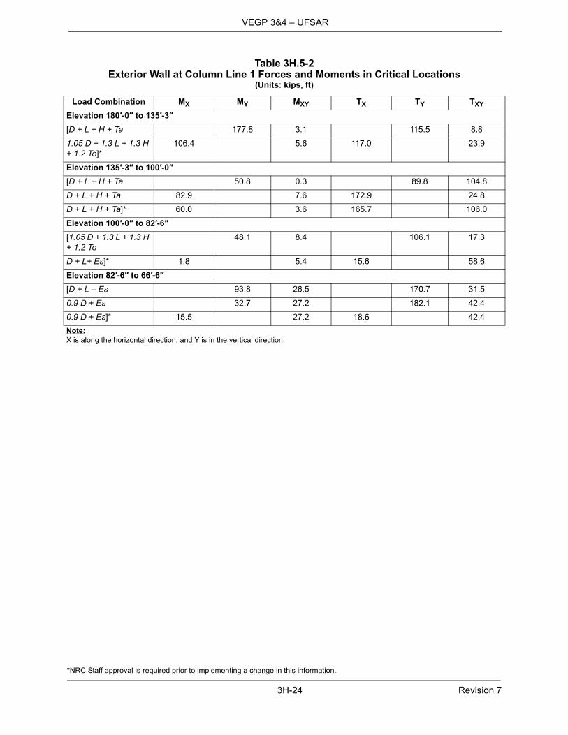
Table 3H.5-2Exterior Wall at Column Line 1 Forces and Moments in Critical Locations
(Units: kips, ft)
Load Combination MX MY MXY TX TY TXY
Elevation 180′-0″ to 135′-3″[D + L + H + Ta 177.8 3.1 115.5 8.8
1.05 D + 1.3 L + 1.3 H + 1.2 To]*
106.4 5.6 117.0 23.9
Elevation 135′-3″ to 100′-0″[D + L + H + Ta 50.8 0.3 89.8 104.8
D + L + H + Ta 82.9 7.6 172.9 24.8
D + L + H + Ta]* 60.0 3.6 165.7 106.0
Elevation 100′-0″ to 82′-6″[1.05 D + 1.3 L + 1.3 H + 1.2 To
48.1 8.4 106.1 17.3
D + L+ Es]* 1.8 5.4 15.6 58.6
Elevation 82′-6″ to 66′-6″[D + L – Es 93.8 26.5 170.7 31.5
0.9 D + Es 32.7 27.2 182.1 42.4
0.9 D + Es]* 15.5 27.2 18.6 42.4
Note:X is along the horizontal direction, and Y is in the vertical direction.

*NRC Staff approval is required prior to implementing a change in this information.
3H-25 Revision 7
VEGP 3&4 – UFSAR
Table 3H.5-3Exterior Wall on Column Line 1 Details of Wall Reinforcement (in 2/ft)
(See Figure 3H.5-2 for Locations of Wall Sections.)
Wall Segment(See detail in
Subsection 3H.5.1.1.) Location
Required(2) [Provided (Minimum)]*
Vertical Horizontal Shear(3) Vertical Horizontal Shear(3)
Wall Section 1, 6
Elevation 180′-0″ to 135′-3″ NR None
Outside Face 3.48 2.65 [3.91 3.12
Inside Face 1.94 1.52 3.12 3.12]*
Wall Section 2, 3, 7
Elevation 135′-3″ to 100′-0″ NR None
Outside Face 1.88 3.04 [3.12 3.12
Inside Face 1.77 2.23 3.12 3.12]*
Wall Section 4, 8
Elevation 100′-0″ to 82′-6″ 0.003 [0.44]*
Outside Face 1.42 0.70 [3.12 1.56
Inside Face 1.01 0.70 3.12 1.27]*
Wall Section 5, 9
Elevation 82′-6″ to 66′-6″ 0.27 [0.88]*
Outside Face 2.29 0.87 [4.39 1.27
Inside Face 1.87 0.87 3.12 1.27]*
Notes:1. NR = not required.2. Thermal loads have been considered in the design of critical sections. The required reinforcement values shown do not include
the load case where seismic and normal thermal loads are numerically combined as the normal thermal loads were assessed to be insignificant. When the seismic and normal thermal loads are numerically combined, the value of required reinforcementmay increase; however, in all cases the required reinforcement is less than the provided reinforcement and thus the design ofthe critical section reinforcement is acceptable.
3. Refer to Subsection 3.8.4.4.1 for the requirements for shear reinforcement.

*NRC Staff approval is required prior to implementing a change in this information.
3H-26 Revision 7
VEGP 3&4 – UFSAR
Note:X is along the horizontal direction, and Y is in the vertical direction.
Table 3H.5-4Interior Wall at Column Line 7.3 Forces and Moments in Critical Locations
(Units: kips, ft)
Load Combination MX MY MXY TX TY TXY
From Roof to Elevation 155′-6″[1.05 D + 1.3 L + 1.2 To 135.3 10.9 117.3 210.2
1.05 D + 1.3 L + 1.2 To]* 75.5 4.1 229.8 94.3
Elevation 155′-6″ to 135′-3″[0.9 D – Es 14.1 1.3 160.8 228.7
D + L – Es]* 28.0 1.0 29.8 231.7
Elevation 135′-3″ to 117′-6″[0.9 D – Es 3.3 1.3 142.2 140.9
D + L – Es]* 10.0 1.0 41.7 175.0
Elevation 117′-6″ to 100′-0″[0.9 D – Es 4.7 2.8 143.9 184.9
D + L + Es]* 6.4 1.5 172.8 107.9
Elevation 100′-0″ to 82′-6″[0.9 D – Es 15.4 2.6 90.4 169.8
D + L – Es]* 8.7 2.6 46.6 175.6
Elevation 82′-6″ to 66′-6″[0.9 D – Es 23.5 1.3 80.9 49.3
D + L – Es]* 0.8 1.3 1.7 74.1

*NRC Staff approval is required prior to implementing a change in this information.
3H-27 Revision 7
VEGP 3&4 – UFSAR
Notes:1. Thermal loads have been considered in the design of critical sections. The required reinforcement values shown do not include
the load case where seismic and normal thermal loads are numerically combined as the normal thermal loads were assessed to be insignificant. When the seismic and normal thermal loads are numerically combined, the value of required reinforcement may increase; however, in all cases the required reinforcement is less than the provided reinforcement and thus the design of the critical section reinforcement is acceptable.
2. Refer to Subsection 3.8.4.4.1 for the requirements for shear reinforcement.3. For Vogtle Unit 3, a single reinforcement bar is developed above elevation 82'-6" near the shield building with a headed reinforcement
bar effectively reducing the minimum provided area of steel in this wall to 3.08in2/ft. The provided minimum reinforcement is reducedalong the development length of the single bar, though it does not change the performance of the existing structure under postulatedloads and does not cause any excessive stress locally along the development length of the bar. The number of bars in the wall forboth units is unchanged per Figure 3H.5-4.]*
Table 3H.5-5Interior Wall on Column Line 7.3 Details of Wall Reinforcement
(See Figure 3H.5-2 for Locations of Wall Sections.)
Wall Segment(See detail in
Subsection 3H.5.1.2.) Location Wall Section
Reinforcement on Each Face (in2/ft)
Required(1) [Provided (Min.)]*
From Roof to Elevation 155′-6″ Horizontal 1 3.96 [4.12
Vertical 7 3.60 3.72
Elevation 155′-6″ to 135′-3″ Horizontal 2 2.80 3.12
Vertical 8 3.59 3.72
Elevation 135′-3″ to 117′-6″ Horizontal 3 2.03 2.54
Vertical 9 2.63 3.12
Elevation 117′-6″ to 100′-0″ Horizontal 4 2.29 2.54
Vertical 10 2.98 3.12
Elevation 100′-0″ to 82′-6″ Horizontal 5 1.69 2.54
Vertical 11 2.08 3.12(3)
Elevation 82′-6″ to 66′-6″ Horizontal 6 0.85 1.27
Vertical 12 0.98 1.56
Shear Reinforcement(2) (in2/ft2)
From Roof to Elevation 155′-6″ Standard hook or T headed bar
7 0.38 0.44]*
[

*NRC Staff approval is required prior to implementing a change in this information.
3H-28 Revision 7
VEGP 3&4 – UFSAR
Table 3H.5-6Interior Wall at Column Line L Forces and Moments in Critical Locations
(Units: kips, ft)
Load Combination MX MY MXY TX TY TXY
Elevation 154′-2″ to 135′-3″[0.9 D + Es+ Pa + Yj 6.0 3.5 115.4 170.2
0.9 D + Es+ Pa + Yj]* 14.3 3.5 46.0 170.2
Elevation 135′-3″ to 117′-6″[0.9 D + Es+ Pa + Yj 145.3 12.2 26.0 38.2
0.9 D + Es+ Pa + Yj]* 24.5 7.1 15.5 114.9
Note:X is along the horizontal direction, and Y is in the vertical direction.

*NRC Staff approval is required prior to implementing a change in this information.
3H-29 Revision 7
VEGP 3&4 – UFSAR
Notes:1. Thermal loads have been considered in the design of critical sections. The required reinforcement values shown do not include
the load case where seismic and normal thermal loads are numerically combined as the normal thermal loads were assessed to be insignificant. When the seismic and normal thermal loads are numerically combined, the value of required reinforcement may increase; however, in all cases the required reinforcement is less than the provided reinforcement and thus the design of the critical section reinforcement is acceptable.
2. Refer to Subsection 3.8.4.4.1 for the requirements for shear reinforcement.
Table 3H.5-7Interior Wall on Column Line L Details of Wall Reinforcement
(See Figure 3H.5-2, Sheet 3, for Locations of Wall Sections.)
Wall Segment(See detail in
Subsection 3H.5.1.3.) LocationWall
Section
Reinforcement on Each Face (in2/ft2)
Required(1) [Provided (Min.)]*
Elevation 154′-2″ to 135′-3″ Horizontal 1 2.08 [2.27
Vertical 3 2.59 3.12
Elevation 135′-3″ to 117′-6″ Horizontal 2 1.36 4.39
Vertical 4 2.02 5.66]*
Shear Reinforcement(2) (in2/ft2)
Elevation 154′-2″ to 135′-3″ Standard hook or T headed bar
5 0.01 [0.11
Elevation 135′-3″ to 117′-6″ Standard hook or T headed bar
6 0.33 1.76]*

*NRC Staff approval is required prior to implementing a change in this information.
3H-30 Revision 7
VEGP 3&4 – UFSAR
Notes:x – direction is horizontal; y – direction is vertical.See Figure 3H.5-10 for element location.Plate thickness required for load combinations excluding thermal: 0.42 inches (Maximum)[Plate thickness provided: 0.50 -0.01 +0.10 inches]*Maximum principal stress for load combination 5 including thermal: 46.33 ksi[Yield stress: 65.0 ksi (Minimum)]*Maximum stress intensity range for load combination 5 including thermal: 46.3 ksiAllowable stress intensity: 130.0 ksi (Minimum)
Table 3H.5-8 (Sheet 1 of 7)Design Summary of Spent Fuel Pool Wall Design Loads, Load Combinations, and
Comparisons to Acceptance Criteria – Element No. 20477
Load/Combination
Sxx kip/ft
Syykip/ft
Sxykip/ft
Mxxk-ft/ft
Myyk-ft/ft
Nxkip/ft
Nykip/ft Comments
Dead (D) -16.15 -22.92 -28.34 -1.34 -1.06 -0.32 -0.32
Live (L) 1.46 0.32 -1.57 -0.06 -0.21 0.04 0.03
Hydro (F) 37.52 12.36 -4.32 -100.50 -14.49 62.14 -9.95
Seismic (Es) 46.21 56.51 183.20 81.72 28.70 103.00 14.79
Thermal (To) -561.80 -267.70 -51.15 -426.90 -145.50 90.32 -23.66
Thermal (Ta) -955.80 -444.60 -139.70 -1401.0 -450.00 227.50 -83.16
LC(1a) 32.40 -14.25 -48.39 -142.68 -22.12 86.61 -14.33 [1.4D+1.7L+1.4F
LC(3a) 84.05 51.21 147.24 -60.38 7.15 189.71 0.56 D+L+F+Es
LC(3b) 84.05 51.21 -219.16 -223.82 -50.25 -16.29 -29.02 D+L+F+E's
LC(3e) -267.08 -116.11 115.28 -327.19 -83.79 246.16 -14.22 D+L+F+Es+To
LC(3f) -267.08 -116.11 -251.12 -490.63 -141.19 40.16 -43.80 D+L+F+E's+To
LC(3m) 84.20 53.18 151.64 -60.18 7.46 189.71 0.57 0.9D+F+Es
LC(3n) 84.20 53.18 -214.76 -223.62 -49.94 -16.29 -29.01 0.9D+F+E's
LC(3o) -266.92 -114.13 119.68 -326.99 -83.47 246.16 -14.22 0.9D+F+Es+To
LC(3p) -266.92 -114.13 -246.72 -490.43 -140.87 40.16 -43.80 0.9D+F+E's+To
LC(5a) -574.55 -288.12 -121.54 -977.52 -297.00 204.04 -62.22 D+L+F+Ta
LC(5b) -825.30 -421.18 -153.29 -53.19 -5.28 63.89 -15.73 D+L+F+Ta
LC(7a) -397.01 -211.45 -74.69 -427.19 -125.72 132.70 -28.49 1.05D+1.3L+1.05F+1.2To]*
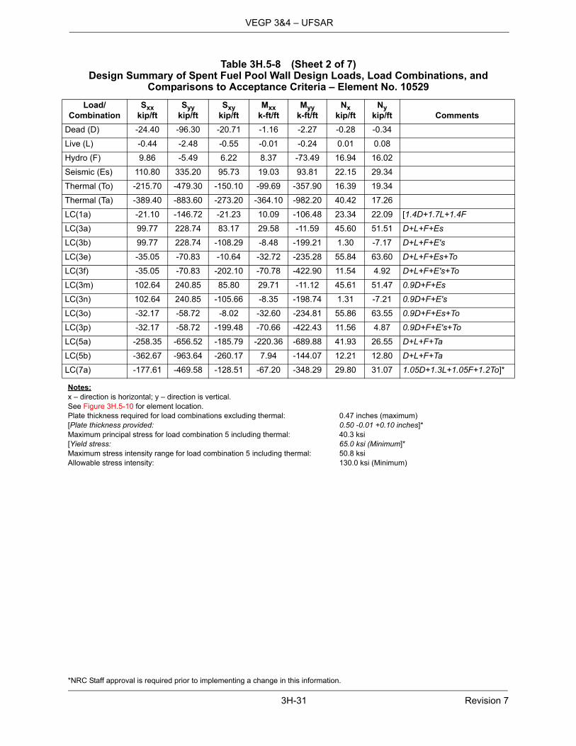
*NRC Staff approval is required prior to implementing a change in this information.
3H-31 Revision 7
VEGP 3&4 – UFSAR
Notes:x – direction is horizontal; y – direction is vertical.See Figure 3H.5-10 for element location.Plate thickness required for load combinations excluding thermal: 0.47 inches (maximum)[Plate thickness provided: 0.50 -0.01 +0.10 inches]*Maximum principal stress for load combination 5 including thermal: 40.3 ksi[Yield stress: 65.0 ksi (Minimum]*Maximum stress intensity range for load combination 5 including thermal: 50.8 ksiAllowable stress intensity: 130.0 ksi (Minimum)
Table 3H.5-8 (Sheet 2 of 7)Design Summary of Spent Fuel Pool Wall Design Loads, Load Combinations, and
Comparisons to Acceptance Criteria – Element No. 10529
Load/Combination
Sxx kip/ft
Syykip/ft
Sxykip/ft
Mxxk-ft/ft
Myyk-ft/ft
Nxkip/ft
Nykip/ft Comments
Dead (D) -24.40 -96.30 -20.71 -1.16 -2.27 -0.28 -0.34
Live (L) -0.44 -2.48 -0.55 -0.01 -0.24 0.01 0.08
Hydro (F) 9.86 -5.49 6.22 8.37 -73.49 16.94 16.02
Seismic (Es) 110.80 335.20 95.73 19.03 93.81 22.15 29.34
Thermal (To) -215.70 -479.30 -150.10 -99.69 -357.90 16.39 19.34
Thermal (Ta) -389.40 -883.60 -273.20 -364.10 -982.20 40.42 17.26
LC(1a) -21.10 -146.72 -21.23 10.09 -106.48 23.34 22.09 [1.4D+1.7L+1.4F
LC(3a) 99.77 228.74 83.17 29.58 -11.59 45.60 51.51 D+L+F+Es
LC(3b) 99.77 228.74 -108.29 -8.48 -199.21 1.30 -7.17 D+L+F+E's
LC(3e) -35.05 -70.83 -10.64 -32.72 -235.28 55.84 63.60 D+L+F+Es+To
LC(3f) -35.05 -70.83 -202.10 -70.78 -422.90 11.54 4.92 D+L+F+E's+To
LC(3m) 102.64 240.85 85.80 29.71 -11.12 45.61 51.47 0.9D+F+Es
LC(3n) 102.64 240.85 -105.66 -8.35 -198.74 1.31 -7.21 0.9D+F+E's
LC(3o) -32.17 -58.72 -8.02 -32.60 -234.81 55.86 63.55 0.9D+F+Es+To
LC(3p) -32.17 -58.72 -199.48 -70.66 -422.43 11.56 4.87 0.9D+F+E's+To
LC(5a) -258.35 -656.52 -185.79 -220.36 -689.88 41.93 26.55 D+L+F+Ta
LC(5b) -362.67 -963.64 -260.17 7.94 -144.07 12.21 12.80 D+L+F+Ta
LC(7a) -177.61 -469.58 -128.51 -67.20 -348.29 29.80 31.07 1.05D+1.3L+1.05F+1.2To]*
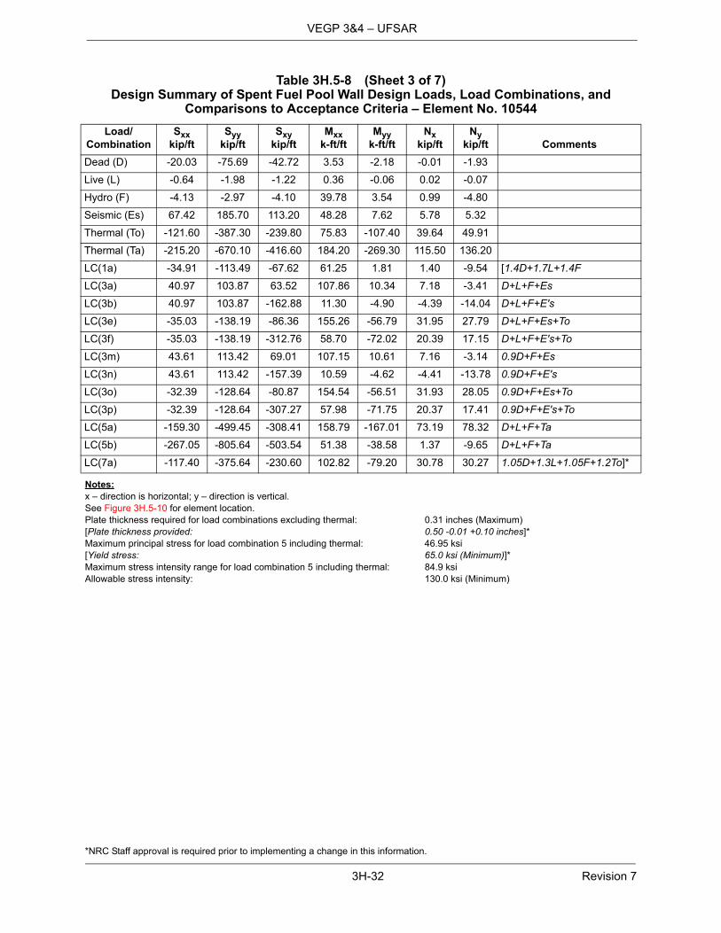
*NRC Staff approval is required prior to implementing a change in this information.
3H-32 Revision 7
VEGP 3&4 – UFSAR
Notes:x – direction is horizontal; y – direction is vertical.See Figure 3H.5-10 for element location.Plate thickness required for load combinations excluding thermal: 0.31 inches (Maximum)[Plate thickness provided: 0.50 -0.01 +0.10 inches]*Maximum principal stress for load combination 5 including thermal: 46.95 ksi[Yield stress: 65.0 ksi (Minimum)]*Maximum stress intensity range for load combination 5 including thermal: 84.9 ksiAllowable stress intensity: 130.0 ksi (Minimum)
Table 3H.5-8 (Sheet 3 of 7)Design Summary of Spent Fuel Pool Wall Design Loads, Load Combinations, and
Comparisons to Acceptance Criteria – Element No. 10544
Load/Combination
Sxx kip/ft
Syykip/ft
Sxykip/ft
Mxxk-ft/ft
Myyk-ft/ft
Nxkip/ft
Nykip/ft Comments
Dead (D) -20.03 -75.69 -42.72 3.53 -2.18 -0.01 -1.93
Live (L) -0.64 -1.98 -1.22 0.36 -0.06 0.02 -0.07
Hydro (F) -4.13 -2.97 -4.10 39.78 3.54 0.99 -4.80
Seismic (Es) 67.42 185.70 113.20 48.28 7.62 5.78 5.32
Thermal (To) -121.60 -387.30 -239.80 75.83 -107.40 39.64 49.91
Thermal (Ta) -215.20 -670.10 -416.60 184.20 -269.30 115.50 136.20
LC(1a) -34.91 -113.49 -67.62 61.25 1.81 1.40 -9.54 [1.4D+1.7L+1.4F
LC(3a) 40.97 103.87 63.52 107.86 10.34 7.18 -3.41 D+L+F+Es
LC(3b) 40.97 103.87 -162.88 11.30 -4.90 -4.39 -14.04 D+L+F+E's
LC(3e) -35.03 -138.19 -86.36 155.26 -56.79 31.95 27.79 D+L+F+Es+To
LC(3f) -35.03 -138.19 -312.76 58.70 -72.02 20.39 17.15 D+L+F+E's+To
LC(3m) 43.61 113.42 69.01 107.15 10.61 7.16 -3.14 0.9D+F+Es
LC(3n) 43.61 113.42 -157.39 10.59 -4.62 -4.41 -13.78 0.9D+F+E's
LC(3o) -32.39 -128.64 -80.87 154.54 -56.51 31.93 28.05 0.9D+F+Es+To
LC(3p) -32.39 -128.64 -307.27 57.98 -71.75 20.37 17.41 0.9D+F+E's+To
LC(5a) -159.30 -499.45 -308.41 158.79 -167.01 73.19 78.32 D+L+F+Ta
LC(5b) -267.05 -805.64 -503.54 51.38 -38.58 1.37 -9.65 D+L+F+Ta
LC(7a) -117.40 -375.64 -230.60 102.82 -79.20 30.78 30.27 1.05D+1.3L+1.05F+1.2To]*

*NRC Staff approval is required prior to implementing a change in this information.
3H-33 Revision 7
VEGP 3&4 – UFSAR
Notes:x – direction is horizontal; y – direction is vertical.See Figure 3H.5-10 for element location.Plate thickness required for load combinations excluding thermal: 0.32 inches (Maximum)[Plate thickness provided: 0.50 -0.01 +0.10 inches]*Maximum principal stress for load combination 5 including thermal: 42.1 ksi[Yield stress: 65.0 ksi (Minimum)]*Maximum stress intensity range for load combination 5 including thermal: 72.5 ksiAllowable stress intensity: 130.0 ksi (Minimum)
Table 3H.5-8 (Sheet 4 of 7)Design Summary of Spent Fuel Pool Wall Design Loads, Load Combinations, and
Comparisons to Acceptance Criteria – Element No. 10524
Load/Combination
Sxx kip/ft
Syykip/ft
Sxykip/ft
Mxxk-ft/ft
Myyk-ft/ft
Nxkip/ft
Nykip/ft Comments
Dead (D) -35.61 -104.80 0.68 -4.70 7.72 -0.55 -2.22
Live (L) -0.45 -2.21 -0.72 -0.25 -0.49 0.00 0.10
Hydro (F) 11.85 -1.35 4.92 28.52 16.50 3.71 3.79
Seismic (Es) 76.80 225.60 79.29 53.31 177.00 6.83 55.70
Thermal (To) -369.10 -433.40 179.90 -215.40 -109.40 -7.32 -59.63
Thermal (Ta) -696.60 -730.00 329.40 -555.10 -487.60 -13.58 -95.78
LC(1a) -34.04 -152.37 6.62 32.92 33.09 4.43 2.37 [1.4D+1.7L+1.4F
LC(3a) 57.33 116.69 86.14 88.29 207.34 11.48 58.89 D+L+F+Es
LC(3b) 57.33 116.69 -72.44 -18.33 -146.66 -2.18 -52.51 D+L+F+E's
LC(3e) -173.36 -154.18 198.57 -46.34 138.96 6.90 21.62 D+L+F+Es+To
LC(3f) -173.36 -154.18 39.99 -152.96 -215.04 -6.76 -89.78 D+L+F+E's+To
LC(3m) 61.34 129.38 86.78 89.00 207.05 11.53 59.02 0.9D+F+Es
LC(3n) 61.34 129.38 -71.80 -17.62 -146.95 -2.13 -52.38 0.9D+F+E's
LC(3o) -169.35 -141.49 199.22 -45.62 138.68 6.96 21.75 0.9D+F+Es+To
LC(3p) -169.35 -141.49 40.64 -152.24 -215.32 -6.71 -89.65 0.9D+F+E's+To
LC(5a) -459.59 -564.62 210.75 -323.37 -281.01 -5.32 -58.19 D+L+F+Ta
LC(5b) -741.71 -755.24 398.88 19.86 124.99 -105.77 -114.64 D+L+F+Ta
LC(7a) -302.36 -439.4 139.9 136.9 57.2 -2.2 -42.9 1.05D+1.3L+1.05F+1.2To]*

*NRC Staff approval is required prior to implementing a change in this information.
3H-34 Revision 7
VEGP 3&4 – UFSAR
Notes:x – direction is horizontal; y – direction is vertical.See Figure 3H.5-10 for element location.Plate thickness required for load combinations excluding thermal: 0.20 inches (Maximum)[Plate thickness provided: 0.50 -0.01 +0.10 inches]*Maximum principal stress for load combination 5 including thermal: 20.6 ksi[Yield stress: 65.0 ksi (Minimum)]*Maximum stress intensity range for load combination 5 including thermal: 20.6 ksiAllowable stress intensity: 130.0 ksi (Minimum)
Table 3H.5-8 (Sheet 5 of 7)Design Summary of Spent Fuel Pool Wall Design Loads, Load Combinations, and
Comparisons to Acceptance Criteria – Element No. 20462
Load/Combination
Sxx kip/ft
Syykip/ft
Sxykip/ft
Mxxk-ft/ft
Myyk-ft/ft
Nxkip/ft
Nykip/ft Comments
Dead (D) -7.31 -29.13 -1.51 -1.45 -3.75 -0.06 0.35
Live (L) -0.11 -0.55 0.21 -0.14 -0.60 0.00 0.05
Hydro (F) 5.04 -0.04 -1.61 -16.58 64.59 -1.48 -20.87
Seismic (Es) 25.64 33.82 32.90 10.45 114.90 2.48 12.55
Thermal (To) -286.10 -78.70 66.37 -208.70 -130.00 0.86 -1.51
Thermal (Ta) -616.80 -121.80 116.60 -650.20 -502.40 6.16 3.93
LC(1a) -3.36 -41.77 -4.01 -25.47 84.16 -2.15 -28.64 [1.4D+1.7L+1.4F
LC(3a) 25.28 4.09 29.35 -14.35 200.98 0.35 -16.27 D+L+F+Es
LC(3b) 25.28 4.09 -36.45 -35.25 -28.82 -4.61 -41.37 D+L+F+E's
LC(3e) -153.54 -45.10 70.83 -144.78 119.73 0.89 -17.21 D+L+F+Es+To
LC(3f) -153.54 -45.10 5.03 -165.68 -110.07 -4.07 -42.31 D+L+F+E's+To
LC(3m) 26.11 7.55 29.29 -14.06 201.95 0.35 -16.35 0.9D+F+Es
LC(3n) 26.11 7.55 -36.51 -34.96 -27.85 -4.61 -41.45 0.9D+F+E's
LC(3o) -152.70 -41.63 70.77 -144.50 120.70 0.89 -17.29 0.9D+F+Es+To
LC(3p) -152.70 -41.63 4.97 -165.40 -109.10 -4.07 -42.39 0.9D+F+E's+To
LC(5a) -387.88 -105.84 69.97 -424.54 -253.76 2.31 -18.01 D+L+F+Ta
LC(5b) -646.13 -113.41 80.41 35.38 175.18 -4.36 -31.38 D+L+F+Ta
LC(7a) -217.10 -90.37 46.78 -175.63 -34.40 -0.96 -22.61 1.05D+1.3L+1.05F+1.2To]*
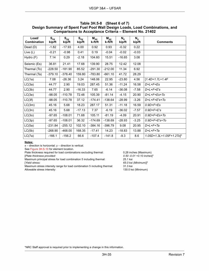
*NRC Staff approval is required prior to implementing a change in this information.
3H-35 Revision 7
VEGP 3&4 – UFSAR
Notes:x – direction is horizontal; y – direction is vertical.See Figure 3H.5-10 for element location.Plate thickness required for load combinations excluding thermal: 0.28 inches (Maximum)[Plate thickness provided: 0.50 -0.01 +0.10 inches]*Maximum principal stress for load combination 5 including thermal: 25.1 ksi[Yield stress: 65.0 ksi (Minimum)]*Maximum stress intensity range for load combination 5 including thermal: 31.3 ksiAllowable stress intensity: 130.0 ksi (Minimum)
Table 3H.5-8 (Sheet 6 of 7)Design Summary of Spent Fuel Pool Wall Design Loads, Load Combinations, and
Comparisons to Acceptance Criteria – Element No. 21402
Load/Combination
Sxx kip/ft
Syykip/ft
Sxykip/ft
Mxxk-ft/ft
Myyk-ft/ft
Nxkip/ft
Nykip/ft Comments
Dead (D) -1.82 -17.93 4.00 0.92 0.93 -0.32 0.22
Live (L) -0.21 -0.98 0.41 0.19 -0.04 -0.02 -0.03
Hydro (F) 7.14 0.29 -2.18 104.60 15.51 -16.65 3.08
Seismic (Es) 36.81 21.41 17.68 139.90 28.75 12.42 12.08
Thermal (To) -228.50 -181.90 85.52 -291.30 -212.00 11.34 6.92
Thermal (Ta) -379.10 -378.40 159.80 -783.80 -661.10 41.72 28.29
LC(1a) 7.08 -26.36 3.24 148.06 22.95 -23.80 4.56 [1.4D+1.7L+1.4F
LC(3a) 44.77 2.90 19.03 287.45 51.36 -11.24 16.58 D+L+F+Es
LC(3b) 44.77 2.90 -16.33 7.65 -6.14 -36.08 -7.58 D+L+F+E's
LC(3e) -98.05 -110.78 72.48 105.39 -81.14 -4.15 20.90 D+L+F+Es+To
LC(3f) -98.05 -110.78 37.12 -174.41 -138.64 -28.99 -3.26 D+L+F+E's+To
LC(3m) 45.16 5.68 18.23 287.17 51.31 -11.18 16.59 0.9D+F+Es
LC(3n) 45.16 5.68 -17.13 7.37 -6.19 -36.02 -7.57 0.9D+F+E's
LC(3o) -97.65 -108.01 71.68 105.11 -81.19 -4.09 20.91 0.9D+F+Es+To
LC(3p) -97.65 -108.01 36.32 -174.69 -138.69 -28.93 -3.25 0.9D+F+E's+To
LC(5a) -231.84 -255.12 102.10 -384.16 -396.79 9.08 20.95 D+L+F+Ta
LC(5b) -268.90 -468.00 168.35 -17.41 14.23 -18.83 13.88 D+L+F+Ta
LC(7a) -166.1 -156.2 66.6 -107.4 -141.8 -9.3 8.6 1.05D+1.3L+1.05F+1.2To]*

*NRC Staff approval is required prior to implementing a change in this information.
3H-36 Revision 7
VEGP 3&4 – UFSAR
Notes:x – direction is horizontal; y – direction is vertical.See Figure 3H.5-10 for element location.Plate thickness required for load combinations excluding thermal: 0.14 inches (Maximum)[Plate thickness provided: 0.50 -0.01 +0.10 inches]*Maximum principal stress for load combination 5 including thermal: 22.1 ksi[Yield stress: 65.0 ksi (Minimum)]*Maximum stress intensity range for load combination 5 including thermal: 22.1 ksiAllowable stress intensity: 130.0 ksi (Minimum)
Table 3H.5-8 (Sheet 7 of 7)Design Summary of Spent Fuel Pool Wall Design Loads, Load Combinations, and
Comparisons to Acceptance Criteria – Element No. 21414
Load/Combination
Sxx kip/ft
Syykip/ft
Sxykip/ft
Mxxk-ft/ft
Myyk-ft/ft
Nxkip/ft
Nykip/ft Comments
Dead (D) 0.69 -10.62 -2.57 -0.52 -0.22 -0.03 0.12
Live (L) 0.18 0.12 -0.45 0.00 -0.11 -0.01 0.02
Hydro (F) 4.25 0.56 -2.73 -27.01 -31.06 -1.46 1.82
Seismic (Es) 26.90 13.88 36.68 26.35 21.70 2.17 4.34
Thermal (To) -79.35 -40.69 49.04 -129.00 -119.30 10.01 6.90
Thermal (Ta) -129.60 -66.37 57.50 -374.60 -374.70 26.38 24.34
LC(1a) 7.24 -13.89 -8.19 -38.54 -43.97 -2.09 2.75 [1.4D+1.7L+1.4F
LC(3a) 33.73 4.16 29.84 -11.98 -22.11 0.10 7.03 D+L+F+Es
LC(3b) 33.73 4.16 -43.52 -64.68 -65.51 -4.24 -1.66 D+L+F+E's
LC(3e) -15.86 -21.27 60.49 -92.61 -96.67 6.36 11.34 D+L+F+Es+To
LC(3f) -15.86 -21.27 -12.87 -145.31 -140.07 2.01 2.66 D+L+F+E's+To
LC(3m) 33.48 5.10 30.55 -11.93 -21.98 0.11 7.00 0.9D+F+Es
LC(3n) 33.48 5.10 -42.81 -64.63 -65.38 -4.23 -1.69 0.9D+F+E's
LC(3o) -16.12 -20.33 61.20 -92.56 -96.54 6.37 11.31 0.9D+F+Es+To
LC(3p) -16.12 -20.33 -12.16 -145.26 -139.94 2.02 2.62 0.9D+F+E's+To
LC(5a) -75.87 -51.43 30.19 -261.65 -265.57 15.00 17.17 D+L+F+Ta
LC(5b) -114.31 -96.07 55.47 -35.06 -36.08 2.55 -1.61 D+L+F+Ta
LC(7a) -54.08 -40.93 30.63 -125.65 -122.46 5.94 7.24 1.05D+1.3L+1.05F+1.2To]*

*NRC Staff approval is required prior to implementing a change in this information.
3H-37 Revision 7
VEGP 3&4 – UFSAR
Notes:1. [Two percent of the value may be added to the design limit as an allowance for minor variances in analysis results.]*2. Thermal loads have been considered in the design of critical sections. The required reinforcement values shown do not include
the load case where seismic and normal thermal loads are numerically combined as the normal thermal loads were assessed tobe insignificant. When the seismic and normal thermal loads are numerically combined, the value of required reinforcementmay increase; however, in all cases the required reinforcement is less than the provided reinforcement and thus the design ofthe critical section reinforcement is acceptable.
Table 3H.5-9 (Sheet 1 of 3)Shield Building Roof Reinforcement Summary
(Tension Ring)
Tension Ring – Axial Force and Bending Verification
Location
Seismic Maximum Stresses Maximum
Stressesksi
Fyksi
Maximum Steel Area Required(2)
(in2/ft)[Steel Area Provided]*
[Design Limit(1) for Ratio
Max Required/ Provided]*Section Angles
Seismic L/C
faksi
2 lower5.625° 9 14.31
15.35 50 9.21[Liner 1 1/2" =
18 (in2/ft) (Min)]*[0.51 + 2%]*
84.375° 17 13.15
1 lower0° 9 15.35
90° 17 14.46
Tension Ring – Shear Force and Torsion Verification
Location
Seismic Maximum Stresses Maximum
Stressesksi
Fyksi
Maximum Steel Area Required(2)
(in2/ft)[Steel Area Provided]*
[Design Limit for Ratio
Max Required/ Provided]*Section Angles
Seismic L/C
fvksi
2 lower5.625° 18 4.83
6.28 50 5.65[Liner 1 1/2" =
18 (in2/ft) (Min.)]*[0.31 + 2%]*
84.375° 11 5.52
1 lower0° 17 6.28
90° 9 5.80
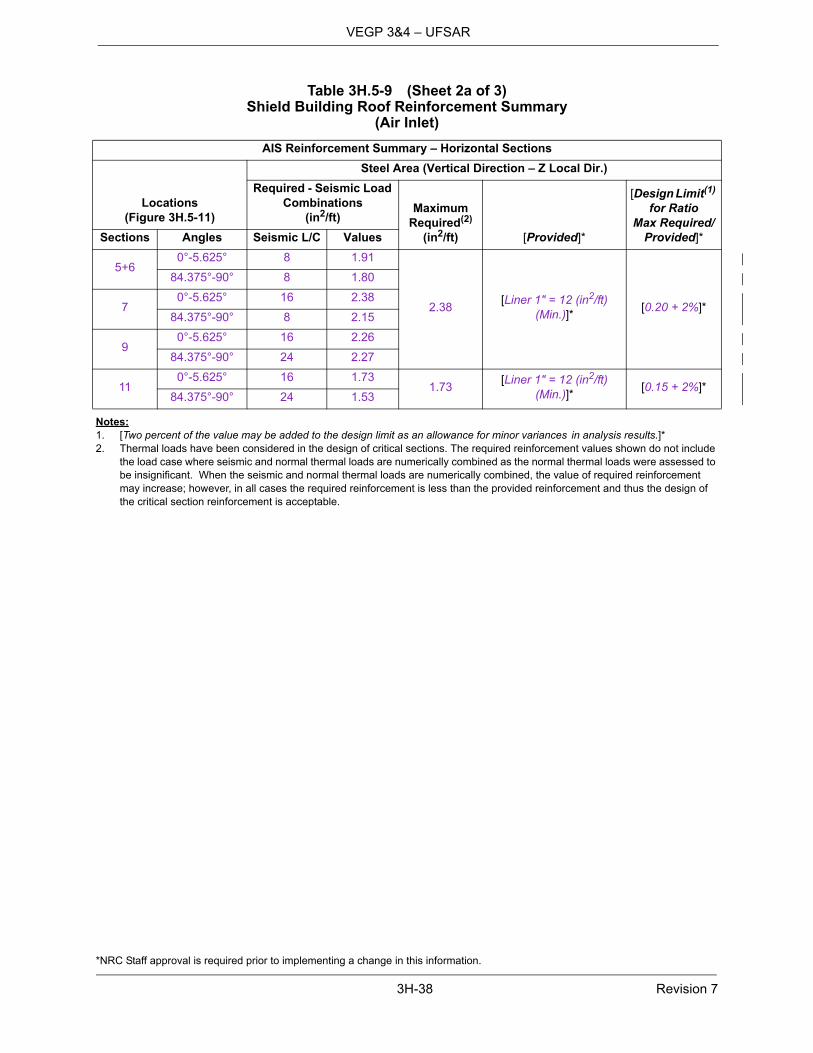
*NRC Staff approval is required prior to implementing a change in this information.
3H-38 Revision 7
VEGP 3&4 – UFSAR
Notes:1. [Two percent of the value may be added to the design limit as an allowance for minor variances in analysis results.]*2. Thermal loads have been considered in the design of critical sections. The required reinforcement values shown do not include
the load case where seismic and normal thermal loads are numerically combined as the normal thermal loads were assessed tobe insignificant. When the seismic and normal thermal loads are numerically combined, the value of required reinforcementmay increase; however, in all cases the required reinforcement is less than the provided reinforcement and thus the design ofthe critical section reinforcement is acceptable.
Table 3H.5-9 (Sheet 2a of 3)Shield Building Roof Reinforcement Summary
(Air Inlet)
AIS Reinforcement Summary – Horizontal Sections
Locations(Figure 3H.5-11)
Steel Area (Vertical Direction – Z Local Dir.)
Required - Seismic Load Combinations
(in2/ft)Maximum
Required(2)
(in2/ft) [Provided]*
[Design Limit(1) for Ratio
Max Required/Provided]*Sections Angles Seismic L/C Values
5+60°-5.625° 8 1.91
2.38[Liner 1" = 12 (in2/ft)
(Min.)]*[0.20 + 2%]*
84.375°-90° 8 1.80
70°-5.625° 16 2.38
84.375°-90° 8 2.15
90°-5.625° 16 2.26
84.375°-90° 24 2.27
110°-5.625° 16 1.73
1.73[Liner 1" = 12 (in2/ft)
(Min.)]*[0.15 + 2%]*
84.375°-90° 24 1.53

*NRC Staff approval is required prior to implementing a change in this information.
3H-39 Revision 7
VEGP 3&4 – UFSAR
Notes:1. [Two percent of the value may be added to the design limit as an allowance for minor variances in analysis results.]*2. Thermal loads have been considered in the design of critical sections. The required reinforcement values shown do not include
the load case where seismic and normal thermal loads are numerically combined as the normal thermal loads were assessed tobe insignificant. When the seismic and normal thermal loads are numerically combined, the value of required reinforcementmay increase; however, in all cases the required reinforcement is less than the provided reinforcement and thus the design ofthe critical section reinforcement is acceptable.
Table 3H.5-9 (Sheet 2b of 3)Shield Building Roof Reinforcement Summary
(Air Inlet)
AIS Reinforcement Summary – Vertical Sections
Locations(Figure 3H.5-11) Steel Area (Hoop Direction – Y Local Dir.)
Sections Angles
Required - Seismic Load Combinations
(in2/ft)Maximum
Required(2)
(in2/ft) [Provided]*
[Design Limit(1) for Ratio
Max Required/Provided]*Seismic L/C Values
3 Upper0° 9 9.97
10.53[Liner 1" = 12 (in2/ft)
(Min.)]*[0.88 + 2%]*
90° 17 9.25
3 Lower0° 9 8.45
90° 17 7.75
4 Upper5.625° 9 10.53
84.375° 17 9.75
4 Lower5.625° 10 8.26
84.375° 19 7.54

*NRC Staff approval is required prior to implementing a change in this information.
3H-40 Revision 7
VEGP 3&4 – UFSAR
Notes:1. [Two percent of the value may be added to the design limit as an allowance for minor variances in analysis results.]*2. Thermal loads have been considered in the design of critical sections. The required reinforcement values shown do not include
the load case where seismic and normal thermal loads are numerically combined as the normal thermal loads were assessed tobe insignificant. When the seismic and normal thermal loads are numerically combined, the value of required reinforcementmay increase; however, in all cases the required reinforcement is less than the provided reinforcement and thus the design ofthe critical section reinforcement is acceptable.
Table 3H.5-9 Sheet 2c of 3)(Shield Building Roof Reinforcement Summary
(Air Inlet)
Out of Plane Shear Reinforcement Summary – AIS
Locations(Figure 3H.5-11)
Required – Seismic Load Combinations
(in2/ft) Maximum Required(2)
(in2/ft)[Steel Area Provided]*
[Design Limit(1) for Ratio
Max Required/Provided]*Angles Sections
Seismic L/C Values Sum
0° - 5.625°
Max of Vertical Sections3 upper - 4 upper
1
0.13
0.13
0.34
[(3) 3/4'' TIE BAR @2.8125° (41.36")(8 1/2" in vertical
direction) = 0.50 (in2/ft) (Min.)]*
[0.68 + 2%]*
HorizontalSection 5+6
0.00
84.375° - 90°
Max of Vertical sections3 upper - 4 upper
1
0.12
0.12Horizontal
Section 5+60.00
0° - 5.625°
Max of Vertical Sections3 upper – 4 upper
1
0.10
0.34Horizontal Section 7
0.24
84.375° - 90°
Max of Vertical Sections3 upper – 4 upper
1
0.10
0.30HorizontalSection 7
0.20
0° - 5.625°
Max of Vertical Sections3 lower - 4 lower
18
0.21
0.21HorizontalSection 9
0.00
84.375° - 90°
Max of Vertical Sections3 lower - 4 lower
11
0.21
0.21Horizontal Section 9
0.000
0° - 5.625°
Max of Vertical Sections3 lower - 4 lower
18
0.21
0.21Horizontal Section 11
0.000
84.375° - 90°
Max of Vertical Sections3 lower - 4 lower
11
0.21
0.21HorizontalSection 11
0.00

*NRC Staff approval is required prior to implementing a change in this information.
3H-41 Revision 7
VEGP 3&4 – UFSAR
Table 3H.5-9 (Sheet 3 of 3)Shield Building Roof Reinforcement Summary
(Exterior Wall Of Passive Containment Cooling System Tank)
Wall Segment
Location(Figure 3H.5-11
Sheet 5 of 6)
Reinforcement on Each Face, in2/ft
RatioRequired/Provided
MaximumRequired Provided (Minimum)
Bottom
Vertical 1.49 1#[email protected]° & 1#[email protected]°
[2.75 0.54
Hoop 0.80 1#9@6" 2 0.40
Shear 0.15 1#[email protected]°x6" 0.94 0.16
Mid-height
Vertical 0.64 1#[email protected]° & 1#[email protected]°
2.75 0.23
Hoop 1.93 1#9@6" 2 0.97
Top
Vertical 0.52 1#[email protected]° & 1#[email protected]°
2.75 0.19
Hoop 0.79 1#9@6" 2]* 0.40

*NRC Staff approval is required prior to implementing a change in this information.
3H-42 Revision 7
VEGP 3&4 – UFSAR
Table 3H.5-10Design Summary Of Roof At Elevation 180′-0″, Area 6
(Near Shield Building Interface)
Governing Load Combination (Roof Girder)
Combination Number 7 – Abnormal Condition
Bending Moment = 8028 kip-ft
Corresponding Stress = 27.1 ksi
Allowable Stress = 53.0 ksi
Shear Force = 553 kips
Corresponding Stress = 11.5 ksi
Allowable Stress = 26.4 ksi
Governing Load Combination (Concrete Slab)
Parallel to Girders
Combination Numbers 7 – Abnormal Condition
Reinforcement (Each Face)
Required = 2.54 in2/ft
[Provided = 2.54 in2/ft (Minimum)]*
Perpendicular to Girders
Combination Numbers 3 – Extreme Environmental Condition
Reinforcement (Each Face)
Required = 2.37 in2/ft
[Provided = 3.12 in2/ft (Minimum)]*

*NRC Staff approval is required prior to implementing a change in this information.
3H-43 Revision 7
VEGP 3&4 – UFSAR
Note:1. Thermal loads have been considered in the design of critical sections. The required reinforcement values shown do not include
the load case where seismic and normal thermal loads are numerically combined as the normal thermal loads were assessed to be insignificant. When the seismic and normal thermal loads are numerically combined, the value of required reinforcement may increase; however, in all cases the required reinforcement is less than the provided reinforcement and thus the design of the critical section reinforcement is acceptable.
Table 3H.5-11Design Summary Of Floor At Elevation 135′-3″ Area 1 (Between Column Lines M And P)
Governing Load Combination (Steel Beam)
Load Combination 3 – Extreme Environmental Condition Downward Seismic
Bending Moment =(-) 63.9 kips-ft
Corresponding Stress = 17.0 ksi
Allowable Stress =33.26 ksi
Shear Force = 30.7 kips
Corresponding Stress = 8.7 ksi
Allowable Stress = 20.1 ksi
Governing Load Combination (Concrete Slab)
Parallel to the Beams
Load Combination 3 – Extreme Environmental Condition Downward Seismic
Bending Moment =(-) 16.0 kips-ft/ft
In-plane Shear =20.0 kips (per foot width of the slab)
Reinforcement (Each Face)
Required(1) = 0.41 in2/ft
[Provided = 0.44 in2/ft (Min.)]*
Perpendicular to the Beams
Combination Number Normal Condition
Bending Moment =(+) 6.66 kips-ft (per foot width of the slab)
Reinforcement (Each Face)
Required(1) = 0.28 in2/ft
[Provided = 0.60 in2/ft (Min.)]*

*NRC Staff approval is required prior to implementing a change in this information.
3H-44 Revision 7
VEGP 3&4 – UFSAR
Note:1. Thermal loads have been considered in the design of critical sections. The required reinforcement values shown do not include
the load case where seismic and normal thermal loads are numerically combined as the normal thermal loads were assessed to be insignificant. When the seismic and normal thermal loads are numerically combined, the value of required reinforcement may increase; however, in all cases the required reinforcement is less than the provided reinforcement and thus the design of the critical section reinforcement is acceptable.
Table 3H.5-12Design Summary Of Floor At Elevation 135′-3″
(Operations Work Area (Previously Known As ‘Tagging Room’) Ceiling))
Design of Precast Concrete Panels
Governing Load Combination Construction
Design Bending Moment (Midspan) = 14.53 kip-ft/ft
Bottom Reinforcement (E/W Direction)
Required(1) = 0.58 in2/ft
[Provided = 0.79 in2/ft (Min.)]*
Top Reinforcement (E/W Direction)
Required(1) = (Minimum required by Code)
[Provided = 0.20 in2/ft (Min.)]*
Top and Bottom Reinforcement (N/S Direction)
Required(1) = (Minimum required by Code)
[Provided = 0.20 in2/ft (Min.)]*
Design of 24-inch-Thick Slab
Governing Load Combination Extreme Environmental Condition (SSE)
Design Bending Moment (E/W Direction) Midspan = 14.40 kips ft/ft
Design In-plane Shear = 31.9 kips ft
Design In-plane Tension = 21.9 kips ft
Bottom Reinforcement (E/W Direction)
Required(1) = 0.53 in2/ft
[Provided = 0.79 in2/ft (Min.)]*
Design Bending Moment (E/W Direction) at Support = 28.81 kips-ft/ft
Design In-plane Shear = 31.9 kips/ft
Design In-plane Tension = 21.9 kips/ft
Top Reinforcement (E/W Direction)
Required(1) = 0.93 in2/ft
[Provided = 1.00 in2/ft (Min.)]*
Design Bending Moment (N/S Direction) = 8.47 kips ft/ft
Design In-plane Shear = 31.9 kips/ft
Design In-plane Tension = 27.2 kip/ ft
Top and Bottom Reinforcement (N/S Direction)
Required(1) = 0.59 in2/ft
[Provided = 0.79 in2/ft (Min.)]*
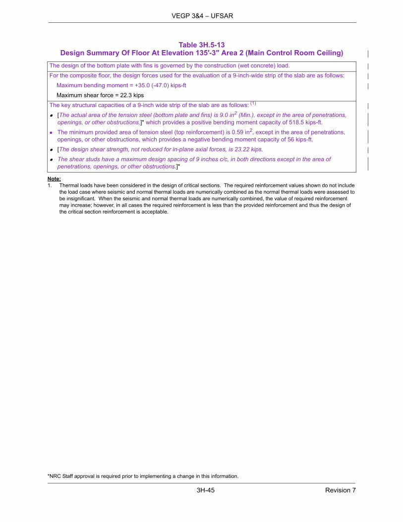
*NRC Staff approval is required prior to implementing a change in this information.
3H-45 Revision 7
VEGP 3&4 – UFSAR
Note:1. Thermal loads have been considered in the design of critical sections. The required reinforcement values shown do not include
the load case where seismic and normal thermal loads are numerically combined as the normal thermal loads were assessed to be insignificant. When the seismic and normal thermal loads are numerically combined, the value of required reinforcement may increase; however, in all cases the required reinforcement is less than the provided reinforcement and thus the design of the critical section reinforcement is acceptable.
Table 3H.5-13Design Summary Of Floor At Elevation 135′-3″ Area 2 (Main Control Room Ceiling)
The design of the bottom plate with fins is governed by the construction (wet concrete) load.
For the composite floor, the design forces used for the evaluation of a 9-inch-wide strip of the slab are as follows:
Maximum bending moment = +35.0 (-47.0) kips-ft
Maximum shear force = 22.3 kips
The key structural capacities of a 9-inch wide strip of the slab are as follows: (1)
[The actual area of the tension steel (bottom plate and fins) is 9.0 in2 (Min.), except in the area of penetrations,openings, or other obstructions,]* which provides a positive bending moment capacity of 518.5 kips-ft.
The minimum provided area of tension steel (top reinforcement) is 0.59 in2, except in the area of penetrations,openings, or other obstructions, which provides a negative bending moment capacity of 56 kips-ft.
[The design shear strength, not reduced for in-plane axial forces, is 23.22 kips.
The shear studs have a maximum design spacing of 9 inches c/c, in both directions except in the area ofpenetrations, openings, or other obstructions.]*

*NRC Staff approval is required prior to implementing a change in this information.
3H-46 Revision 7
VEGP 3&4 – UFSAR
Notes:1. [The Tier 2* designation for “Plate thickness required” requires NRC approval if this value is exceeded as a result of design
changes or detail design adjustments identified during preparation of fabrication or construction drawings or instructions.]*2. Load cases 35 and 37 are the two governing load combinations for element 12164 that include thermal and seismic loads
combined numerically. W1 designates the winter conditions with the spent fuel pool at the normal operating temperature limit. W2 designates the winter conditions with the spent fuel pool and fuel transfer canal at the normal operating temperature limit. Es is SRSS (member forces are positive) of the SSE loads. E's is Es with all member forces except axial forces (TX, TY) reversed to negative.
3. The 0.75-inch plate thickness is the nominal plate size for the shield building away from connections, attachments, and otherlocal loads. The plate may be thicker (up to 1.0-inch nominal thickness) in the area around these local loads.
Table 3H.5-14 (Sheet 1 of 3)Design Summary of Enhanced Shield Building Cylindrical Wall Load Combinations, and Comparison to Acceptance Criteria Elevation 180 Feet Near Fuel Handling Building Roof
Load/Combination
TX TY TXY MX MY MXY NX NY
Commentskip/ft kip/ft kip/ft k-ft/ft k-ft/ft k-ft/ft kip/ft kip/ft
Dead -7 -118 15 -25 -18 4 -6 -5
Live 1 -1 1 0 0 0 0 0
Seismic 157 390 163 301 211 35 71 33
1 -8 -168 22 -35 -24 5 -8 -7 1.4 D + 1.7 L
2 152 270 179 276 194 38 66 28 D + L + Es
3 152 270 -148 -326 -228 -31 -77 -38 D + L + E's
4 -163 -509 -148 -326 -228 -31 -77 -38 D + L - Es
5 -163 -509 179 276 194 38 66 28 D + L - E's
6 152 283 177 278 195 38 66 28 0.9 D + Es
7 152 283 -150 -324 -227 -31 -77 -38 0.9 D + E's
35(2) 205 399 233 449 303 69 105 31 0.9 D + E's + αTo(W1)
37(2) 221 387 238 460 311 68 108 31 0.9 D + E's + αTo(W2)
x-direction is horizontal; y-direction is vertical.Element number: 12164[Plate thickness required for load combinations excluding thermal: 0.50 inches + 2%(1)]*[Plate thickness required for load combinations including thermal: 0.65 inches + 2%(1)]*[Plate thickness provided: 0.75 inches]*(3)
[Shear reinforcement required for load combinations excluding thermal: 0.72 in2/ft2 + 2%(1)]*[Shear reinforcement required for load combinations including thermal: 1.00 in2/ft2 + 2%(1)]*Shear reinforcement provided: See [APP-GW-GLR-602, Section 4.]*
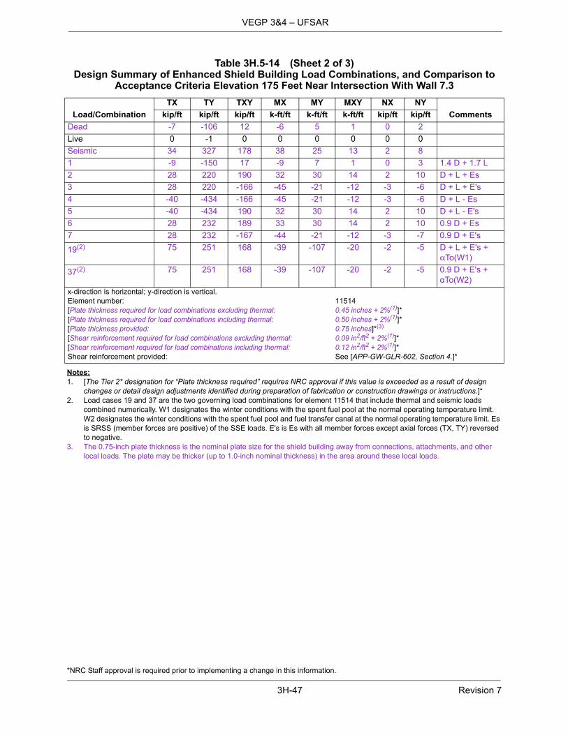
*NRC Staff approval is required prior to implementing a change in this information.
3H-47 Revision 7
VEGP 3&4 – UFSAR
Notes:1. [The Tier 2* designation for “Plate thickness required” requires NRC approval if this value is exceeded as a result of design
changes or detail design adjustments identified during preparation of fabrication or construction drawings or instructions.]*2. Load cases 19 and 37 are the two governing load combinations for element 11514 that include thermal and seismic loads
combined numerically. W1 designates the winter conditions with the spent fuel pool at the normal operating temperature limit. W2 designates the winter conditions with the spent fuel pool and fuel transfer canal at the normal operating temperature limit. Es is SRSS (member forces are positive) of the SSE loads. E's is Es with all member forces except axial forces (TX, TY) reversed to negative.
3. The 0.75-inch plate thickness is the nominal plate size for the shield building away from connections, attachments, and otherlocal loads. The plate may be thicker (up to 1.0-inch nominal thickness) in the area around these local loads.
Table 3H.5-14 (Sheet 2 of 3)Design Summary of Enhanced Shield Building Load Combinations, and Comparison to
Acceptance Criteria Elevation 175 Feet Near Intersection With Wall 7.3
Load/Combination
TX TY TXY MX MY MXY NX NY
Commentskip/ft kip/ft kip/ft k-ft/ft k-ft/ft k-ft/ft kip/ft kip/ft
Dead -7 -106 12 -6 5 1 0 2
Live 0 -1 0 0 0 0 0 0
Seismic 34 327 178 38 25 13 2 8
1 -9 -150 17 -9 7 1 0 3 1.4 D + 1.7 L
2 28 220 190 32 30 14 2 10 D + L + Es
3 28 220 -166 -45 -21 -12 -3 -6 D + L + E's
4 -40 -434 -166 -45 -21 -12 -3 -6 D + L - Es
5 -40 -434 190 32 30 14 2 10 D + L - E's
6 28 232 189 33 30 14 2 10 0.9 D + Es
7 28 232 -167 -44 -21 -12 -3 -7 0.9 D + E's
19(2) 75 251 168 -39 -107 -20 -2 -5 D + L + E's + αTo(W1)
37(2) 75 251 168 -39 -107 -20 -2 -5 0.9 D + E's + αTo(W2)
x-direction is horizontal; y-direction is vertical.Element number: 11514[Plate thickness required for load combinations excluding thermal: 0.45 inches + 2%(1)]*[Plate thickness required for load combinations including thermal: 0.50 inches + 2%(1)]*[Plate thickness provided: 0.75 inches]*(3)
[Shear reinforcement required for load combinations excluding thermal: 0.09 in2/ft2 + 2%(1)]*[Shear reinforcement required for load combinations including thermal: 0.12 in2/ft2 + 2%(1)]*Shear reinforcement provided: See [APP-GW-GLR-602, Section 4.]*
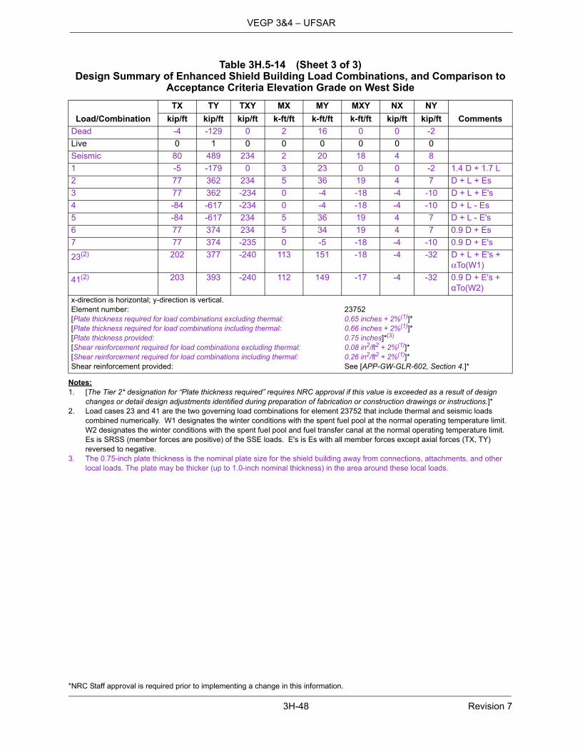
*NRC Staff approval is required prior to implementing a change in this information.
3H-48 Revision 7
VEGP 3&4 – UFSAR
Notes:1. [The Tier 2* designation for “Plate thickness required” requires NRC approval if this value is exceeded as a result of design
changes or detail design adjustments identified during preparation of fabrication or construction drawings or instructions.]*2. Load cases 23 and 41 are the two governing load combinations for element 23752 that include thermal and seismic loads
combined numerically. W1 designates the winter conditions with the spent fuel pool at the normal operating temperature limit. W2 designates the winter conditions with the spent fuel pool and fuel transfer canal at the normal operating temperature limit. Es is SRSS (member forces are positive) of the SSE loads. E's is Es with all member forces except axial forces (TX, TY) reversed to negative.
3. The 0.75-inch plate thickness is the nominal plate size for the shield building away from connections, attachments, and otherlocal loads. The plate may be thicker (up to 1.0-inch nominal thickness) in the area around these local loads.
Table 3H.5-14 (Sheet 3 of 3)Design Summary of Enhanced Shield Building Load Combinations, and Comparison to
Acceptance Criteria Elevation Grade on West Side
Load/Combination
TX TY TXY MX MY MXY NX NY
Commentskip/ft kip/ft kip/ft k-ft/ft k-ft/ft k-ft/ft kip/ft kip/ft
Dead -4 -129 0 2 16 0 0 -2
Live 0 1 0 0 0 0 0 0
Seismic 80 489 234 2 20 18 4 8
1 -5 -179 0 3 23 0 0 -2 1.4 D + 1.7 L
2 77 362 234 5 36 19 4 7 D + L + Es
3 77 362 -234 0 -4 -18 -4 -10 D + L + E's
4 -84 -617 -234 0 -4 -18 -4 -10 D + L - Es
5 -84 -617 234 5 36 19 4 7 D + L - E's
6 77 374 234 5 34 19 4 7 0.9 D + Es
7 77 374 -235 0 -5 -18 -4 -10 0.9 D + E's
23(2) 202 377 -240 113 151 -18 -4 -32 D + L + E's + αTo(W1)
41(2) 203 393 -240 112 149 -17 -4 -32 0.9 D + E's + αTo(W2)
x-direction is horizontal; y-direction is vertical.Element number: 23752[Plate thickness required for load combinations excluding thermal: 0.65 inches + 2%(1)]*[Plate thickness required for load combinations including thermal: 0.66 inches + 2%(1)]*[Plate thickness provided: 0.75 inches]*(3)
[Shear reinforcement required for load combinations excluding thermal: 0.08 in2/ft2 + 2%(1)]*[Shear reinforcement required for load combinations including thermal: 0.26 in2/ft2 + 2%(1)]*Shear reinforcement provided: See [APP-GW-GLR-602, Section 4.]*

*NRC Staff approval is required prior to implementing a change in this information.
3H-49 Revision 7
VEGP 3&4 – UFSAR
Note:1. Roof beams are not considered as reinforcement for the reinforced concrete roof. Ratio for conical roof beams is based on
demand and allowable stresses in psi.2. Built-up plate girders can be substituted for rolled shape. The section dimensions of the built-up plate girders are specified in
Figure 3H.5-11 Sheet 1.
Table 3H.5-15Shield Building Roof Reinforcement Ratio of Code Required Versus Provided
Critical SectionsStress
ComponentRequired
in2/ft
Provided(Minimum)
in2/ftReinforcement
Ratio
[Conical Roof Beams]* (1) Axial + Bending - [Radial Beams W36 X 395(2)]*
1.33
Shear - 8.33
[Conical Roof Near Tension Ring]*
Radial 1.80 [2.34]* 1.30
Hoop 4.31 [4.68]* 1.09
[Knuckle Region]* Vertical 1.49 [2.75]* 1.85
Radial 2.85 [3.55]* 1.25
Hoop 2.64 [3.12]* 1.18
[Compression Ring]* Vertical 1.24 [2.40]* 1.94
Radial 3.09 [3.56]* 1.15
Hoop 2.49 [3.12]* 1.25

*NRC Staff approval is required prior to implementing a change in this information.
3H-50 Revision 7
VEGP 3&4 – UFSAR
Figure 3H.2-1[General Layout of Auxiliary Building]*

*NRC Staff approval is required prior to implementing a change in this information.
3H-51 Revision 7
VEGP 3&4 – UFSAR
Figure 3H.5-1 (Sheet 1 of 3)[Nuclear Island Critical Sections
Plan at El. 135′-3″]*

*NRC Staff approval is required prior to implementing a change in this information.
3H-52 Revision 7
VEGP 3&4 – UFSAR
Figure 3H.5-1 (Sheet 2 of 3)[Nuclear Island Critical Sections
Plan at El. 180′-0″]*

*NRC Staff approval is required prior to implementing a change in this information.
3H-53 Revision 7
VEGP 3&4 – UFSAR
Figure 3H.5-1 (Sheet 3 of 3)[Nuclear Island Critical Sections
Section A-A]*
Security-Related Information, Withheld Under 10 CFR 2.390d

*NRC Staff approval is required prior to implementing a change in this information.
3H-54 Revision 7
VEGP 3&4 – UFSAR
Figure 3H.5-2 (Sheet 1 of 3)[Wall on Column Line 1]*

*NRC Staff approval is required prior to implementing a change in this information.
3H-55 Revision 7
VEGP 3&4 – UFSAR
Figure 3H.5-2 (Sheet 2 of 3)[Wall on Column Line 7.3]*

*NRC Staff approval is required prior to implementing a change in this information.
3H-56 Revision 7
VEGP 3&4 – UFSAR
Figure 3H.5-2 (Sheet 3 of 3)[Wall on Column Line L]*

*NRC Staff approval is required prior to implementing a change in this information.
3H-57 Revision 7
VEGP 3&4 – UFSAR
Figure 3H.5-3[Typical Reinforcement in Wall on Column Line 1]*
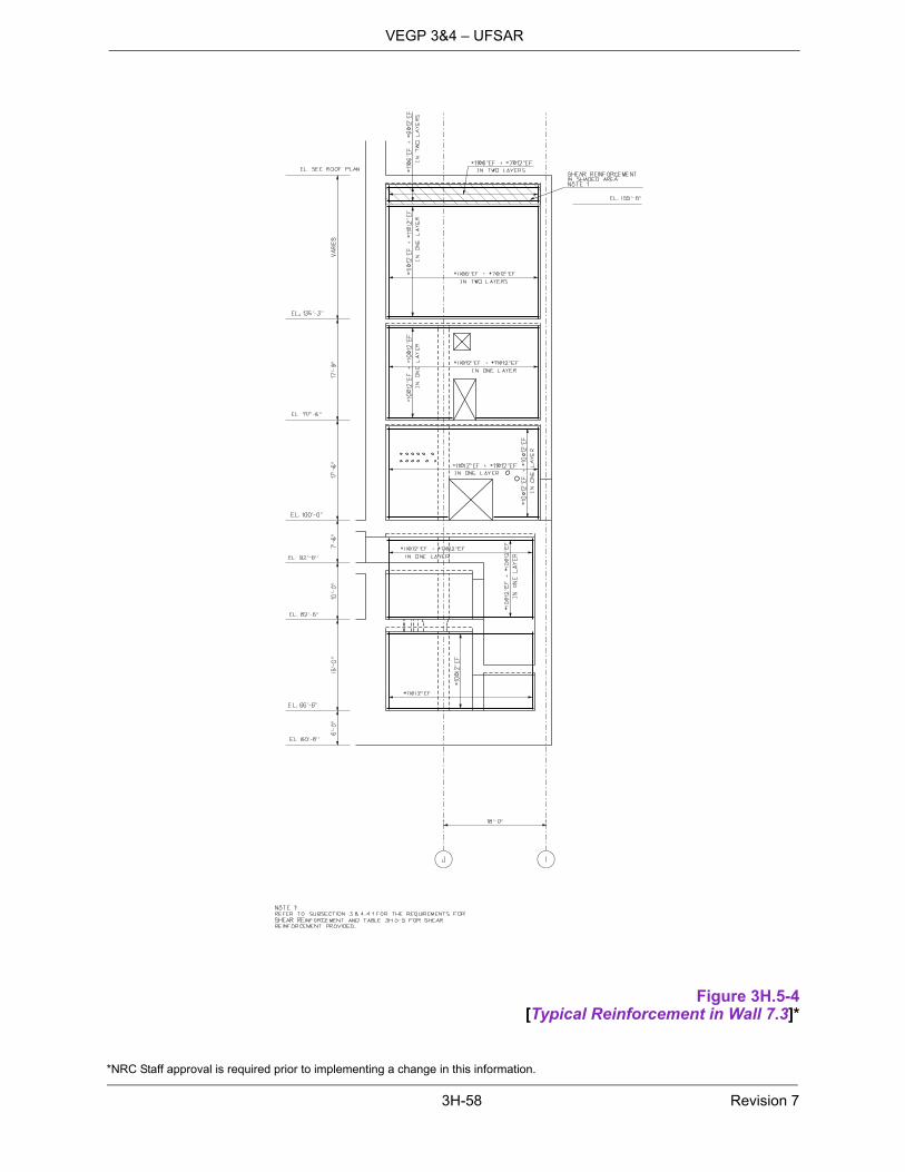
*NRC Staff approval is required prior to implementing a change in this information.
3H-58 Revision 7
VEGP 3&4 – UFSAR
Figure 3H.5-4[Typical Reinforcement in Wall 7.3]*
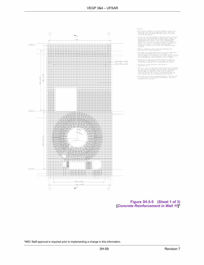
*NRC Staff approval is required prior to implementing a change in this information.
3H-59 Revision 7
VEGP 3&4 – UFSAR
Figure 3H.5-5 (Sheet 1 of 3)[Concrete Reinforcement in Wall 11]*

*NRC Staff approval is required prior to implementing a change in this information.
3H-60 Revision 7
VEGP 3&4 – UFSAR
Figure 3H.5-5 (Sheet 2 of 3)[Concrete Reinforcement Layers in Wall 11 (Looking East)]*

*NRC Staff approval is required prior to implementing a change in this information.
3H-61 Revision 7
VEGP 3&4 – UFSAR
Figure 3H.5-5 (Sheet 3 of 3)[Wall 11 at Main Steamline Anchor
Section A-A]*

*NRC Staff approval is required prior to implementing a change in this information.
3H-62 Revision 7
VEGP 3&4 – UFSAR
Figure 3H.5-6[Auxiliary Building
Typical Composite Floor]*

*NRC Staff approval is required prior to implementing a change in this information.
3H-63 Revision 7
VEGP 3&4 – UFSAR
Figure 3H.5-7[Typical Reinforcement and Connection to Shield Building]*

*NRC Staff approval is required prior to implementing a change in this information.
3H-64 Revision 7
VEGP 3&4 – UFSAR
Figure 3H.5-8[Auxiliary Building Operations Work Area
(Tagging Room) Ceiling]*

*NRC Staff approval is required prior to implementing a change in this information.
3H-65 Revision 7
VEGP 3&4 – UFSAR
Figure 3H.5-9 (Sheet 1 of 3)[Auxiliary Building Finned Floor]*

*NRC Staff approval is required prior to implementing a change in this information.
3H-66 Revision 7
VEGP 3&4 – UFSAR
Figure 3H.5-9 (Sheet 2 of 3)[Auxiliary Building Finned Floor]*

*NRC Staff approval is required prior to implementing a change in this information.
3H-67 Revision 7
VEGP 3&4 – UFSAR
Figure 3H.5-9 (Sheet 3 of 3)[Auxiliary Building Finned Floor]*
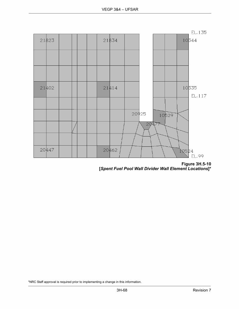
*NRC Staff approval is required prior to implementing a change in this information.
3H-68 Revision 7
VEGP 3&4 – UFSAR
Figure 3H.5-10[Spent Fuel Pool Wall Divider Wall Element Locations]*

*NRC Staff approval is required prior to implementing a change in this information.
3H-69 Revision 7
VEGP 3&4 – UFSAR
Figure 3H.5-11 (Sheet 1 of 6)[Design of Shield Building: Roof and Air Inlets]*
Security-Related Information, Withheld Under 10 CFR 2.390d

*NRC Staff approval is required prior to implementing a change in this information.
3H-70 Revision 7
VEGP 3&4 – UFSAR
Figure 3H.5-11 (Sheet 2 of 6)[Design of Shield Building: Concrete Detail at Tension Ring]*
Security-Related Information, Withheld Under 10 CFR 2.390d

*NRC Staff approval is required prior to implementing a change in this information.
3H-71 Revision 7
VEGP 3&4 – UFSAR
Figure 3H.5-11 (Sheet 3 of 6)[Design of Shield Building: Roof/Air Inlet Interface]*
Security-Related Information, Withheld Under 10 CFR 2.390d

*NRC Staff approval is required prior to implementing a change in this information.
3H-72 Revision 7
VEGP 3&4 – UFSAR
Figure 3H.5-11 (Sheet 4 of 6)[Design of Shield Building at Air Inlets]*
Security-Related Information, Withheld Under 10 CFR 2.390d

*NRC Staff approval is required prior to implementing a change in this information.
3H-73 Revision 7
VEGP 3&4 – UFSAR
Figure 3H.5-11 (Sheet 5 of 6)[Design of Shield Building:
Tank/Roof Interface Reinforcement]*
Security-Related Information, Withheld Under 10 CFR 2.390d
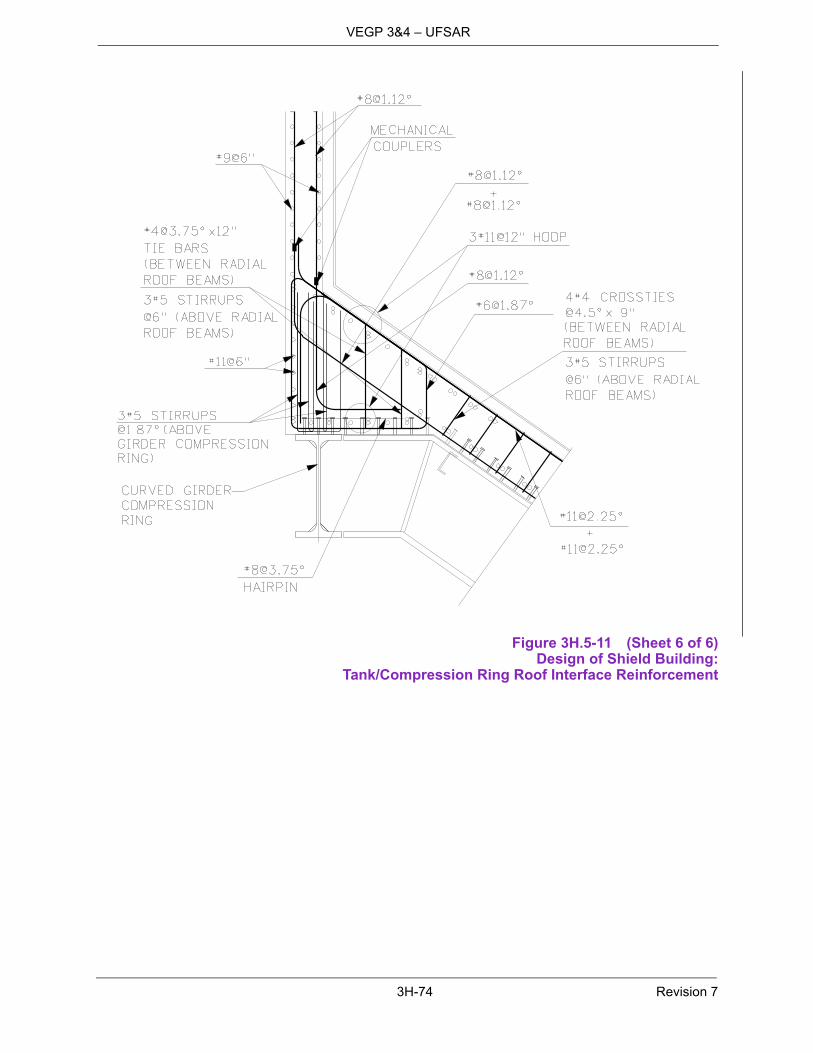
3H-74 Revision 7
VEGP 3&4 – UFSAR
Figure 3H.5-11 (Sheet 6 of 6)Design of Shield Building:
Tank/Compression Ring Roof Interface Reinforcement

*NRC Staff approval is required prior to implementing a change in this information.
3H-75 Revision 7
VEGP 3&4 – UFSAR
Figure 3H.5-12[Typical Reinforcement in Wall L]*

3H-76 Revision 7
VEGP 3&4 – UFSAR
Figure 3H.5-13Enhanced Shield Building Wall Panel Layout
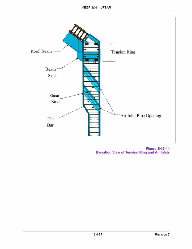
3H-77 Revision 7
VEGP 3&4 – UFSAR
Figure 3H.5-14Elevation View of Tension Ring and Air Inlets

3H-78 Revision 7
VEGP 3&4 – UFSAR
Figure 3H.5-15Shield Building Tension Ring
*NRC Staff approval is required prior to implementing a change in this information.
3H-79 Revision 7
VEGP 3&4 – UFSAR
For additional information, see Figure 6 of APP-GW-GLR-602 (Reference 1).
Figure 3H.5-16 (Sheet 1 of 2)[Design of Shield Building:
Surface Plates on Cylindrical Section – Developed View 90-270 Degrees]*
Security-Related Information, Withheld Under 10 CFR 2.390d

*NRC Staff approval is required prior to implementing a change in this information.
3H-80 Revision 7
VEGP 3&4 – UFSAR
For additional information, see Figure 6 of APP-GW-GLR-602 (Reference 1).
Figure 3H.5-16 (Sheet 2 of 2)[Design of Shield Building:
Surface Plates on Cylindrical Section – Developed View 270-90 Degrees]*
Security-Related Information, Withheld Under 10 CFR 2.390d

3I-1 Revision 7
VEGP 3&4 – UFSAR
Appendix 3I Evaluation for High Frequency Seismic Input
3I.1 Introduction
The seismic analysis and design of the AP1000 plant is based on the Certified Seismic Design Response Spectra (CSDRS) shown in Subsection 3.7.1.1. These spectra are based on Regulatory Guide 1.60 with an increase in the 25 hertz region. Ground Motion Response Spectra (GMRS) for some Central and Eastern United States rock sites show higher amplitude at high frequency than the CSDRS. Evaluations are described in this appendix for an envelope response spectra with high frequency for the seismic input. The resulting spectra of this site are shown in Figure 3I.1-1 and Figure 3I.1-2 and compare this hard rock high frequency (HRHF) envelope response spectra at the foundation level against the AP1000 CSDRS for both the horizontal and vertical directions for 5% damping. The HRHF envelope response spectra exceed the CSDRS for frequencies above about 15 Hz.
High frequency seismic input is generally considered to be non-damaging as described in Reference 1. The evaluation of the AP1000 nuclear island for the high frequency input is based on the analysis of a limited sample of structures, components, supports, and piping to demonstrate that the high frequency seismic response is non-damaging. The evaluation includes building structures, reactor pressure vessel and internals, primary component supports, primary loop nozzles, piping, and equipment.
This appendix describes the methodology and criteria used in the evaluation to confirm that the high frequency input is not damaging to equipment and structures qualified by analysis for the AP1000 CSDRS. It provides supplemental criteria for selection and testing of equipment whose function might be sensitive to high frequency. The results of the high frequency evaluation demonstrating that the AP1000 plant is qualified for this type of input are documented in a technical report (Reference 2). This report will provide a summary of the analysis and test results.
3I.2 High Frequency Seismic Input
Presented in Figures 3I.1-1 and 3I.1-2 is a comparison of the horizontal and vertical HRHF envelope response spectra and the AP1000 CSDRS. The HRHF envelope response spectra presented are calculated at foundation level (39.5' below grade), at the upper most competent material and treated as an outcrop for calculation purposes.
For each direction, the HRHF envelope response spectra exceed the design spectra in higher frequencies (greater than 15 Hz horizontal and 20 Hz vertical). The spectra are used for the HRHF envelope response spectra. If necessary, the HRHF envelope response spectra are enhanced at low frequencies so that HRHF envelope response spectra fully envelope all of the hard rock sites.
These HRHF envelope response spectra are further limited in that the shear wave velocity limitation is defined at the bottom of the basemat equal to or higher than 7,500 fps, while maintaining a shear wave velocity equal to or above 8,000 fps at the lower depths.
3I.3 NI Models Used To Develop High Frequency Response
The NI20 nuclear island model described in Appendix 3G is analyzed in ACS SASSI using the HRHF time histories applied at foundation level to obtain the motion at the base.
A modal analysis of the NI05 model for both the auxiliary and shield buildings and containment internal structure (CIS) has been performed for each of these regions. Specific areas within each wall or floor where out-of-plane modes, which may respond to either CSDRS or HRHF input (including structures with modes less than 33 Hz and between 33 Hz to 50 Hz), have been identified. The

3I-2 Revision 7
VEGP 3&4 – UFSAR
survey reveals that some regions, typically in the middle of a floor or wall, exhibit amplified behavior compared to the critical nodes at the corner and edge building locations. The amplified FRS for these regions is generated in addition to the typical set of critical nodes for building analysis by a single time history analysis of the NI05 building model subject to the HRHF time history input. Seismic response spectra for each of the “flexible” nodes are considered when selecting the pre-existing “group” spectra, which is the envelope of the entire floor in that area.
Evaluation of incoherent HRHF spectra has been performed. The CSDRS and HRHF seismic responses were compared with coherent and incoherent considerations at a number of locations in the nuclear island. There are some exceedances, mostly above the 15 hertz region, and these are typical of the plant comparative responses. The steel containment vessel (SCV) was excluded from the evaluation because the HRHF spectra at the base of the SCV are enveloped by the AP1000 CSDRS spectra at the base of the SCV.
Structures designed to the CSDRS input are adequately designed for the HRHF input because the HRHF coherent results are enveloped by the CSDRS results.
3I.4 Evaluation Methodology
The demonstration that the AP1000 nuclear power plant is qualified for the high frequency seismic response does not require the analysis of the total plant. The evaluations made are of representative systems, structures, and components, selected by screening, as potentially sensitive to high frequency input in locations where there were exceedances in the high frequency region. Acceptability of this sample is considered sufficient to demonstrate that the AP1000 is qualified.
The high frequency seismic analyses that are performed use time history or broadened response spectra. The analysis is not performed using the combination spectra of the CSDRS and the HRHF envelope response spectra. Separate analyses with each spectra are used.
The high frequency seismic analyses used the soil-structure interaction code ACS SASSI. The results presented in this report are based on the stochastic (multiple, statistical analyses) seismic incoherent soil-structure interaction analysis approach referred herein as the simulation approach.
The evaluations performed assess the ability of the system, structure, or component to maintain its safety function.
Supplementary analyses are performed as needed to show that high frequency floor response spectra exceedances are not damaging. These analyses can include: gap nonlinearities; material inelastic behavior; multi point response spectra analyses where the high frequency response excites a local part of the system. Tests on equipment are specified as needed where function cannot be demonstrated by analysis, or analysis is not appropriate.
3I.5 General Selection Screening Criteria
The following general screening criteria are used to identify representative AP1000 systems, structures, and components (SSCs) for the samples to be evaluated to demonstrate acceptability of the AP1000 nuclear power plant for the high frequency motion.
Select systems, structures, and components based on their importance to safety. This includes the review of component safety function for the SSE event and its potential failure modes due to an SSE. Those components whose failure modes would result in safe shutdown are excluded.

3I-3 Revision 7
VEGP 3&4 – UFSAR
Select systems, structures, and components that are located in areas of the plant thatexperience large high frequency seismic response.
Select systems, structures, and components that have significant modal response within theregion of high frequency amplification. Significance is defined by such items as modal mass;participation factor, stress and/or deflection.
Select systems, structures, and components that have significant stress as compared toallowable when considering load combinations that include seismic.
3I.6 Evaluation
In this section the portions of structures, the components, and the systems that are evaluated for the high frequency seismic response are identified. The sample to be evaluated, based on the screening criteria applicable to the SSCs consists of the following:
Building Structures
– Auxiliary Building – 3 locations
– Shield Building – 8 locations
– CIS – 2 locations
Primary Coolant Loop
– Reactor Vessel and Internals
– Primary Component Supports
– Reactor Coolant Loop Primary Equipment Nozzles
Piping Systems – ASME Class 1, 2, and 3 piping systems will be evaluated for the HRHFGMRS. This evaluation is within the scope of the piping DAC (see COL Information Item 3.9-7).
Electro-Mechanical Equipment – Equipment that is potentially sensitive to high frequencyinput (see Table 3I.6-1)
These structures, systems, and equipment are discussed in more detail in the sections that follow.
3I.6.1 Building Structures
Maintaining the NI buildings structural integrity is important to the safety of the plant. Representative portions of the buildings that are evaluated for the effect of high frequency input are selected based on those areas that can experience high seismic shear and moment loads due to the seismic event. Areas chosen are at the base of the shield building, in the vicinity of auxiliary building floors that have fundamental frequencies in the high frequency region, and the corners of the auxiliary building. Three locations are selected on the auxiliary building that reflect the bottom of a wall where the shear and moment would be large, a wall in the vicinity of a floor that is influenced by high frequency response, and a corner intersection of walls. Eight locations are evaluated on the shield building. Four at elevation 107' and four at elevation 211'. These locations are located on the east, west, north and south sides. The south-west wall of the refueling canal is evaluated since it is a representative wall on
3I-4 Revision 7
VEGP 3&4 – UFSAR
the refueling canal. The CA02 wall in the CIS building is evaluated since it is a representative wall associated with the IRWST.
The evaluation consists of a comparison of the loads from the high frequency input to those obtained from the AP1000 design spectra, shown in Figures 3I.1-1 and 3I.1-2, for these representative building structures. The NI building structures are considered qualified for the high frequency input if the seismic loads from the Regulatory Guide 1.60 (modified) envelope those from the high frequency input. If there is any exceedance, this is evaluated further to confirm that the existing design is adequate.
3I.6.2 Primary Coolant Loop
A failure within the reactor coolant loop could challenge the integrity of the reactor coolant pressure boundary. Therefore, it is chosen for evaluation. The components evaluated are as follows:
Reactor vessel and internals Reactor vessel supports Steam generator supports Reactor coolant loop primary equipment nozzles
The reactor vessel and internals are selected since they are important to safety and their analysis is representative of major primary components. The building structure below the reactor vessel supports is fairly stiff and there may be significant vertical amplification at the supports of the reactor pressure vessel. Further, reactor vessel internals have relatively complex structural systems including gap nonlinearities and sliding elements. Also, they may be sensitive to high frequency input as summarized below:
Vertical and horizontal modes of the upper internals and the reactor vessel modes are in therelatively high frequency range.
Additional high frequencies are associated with nonlinear impact
The evaluation consists of a comparison of the loads from the high frequency input to those obtained from the Regulatory Guide 1.60 (modified) input. Qualification is shown for the high frequency input if the seismic loads from the Regulatory Guide 1.60 (modified) envelope those from the high frequency input. If there is exceedance, then comparison is made for the combination of the seismic with the design basis pipe break loads and steady state loads. Qualification is then shown if the high frequency loads are relatively insignificant compared to the other loads, or there are no required design changes.
Maintaining the integrity of the reactor vessel and steam generator supports is important to preserving the primary component safety function. They are representative of supports on components, and see high loads.
The reactor coolant loop nozzles at the cold and hot leg interfaces of the reactor pressure vessel, reactor coolant pumps, and steam generators are important to include in the evaluation since these are critical areas of components.
The evaluation of the primary component supports and reactor coolant loop nozzles consists of a comparison of the loads from the high frequency input to those obtained from the Regulatory Guide 1.60 (modified) input. These items are considered qualified for the high frequency input if the seismic loads from the Regulatory Guide 1.60 (modified) envelope those from the high frequency input. If there is any exceedance, then an evaluation is made combining the high frequency loads with the other load components (e.g., thermal, pressure, dead) and a comparison made to the design loads. If
3I-5 Revision 7
VEGP 3&4 – UFSAR
the design loads envelope the load combinations that include the high frequency seismic input, then the nozzles and supports are considered qualified for the high frequency input.
3I.6.3 Piping Systems
ASME Class 1, 2, and 3 piping systems will be evaluated for the HRHF GMRS. This evaluation is within the scope of the piping DAC (see COL Information Item 3.9-7).
3I.6.4 Electrical and Electro-Mechanical Equipment
The groups of safety-related equipment considered for evaluation are those that may be sensitive to the high frequency input. This includes those cabinet-mounted equipment, field sensors, and appurtenants that may be sensitive to high frequency seismic inputs identified in Table 3I.6-1.
Sample safety-related cabinets have been identified that are typically sensitive to seismic input. Evaluations were performed to verify these cabinets do not have excessive seismic excitation on their mounted equipment, the cabinet designs do not require changes due to the high frequency input, and the cabinets will maintain their structural integrity during the high frequency input. Time history analyses of these cabinets were performed for both the Regulatory Guide 1.60 (modified) and the high frequency inputs so that comparisons can be made to their seismic response from both seismic inputs. This analytical study reported in APP-GW-GLR-115 (Reference 2) concluded that safety-related equipment may be screened.
The AP1000 HRHF screening program for determination and evaluation of potential high frequency sensitive equipment is in compliance with the NRC requirements in Section 4.0, “Identification and Evaluation of HF Sensitive Mechanical and Electrical Equipment/Components,” of COL/DC-ISG-1 (Reference 3). The AP1000 HRHF screening program is also consistent with the guidelines developed as part of an industry review document in the EPRI White Paper, “Seismic Screening of Components Sensitive to High Frequency Vibratory Motions” (Reference 4), transmitted to the NRC on June 28, 2007, for determining the safety-related equipment and components that may be HRHF sensitive, and screening procedures to ensure that any safety-related equipment and components sensitive to HRHF seismic excitation are screened out. This industry review of HF exceedance and further evaluations of SSCs performed by Westinghouse concluded that HRHF envelope response spectra are less harmful than the CSDRS except for the functionality of potential HRHF-sensitive components.
The AP1000 HRHF screening program is based on an HF evaluation study reported in APP-GW-GLR-115 (Reference 2). The HF evaluation study concluded that AP1000 In-Structure Response Spectra (ISRS) developed from the AP1000 CSDRS would, in the majority of cases, produce equipment stress results of the same magnitude or higher than the stress results produced from HRHF seismic excitation. The exception to this condition is when the dominant natural frequency of the equipment is in the HRHF exceedance range and there can be significantly more response because the frequency coincides with the input driving force. Under this condition, forces/stresses generated in the equipment could be due to the acceleration exceedance; therefore, the equipment will be subjected to HRHF seismic evaluation/testing to screen out equipment by verifying its performance and acceptability under HRHF excitation. Review of seismic test data for electrical and microprocessor based cabinets performed to generic and high frequency excitation concluded that seismic testing that peaks in the lower frequency range will produce larger displacements and velocities, and will result in higher stresses in the equipment.
The goal of the AP1000 HRHF screening program is to identify the potential safety-related equipment and components that have the potential to be HRHF-sensitive and show them to be acceptable for their specific application (screened-out). The AP1000 HRHF screening program is a two step process. The first step is an HRHF susceptibility review to identify potential high frequency sensitive
3I-6 Revision 7
VEGP 3&4 – UFSAR
safety-related equipment. The second step is the screened-out equipment process to demonstrate its acceptability for the HRHF seismic excitation. Evaluation of screened-in equipment as defined in COL/DC-ISG-1 (Reference 3) is not performed because all safety-related equipment that is screened-in will be eliminated or shown to be acceptable through a design change process.
For the AP1000 HRHF screening program, the following conditions must exist:
1. Plant-specific HRHF GMRS exceeds the AP1000 CSDRS in the high frequency range at 5% critical damping.
2. Safety-related equipment has potential failure modes involving change of state, chatter, signal change/drift, and connection problems.
Table 3I.6-2 is a list of potential HRHF-sensitive AP1000 safety-related equipment developed based on Table 3.11-1 of Section 3.11, “Environmental Qualification of Mechanical and Electrical Equipment.” The equipment in Table 3.2-3 of Section 3.2, “AP1000 Classification of Mechanical and Fluid Systems, Components, and Equipment,” and Table 3I.6-3 is not HRHF-sensitive. The structural integrity and operability of equipment in Table 3.2-3 and Table 3I.6-3 will not be impacted by the high frequency excitation.
The HRHF susceptibility review of AP1000 safety-related equipment is not performed for potential failure modes associated with mounting, connections, fasteners, joints, and structural interface. These potential failure modes are addressed through the seismic qualification of the safety-related equipment to the AP1000 ISRS testing performed in compliance with IEEE Standard 344-1987. The AP1000 ISRS qualification testing generates higher displacements and velocities than those resulting from HRHF seismic excitation since the AP1000 ISRS is controlled by the lower frequency range. The higher displacement, velocities, and accelerations will detect these equipment structural failure modes if they exist.
At locations where HRHF response spectra show exceedance of the CSDRS and there is a likelihood of equipment damage, further evaluations would be performed to verify that the existing qualification is adequate for equipment not high frequency sensitive, as listed in Table 3I.6-3, under the following conditions:
Safety-related equipment must have modes or natural frequencies in the range of interest.
Evaluation will apply the same acceptance criteria and methodologies used in CSDRS qualification.
To demonstrate acceptability for both CSDRS and HRHF testing, the test response spectra must envelop the CSDRS and HRHF spectra, respectively, with margin over the frequency range of interest in compliance with IEEE Standard 344-1987. In the event that the CSDRS and/or HRHF response spectra would be revised after the qualification program has been completed, a reconciliation effort would be performed to verify that the CSDRS and HRHF testing is still valid. The reconciliation effort may result in requalification activities and qualification documentation revisions.
High Frequency Screening Process – Step 1
The potential failure modes of high frequency sensitive component types and assemblies are important considerations in the high frequency program. The following are potential failure modes of high frequency sensitive components/equipment:
Inadvertent change of state Chatter Change in accuracy and drift in output signal or set-point

3I-7 Revision 7
VEGP 3&4 – UFSAR
Electrical connection failure or intermediacy (e.g., poor quality solder joints) Mechanical connection failure Mechanical misalignment/binding (e.g., latches, plungers) Fatigue failure (e.g., solder joints, ceramics, self-taping screws, spot welds) Improperly and unrestrained mounted components Inadequately secured/locked mechanical fasteners and connections
Components and equipment determined to have potential failure modes involve change of state, chatter, signal change/drift, and connection problems will be demonstrated to be acceptable through the performance of a supplemental high frequency screening test. Those high frequency sensitive components having failure modes associated with mounting, connections and fasteners, joints, and interface are considered to be acceptable as a result of the AP1000 ISRS qualification testing per IEEE Standard 344-1987 and/or require quality assurance inspection and process/design controls.
High Frequency Screening Process – Step 2
The HRHF susceptibility review is to verify that the subject equipment is capable of performing its safety-related function under HRHF seismic excitation. All AP1000 safety-related equipment will be qualified to the AP1000 ISRS, and the dominant natural frequencies of the equipment will be determined. The EPRI White Paper (Reference 4) identifies the following three evaluation methods to demonstrate that potential HRHF-sensitive safety-related equipment is not HRHF vulnerable:
1. Existing seismic qualification test data for potential high frequency sensitive equipmentshould be reviewed for applicability and adequacy of the test method to demonstratesufficient high frequency content.
2. Systems/circuits containing potentially sensitive items should be reviewed for inappropriate/unacceptable system actions due to assumed change of state, contact chatter/intermittency,set point drifts, or loss of calibration.
3. HRHF vibration screening test is conducted to identify any HRHF sensitivities/abnormalitiesof the components. Several conventional test methods are recommended.
The first and third evaluation methods are part of the AP1000 HRHF screening program and are further detailed below. The AP1000 HRHF seismic screening evaluation will employ the AP1000 HRHF envelope response spectra as input in verifying potential HF sensitive safety-related equipment is not vulnerable to HRHF seismic excitation. Additional seismic test margin will be introduced into the HRHF seismic screening evaluation as needed.
Method 1: Review of Seismic Test Data
Available seismic test data can be used for AP1000 HRHF plant applications when:
Seismic qualification testing performed on potential HRHF-sensitive safety-related equipmentmeets as a minimum the AP1000 ISRS in compliance with IEEE Standard 344-1987.
Safe shutdown earthquake (SSE) test had sufficient energy content in the HRHF region toverify that the safety-related equipment is not vulnerable to HRHF seismic excitation.
No additional seismic testing is required for safety-related equipment previously tested and whose qualification level envelops the HRHF required response spectra (RRS).
IEEE Standard 344-1987 provides guidance to ensure that the seismic test input is generated and in compliance with the frequency range of interest. To demonstrate acceptability for frequency content, it is necessary to show that the frequency content of the test waveform is at least as broad as the

3I-8 Revision 7
VEGP 3&4 – UFSAR
frequency content of the amplified region of the RRS except at the low frequencies where non-enveloping is permitted under certain conditions (refer to IEEE Standard 344-1987 subclauses 7.6.3.1(10) and 7.6.3.1(13)). An evaluation of the test input waveform should be conducted per IEEE Standard 344-1987 Annex B to verify the test data has sufficient content over the frequency range of interest throughout the input time history. If an evaluation of the test input is performed, and the data demonstrates sufficient frequency content in the high frequency range throughout the time history, then the data is acceptable.
Method 3: HRHF Screening Test
The HRHF screening test is a supplemental test to the required seismic qualification methods performed in accordance with IEEE Standard 344-1987 for those plants that have high frequency exceedance of the AP1000 CSDRS. The purpose of the HRHF screening test is to demonstrate that the potential HRHF-sensitive safety-related equipment will perform its safety-related function as required under HRHF seismic excitation. The HRHF screening test is performed in conjunction with the AP1000 ISRS seismic qualification testing, or it is performed as a supplemental test after completion of the AP1000 ISRS seismic qualification testing. The AP1000 ISRS and HRHF test input time histories have 30-second durations with frequency content up to the cutoff frequency developed in accordance with subclause 7.6.3 (Multiple-Frequency Tests) and Annex B (Frequency Content and Stationarity) of IEEE Standard 344-1987. During the AP1000 ISRS and HRHF testing, the equipment will be functional and monitored to verify the safety-related function was demonstrated. Screening testing will be performed using HRHF response spectra as defined in the EPRI White Paper (Reference 4) when AP1000 HRHF inputs are not available. The HRHF response spectra will be generated based on the 5g and 15g peak spectral acceleration at 5% critical damping in the 25 Hz to 50 Hz frequency range. If the HRHF screening test cannot demonstrate the equipment to be acceptable, then the safety-related equipment will be removed or modified and additional testing or justification will be required.
The AP1000 safety-related equipment will be seismic qualified to the AP1000 ISRS associated with the mounting location of the equipment as a minimum. Seismic qualification testing will consist of five AP1000 ISRS operating basis earthquakes (OBEs) followed by one SSE as a minimum. The OBE level will be at least one-half the SSE level. The OBE testing is used to vibration age and address low-cycle fatigue of equipment prior to SSE testing. Cyclic fatiguing of equipment for HRHF exceedance area is adequately addressed by performing five OBE (one-half the SSE) and a minimum of one SSE seismic test runs in compliance with IEEE Standard 344-1987 prior to performing the supplemental HRHF screening test. Additional OBE testing in the high frequency exceedance range is adequately addressed by the demonstration that the peak stress cycles required for five one-half SSE events using the AP1000 HRHF ISRS are equivalent to or enveloped by the peak stress cycles resulting from five one-half SSE events and one full SSE event using the AP1000 CSD ISRS (Reference 5).
The test results of AP1000 seismic qualification programs with multiple operational states (for example, relays have three possible operational states: de-energized, energized, and change of state) will be used to determine the most sensitive equipment electrical operational state. The HRHF test run is performed on the equipment in its most sensitive electrical operational state to demonstrate its safety-related function under HRHF seismic excitation. If this is not possible, additional HRHF screening tests will be performed as needed to address the other most sensitive electrical operation states.
3I.7 References
1. EPRI Draft White Paper, “Considerations for NPP Equipment and Structures Subjected toResponse Levels Caused by High Frequency Ground Motions,” Transmitted to NRCMarch 19, 2007.

3I-9 Revision 7
VEGP 3&4 – UFSAR
2. APP-GW-GLR-115, “Effect of High Frequency Seismic Content on SSCs,” WestinghouseElectric Company LLC.
3. COL/DC-ISG-1, “Interim Staff Guidance on Seismic Issues of High Frequency GroundMotion,” May 19, 2008.
4. EPRI White Paper, “Seismic Screening of Components Sensitive to High FrequencyVibratory Motions,” June 2007.
5. Letter, R. Sisk (Westinghouse) to NRC, “AP1000 Response to Request for AdditionalInformation (SRP3),” DCP/NRC2396, March 5, 2009.

3I-10 Revision 7
VEGP 3&4 – UFSAR
Table 3I.6-1Potential High Frequency Sensitive Equipment List
• Equipment or components with moving parts and required to perform a switching function during the seismicevent (e.g., circuit breakers, contactors, auxiliary switches, molded case circuit breakers, motor control centerstarters, and pneumatic control assemblies)
• Components with moving parts that may bounce or chatter such as relays and actuation devices (e.g., shunt trips)
• Unrestrained components
• Potentiometers
• Process switches and sensors (e.g., pressure/differential pressure, temperature, level, limit/position, and flow)
• Components with accuracy requirements that may drift due to seismic loading
• Interfaces such as secondary contacts
– Connectors and connections (including circuit board connections for digital and analog equipment)
3I-11 Revision 7
VEGP 3&4 – UFSAR
Table 3I.6-2 (Sheet 1 of 22)List of Potential High Frequency Sensitive
AP1000 Safety-Related electrical and Electro-mechanical Equipment
DescriptionAP1000
Tag Number
Batteries
IDSA 125V 60 Cell Battery 1A IDSA-DB-1A
IDSA 125V 60 Cell Battery 1B IDSA-DB-1B
IDSB 125V 60 Cell Battery 1A IDSB-DB-1A
IDSB 125V 60 Cell Battery 1B IDSB-DB-1B
IDSB 125V 60 Cell Battery 2A IDSB-DB-2A
IDSB 125V 60 Cell Battery 2B IDSB-DB-2B
IDSC 125V 60 Cell Battery 1A IDSC-DB-1A
IDSC 125V 60 Cell Battery 1B IDSC-DB-1B
IDSC 125V 60 Cell Battery 2A IDSC-DB-2A
IDSC 125V 60 Cell Battery 2B IDSC-DB-2B
IDSD 125V 60 Cell Battery 1A IDSD-DB-1A
IDSD 125V 60 Cell Battery 1B IDSD-DB-1B
Spare 125V 60 Cell Battery 1A IDSS-DB-1A
Spare 125V 60 Cell Battery 1B IDSS-DB-1B
Battery Chargers
IDSA Battery Charger IDSA-DC-1
IDSB Battery Charger IDSB-DC-1
IDSB Battery Charger 2 IDSB-DC-2
IDSC Battery Charger 1 IDSC-DC-1
IDSC Battery Charger 2 IDSC-DC-2
IDSD Battery Charger IDSD-DC-1
Spare Battery Charger IDSS-DC-1
Distribution Panels
IDSA 250 Vdc Dist Panel IDSA-DD-1
IDSB 250 Vdc Dist Panel IDSB-DD-1
IDSC 250 Vdc Dist Panel IDSC-DD-1
IDSD 250 Vdc Dist Panel IDSD-DD-1
IDSA 120 Vac Dist Panel 1 IDSA-EA-1
IDSA 120 Vac Dist Panel 2 IDSA-EA-2
IDSB 120 Vac Dist Panel 1 IDSB-EA-1
IDSB 120 Vac Dist Panel 2 IDSB-EA-2
IDSB 120 Vac Dist Panel 3 IDSB-EA-3
IDSC 120 Vac Dist Panel 1 IDSC-EA-1
IDSC 120 Vac Dist Panel 2 IDSC-EA-2
IDSC 120 Vac Dist Panel 3 IDSC-EA-3
IDSD 120 Vac Dist Panel 1 IDSD-EA-1
IDSD 120 Vac Dist Panel 2 IDSD-EA-2

3I-12 Revision 7
VEGP 3&4 – UFSAR
Fuse Panels
IDSA Fuse Panel IDSA-EA-4
IDSA Battery Monitor Fuse Panel IDSA-EA-5
IDSB Fuse Panel IDSB-EA-4
IDSB Fuse Panel IDSB-EA-5
IDSB Fuse Panel IDSB-EA-6
IDSB Battery Monitor Fuse Panel IDSB-EA-7
IDSB Battery Monitor Fuse Panel IDSB-EA-8
IDSC Fuse Panel IDSC-EA-4
IDSC Fuse Panel IDSC-EA-5
IDSC Fuse Panel IDSC-EA-6
IDSC Battery Monitor Fuse Panel IDSC-EA-7
IDSC Battery Monitor Fuse Panel IDSC-EA-8
IDSD Fuse Panel IDSD-EA-4
IDSD Battery Monitor Fuse Panel IDSD-EA-5
IDSS Battery Monitor Fuse Panel IDSS-EA-1
Transfer Switches
IDSA Fused Transfer Switch Box 1 IDSA-DF-1
IDSB Fused Transfer Switch Box 1 IDSB-DF-1
IDSB Fused Transfer Switch Box 2 IDSB-DF-2
IDSC Fused Transfer Switch Box 1 IDSC-DF-1
IDSC Fused Transfer Switch Box 2 IDSC-DF-2
IDSD Fused Transfer Switch Box 1 IDSD-DF-1
IDSS Fused Transfer Switch Box 1 IDSS-DF-1
IDSS Spare Battery Termination Box IDSS–DF-3
Motor Control Centers
IDSA 250 Vdc MCC IDSA-DK-1
IDSB 250 Vdc MCC IDSB-DK-1
IDSC 250 Vdc MCC IDSC-DK-1
IDSD 250 Vdc MCC IDSD-DK-1
Switchboards
IDSA 250 Vdc Switchboard 1 IDSA-DS-1
IDSB 250 Vdc Switchboard 1 IDSB-DS-1
IDSB 250 Vdc Switchboard 2 IDSB-DS-2
IDSC 250 Vdc Switchboard 1 IDSC-DS-1
IDSC 250 Vdc Switchboard 2 IDSC-DS-2
IDSD 250 Vdc Switchboard 1 IDSD-DS-1
Table 3I.6-2 (Sheet 2 of 22)List of Potential High Frequency Sensitive
AP1000 Safety-Related electrical and Electro-mechanical Equipment
DescriptionAP1000
Tag Number

3I-13 Revision 7
VEGP 3&4 – UFSAR
Transformers
IDSA Regulating Transformer 1 IDSA-DT-1
IDSB Regulating Transformer 1 IDSB-DT-1
IDSC Regulating Transformer 1 IDSC-DT-1
IDSD Regulating Transformer 1 IDSD-DT-1
Inverters
IDSA Inverter IDSA-DU-1
IDSB Inverter 1 IDSB-DU-1
IDSB Inverter 2 IDSB-DU-2
IDSC Inverter 1 IDSC-DU-1
IDSC Inverter 2 IDSC-DU-2
IDSD Inverter IDSD-DU-1
Switchgear
RCP 1A 6900V Switchgear 31 ECS-ES-31
RCP 1A 6900V Switchgear 32 ECS-ES-32
RCP 2A 6900V Switchgear 51 ECS-ES-51
RCP 2A 6900V Switchgear 52 ECS-ES-52
RCP 1B 6900V Switchgear 41 ECS-ES-41
RCP 1B 6900V Switchgear 42 ECS-ES-42
RCP 2B 6900V Switchgear 61 ECS-ES-61
RCP 2B 6900V Switchgear 62 ECS-ES-62
Junction Box Division A PMS-EJ-001A
Junction Box Division B PMS-EJ-001B
Junction Box Division C PMS-EJ-001C
Junction Box Division D PMS-EJ-001D
Junction Box Division A PMS-EJ-002A
Junction Box Division B PMS-EJ-002B
Junction Box Division C PMS-EJ-002C
Junction Box Division D PMS-EJ-002D
Reactor Trip Switchgear PMS-JD-RTSA01
Reactor Trip Switchgear PMS-JD-RTSA02
Reactor Trip Switchgear PMS-JD-RTSB01
Reactor Trip Switchgear PMS-JD-RTSB02
Reactor Trip Switchgear PMS-JD-RTSC01
Reactor Trip Switchgear PMS-JD-RTSC02
Reactor Trip Switchgear PMS-JD-RTSD01
Reactor Trip Switchgear PMS-JD-RTSD02
Table 3I.6-2 (Sheet 3 of 22)List of Potential High Frequency Sensitive
AP1000 Safety-Related electrical and Electro-mechanical Equipment
DescriptionAP1000
Tag Number

3I-14 Revision 7
VEGP 3&4 – UFSAR
Level Transmitters
Core Makeup Tank A Narrow Range PXS-JE-LE011A / PXS-JE-LT011A
Core Makeup Tank A Narrow Range PXS-JE-LE011B / PXS-JE-LT011B
Core Makeup Tank A Narrow Range PXS-JE-LE011C / PXS-JE-LT011C
Core Makeup Tank A Narrow Range PXS-JE-LE011D / PXS-JE-LT011D
Core Makeup Tank B Narrow Range PXS-JE-LE012A / PXS-JE-LT012A
Core Makeup Tank B Narrow Range PXS-JE-LE012B / PXS-JE-LT012B
Core Makeup Tank B Narrow Range PXS-JE-LE012C / PXS-JE-LT012C
Core Makeup Tank B Narrow Range PXS-JE-LE012D / PXS-JE-LT012D
Core Makeup Tank A Narrow Range PXS-JE-LE013A / PXS-JE-LT013A
Core Makeup Tank A Narrow Range PXS-JE-LE013B / PXS-JE-LT013B
Core Makeup Tank A Narrow Range PXS-JE-LE013C / PXS-JE-LT013C
Core Makeup Tank A Narrow Range PXS-JE-LE013D / PXS-JE-LT013D
Core Makeup Tank B Narrow Range PXS-JE-LE014A / PXS-JE-LT014A
Core Makeup Tank B Narrow Range PXS-JE-LE014B / PXS-JE-LT014B
Core Makeup Tank B Narrow Range PXS-JE-LE014C / PXS-JE-LT014C
Core Makeup Tank B Narrow Range PXS-JE-LE014D / PXS-JE-LT014D
Containment Floodup Level PXS-JE-LE050 / PXS-JE-LT050
Containment Floodup Level PXS-JE-LE051 / PXS-JE-LT051
Containment Floodup Level PXS-JE-LE052 / PXS-JE-LT052
Neutron Detectors
Source Range Neutron Detector RXS-JE-NE001A
Source Range Neutron Detector RXS-JE-NE001B
Source Range Neutron Detector RXS-JE-NE001C
Source Range Neutron Detector RXS-JE-NE001D
Intermediate Range Neutron Detector RXS-JE-NE002A
Intermediate Range Neutron Detector RXS-JE-NE002B
Intermediate Range Neutron Detector RXS-JE-NE002C
Intermediate Range Neutron Detector RXS-JE-NE002D
Power Range Neutron Detector (Lower) RXS-JE-NE003A
Power Range Neutron Detector (Lower) RXS-JE-NE003B
Power Range Neutron Detector (Lower) RXS-JE-NE003C
Power Range Neutron Detector (Lower) RXS-JE-NE003D
Power Range Neutron Detector (Upper) RXS-JE-NE004A
Power Range Neutron Detector (Upper) RXS–JE-NE004B
Power Range Neutron Detector (Upper) RXS-JE-NE004C
Power Range Neutron Detector (Upper) RXS-JE-NE004D
Table 3I.6-2 (Sheet 4 of 22)List of Potential High Frequency Sensitive
AP1000 Safety-Related electrical and Electro-mechanical Equipment
DescriptionAP1000
Tag Number
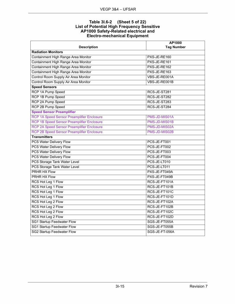
3I-15 Revision 7
VEGP 3&4 – UFSAR
Radiation Monitors
Containment High Range Area Monitor PXS-JE-RE160
Containment High Range Area Monitor PXS-JE-RE161
Containment High Range Area Monitor PXS-JE-RE162
Containment High Range Area Monitor PXS-JE-RE163
Control Room Supply Air Area Monitor VBS-JE-RE001A
Control Room Supply Air Area Monitor VBS-JE-RE001B
Speed Sensors
RCP 1A Pump Speed RCS-JE-ST281
RCP 1B Pump Speed RCS-JE-ST282
RCP 2A Pump Speed RCS-JE-ST283
RCP 2B Pump Speed RCS-JE-ST284
Speed Sensor Preamplifier
RCP 1A Speed Sensor Preamplifier Enclosure PMS-JD-MIS01A
RCP 1B Speed Sensor Preamplifier Enclosure PMS-JD-MIS01B
RCP 2A Speed Sensor Preamplifier Enclosure PMS-JD-MIS02A
RCP 2B Speed Sensor Preamplifier Enclosure PMS-JD-MIS02B
Transmitters
PCS Water Delivery Flow PCS-JE-FT001
PCS Water Delivery Flow PCS-JE-FT002
PCS Water Delivery Flow PCS-JE-FT003
PCS Water Delivery Flow PCS-JE-FT004
PCS Storage Tank Water Level PCS-JE-LT010
PCS Storage Tank Water Level PCS-JE-LT011
PRHR HX Flow PXS-JE-FT049A
PRHR HX Flow PXS-JE-FT049B
RCS Hot Leg 1 Flow RCS-JE-FT101A
RCS Hot Leg 1 Flow RCS-JE-FT101B
RCS Hot Leg 1 Flow RCS-JE-FT101C
RCS Hot Leg 1 Flow RCS-JE-FT101D
RCS Hot Leg 2 Flow RCS-JE-FT102A
RCS Hot Leg 2 Flow RCS-JE-FT102B
RCS Hot Leg 2 Flow RCS-JE-FT102C
RCS Hot Leg 2 Flow RCS-JE-FT102D
SG1 Startup Feedwater Flow SGS-JE-FT055A
SG1 Startup Feedwater Flow SGS-JE-FT055B
SG2 Startup Feedwater Flow SGS-JE-FT-056A
Table 3I.6-2 (Sheet 5 of 22)List of Potential High Frequency Sensitive
AP1000 Safety-Related electrical and Electro-mechanical Equipment
DescriptionAP1000
Tag Number

3I-16 Revision 7
VEGP 3&4 – UFSAR
SG2 Startup Feedwater Flow SGS-JE-FT056BMCR Air Delivery Line Flow Rate – A VES-JE-FT003AMCR Air Delivery Line Flow Rate – B VES-JE-FT003BPlant Vent Flow VFS-JE-FT105IRWST Wide Range Level PXS-JE-LT046IRWST Wide Range Level PXS-JE-LT047IRWST Wide Range Level PXS-JE-LT048IRWST Lower Narrow Range Level PXS-JE-LT066IRWST Lower Narrow Range Level PXS-JE-LT067IRWST Lower Narrow Range Level PXS-JE-LT068IRWST Lower Narrow Range Level PXS-JE-LT069RCS Hot Leg Water Level RCS-JE-LT160ARCS Hot Leg Water Level RCS-JE-LT160BPZR Level RCS-JE-LT195APZR Level RCS-JE-LT195BPZR Level RCS-JE-LT195CPZR Level RCS-JE-LT195DSG1 Narrow Range Level SGS-JE-LT001SG1 Narrow Range Level SGS-JE-LT002SG1 Narrow Range Level SGS-JE-LT003SG1 Narrow Range Level SGS-JE-LT004SG2 Narrow Range Level SGS-JE-LT005SG2 Narrow Range Level SGS-JE-LT006SG2 Narrow Range Level SGS-JE-LT007SG2 Narrow Range Level SGS-JE-LT008SG1 Wide Range Level SGS-JE-LT011SG1 Wide Range Level SGS-JE-LT012SG1 Wide Range Level SGS-JE-LT015SG1 Wide Range Level SGS-JE-LT016SG2 Wide Range Level SGS-JE-LT013SG2 Wide Range Level SGS-JE-LT014SG2 Wide Range Level SGS-JE-LT017SG2 Wide Range Level SGS-JE-LT018Spent Fuel Pool Level SFS-JE-LT019ASpent Fuel Pool Level SFS-JE-LT019BSpent Fuel Pool Level SFS-JE-LT019CWLS Auxiliary Building RCA Floodup Level WLS-JE-LT400AWLS Auxiliary Building RCA Floodup Level WLS-JE-LT400BAir Storage Tank Pressure – A VES-JE-PT001AAir Storage Tank Pressure – B VES-JE-PT001B
Table 3I.6-2 (Sheet 6 of 22)List of Potential High Frequency Sensitive
AP1000 Safety-Related electrical and Electro-mechanical Equipment
DescriptionAP1000
Tag Number

3I-17 Revision 7
VEGP 3&4 – UFSAR
Containment Pressure Normal Range PCS-JE-PT005
Containment Pressure Normal Range PCS-JE-PT006
Containment Pressure Normal Range PCS-JE-PT007
Containment Pressure Normal Range PCS-JE-PT008
Containment Pressure Extended Range PCS-JE-PT012
Containment Pressure Extended Range PCS-JE-PT013
Containment Pressure Extended Range PCS-JE-PT014
RCS Wide Range Pressure RCS-JE-PT140A
RCS Wide Range Pressure RCS-JE-PT140B
RCS Wide Range Pressure RCS-JE-PT140C
RCS Wide Range Pressure RCS-JE-PT140D
PZR Pressure RCS-JE-PT191A
PZR Pressure RCS-JE-PT191B
PZR Pressure RCS-JE-PT191C
PZR Pressure RCS-JE-PT191D
Main Steam Line SG1 Pressure SGS-JE-PT030
Main Steam Line SG1 Pressure SGS-JE-PT031
Main Steam Line SG1 Pressure SGS-JE-PT032
Main Steam Line SG1 Pressure SGS-JE-PT033
Main Steam Line SG2 Pressure SGS-JE-PT034
Main Steam Line SG2 Pressure SGS-JE-PT035
Main Steam Line SG2 Pressure SGS-JE-PT036
Main Steam Line SG2 Pressure SGS-JE-PT037
Main Control Room Differential Pressure VES-JE-PDT004A
Main Control Room Differential Pressure VES-JE-PDT004B
Protection and Safety Monitoring Systems
MCR/RSW Transfer Switch Panel OCS-JW-001
Bistable Coincident Logic Cabinet 01 Division A PMS-JD-BCCA01
Bistable Coincident Logic Cabinet 02 Division A PMS-JD-BCCA02
Bistable Coincident Logic Cabinet 01 Division B PMS-JD-BCCB01
Bistable Coincident Logic Cabinet 02 Division B PMS-JD-BCCB02
Bistable Coincident Logic Cabinet 01 Division C PMS-JD-BCCC01
Bistable Coincident Logic Cabinet 02 Division C PMS-JD-BCCC02
Bistable Coincident Logic Cabinet 01 Division D PMS-JD-BCCD01
Bistable Coincident Logic Cabinet 02 Division D PMS-JD-BCCD02
Table 3I.6-2 (Sheet 7 of 22)List of Potential High Frequency Sensitive
AP1000 Safety-Related electrical and Electro-mechanical Equipment
DescriptionAP1000
Tag Number

3I-18 Revision 7
VEGP 3&4 – UFSAR
Integrated Logic Cabinet 01 Division A PMS-JD-ILCA01
Integrated Logic Cabinet 02 Division A PMS-JD-ILCA02
Integrated Logic Cabinet 03 Division A PMS-JD-ILCA03
Integrated Logic Cabinet 01 Division B PMS-JD-ILCB01
Integrated Logic Cabinet 02 Division B PMS-JD-ILCB02
Integrated Logic Cabinet 03 Division B PMS-JD-ILCB03
Integrated Logic Cabinet 04 Division B PMS-JD-ILCB04
Integrated Logic Cabinet 01 Division C PMS-JD-ILCC01
Integrated Logic Cabinet 02 Division C PMS-JD-ILCC02
Integrated Logic Cabinet 01 Division D PMS-JD-ILCD01
Integrated Logic Cabinet 02 Division D PMS-JD-ILCD02
Integrated Logic Cabinet 03 Division D PMS-JD-ILCD03
Integrated Logic Cabinet 04 Division D PMS-JD-ILCD04
Maintenance and Test Cabinet Division A PMS-JD-MTCA01
Maintenance and Test Cabinet Division B PMS-JD-MTCB01
Maintenance and Test Cabinet Division C PMS-JD-MTCC01
Maintenance and Test Cabinet Division D PMS-JD-MTCD01
Nuclear Instrumentation Cabinet Division A PMS-JD-NICA01
Nuclear Instrumentation Cabinet Division B PMS-JD-NICB01
Nuclear Instrumentation Cabinet Division C PMS-JD-NICC01
Nuclear Instrumentation Cabinet Division D PMS-JD-NICD01
Qualified Data Processing System Cabinet Division B PMS-JD-QDPB01
Qualified Data Processing System Cabinet Division C PMS-JD-QDPC01
Division A Squib Valve Controller Cabinet PMS-JD-SVCA01
Division B Squib Valve Controller Cabinet PMS-JD-SVCB01
Division C Squib Valve Controller Cabinet PMS-JD-SVCC01
Division D Squib Valve Controller Cabinet PMS-JD-SVCD01
Source Range Neutron Flux Preamplifier Panel A PMS-JW-005A
Source Range Neutron Flux Preamplifier Panel B PMS-JW-005B
Source Range Neutron Flux Preamplifier Panel C PMS-JW-005C
Source Range Neutron Flux Preamplifier Panel D PMS-JW-005D
Intermediate Range Neutron Flux Preamplifier Panel A PMS-JW-006A
Intermediate Range Neutron Flux Preamplifier Panel B PMS-JW-006B
Intermediate Range Neutron Flux Preamplifier Panel C PMS-JW-006C
Intermediate Range Neutron Flux Preamplifier Panel D PMS-JW-006D
Table 3I.6-2 (Sheet 8 of 22)List of Potential High Frequency Sensitive
AP1000 Safety-Related electrical and Electro-mechanical Equipment
DescriptionAP1000
Tag Number

3I-19 Revision 7
VEGP 3&4 – UFSAR
Main Control Room
Operator Workstation A N/A
Operator Workstation B N/A
Supervisor Workstation N/A
Switch Station (Including Switches) N/A
Qualified Safety Display Division A PMS-JD-QSPA01
Qualified Safety Display Division B PMS-JD-QSPB01
Qualified Safety Display Division C PMS-JD-QSPC01
Qualified Safety Display Division D PMS-JD-QSPD01
MCR Load Shed Panel 1 VES-EP-01
MCR Load Shed Panel 2 VES-EP-02
Active Valves
Containment Isolation – Air Out
Solenoid Valve CAS-PL-V014-S
Limit Switch CAS-PL-V014-L
Containment Isolation – Inlet
Limit Switch CCS-PL-V200-L
Motor Operator CCS-PL-V200-M
Containment Isolation – Outlet
Limit Switch CCS-PL-V207-L
Motor Operator CCS-PL-V207-M
Containment Isolation – Outlet
Limit Switch CCS-PL-V208-L
Motor Operator CCS-PL-V208-M
RCS Purification Stop Valve
Limit Switch CVS-PL-V001-L
Motor Operator CVS-PL-V001-M
RCS Purification Stop Valve
Limit Switch CVS-PL-V002-L
Motor Operator CVS-PL-V002-M
RCS Letdown Stop Valve
Limit Switch CVS-PL-V003-L
Motor Operator CVS-PL-V003-M
WLS Letdown IRC Isolation
Limit Switch CVS-PL-V045-L
Solenoid Valve CVS-PL-V045-S1
Table 3I.6-2 (Sheet 9 of 22)List of Potential High Frequency Sensitive
AP1000 Safety-Related electrical and Electro-mechanical Equipment
DescriptionAP1000
Tag Number

3I-20 Revision 7
VEGP 3&4 – UFSAR
Letdown Flow ORC Isolation
Limit Switch CVS-PL-V047-L
Solenoid Valve CVS-PL-V047-S1
Auxiliary PZR Spray Isolation
Limit Switch CVS-PL-V084-L
Solenoid Valve CVS-PL-V084-S
Makeup Line Containment Isolation
Limit Switch CVS-PL-V090-L
Motor Operator CVS-PL-V090-M
Makeup Line Containment Isolation
Limit Switch CVS-PL-V091-L
Motor Operator CVS-PL-V091-M
Zinc Addition Containment Isolation
Limit Switch CVS-PL-V092-L
Solenoid Valve CVS-PL-V092-S
Zinc Addition IRC Isolation Valve
Limit Switch CVS-PL-V094-L
Solenoid Valve CVS-PL-V094-S
Demineralizer Water System Isolation
Limit Switch CVS-PL-V136A-L
Solenoid Valve CVS-PL-V136A-S
Demineralized Water System Isolation
Limit Switch CVS-PL-V136B-L
Solenoid Valve CVS-PL-V136B-S
Hydrogen Injection Containment Isolation
Limit Switch CVS-PL-V219-L
Solenoid Valve CVS-PL-V219-S
PCCWST Isolation Valve
Limit Switch PCS-PL-V001A-L
Solenoid Valve PCS-PL-V001A-S1
PCCWST Isolation Valve
Limit Switch PCS-PL-V001B-L
Solenoid Valve PCS-PL-V001B-S1
Table 3I.6-2 (Sheet 10 of 22)List of Potential High Frequency Sensitive
AP1000 Safety-Related electrical and Electro-mechanical Equipment
DescriptionAP1000
Tag Number

3I-21 Revision 7
VEGP 3&4 – UFSAR
PCCWST Isolation Valve
Limit Switch PCS-PL-V001C-L
Motor Operator PCS-PL-V001C-M
PCCWST Isolation Valve
Limit Switch PCS-PL-V002A-L
Motor Operator PCS-PL-V002A-M
PCCWST Isolation Valve
Limit Switch PCS-PL-V002B-L
Motor Operator PCS-PL-V002B-M
PCCWST Isolation Valve
Limit Switch PCS-PL-V002C-L
Motor Operator PCS-PL-V002C-M
Containment Isolation – Air Sample Line
Limit Switch PSS-PL-V008-L
Solenoid Operator PSS-PL-V008-S
Voltage Control Box PSS-DJ-05
Containment Isolation – Liquid Sample Line
Limit Switch PSS-PL-V010A-L
Solenoid Operator PSS-PL-V010A-S
Voltage Control Box PSS-DJ-03
Containment Isolation – Liquid Sample Line
Limit Switch PSS-PL-V010B-L
Solenoid Operator PSS-PL-V010B-S
Voltage Control Box PSS-DJ-04
Containment Isolation – Liquid Sample Line
Limit Switch PSS-PL-V011A-L
Solenoid Valve PSS-PL-V011A-S
Containment Isolation – Liquid Sample Line
Limit Switch PSS-PL-V011B-L
Solenoid Valve PSS-PL-V011B-S
Containment Isolation - Sample Return Line
Limit Switch PSS-PL-V023-L
Solenoid Valve PSS-PL-V023-S
Table 3I.6-2 (Sheet 11 of 22)List of Potential High Frequency Sensitive
AP1000 Safety-Related electrical and Electro-mechanical Equipment
DescriptionAP1000
Tag Number

3I-22 Revision 7
VEGP 3&4 – UFSAR
Containment Isolation – Sample Return Line
Limit Switch PSS-PL-V024-L
Solenoid Operator PSS-PL-V024-S
Voltage Control Box PSS-DJ-06
Containment Isolation - Air Sample Line
Limit Switch PSS-PL-V046-L
Solenoid Valve PSS-PL-V046-S
Core Makeup Tank A Discharge Isolation
Limit Switch PXS-PL-V014A-L
Solenoid Valve PXS-PL-V014A-S1
Core Makeup Tank B Discharge Isolation
Limit Switch PXS-PL-V014B-L
Solenoid Valve PXS-PL-V014B-S1
Core Makeup Tank A Discharge Isolation
Limit Switch PXS-PL-V015A-L
Solenoid Valve PXS-PL-V015A-S1
Core Makeup Tank B Discharge Isolation
Limit Switch PXS-PL-V015B-L
Solenoid Valve PXS-PL-V015B-S1
Nitrogen Supply Outside Containment Isolation
Limit Switch PXS-PL-V042-L
Solenoid Valve PXS-PL-V042-S
PRHR HX Discharge Isolation
Limit Switch PXS-PL-V108A-L
Solenoid Valve PXS-PL-V108A-S1
PRHR HX Discharge Isolation
Limit Switch PXS-PL-V108B-L
Solenoid Valve PXS-PL-V108B-S1
Recirc Sump A Isolation
Limit Switch PXS-PL–V118A-L
Squib Operator PXS-PL–V118A-T
Recirc Sump B Isolation
Limit Switch PXS-PL-V118B-L
Squib Operator PXS-PL-V118B-T
Table 3I.6-2 (Sheet 12 of 22)List of Potential High Frequency Sensitive
AP1000 Safety-Related electrical and Electro-mechanical Equipment
DescriptionAP1000
Tag Number

3I-23 Revision 7
VEGP 3&4 – UFSAR
Recirc Sump A
Limit Switch PXS-PL-V120A-L
Squib Operator PXS-PL-V120A-T
Recirc Sump B
Limit Switch PXS-PL-V120B-L
Squib Operator PXS-PL-V120B-T
IRWST Injection A
Limit Switch PXS-PL-V123A-L
Squib Operator PXS-PL-V123A-T
IRWST Injection B
Limit Switch PXS-PL-V123B-L
Squib Operator PXS-PL-V123B-T
IRWST Injection A
Limit Switch PXS-PL-V125A-L
Squib Operator PXS-PL-V125A-T
IRWST Injection B
Limit Switch PXS-PL-V125B-L
Squib Operator PXS-PL-V125B-T
IRWST Gutter Drain Isolation A
Limit Switch PXS-PL-V130A-L
Solenoid Valve PXS-PL-V130A-S1
IRWST Gutter Drain Isolation B
Limit Switch PXS-PL-V130B-L
Solenoid Valve PXS-PL-V130B-S1
First Stage ADS
Limit Switch RCS-PL-V001A-L
Motor Operator RCS-PL-V001A-M
First Stage ADS
Limit Switch RCS-PL-V001B-L
Motor Operator RCS-PL-V001B-M
Second Stage ADS
Limit Switch RCS-PL-V002A-L
Motor Operator RCS-PL-V002A-M
Second Stage ADS
Limit Switch RCS-PL-V002B-L
Motor Operator RCS-PL-V002B-M
Table 3I.6-2 (Sheet 13 of 22)List of Potential High Frequency Sensitive
AP1000 Safety-Related electrical and Electro-mechanical Equipment
DescriptionAP1000
Tag Number
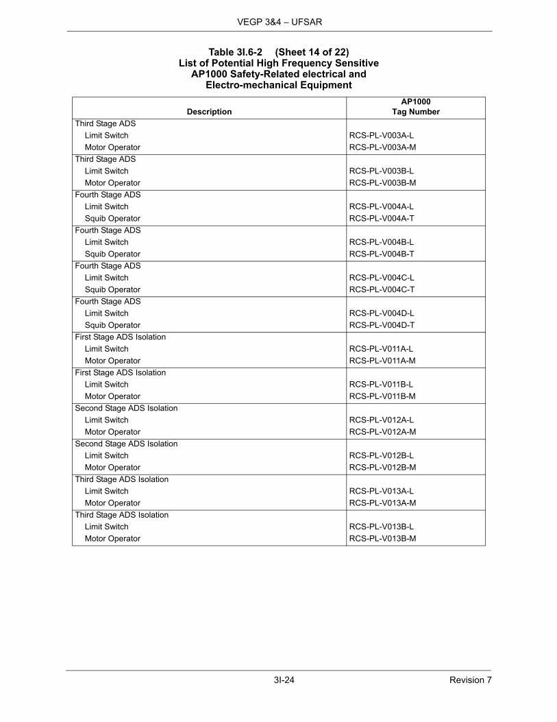
3I-24 Revision 7
VEGP 3&4 – UFSAR
Third Stage ADS
Limit Switch RCS-PL-V003A-L
Motor Operator RCS-PL-V003A-M
Third Stage ADS
Limit Switch RCS-PL-V003B-L
Motor Operator RCS-PL-V003B-M
Fourth Stage ADS
Limit Switch RCS-PL-V004A-L
Squib Operator RCS-PL-V004A-T
Fourth Stage ADS
Limit Switch RCS-PL-V004B-L
Squib Operator RCS-PL-V004B-T
Fourth Stage ADS
Limit Switch RCS-PL-V004C-L
Squib Operator RCS-PL-V004C-T
Fourth Stage ADS
Limit Switch RCS-PL-V004D-L
Squib Operator RCS-PL-V004D-T
First Stage ADS Isolation
Limit Switch RCS-PL-V011A-L
Motor Operator RCS-PL-V011A-M
First Stage ADS Isolation
Limit Switch RCS-PL-V011B-L
Motor Operator RCS-PL-V011B-M
Second Stage ADS Isolation
Limit Switch RCS-PL-V012A-L
Motor Operator RCS-PL-V012A-M
Second Stage ADS Isolation
Limit Switch RCS-PL-V012B-L
Motor Operator RCS-PL-V012B-M
Third Stage ADS Isolation
Limit Switch RCS-PL-V013A-L
Motor Operator RCS-PL-V013A-M
Third Stage ADS Isolation
Limit Switch RCS-PL-V013B-L
Motor Operator RCS-PL-V013B-M
Table 3I.6-2 (Sheet 14 of 22)List of Potential High Frequency Sensitive
AP1000 Safety-Related electrical and Electro-mechanical Equipment
DescriptionAP1000
Tag Number

3I-25 Revision 7
VEGP 3&4 – UFSAR
Reactor Vessel Head Vent
Limit Switch RCS-PL-V150A-L
Solenoid Operator RCS-PV-V150A-S
Voltage Control Box RCS-DJ-01
Reactor Vessel Head Vent
Limit Switch RCS-PL-V150B-L
Solenoid Operator RCS-PL-V150B-S
Voltage Control Box RCS-DJ-02
Reactor Vessel Head Vent
Limit Switch RCS-PL-V150C-L
Solenoid Operator RCS-PL-V150C-S
Voltage Control Box RCS-DJ-03
Reactor Vessel Head Vent
Limit Switch RCS-PL-V150D-L
Solenoid Operator RCS-PL-V150D-S
Voltage Control Box RCS-DJ-04
RCS Inner Suction Isolation
Limit Switch RNS-PL-V001A-L
Motor Operator RNS-PL-V001A-M
RCS Inner Suction Isolation
Limit Switch RNS-PL-V001B-L
Motor Operator RNS-PL-V001B-M
RCS Outer Suction Isolation
Limit Switch RNS-PL-V002A-L
Motor Operator RNS-PL-V002A-M
RCS Outer Suction Isolation
Limit Switch RNS-PL-V002B-L
Motor Operator RNS-PL-V002B-M
RNS Discharge Containment Isolation Valve
Limit Switch RNS-PL-V011-L
Motor Operator RNS-PL-V011-M
RNS Suction Header Containment Isolation
Limit Switch RNS-PL-V022-L
Motor Operator RNS-PL-V022-M
Table 3I.6-2 (Sheet 15 of 22)List of Potential High Frequency Sensitive
AP1000 Safety-Related electrical and Electro-mechanical Equipment
DescriptionAP1000
Tag Number
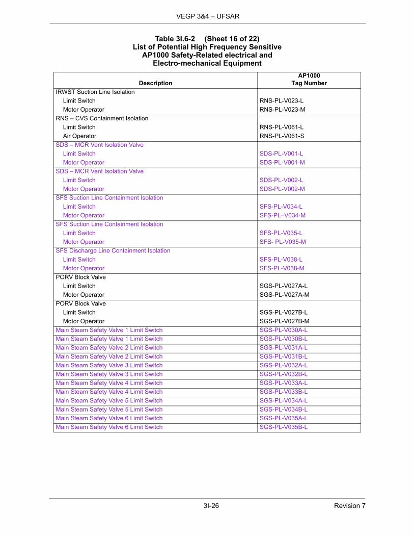
3I-26 Revision 7
VEGP 3&4 – UFSAR
IRWST Suction Line Isolation
Limit Switch RNS-PL-V023-L
Motor Operator RNS-PL-V023-M
RNS – CVS Containment Isolation
Limit Switch RNS-PL-V061-L
Air Operator RNS-PL-V061-S
SDS – MCR Vent Isolation Valve
Limit Switch SDS-PL-V001-L
Motor Operator SDS-PL-V001-M
SDS – MCR Vent Isolation Valve
Limit Switch SDS-PL-V002-L
Motor Operator SDS-PL-V002-M
SFS Suction Line Containment Isolation
Limit Switch SFS-PL-V034-L
Motor Operator SFS-PL–V034-M
SFS Suction Line Containment Isolation
Limit Switch SFS-PL-V035-L
Motor Operator SFS- PL-V035-M
SFS Discharge Line Containment Isolation
Limit Switch SFS-PL-V038-L
Motor Operator SFS-PL-V038-M
PORV Block Valve
Limit Switch SGS-PL-V027A-L
Motor Operator SGS-PL-V027A-M
PORV Block Valve
Limit Switch SGS-PL-V027B-L
Motor Operator SGS-PL-V027B-M
Main Steam Safety Valve 1 Limit Switch SGS-PL-V030A-L
Main Steam Safety Valve 1 Limit Switch SGS-PL-V030B-L
Main Steam Safety Valve 2 Limit Switch SGS-PL-V031A-L
Main Steam Safety Valve 2 Limit Switch SGS-PL-V031B-L
Main Steam Safety Valve 3 Limit Switch SGS-PL-V032A-L
Main Steam Safety Valve 3 Limit Switch SGS-PL-V032B-L
Main Steam Safety Valve 4 Limit Switch SGS-PL-V033A-L
Main Steam Safety Valve 4 Limit Switch SGS-PL-V033B-L
Main Steam Safety Valve 5 Limit Switch SGS-PL-V034A-L
Main Steam Safety Valve 5 Limit Switch SGS-PL-V034B-L
Main Steam Safety Valve 6 Limit Switch SGS-PL-V035A-L
Main Steam Safety Valve 6 Limit Switch SGS-PL-V035B-L
Table 3I.6-2 (Sheet 16 of 22)List of Potential High Frequency Sensitive
AP1000 Safety-Related electrical and Electro-mechanical Equipment
DescriptionAP1000
Tag Number
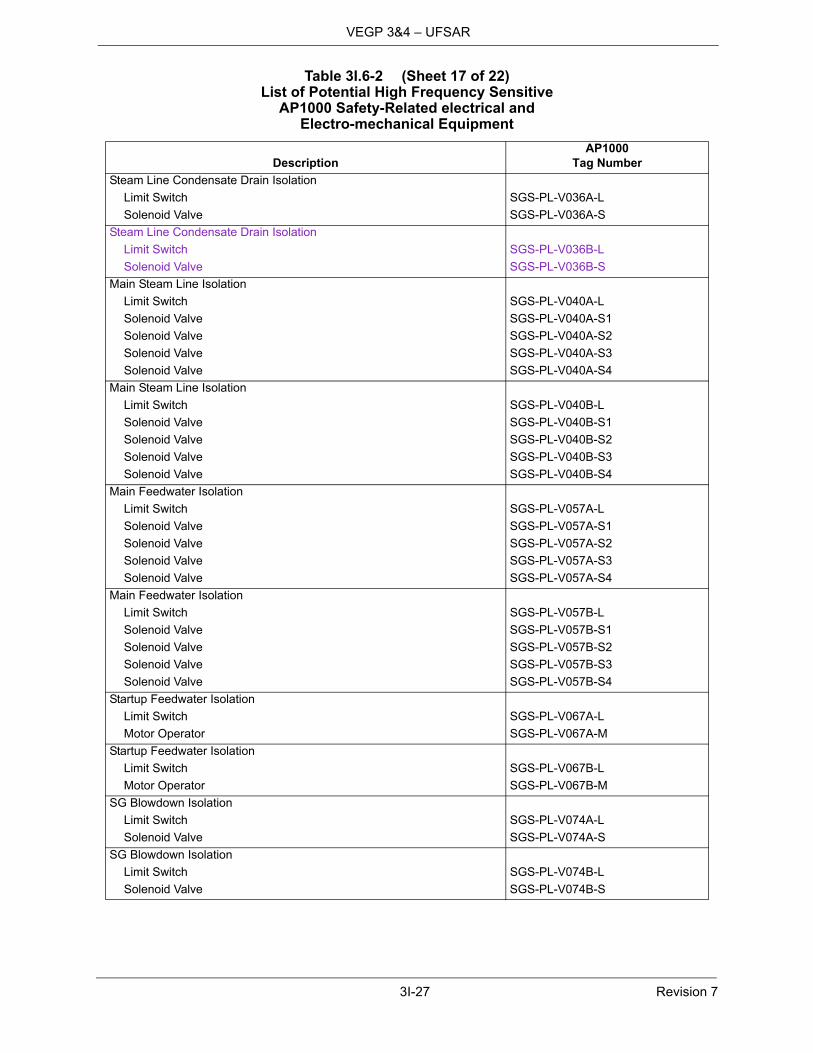
3I-27 Revision 7
VEGP 3&4 – UFSAR
Steam Line Condensate Drain Isolation
Limit Switch SGS-PL-V036A-L
Solenoid Valve SGS-PL-V036A-S
Steam Line Condensate Drain Isolation
Limit Switch SGS-PL-V036B-L
Solenoid Valve SGS-PL-V036B-S
Main Steam Line Isolation
Limit Switch SGS-PL-V040A-L
Solenoid Valve SGS-PL-V040A-S1
Solenoid Valve SGS-PL-V040A-S2
Solenoid Valve SGS-PL-V040A-S3
Solenoid Valve SGS-PL-V040A-S4
Main Steam Line Isolation
Limit Switch SGS-PL-V040B-L
Solenoid Valve SGS-PL-V040B-S1
Solenoid Valve SGS-PL-V040B-S2
Solenoid Valve SGS-PL-V040B-S3
Solenoid Valve SGS-PL-V040B-S4
Main Feedwater Isolation
Limit Switch SGS-PL-V057A-L
Solenoid Valve SGS-PL-V057A-S1
Solenoid Valve SGS-PL-V057A-S2
Solenoid Valve SGS-PL-V057A-S3
Solenoid Valve SGS-PL-V057A-S4
Main Feedwater Isolation
Limit Switch SGS-PL-V057B-L
Solenoid Valve SGS-PL-V057B-S1
Solenoid Valve SGS-PL-V057B-S2
Solenoid Valve SGS-PL-V057B-S3
Solenoid Valve SGS-PL-V057B-S4
Startup Feedwater Isolation
Limit Switch SGS-PL-V067A-L
Motor Operator SGS-PL-V067A-M
Startup Feedwater Isolation
Limit Switch SGS-PL-V067B-L
Motor Operator SGS-PL-V067B-M
SG Blowdown Isolation
Limit Switch SGS-PL-V074A-L
Solenoid Valve SGS-PL-V074A-S
SG Blowdown Isolation
Limit Switch SGS-PL-V074B-L
Solenoid Valve SGS-PL-V074B-S
Table 3I.6-2 (Sheet 17 of 22)List of Potential High Frequency Sensitive
AP1000 Safety-Related electrical and Electro-mechanical Equipment
DescriptionAP1000
Tag Number

3I-28 Revision 7
VEGP 3&4 – UFSAR
SG Series Blowdown Isolation
Limit Switch SGS-PL-V075A-L
Solenoid Valve SGS-PL-V075A-S
SG Series Blowdown Isolation
Limit Switch SGS-PL-V075B-L
Solenoid Valve SGS-PL-V075B-S
Steam Line Condensate Drain Isolation
Level Switch SGS-PL-V086A-L
Solenoid Valve SGS-PL-V086A-S
Steam Line Condensate Drain Isolation
Limit Switch SGS-PL-V086B-L
Solenoid Valve SGS-PL-V086B-S
Power Operated Relief Valve
Limit Switch SGS-PL-V233A-L
Solenoid Valve SGS-PL-V233A-S
Power Operated Relief Valve
Limit Switch SGS-PL-V233B-L
Solenoid Valve SGS-PL-V233B-S
MSIV Bypass Isolation Valve
Limit Switch SGS- PL-V240A-L
Solenoid Valve SGS-PL-V240A-S1
Solenoid Valve SGS-PL-V240A-S2
MSIV Bypass Isolation Valve
Limit Switch SGS-PL-V240B-L
Solenoid Valve SGS-PL-V240B-S1
Solenoid Valve SGS-PL-V240B-S2
Main Feedwater Control Valve
Limit Switch SGS-PL-V250A-L
Solenoid Valve SGS-PL-V250A-S
Main Feedwater Control Valve
Limit Switch SGS-PL-V250B-L
Solenoid Valve SGS-PL-V250B-S
Startup Feedwater Control Valve
Limit Switch SGS-PL-V255A-L
Solenoid Valve SGS-PL-V255A-S
Startup Feedwater Control Valve
Limit Switch SGS-PL-V255B-L
Solenoid Valve SGS-PL-V255B-S
Table 3I.6-2 (Sheet 18 of 22)List of Potential High Frequency Sensitive
AP1000 Safety-Related electrical and Electro-mechanical Equipment
DescriptionAP1000
Tag Number

3I-29 Revision 7
VEGP 3&4 – UFSAR
MCR Isolation Valve
Limit Switch VBS-PL-V186-L
Motor Operator VBS-PL-V186-M
MCR Isolation Valve
Limit Switch VBS-PL-V187-L
Motor Operator VBS-PL-V187-M
MCR Isolation Valve
Limit Switch VBS-PL-V188-L
Motor Operator VBS-PL-V188-M
MCR Isolation Valve
Limit Switch VBS-PL-V189-L
Motor Operator VBS-PL-V189-M
MCR Isolation Valve
Limit Switch VBS-PL-V190-L
Motor Operator VBS-PL-V190-M
MCR Isolation Valve
Limit Switch VBS-PL-V191-L
Motor Operator VBS-PL-V191-M
Air Delivery Isolation Valve A
Limit Switch VES-PL-V005A-L
Solenoid Operator VES-PL-V005A-S
Voltage Control Box VES-DJ-01
Air Delivery Isolation Valve B
Limit Switch VES-PL-V005B-L
Solenoid Operator VES-PL-V005B-S
Voltage Control Box VES-DJ-02
Relief Isolation Valve A
Limit Switch VES-PL-V022A-L
Solenoid Valve VES-PL-V022A-S
Relief Isolation Valve B
Limit Switch VES-PL-V022B-L
Solenoid Valve VES-PL-V022B-S
Containment Purge Inlet Isolation
Limit Switch VFS-PL-V003-L
Solenoid Valve VFS-PL-V003-S1
Containment Purge Inlet Isolation
Limit Switch VFS-PL-V004-L
Solenoid Valve VFS-PL-V004-S1
Table 3I.6-2 (Sheet 19 of 22)List of Potential High Frequency Sensitive
AP1000 Safety-Related electrical and Electro-mechanical Equipment
DescriptionAP1000
Tag Number

3I-30 Revision 7
VEGP 3&4 – UFSAR
Containment Purge Discharge Isolation
Limit Switch VFS-PL-V009-L
Solenoid Valve VFS-PL-V009-S1
Containment Purge Discharge Isolation
Limit Switch VFS-PL-V010-L
Solenoid Valve VFS-PL-V010-S1
Vacuum Relief Containment Isolation Valve A - ORC
Limit Switch VFS-PL-V800A-L
Motor Operator VFS-PL-V800A-M
Vacuum Relief Containment Isolation Valve B - ORC
Limit Switch VFS-PL-V800B-L
Motor Operator VFS-PL-V800B-M
Fan Cooler Supply Isolation
Limit Switch VWS-PL-V058-L
Solenoid Valve VWS-PL-V058-S
Fan Cooler Return Isolation
Limit Switch VWS-PL-V082-L
Solenoid Valve VWS-PL-V082-S
Fan Cooler Return Isolation
Limit Switch VWS-PL-V086-L
Solenoid Valve VWS-PL-V086-S
Sump Containment Isolation IRC
Limit Switch WLS-PL-V055-L
Solenoid Valve WLS-PL-V055-S1
Sump Containment Isolation ORC
Limit Switch WLS-PL-V057-L
Solenoid Valve WLS-PL-V057-S1
RCDT Gas Containment Isolation
Limit Switch WLS-PL-V067-L
Solenoid Valve WLS-PL-V067-S
RCDT Gas Containment Isolation
Limit Switch WLS-PL-V068-L
Solenoid Valve WLS-PL-V068-S
Table 3I.6-2 (Sheet 20 of 22)List of Potential High Frequency Sensitive
AP1000 Safety-Related electrical and Electro-mechanical Equipment
DescriptionAP1000
Tag Number

3I-31 Revision 7
VEGP 3&4 – UFSAR
Nonactive Valves
Hot Leg 1 Sample Isolation
Limit Switch PSS-PL-V001A-L
Solenoid Valve PSS-PL-V001A-S
Voltage Control Box PSS-DJ-01
Hot Leg 2 Sample Isolation
Limit Switch PSS-PL-V001B-L
Solenoid Valve PSS-PL-V001B-S
Voltage Control Box PSS-DJ-02
Core Makeup Tank A CL Inlet Isolation
Limit Switch PXS-PL-V002A-L
Motor Operator PXS-PL-V002A-M
Core Makeup Tank B CL Inlet Isolation
Limit Switch PXS-PL-V002B-L
Motor Operator PXS-PL-V002B-M
Accumulator A N2 Vent Isolation
Limit Switch PXS-PL-V021A-L
Solenoid Valve PXS-PL-V021A-S
Accumulator B N2 Vent Isolation
Limit Switch PXS-PL-V021B-L
Solenoid Valve PXS-PL-V021B-S
Accumulator A Discharge Isolation
Limit Switch PXS-PL-V027A-L
Motor Operator PXS-PL-V027A-M
Accumulator B Discharge Isolation
Limit Switch PXS-PL-V027B-L
Motor Operator PXS-PL-V027B-M
PRHR HX Inlet Isolation
Limit Switch PXS-PL-V101-L
Motor Operator PXS-PL-V101-M
Recirc Sump A Isolation
Limit Switch PXS-PL-V117A-L
Motor Operator PXS-PL-V117A-M
Table 3I.6-2 (Sheet 21 of 22)List of Potential High Frequency Sensitive
AP1000 Safety-Related electrical and Electro-mechanical Equipment
DescriptionAP1000
Tag Number
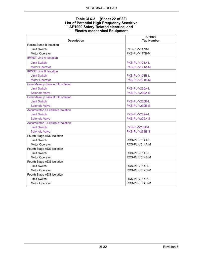
3I-32 Revision 7
VEGP 3&4 – UFSAR
Recirc Sump B Isolation
Limit Switch PXS-PL-V117B-L
Motor Operator PXS-PL-V117B-M
IRWST Line A Isolation
Limit Switch PXS-PL-V121A-L
Motor Operator PXS-PL-V121A-M
IRWST Line B Isolation
Limit Switch PXS-PL-V121B-L
Motor Operator PXS-PL-V121B-M
Core Makeup Tank A Fill Isolation
Limit Switch PXS-PL-V230A-L
Solenoid Valve PXS-PL-V230A-S
Core Makeup Tank B Fill Isolation
Limit Switch PXS-PL-V230B-L
Solenoid Valve PXS-PL-V230B-S
Accumulator A Fill/Drain Isolation
Limit Switch PXS-PL-V232A-L
Solenoid Valve PXS-PL-V232A-S
Accumulator B Fill/Drain Isolation
Limit Switch PXS-PL-V232B-L
Solenoid Valve PXS-PL-V232B-S
Fourth Stage ADS Isolation
Limit Switch RCS-PL-V014A-L
Motor Operator RCS-PL-V014A-M
Fourth Stage ADS Isolation
Limit Switch RCS-PL-V014B-L
Motor Operator RCS-PL-V014B-M
Fourth Stage ADS Isolation
Limit Switch RCS-PL-V014C-L
Motor Operator RCS-PL-V014C-M
Fourth Stage ADS Isolation
Limit Switch RCS-PL-V014D-L
Motor Operator RCS-PL-V014D-M
Table 3I.6-2 (Sheet 22 of 22)List of Potential High Frequency Sensitive
AP1000 Safety-Related electrical and Electro-mechanical Equipment
DescriptionAP1000
Tag Number

3I-33 Revision 7
VEGP 3&4 – UFSAR
Table 3I.6-3 (Sheet 1 of 23)List Of AP1000 Safety-Related Electrical
and Mechanical Equipment Not High Frequency Sensitive
DescriptionAP1000
Tag Number Comment
Resistance Temperature Detectors
PRHR HX Outlet Temperature RCS-JE-TE161 1
RCS Cold Leg 1A Narrow Range Temperature RCS-JE-TE121A 1
RCS Cold Leg 1A Narrow Range Temperature RCS-JE-TE121D 1
RCS Cold Leg 1B Narrow Range Temperature RCS-JE-TE121B 1
RCS Cold Leg 1B Narrow Range Temperature RCS-JE-TE121C 1
RCS Cold Leg 2A Narrow Range Temperature RCS-JE-TE122B 1
RCS Cold Leg 2A Narrow Range Temperature RCS-JE-TE122C 1
RCS Cold Leg 2B Narrow Range Temperature RCS-JE-TE122A 1
RCS Cold Leg 2B Narrow Range Temperature RCS-JE-TE122D 1
RCS Hot Leg 1 Narrow Range Temperature RCS-JE-TE131A 1
RCS Hot Leg 1 Narrow Range Temperature RCS-JE-TE131C 1
RCS Hot Leg 1 Narrow Range Temperature RCS-JE-TE132A 1
RCS Hot Leg 1 Narrow Range Temperature RCS-JE-TE132C 1
RCS Hot Leg 1 Narrow Range Temperature RCS-JE-TE133C 1
RCS Hot Leg 1 Narrow Range Temperature RCS-JE-TE133A 1
RCS Hot Leg 2 Narrow Range Temperature RCS-JE-TE131B 1
RCS Hot Leg 2 Narrow Range Temperature RCS-JE-TE131D 1
RCS Hot Leg 2 Narrow Range Temperature RCS-JE-TE132B 1
RCS Hot Leg 2 Narrow Range Temperature RCS-JE-TE132D 1
RCS Hot Leg 2 Narrow Range Temperature RCS-JE-TE133B 1
RCS Hot Leg 2 Narrow Range Temperature RCS-JE-TE133D 1
RCS Cold Leg 1A Dual Range Temperature RCS-JE-TE125A 1
RCS Cold Leg 1B Dual Range Temperature RCS-JE-TE125C 1
RCS Cold Leg 2A Dual Range Temperature RCS-JE-TE125B 1
RCS Cold Leg 2B Dual Range Temperature RCS-JE-TE125D 1
RCS Hot Leg 1 Wide Range Temperature RCS-JE-TE135A 1
RCS Hot Leg 2 Wide Range Temperature RCS-JE-TE135B 1
PZR Reference Leg Level Temperature RCS-JE-TE193A 1
PZR Reference Leg Level Temperature RCS-JE-TE193B 1
PZR Reference Leg Level Temperature RCS-JE-TE193C 1
PZR Reference Leg Level Temperature RCS-JE-TE193D 1

3I-34 Revision 7
VEGP 3&4 – UFSAR
RCP 1A Bearing Water Temperature RCS-JE-TE211A 1
RCP 1A Bearing Water Temperature RCS-JE-TE211B 1
RCP 1A Bearing Water Temperature RCS-JE-TE211C 1
RCP 1A Bearing Water Temperature RCS-JE-TE211D 1
RCP 1B Bearing Water Temperature RCS-JE-TE212A 1
RCP 1B Bearing Water Temperature RCS-JE-TE212B 1
RCP 1B Bearing Water Temperature RCS-JE-TE212C 1
RCP 1B Bearing Water Temperature RCS-JE-TE212D 1
RCP 2A Bearing Water Temperature RCS-JE-TE213A 1
RCP 2A Bearing Water Temperature RCS-JE-TE213B 1
RCP 2A Bearing Water Temperature RCS-JE-TE213C 1
RCP 2A Bearing Water Temperature RCS-JE-TE213D 1
RCP 2B Bearing Water Temperature RCS-JE-TE214A 1
RCP 2B Bearing Water Temperature RCS-JE-TE214B 1
RCP 2B Bearing Water Temperature RCS-JE-TE214C 1
RCP 2B Bearing Water Temperature RCS-JE-TE214D 1
Thermocouples 1
Incore Thermocouples IIS-JE-TE001-TE042 1
Penetrations
Penetrations (Mechanical) 1
Penetrations (Electrical) 1
Active Valves
Containment Isolation – Air Out CAS-PL-V014 2
Containment Isolation – Air In CAS-PL-V015 2
Containment Isolation – Inlet CCS-PL-V200 2
Service Air Supply Inside Containment Isolation CAS-PL-V205 2
Containment Isolation – Inlet CCS-PL-V201 2
Containment Isolation – Outlet CCS-PL-V207 2
Containment Isolation – Outlet CCS-PL-V208 2
CCS Containment Isolation Relief CCS-PL-V220 2
CCS IRC Relief Valve CCS-PL-V270 2
CCS IRC Relief Valve CCS-PL-V271 2
RCS Purification Stop Valve CVS-PL-V001 2
RCS Purification Stop Valve CVS-PL-V002 2
RCS Letdown Stop Valve CVS-PL-V003 2
Demineralizer Flush Line Relief Valve CVS-PL-V042 2
Table 3I.6-3 (Sheet 2 of 23)List Of AP1000 Safety-Related Electrical
and Mechanical Equipment Not High Frequency Sensitive
DescriptionAP1000
Tag Number Comment

3I-35 Revision 7
VEGP 3&4 – UFSAR
WLS Letdown IRC Isolation CVS-PL-V045 2
Letdown Flow ORC Isolation CVS-PL-V047 2
Letdown Line Containment Isolation Thermal Relief CVS-PL-V058 2
CVS Makeup Line Bypass Check Valve CVS-PL-V067 2
RCS Purification Check Valve CVS-PL-V080 2
RCS Purification Stop Valve CVS-PL-V081 2
RCS Purification Check Valve CVS-PL-V082 2
Auxiliary PZR Spray Isolation CVS-PL-V084 2
Auxiliary PZR Spray Isolation CVS-PL-V085 2
Makeup Line Containment Isolation CVS-PL-V090 2
Makeup Line Containment Isolation CVS-PL-V091 2
Zinc Addition Containment Isolation CVS-PL-V092 2
Zinc Addition Containment Isolation CVS-PL-V094 2
Zinc Injection Containment Isolation Thermal Overpressurization Relief Valve
CVS-PL-V098 2
Makeup Containment Isolation CVS-PL-V100 2
Demineralizer Water System Isolation CVS-PL-V136A 2
Demineralized Water System Isolation CVS-PL-V136B 2
Hydrogen Injection Containment Isolation Check Valve CVS-PL-V217 2
Hydrogen Injection Containment Isolation CVS-PL-V219 2
DWS Containment Penetration Thermal Relief Valve DWS-PL-V241 2
Demin Water Supply Containment Isolation – Inside DWS-PL-V245 2
Fuel Transfer Tube Gate Valve FHS-PL-V001 2
Fire Water Containment Supply Isolation – Inside FPS-PL-V052 2
FPS Containment Penetration Thermal Relief Valve FPS-PL-V702 2
PCCWST Isolation Valve PCS-PL-V001A 2
PCCWST Isolation Valve PCS-PL-V001B 2
PCCWST Isolation Valve PCS-PL-V001C 2
PCCWST Isolation Valve PCS-PL-V002A 2
PCCWST Isolation Valve PCS-PL-V002B 2
PCCWST Isolation Valve PCS-PL-V002C 2
PCCWST Fire Protection Isolation PCS-PL-V005 2
PCCWST Emergency Spent Fuel Pool Makeup Isolation PCS-PL-V009 2
Water Bucket Makeup Line Drain Valve PCS-PL-V015 2
Water Bucket Makeup Line Isolation Valve PCS-PL-V020 2
PCS Recirculation Isolation PCS-PL-V023 2
PCCWST Long-Term Makeup Check Valve PCS-PL-V039 2
PCCWST Long Term Makeup Isolation Drain Valve PCS-PL-V042 2
PCCWST Long Term Makeup Isolation Valve PCS-PL-V044 2
Emergency Makeup to the Spent Fuel Pool Isolation Valve PCS-PL-V045 2
Table 3I.6-3 (Sheet 3 of 23)List Of AP1000 Safety-Related Electrical
and Mechanical Equipment Not High Frequency Sensitive
DescriptionAP1000
Tag Number Comment

3I-36 Revision 7
VEGP 3&4 – UFSAR
PCCWST Recirculation Return Isolation Valve PCS-PL-V046 2
Emergency Makeup to the Spent Fuel Pool Drain Isolation Valve PCS-PL-V049 2
Spent Fuel Pool Long Term Makeup Isolation Valve PCS-PL-V050 2
Spent Fuel Pool Emergency Makeup Lower Isolation Valve PCS-PL-V051 2
Shutoff Valve for Leakage Sensor PCS-PL-V060A 2
Shutoff Valve for Leakage Sensor PCS-PL-V060B 2
Containment Isolation – Air Sample Line PSS-PL-V008 2
Containment Isolation – Liquid Sample Line PSS-PL-V010A 2
Containment Isolation – Liquid Sample Line PSS-PL-V010B 2
Containment Isolation – Liquid Sample Line PSS-PL-V011A 2
Containment Isolation – Liquid Sample Line PSS-PL-V011B 2
Containment Isolation – Sample Return Line PSS-PL-V023 2
Containment Isolation Sample Return PSS-PL-V024 2
Containment Isolation – Air Sample Line PSS-PL-V046 2
PWS MCR Isolation Valve PWS-PL-V418 2
PWS MCR Isolation Valve PWS-PL-V420 2
PWS MCR Vacuum Relief PWS-PL-V498 2
Core Makeup Tank A Discharge Isolation PXS-PL-V014A 2
Core Makeup Tank B Discharge Isolation PXS-PL-V014B 2
Core Makeup Tank A Discharge Isolation PXS-PL-V015A 2
Core Makeup Tank B Discharge Isolation PXS-PL-V015B 2
Core Makeup Tank A Discharge PXS-PL-V016A 2
Core Makeup Tank B Discharge PXS-PL-V016B 2
Core Makeup Tank A Discharge PXS-PL-V017A 2
Core Makeup Tank B Discharge PXS-PL-V017B 2
Accumulator A Pressure Relief PXS-PL-V022A 2
Accumulator B Pressure Relief PXS-PL-V022B 2
Accumulator A Discharge PXS-PL-V028A 2
Accumulator B Discharge PXS-PL-V028B 2
Accumulator A Discharge PXS-PL-V029A 2
Accumulator B Discharge PXS-PL-V029B 2
Nitrogen Supply Outside Containment Isolation PXS-PL-V042 2
Nitrogen Supply Containment Isolation IRC Check Valve PXS-PL-V043 2
PRHR HX Discharge Isolation PXS-PL-V108A 2
PRHR HX Discharge Isolation PXS-PL-V108B 2
Table 3I.6-3 (Sheet 4 of 23)List Of AP1000 Safety-Related Electrical
and Mechanical Equipment Not High Frequency Sensitive
DescriptionAP1000
Tag Number Comment

3I-37 Revision 7
VEGP 3&4 – UFSAR
Recirc Sump A Isolation PXS-PL-V118A 2
Recirc Sump B Isolation PXS-PL-V118B 2
Recirc Sump A Isolation PXS-PL-V119A 2
Recirc Sump B Isolation PXS-PL-V119B 2
Recirc Sump A Isolation PXS-PL-V120A 2
Recirc Sump B Isolation PXS- PL-V120B 2
IRWST Injection A PXS-PL-V122A 2
IRWST Injection B PXS-PL-V122B 2
IRWST Injection A PXS-PL-V123A 2
IRWST Injection B PXS-PL-V123B 2
IRWST Injection A PXS-PL-V124A 2
IRWST Injection B PXS-PL-V124B 2
IRWST Injection A PXS-PL-V125A 2
IRWST Injection B PXS-PL-V125B 2
IRWST Gutter Drain Isolation A PXS-PL-V130A 2
IRWST Gutter Drain Isolation B PXS-PL-V130B 2
First Stage ADS RCS-PL-V001A 2
First Stage ADS RCS-PL-V001B 2
Second Stage ADS RCS-PL-V002A 2
Second Stage ADS RCS-PL-V002B 2
Third Stage ADS RCS-PL-V003A 2
Third Stage ADS RCS-PL-V003B 2
Fourth Stage ADS RCS-PL-V004A 2
Fourth Stage ADS RCS-PL-V004B 2
Fourth Stage ADS RCS-PL-V004C 2
Fourth Stage ADS RCS-PL-V004D 2
PZR Safety Valve RCS-PL-V005A 2
PZR Safety Valve RCS-PL-V005B 2
ADS Discharge Header A Relief RCS-PL-V010A 2
ADS Discharge Header B Relief RCS-PL-V010B 2
First Stage ADS Isolation RCS-PL-V011A 2
First Stage ADS Isolation RCS-PL-V011B 2
Second Stage ADS Isolation RCS-PL-V012A 2
Second Stage ADS Isolation RCS-PL-V012B 2
Third Stage ADS Isolation RCS-PL-V013A 2
Third Stage ADS Isolation RCS-PL-V013B 2
Table 3I.6-3 (Sheet 5 of 23)List Of AP1000 Safety-Related Electrical
and Mechanical Equipment Not High Frequency Sensitive
DescriptionAP1000
Tag Number Comment

3I-38 Revision 7
VEGP 3&4 – UFSAR
Reactor Vessel Head Vent RCS-PL-V150A 2
Reactor Vessel Head Vent RCS-PL-V150B 2
Reactor Vessel Head Vent RCS-PL-V150C 2
Reactor Vessel Head Vent RCS-PL-V150D 2
RCS Inner Suction Isolation RNS-PL-V001A 2
RCS Inner Suction Isolation RNS-PL-V001B 2
RCS Outer Suction Isolation RNS-PL-V002A 2
RCS Outer Suction Isolation RNS-PL-V002B 2
RCS Thermal Relief RNS-PL-V003A 2
RCS Thermal Relief RNS-PL-V003B 2
RNS Discharge Containment Isolation Valve RNS-PL-V011 2
RNS Discharge Containment Isolation Valve Test Connection RNS-PL-V012 2
RNS Discharge Containment Isolation RNS-PL-V013 2
RNS Discharge RCS Pressure Boundary RNS-PL-V015A 2
RNS Discharge RCS Pressure Boundary RNS-PL-V015B 2
RNS Discharge RCS Pressure Boundary RNS-PL-V017A 2
RNS Discharge RCS Pressure Boundary RNS-PL-V017B 2
RNS Hot Leg Suction Relief RNS-PL-V020 2
RNS Hot Leg Suction Relief RNS-PL-V021 2
RNS Suction Header Containment Isolation RNS-PL-V022 2
IRWST Suction Line Isolation RNS-PL-V023 2
RNS Pump Discharge Relief RNS-PL-V045 2
RNS – CVS Containment Isolation RNS-PL-V061 2
SDS MCR Vent Isolation Valve SDS-PL-V001 2
SDS MCR Vent Isolation Valve SDS-PL-V002 2
SFS Suction Line Containment Isolation SFS-PL-V034 2
SFS Suction Line Containment Isolation SFS-PL-V035 2
SFS Discharge Containment Isolation SFS-PL-V037 2
SFS Discharge Line Containment Isolation SFS-PL-V038 2
SFS Cask Loading Pit to SFS Pump SFS-PL-V042 2
SFS Pump to Cask Loading Pit SFS-PL-V045 2
Cask Loading Pit to WLS SFS-PL-V049 2
Spent Fuel Pool to Cask Washdown Pit Isolation SFS-PL-V066 2
SFS Containment Isolation Relief SFS-PL-V067 2
Cask Washdown Pit Drain Isolation SFS-PL-V068 2
Refueling Cavity to SG Compartment SFS-PL-V071 2
Refueling Cavity to SG Compartment SFS-PL-V072 2
Refueling Cavity Drain Line Test Connection SFS-PL-V117 2
PORV Block Valve SGS-PL-V027A 2
PORV Block Valve SGS-PL-V027B 2
Table 3I.6-3 (Sheet 6 of 23)List Of AP1000 Safety-Related Electrical
and Mechanical Equipment Not High Frequency Sensitive
DescriptionAP1000
Tag Number Comment
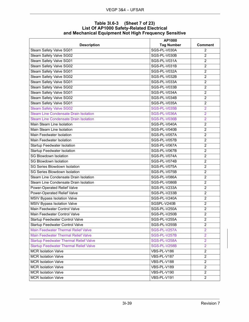
3I-39 Revision 7
VEGP 3&4 – UFSAR
Steam Safety Valve SG01 SGS-PL-V030A 2
Steam Safety Valve SG02 SGS-PL-V030B 2
Steam Safety Valve SG01 SGS-PL-V031A 2
Steam Safety Valve SG02 SGS-PL-V031B 2
Steam Safety Valve SG01 SGS-PL-V032A 2
Steam Safety Valve SG02 SGS-PL-V032B 2
Steam Safety Valve SG01 SGS-PL-V033A 2
Steam Safety Valve SG02 SGS-PL-V033B 2
Steam Safety Valve SG01 SGS-PL-V034A 2
Steam Safety Valve SG02 SGS-PL-V034B 2
Steam Safety Valve SG01 SGS-PL-V035A 2
Steam Safety Valve SG02 SGS-PL-V035B 2
Steam Line Condensate Drain Isolation SGS-PL-V036A 2
Steam Line Condensate Drain Isolation SGS-PL-V036B 2
Main Steam Line Isolation SGS-PL-V040A 2
Main Steam Line Isolation SGS-PL-V040B 2
Main Feedwater Isolation SGS-PL-V057A 2
Main Feedwater Isolation SGS-PL-V057B 2
Startup Feedwater Isolation SGS-PL-V067A 2
Startup Feedwater Isolation SGS-PL-V067B 2
SG Blowdown Isolation SGS-PL-V074A 2
SG Blowdown Isolation SGS-PL-V074B 2
SG Series Blowdown Isolation SGS-PL-V075A 2
SG Series Blowdown Isolation SGS-PL-V075B 2
Steam Line Condensate Drain Isolation SGS-PL-V086A 2
Steam Line Condensate Drain Isolation SGS-PL-V086B 2
Power-Operated Relief Valve SGS-PL-V233A 2
Power-Operated Relief Valve SGS-PL-V233B 2
MSIV Bypass Isolation Valve SGS-PL-V240A 2
MSIV Bypass Isolation Valve SGSPL-V240B 2
Main Feedwater Control Valve SGS-PL-V250A 2
Main Feedwater Control Valve SGS-PL-V250B 2
Startup Feedwater Control Valve SGS-PL-V255A 2
Startup Feedwater Control Valve SGS-PL-V255B 2
Main Feedwater Thermal Relief Valve SGS-PL-V257A 2
Main Feedwater Thermal Relief Valve SGS-PL-V257B 2
Startup Feedwater Thermal Relief Valve SGS-PL-V258A 2
Startup Feedwater Thermal Relief Valve SGS-PL-V258B 2
MCR Isolation Valve VBS-PL-V186 2
MCR Isolation Valve VBS-PL-V187 2
MCR Isolation Valve VBS-PL-V188 2
MCR Isolation Valve VBS-PL-V189 2
MCR Isolation Valve VBS-PL-V190 2
MCR Isolation Valve VBS-PL-V191 2
Table 3I.6-3 (Sheet 7 of 23)List Of AP1000 Safety-Related Electrical
and Mechanical Equipment Not High Frequency Sensitive
DescriptionAP1000
Tag Number Comment
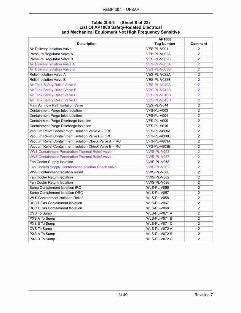
3I-40 Revision 7
VEGP 3&4 – UFSAR
Air Delivery Isolation Valve VES-PL-V001 2
Pressure Regulator Valve A VES-PL-V002A 2
Pressure Regulator Valve B VES-PL-V002B 2
Air Delivery Isolation Valve A VES-PL-V005A 2
Air Delivery Isolation Valve B VES-PL-V005B 2
Relief Isolation Valve A VES-PL-V022A 2
Relief Isolation Valve B VES-PL-V022B 2
Air Tank Safety Relief Valve A VES-PL-V040A 2
Air Tank Safety Relief Valve B VES-PL-V040B 2
Air Tank Safety Relief Valve C VES-PL-V040C 2
Air Tank Safety Relief Valve D VES-PL-V040D 2
Main Air Flow Path Isolation Valve VES-PL-V044 2
Containment Purge Inlet Isolation VFS-PL-V003 2
Containment Purge Inlet Isolation VFS-PL-V004 2
Containment Purge Discharge Isolation VFS-PL-V009 2
Containment Purge Discharge Isolation VFS-PL-V010 2
Vacuum Relief Containment Isolation Valve A - ORC VFS-PL-V800A 2
Vacuum Relief Containment Isolation Valve B - ORC VFS-PL-V800B 2
Vacuum Relief Containment Isolation Check Valve A - IRC VFS-PL-V803A 2
Vacuum Relief Containment Isolation Check Valve B - IRC VFS-PL-V803B 2
VWS Containment Penetration Thermal Relief Valve VWS-PL-V053 2
VWS Containment Penetration Thermal Relief Valve VWS-PL-V057 2
Fan Cooler Supply Isolation VWS-PL-V058 2
Fan Coolers Supply Containment Isolation Check Valve VWS-PL-V062 2
VWS Containment Isolation Relief VWS-PL-V080 2
Fan Cooler Return Isolation VWS-PL-V082 2
Fan Cooler Return Isolation VWS-PL-V086 2
Sump Containment Isolation IRC WLS-PL-V055 2
Sump Containment Isolation ORC WLS-PL-V057 2
WLS Containment Isolation Relief WLS-PL-V058 2
RCDT Gas Containment Isolation WLS-PL-V067 2
RCDT Gas Containment Isolation WLS-PL-V068 2
CVS To Sump WLS-PL-V071 A 2
PXS A To Sump WLS-PL-V071 B 2
PXS B To Sump WLS-PL-V071 C 2
CVS To Sump WLS-PL-V072 A 2
PXS A To Sump WLS-PL-V072 B 2
PXS B To Sump WLS-PL-V072 C 2
Table 3I.6-3 (Sheet 8 of 23)List Of AP1000 Safety-Related Electrical
and Mechanical Equipment Not High Frequency Sensitive
DescriptionAP1000
Tag Number Comment

3I-41 Revision 7
VEGP 3&4 – UFSAR
Miscellaneous
Nonactive Valves
Containment Penetration Test Connection Isolation CAS-PL-V027 2
Service Air Supply Outside Containment Isolation CAS-PL-V204 2
Containment Penetration Test Connection Isolation CAS-PL-V219 2
Containment Isolation Valve Test Connection – Outlet Line CCS-PL-V209 2
CCS Supply Containment Isolation – IRC CCS-PL-V214 2
CCS Supply Containment Isolation Valve Test Connection – IRC CCS-PL-V215 2
Containment Leak Test Outlet Line – IRC CCS-PL-V216 2
Containment Isolation Valve V207 Body Test Connection Valve CCS-PL-V217 2
Containment Isolation Valve Test Connection – Inlet Line CCS-PL-V257 2
Resin Flush IRC Isolation CVS-PL-V040 2
Resin Flush ORC Isolation CVS-PL-V041 2
Letdown PZR Instrument Root CVS-PL-V046 2
Zinc Addition – IRC Shutoff CVS-PL-V065 2
Zinc Add Cont Isolation Test Connection CVS-PL-V095 2
Zinc Addition Containment Isolation Test Connection CVS-PL-V096 2
Hydrogen Injection Containment Isolation Test Connection Valve CVS-PL-V218 2
Demin Water Supply Containment Isolation – Outside DWS-PL-V244 2
Containment Penetration Test Connection Isolation DWS-PL-V248 2
Fire Water Containment Supply Isolation FPS-PL-V050 2
Fire Water Containment Test Connection Isolation FPS-PL-V051 2
Flow Transmitter FT001 Root Valve PCS-PL-V010A 2
Flow Transmitter FT001 Root Valve PCS-PL-V010B 2
Flow Transmitter FT002 Root Valve PCS-PL-V011A 2
Flow Transmitter FT002 Root Valve PCS-PL-V011B 2
Flow Transmitter FT003 Root Valve PCS-PL-V012A 2
Flow Transmitter FT003 Root Valve PCS-PL-V012B 2
Flow Transmitter FT004 Root Valve PCS-PL-V013A 2
Flow Transmitter FT004 Root Valve PCS-PL-V013B 2
PCCWST Drain Isolation Valve PCS-PL-V016 2
Makeup to Distribution Bucket Isolation Valve PCS-PL-V026 2
PCCWST Isolation Valve Leakage Detection Drain PCS-PL-V029 2
PCCWST Isolation Valve Leakage Detection Crossconn PCS-PL-V030 2
PCCWST Level Instrument Root Valve PCS-PL-V031A 2
PCCWST Level Instrument Root Valve PCS-PL-V031B 2
Recirculation Pump Suction from Long Term Makeup Isolation Valve PCS-PL-V033 2
Spent Fuel Pool Emergency Makeup Isolation PCS-PL-V052 2
Recirculation Header Discharge to SFS Pool Vent Isolation Valve PCS-PL-V303 2
Recirculation Header Discharge to SFS Pool Drain Isolation Valve PCS-PL-V304 2
PCCWST Recirculation Return Drain Isolation Valve PCS-PL-V305 2
Table 3I.6-3 (Sheet 9 of 23)List Of AP1000 Safety-Related Electrical
and Mechanical Equipment Not High Frequency Sensitive
DescriptionAP1000
Tag Number Comment

3I-42 Revision 7
VEGP 3&4 – UFSAR
Hot Leg 1 Sample Isolation PSS-PL-V001A 2
Hot Leg 2 Sample Isolation PSS-PL-V001B 2
Pressurizer Sample Isolation PSS-PL-V003 2
PXS Accumulator Sample Isolation PSS-PL-V004A 2
PXS Accumulator Sample Isolation PSS-PL-V004B 2
PXS CMT A Sample Isolation PSS-PL-V005A 2
PXS CMT B Sample Isolation PSS-PL-V005B 2
PXS CMT A Sample Isolation PSS-PL-V005C 2
PXS CMT B Sample Isolation PSS-PL-V005D 2
Liquid Sample Isolation Valve PSS-PL-V012A 2
Liquid Sample Check Valve PSS-PL-V012B 2
RCS Pressurizer Sample Isolation Valve PSS-PL-V013 2
RCS Hot Leg 1 Sample Isolation Valve PSS-PL-V014A 2
RCS Hot Leg 2 Sample Isolation Valve PSS-PL-V014B 2
PXS Accumulator Sample Isolation Valve PSS-PL-V015A 2
PXS Accumulator Sample Isolation Valve PSS-PL-V015B 2
PXS CMT A Sample Isolation Valve PSS-PL-V016A 2
PXS CMT B Sample Isolation Valve PSS-PL-V016B 2
PXS CMT A Sample Isolation Valve PSS-PL-V016C 2
PXS CMT B Sample Isolation Valve PSS-PL-V016D 2
Containment Testing Boundary Isolation Valve PSS-PL-V076A 2
Containment Testing Boundary Isolation Valve PSS-PL-V076B 2
Containment Isolation Test Connection Isolation Valve PSS-PL-V082 2
Containment Isolation Test Connection Isolation Valve PSS-PL-V083 2
Containment Isolation Test Connection Isolation Valve PSS-PL-V085 2
Containment Isolation Test Connection Isolation Valve PSS-PL-V086 2
Core Makeup Tank A CL Inlet Isolation PXS-PL-V002A 2
Core Makeup Tank B CL Inlet Isolation PXS-PL-V002B 2
Core Makeup Tank A Upper Sample PXS-PL-V010A 2
Core Makeup Tank B Upper Sample PXS-PL-V010B 2
Core Makeup Tank A Lower Sample PXS-PL-V011A 2
Core Makeup Tank B Lower Sample PXS-PL-V011B 2
Core Makeup Tank A Drain PXS-PL-V012A 2
Core Makeup Tank B Drain PXS-PL-V012B 2
Core Makeup Tank Discharge Manual Isolation PXS-PL-V013A 2
Core Makeup Tank B Discharge Manual Isolation PXS-PL-V013B 2
RNS to CMT Injection Line A Drain PXS-PL-V019A 2
RNS to CMT Injection Line B Drain PXS-PL-V019B 2
IRWST Injection Line A Drain PXS-PL-V020A 2
IRWST Injection Line B Drain PXS-PL-V020B 2
Table 3I.6-3 (Sheet 10 of 23)List Of AP1000 Safety-Related Electrical
and Mechanical Equipment Not High Frequency Sensitive
DescriptionAP1000
Tag Number Comment

3I-43 Revision 7
VEGP 3&4 – UFSAR
Accumulator A N2 Vent PXS-PL-V021A 2
Accumulator B N2 Vent PXS-PL-V021B 2
Accumulator A PZR Transmitter Isolation PXS-PL-V023A 2
Accumulator B PZR Transmitter Isolation PXS-PL-V023B 2
Accumulator A PZR Transmitter Isolation PXS-PL-V024A 2
Accumulator B PZR Transmitter Isolation PXS-PL-V024B 2
Accumulator A Sample PXS-PL-V025A 2
Accumulator B Sample PXS-PL-V025B 2
Accumulator A Drain PXS-PL-V026A 2
Accumulator B Drain PXS-PL-V026B 2
Accumulator A Discharge Isolation PXS-PL-V027A 2
Accumulator B Discharge Isolation PXS-PL-V027B 2
Core Makeup Tank A Highpoint Vent PXS-PL-V030A 2
Core Makeup Tank B Highpoint Vent PXS-PL-V030B 2
Core Makeup Tank A Highpoint Vent PXS-PL-V031A 2
Core Makeup Tank B Highpoint Vent PXS-PL-V031B 2
Accumulator A Check Valve Drain PXS-PL-V033A 2
Accumulator B Check Valve Drain PXS-PL-V033B 2
Accumulator N2 Containment Penetration Test Connection PXS-PL-V052 2
CMT A Wide Level Upper Root PXS-PL-V080A 2
CMT B Wide Level Upper Root PXS-PL-V080B 2
CMT A Wide Level Lower Root PXS-PL-V081A 2
CMT B Wide Level Lower Root PXS-PL-V081B 2
CMT A Upper Level A Isolation 1 PXS-PL-V082A 2
CMT B Upper Level A Isolation 1 PXS-PL-V082B 2
CMT A Upper Level A Isolation 2 PXS-PL-V083A 2
CMT B Upper Level A Isolation 2 PXS-PL-V083B 2
CMT A Upper Level A Vent PXS-PL-V084A 2
CMT B Upper Level A Vent PXS-PL-V084B 2
CMT A Upper Level A Drain PXS-PL-V085A 2
CMT B Upper Level A Drain PXS-PL-V085B 2
CMT A Upper Level B Isolation 1 PXS-PL-V086A 2
CMT B Upper Level B Isolation 1 PXS-PL-V086B 2
CMT A Upper Level B Isolation 2 PXS-PL-V087A 2
CMT B Upper Level B Isolation 2 PXS-PL-V087B 2
CMT A Upper Level B Vent PXS-PL-V088A 2
CMT B Upper Level B Vent PXS-PL-V088B 2
CMT A Upper Level B Drain PXS-PL-V089A 2
CMT B Upper Level B Drain PXS-PL-V089B 2
Table 3I.6-3 (Sheet 11 of 23)List Of AP1000 Safety-Related Electrical
and Mechanical Equipment Not High Frequency Sensitive
DescriptionAP1000
Tag Number Comment

3I-44 Revision 7
VEGP 3&4 – UFSAR
CMT A Lower Level A Isolation 1 PXS-PL-V092A 2
CMT B Lower Level A Isolation 1 PXS-PL-V092B 2
CMT A Lower Level A Isolation 2 PXS-PL-V093A 2
CMT B Lower Level A Isolation 2 PXS-PL-V093B 2
CMT A Lower Level A Vent PXS-PL-V094A 2
CMT B Lower Level A Vent PXS-PL-V094B 2
CMT A Lower Level A Drain PXS-PL-V095A 2
CMT B Lower Level A Drain PXS-PL-V095B 2
CMT A Lower Level B Isolation 1 PXS-PL-V096A 2
CMT B Lower Level B Isolation 1 PXS-PL-V096B 2
CMT A Lower Level B Isolation 2 PXS-PL-V097A 2
CMT B Lower Level B Isolation 2 PXS-PL-V097B 2
CMT A Lower Level B Vent PXS-PL-V098A 2
CMT B Lower Level B Vent PXS-PL-V098B 2
CMT A Lower Level B Drain PXS-PL-V099A 2
CMT B Lower Level B Drain PXS-PL-V099B 2
PRHR HX Inlet Isolation PXS-PL-V101 2
PRHR HX Inlet Head Vent PXS-PL-V102A 2
PRHR HX Inlet Head Drain PXS-PL-V102B 2
PRHR HX Outlet Head Vent PXS-PL-V103A 2
PRHR HX Outlet Head Drain PXS-PL-V103B 2
PRHR HX Flow Transmitter A Isolation PXS-PL-V104A 2
PRHR HX Flow Transmitter B Isolation PXS-PL-V104B 2
PRHR HX Flow Transmitter A Isolation PXS-PL-V105A 2
PRHR HX Flow Transmitter B Isolation PXS-PL-V105B 2
Containment Recirculation A Highpoint Vent PXS-PL-V106 2
Containment Recirculation A Highpoint Vent PXS-PL-V107 2
PRHR HX/RCS Return Isolation PXS-PL-V109 2
PRHR HX Highpoint Vent PXS-PL-V111A 2
PRHR HX Highpoint Vent PXS-PL-V111B 2
PRHR HX Pressure Transmitter Isolation PXS-PL-V113 2
Containment Recirculation A Drain PXS-PL-V115A 2
Containment Recirculation B Drain PXS-PL-V115B 2
Containment Recirculation A Drain PXS-PL-V116A 2
Containment Recirculation B Drain PXS-PL-V116B 2
Recirc Sump A Isolation PXS-PL-V117A 2
Recirc Sump B Isolation PXS-PL-V117B 2
IRWST Line A Isolation PXS-PL-V121A 2
IRWST Line B Isolation PXS-PL-V121B 2
Table 3I.6-3 (Sheet 12 of 23)List Of AP1000 Safety-Related Electrical
and Mechanical Equipment Not High Frequency Sensitive
DescriptionAP1000
Tag Number Comment

3I-45 Revision 7
VEGP 3&4 – UFSAR
IRWST Injection Check Test PXS-PL-V126A 2
IRWST Injection Check Test PXS-PL-V126B 2
IRWST Injection Line A Drain PXS-PL-V127 2
IRWST Injection Check Test PXS-PL-V128A 2
IRWST Injection Check Test PXS-PL-V128B 2
IRWST Injection Check Test PXS-PL-V129A 2
IRWST Injection Check Test PXS-PL-V129B 2
IRWST Injection Line A Drain PXS-PL-V131A 2
IRWST Injection Line B Drain PXS-PL-V131B 2
IRWST Injection Line A Drain PXS-PL-V132A 2
IRWST Injection Line B Drain PXS-PL-V132B 2
IRWST Injection Line A Highpoint Vent PXS-PL-V133A 2
IRWST Injection Line B Highpoint Vent PXS-PL-V133B 2
IRWST Injection Line A Highpoint Vent PXS-PL-V134A 2
IRWST Injection Line B Highpoint Vent PXS-PL-V134B 2
IRWST Injection Line A Highpoint Vent Isolation PXS-PL-V135A 2
IRWST Injection Line B Highpoint Vent Isolation PXS-PL-V135B 2
RNS Suction Pump Line Drain PXS-PL-V149 2
IRWST Wide Range Level Transmitter B Isolation PXS-PL-V151B 2
IRWST Wide Range Level Transmitter C Isolation PXS-PL-V151C 2
IRWST Wide Range Level Transmitter D Isolation PXS-PL-V151D 2
IRWST Lower Narrow Range Level Transmitter A Isolation PXS-PL-V161A 2
IRWST Lower Narrow Range Level Transmitter B Isolation PXS-PL-V161B 2
IRWST Lower Narrow Range Level Transmitter C Isolation PXS-PL-V161C 2
IRWST Lower Narrow Range Level Transmitter D Isolation PXS-PL-V161D 2
IRWST Lower Narrow Range Level Transmitter A Reference Leg Isolation
PXS-PL-V162A 2
IRWST Lower Narrow Range Level Transmitter B Reference Leg Isolation
PXS-PL-V162B 2
IRWST Lower Narrow Range Level Transmitter C Reference Leg Isolation
PXS-PL-V162C 2
IRWST Lower Narrow Range Level Transmitter D Reference Leg Isolation
PXS-PL-V162D 2
PRHR Flow Transmitter A Vent PXS-PL-V170A 2
PRHR Flow Transmitter B Vent PXS-PL-V170B 2
PRHR Flow Transmitter A Vent PXS-PL-V171A 2
PRHR Flow Transmitter B Vent PXS-PL-V171B 2
Accumulator A Leak Test PXS-PL-V201A 2
Accumulator B Leak Test PXS-PL-V201B 2
Accumulator A Leak Test PXS-PL-V202A 2
Accumulator B Leak Test PXS-PL-V202B 2
RNS Discharge Leak Test PXS-PL-V205A 2
RNS Discharge Leak Test PXS-PL-V205B 2
RNS Discharge Leak Test PXS-PL-V206 2
RNS Suction Leak Test PXS-PL-V207A 2
RNS Suction Leak Test PXS-PL-V207B 2
Table 3I.6-3 (Sheet 13 of 23)List Of AP1000 Safety-Related Electrical
and Mechanical Equipment Not High Frequency Sensitive
DescriptionAP1000
Tag Number Comment

3I-46 Revision 7
VEGP 3&4 – UFSAR
RNS Suction Leak Test PXS-PL-V208A 2
Core Makeup Tank A Fill Isolation PXS-PL-V230A 2
Core Makeup Tank B Fill Isolation PXS-PL-V230B 2
Core Makeup Tank A Fill Check PXS-PL-V231A 2
Core Makeup Tank B Fill Check PXS-PL-V231B 2
Accumulator A Fill/Drain Isolation PXS-PL-V232A 2
Accumulator B Fill/Drain Isolation PXS-PL-V232B 2
CMT A Check Valve Test Valve PXS-PL-V250A 2
CMT B Check Valve Test Valve PXS-PL-V250B 2
CMT A Check Valve Test Valve PXS-PL-V251A 2
CMT B Check Valve Test Valve PXS-PL-V251B 2
CMT A Check Valve Test Valve PXS-PL-V252A 2
CMT B Check Valve Test Valve PXS-PL-V252B 2
ADS Test Valve RCS-PL-V007A 2
ADS Test Valve RCS-PL-V007B 2
ADS Test Valve RCS-PL-V007C 2
ADS Valve Leakage Check Valve RCS-PL-V008 2
Fourth Stage ADS Isolation RCS-PL-V014A 2
Fourth Stage ADS Isolation RCS-PL-V014B 2
Fourth Stage ADS Isolation RCS-PL-V014C 2
Fourth Stage ADS Isolation RCS-PL-V014D 2
Hot Leg 2 Level Instrument Root RCS-PL-V095 2
Hot Leg 2 Level Instrument Root RCS-PL-V096 2
Hot Leg 1 Level Instrument Root RCS-PL-V097 2
Hot Leg 1 Level Instrument Root RCS-PL-V098 2
Hot Leg 1 Flow Instrument Root RCS-PL-V101A 2
Hot Leg 1 Flow Instrument Root RCS-PL-V101B 2
Hot Leg 1 Flow Instrument Root RCS-PL-V101C 2
Hot Leg 1 Flow Instrument Root RCS-PL-V101D 2
Hot Leg 1 Flow Instrument Root RCS-PL-V101E 2
Hot Leg 1 Flow Instrument Root RCS-PL-V101F 2
Hot Leg 2 Flow Instrument Root RCS-PL-V102A 2
Hot Leg 2 Flow Instrument Root RCS-PL-V102B 2
Hot Leg 2 Flow Instrument Root RCS-PL-V102C 2
Hot Leg 2 Flow Instrument Root RCS-PL-V102D 2
Hot Leg 2 Flow Instrument Root RCS-PL-V102E 2
Hot Leg 2 Flow Instrument Root RCS-PL-V102F 2
PRHR HX Outlet Line Drain RCS-PL-V103 2
Hot Leg 1 Sample Isolation RCS-PL-V108A 2
Hot Leg 2 Sample Isolation RCS-PL-V108B 2
PZR Spray Valve RCS-PL-V110A 2
PZR Spray Valve RCS-PL-V110B 2
Table 3I.6-3 (Sheet 14 of 23)List Of AP1000 Safety-Related Electrical
and Mechanical Equipment Not High Frequency Sensitive
DescriptionAP1000
Tag Number Comment

3I-47 Revision 7
VEGP 3&4 – UFSAR
PZR Spray Block Valve RCS-PL-V111A 2
PZR Spray Block Valve RCS-PL-V111B 2
Cold Leg 1A Bend Instrument Root RCS-PL-V171A 2
Cold Leg 1A Bend Instrument Root RCS-PL-V171B 2
Cold Leg 1B Bend Instrument Root RCS-PL-V172A 2
Cold Leg 1B Bend Instrument Root RCS-PL-V172B 2
Cold Leg 2A Bend Instrument Root RCS-PL-V173A 2
Cold Leg 2A Bend Instrument Root RCS-PL-V173B 2
Cold Leg 2B Bend Instrument Root RCS-PL-V174A 2
Cold Leg 2B Bend Instrument Root RCS-PL-V174B 2
PZR Manual Vent RCS-PL-V204 2
PZR Manual Vent RCS-PL-V205 2
PZR Spray Bypass RCS-PL-V210A 2
PZR Spray Bypass RCS-PL-V210B 2
PZR Level Steam Space Instrument Root RCS-PL-V225A 2
PZR Level Steam Space Instrument Root RCS-PL-V225B 2
PZR Level Steam Space Instrument Root RCS-PL-V225C 2
PZR Level Steam Space Instrument Root RCS-PL-V225D 2
PZR Level Liquid Space Instrument Root RCS-PL-V226A 2
PZR Level Liquid Space Instrument Root RCS-PL-V226B 2
PZR Level Liquid Space Instrument Root RCS-PL-V226C 2
PZR Level Liquid Space Instrument Root RCS-PL-V226D 2
Pressurizer Level Reference Leg Tubing Instrument Root RCS-PL-V227A 2
Pressurizer Level Reference Leg Tubing Instrument Root RCS-PL-V227B 2
Pressurizer Level Reference Leg Tubing Instrument Root RCS-PL-V227C 2
Pressurizer Level Reference Leg Tubing Instrument Root RCS-PL-V227D 2
Wide Range PZR Level Steam Space Instrument Root RCS-PL-V228 2
Wide Range PZR Level Liquid Space Instrument Root RCS-PL-V229 2
Manual Head Vent RCS-PL-V232 2
Head Vent Isolation RCS-PL-V233 2
ADS Valve Discharge Header Drain Isolation RCS-PL-V241 2
ADS Discharge Line Isolation Valve RCS-PL-V250 2
RCP 1A Flush RCS-PL-V260A 2
RCP 1B Flush RCS-PL-V260B 2
RCP 2A Flush RCS-PL-V260C 2
RCP 2B Flush RCS-PL-V260D 2
RCP 1A Drain RCS-PL-V261A 2
RCP 1B Drain RCS-PL-V261B 2
RCP 2A Drain RCS-PL-V261C 2
RCP 2B Drain RCS-PL-V261D 2
RCS Pressure Boundary Valve Thermal Relief Isolation RNS-PL-V004A 2
RCS Pressure Boundary Valve Thermal Relief Isolation RNS-PL-V004B 2
RNS Pump A Suction Isolation RNS-PL-V005A 2
RNS Pump B Suction Isolation RNS-PL-V005B 2
RNS HX A Outlet Flow Control RNS-PL-V006A 2
Table 3I.6-3 (Sheet 15 of 23)List Of AP1000 Safety-Related Electrical
and Mechanical Equipment Not High Frequency Sensitive
DescriptionAP1000
Tag Number Comment

3I-48 Revision 7
VEGP 3&4 – UFSAR
RNS HX B Outlet Flow Control RNS-PL-V006B 2
RNS Pump A Discharge Isolation RNS-PL-V007A 2
RNS Pump B Discharge Isolation RNS-PL-V007B 2
RNS HX A Bypass Flow Control RNS-PL-V008A 2
RNS HX B Bypass Flow Control RNS-PL-V008B 2
RNS Discharge Containment Isolation Valve Test RNS-PL-V010 2
RNS Discharge Containment Isolation Valve Test Connection RNS-PL-V014 2
RNS Discharge Containment Penetration Isolation Valves Test RNS-PL-V016 2
RNS Discharge to IRWST Isolation RNS-PL-V024 2
RNS Suction from IRWST – Bonnet Relief Isolation RNS-PL-V025 2
RNS Suction from IRWST – Containment Isolation Test RNS-PL-V026 2
RNS Discharge to CVS RNS-PL-V029 2
RNS Train A Discharge Flow Instrument Isolation RNS-PL-V031A 2
RNS Train B Discharge Flow Instrument Isolation RNS-PL-V031B 2
RNS Train A Discharge Flow Instrument Isolation RNS-PL-V032A 2
RNS Train B Discharge Flow Instrument Isolation RNS-PL-V032B 2
RNS Pump A Suction Pressure Instrument Isolation RNS-PL-V033A 2
RNS Pump B Suction Pressure Instrument Isolation RNS-PL-V033B 2
RNS Pump A Discharge Pressure Instrument Isolation RNS-PL-V034A 2
RNS Pump B Discharge Pressure Instrument Isolation RNS-PL-V034B 2
RNS Pump A Suction Piping Drain Isolation RNS-PL-V036A 2
RNS Pump B Suction Piping Drain Isolation RNS-PL-V036B 2
RNS Pump Seal Cooler A Vent Isolation RNS-PL-V048A 2
RNS Pump Seal Cooler B Vent Isolation RNS-PL-V048B 2
RNS Pump Seal Cooler A Drain Isolation RNS-PL-V049A 2
RNS Pump Seal Cooler B Drain Isolation RNS-PL-V049B 2
RNS Pump A Casing Drain Isolation RNS-PL-V050 2
RNS Pump B Casing Drain Isolation RNS-PL-V051 2
RNS Suction from SFP Isolation RNS-PL-V052 2
RNS Discharge to SFP Isolation RNS-PL-V053 2
RNS Suction from Cask Loading Pit Isolation Valve RNS-PL-V055 2
RNS Pump Suction to Cask Loading Pit Isolation RNS-PL-V056 2
RNS Train A Miniflow Isolation Valve RNS-PL-V057A 2
RNS Train B Miniflow Isolation Valve RNS-PL-V057B 2
RNS Pump Suction Containment Isolation Test Connection RNS-PL-V059 2
RNS Discharge Drain Valve RNS-PL-V065 2
RNS Discharge to DVI Line A Drain RNS-PL-V066A 2
RNS Discharge to DVI Line B Drain RNS-PL-V066B 2
RNS Discharge to DVI Line A Drain RNS-PL-V067A 2
RNS Discharge to DVI Line B Drain RNS-PL-V067B 2
RNS Discharge to IRWST Drain RNS-PL-V068 2
Table 3I.6-3 (Sheet 16 of 23)List Of AP1000 Safety-Related Electrical
and Mechanical Equipment Not High Frequency Sensitive
DescriptionAP1000
Tag Number Comment
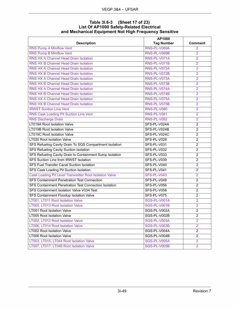
3I-49 Revision 7
VEGP 3&4 – UFSAR
RNS Pump A Miniflow Vent RNS-PL-V069A 2
RNS Pump B Miniflow Vent RNS-PL-V069B 2
RNS HX A Channel Head Drain Isolation RNS-PL-V071A 2
RNS HX B Channel Head Drain Isolation RNS-PL-V071B 2
RNS HX A Channel Head Drain Isolation RNS-PL-V072A 2
RNS HX B Channel Head Drain Isolation RNS-PL-V072B 2
RNS HX A Channel Head Drain Isolation RNS-PL-V073A 2
RNS HX B Channel Head Drain Isolation RNS-PL-V073B 2
RNS HX A Channel Head Drain Isolation RNS-PL-V074A 2
RNS HX B Channel Head Drain Isolation RNS-PL-V074B 2
RNS HX A Channel Head Drain Isolation RNS-PL-V075A 2
RNS HX B Channel Head Drain Isolation RNS-PL-V075B 2
IRWST Suction Line Vent RNS-PL-V080 2
RNS Cask Loading Pit Suction Line Vent RNS-PL-V081 2
RNS Discharge Drain RNS-PL-V082 2
LT019A Root Isolation Valve SFS-PL-V024A 2
LT019B Root Isolation Valve SFS-PL-V024B 2
LT019C Root Isolation Valve SFS-PL-V024C 2
LT020 Root Isolation Valve SFS-PL-V028 2
SFS Refueling Cavity Drain To SGS Compartment Isolation SFS-PL-V031 2
SFS Refueling Cavity Suction Isolation SFS-PL-V032 2
SFS Refueling Cavity Drain to Containment Sump Isolation SFS-PL-V033 2
SFS Suction Line from IRWST Isolation SFS-PL-V039 2
SFS Fuel Transfer Canal Suction Isolation SFS-PL-V040 2
SFS Cask Loading Pit Suction Isolation SFS-PL-V041 2
Cask Loading Pit Level Transmitter Root Isolation Valve SFS-PL-V043 2
SFS Containment Penetration Test Connection SFS-PL-V048 2
SFS Containment Penetration Test Connection Isolation SFS-PL-V056 2
SFS Containment Isolation Valve V034 Test SFS-PL-V058 2
SFS Containment Floodup Isolation Valve SFS-PL-V075 2
LT001, LT011 Root Isolation Valve SGS-PL-V001A 2
LT005, LT013 Root Isolation Valve SGS-PL-V001B 2
LT001 Root Isolation Valve SGS-PL-V002A 2
LT005 Root Isolation Valve SGS-PL-V002B 2
LT002, LT012 Root Isolation Valve SGS-PL-V003A 2
LT006, LT014 Root Isolation Valve SGS-PL-V003B 2
LT002 Root Isolation Valve SGS-PL-V004A 2
LT006 Root Isolation Valve SGS-PL-V004B 2
LT003, LT015, LT044 Root Isolation Valve SGS-PL-V005A 2
LT007, LT017, LT046 Root Isolation Valve SGS-PL-V005B 2
Table 3I.6-3 (Sheet 17 of 23)List Of AP1000 Safety-Related Electrical
and Mechanical Equipment Not High Frequency Sensitive
DescriptionAP1000
Tag Number Comment

3I-50 Revision 7
VEGP 3&4 – UFSAR
LT003 Root Isolation Valve SGS-PL-V006A 2
LT007 Root Isolation Valve SGS-PL-V006B 2
LT004, LT016, LT045 Root Isolation Valve SGS-PL-V007A 2
LT008, LT018, LT047 Root Isolation Valve SGS-PL-V007B 2
LT004 Root Isolation Valve SGS-PL-V008A 2
LT008 Root Isolation Valve SGS-PL-V008B 2
LT011 Root Isolation Valve SGS-PL-V010A 2
LT013 Root Isolation Valve SGS-PL-V010B 2
LT011 Root Isolation Valve SGS-PL-V011A 2
LT013 Root Isolation Valve SGS-PL-V011B 2
LT012 Root Isolation Valve SGS-PL-V012A 2
LT014 Root Isolation Valve SGS-PL-V012B 2
LT012 Root Isolation Valve SGS-PL-V013A 2
LT014 Root Isolation Valve SGS-PL-V013B 2
FT021 Root Isolation Valve SGS-PL-V015A 2
FT023 Root Isolation Valve SGS-PL-V015B 2
FT020 Root Isolation Valve SGS-PL-V016A 2
FT022 Root Isolation Valve SGS-PL-V016B 2
FT021 Root Isolation Valve SGS-PL-V017A 2
FT023 Root Isolation Valve SGS-PL-V017B 2
FT020 Root Isolation Valve SGS-PL-V018A 2
FT022 Root Isolation Valve SGS-PL-V018B 2
Main Steam Line Vent Isolation SGS-PL-V019A 2
Main Steam Line Vent Isolation SGS-PL-V019B 2
FT024 Root Isolation Valve SGS-PL-V020A 2
FT025 Root Isolation Valve SGS-PL-V020B 2
FT024 Root Isolation Valve SGS-PL-V021A 2
FT025 Root Isolation Valve SGS-PL-V021B 2
PT030 Root Isolation Valve SGS-PL-V022A 2
PT034 Root Isolation Valve SGS-PL-V022B 2
PT031 Root Isolation Valve SGS-PL-V023A 2
PT035 Root Isolation Valve SGS-PL-V023B 2
PT032 Root Isolation Valve SGS-PL-V024A 2
PT036 Root Isolation Valve SGS-PL-V024B 2
PT033 Root Isolation Valve SGS-PL-V025A 2
PT037 Root Isolation Valve SGS-PL-V025B 2
Steam Line 1 Nitrogen Supply Isolation SGS-PL-V038A 2
Steam Line 2 Nitrogen Supply Isolation SGS-PL-V038B 2
MSIV Bypass Control Isolation SGS-PL-V042A 2
MSIV Bypass Control Isolation SGS-PL-V042B 2
MSIV Bypass Control Isolation SGS-PL-V043A 2
MSIV Bypass Control Isolation SGS-PL-V043B 2
Table 3I.6-3 (Sheet 18 of 23)List Of AP1000 Safety-Related Electrical
and Mechanical Equipment Not High Frequency Sensitive
DescriptionAP1000
Tag Number Comment

3I-51 Revision 7
VEGP 3&4 – UFSAR
SG1 Condensate Pipe Drain Valve SGS-PL-V045A 2
SG2 Condensate Pipe Drain Valve SGS-PL-V045B 2
LT015 Root Isolation Valve SGS-PL-V046A 2
LT017 Root Isolation Valve SGS-PL-V046B 2
LT015, LT044 Root Isolation Valve SGS-PL-V047A 2
LT017, LT046 Root Isolation Valve SGS-PL-V047B 2
LT016 Root Isolation Valve SGS-PL-V048A 2
LT018 Root Isolation Valve SGS-PL-V048B 2
LT016, LT045 Root Isolation Valve SGS-PL-V049A 2
LT018, LT047 Root Isolation Valve SGS-PL-V049B 2
LT044 Root Isolation Valve SGS-PL-V050A 2
LT046 Root Isolation Valve SGS-PL-V050B 2
LT044 Root Isolation Valve SGS-PL-V051A 2
LT046 Root Isolation Valve SGS-PL-V051B 2
LT045 Root Isolation Valve SGS-PL-V052A 2
LT047 Root Isolation Valve SGS-PL-V052B 2
LT045 Root Isolation Valve SGS-PL-V053A 2
LT047 Root Isolation Valve SGS-PL-V053B 2
PT062 Root Isolation Valve SGS-PL-V056A 2
PT063 Root Isolation Valve SGS-PL-V056B 2
Main Feedwater Check SGS-PL-V058A 2
Main Feedwater Check SGS-PL-V058B 2
FT055A Root Isolation Valve SGS-PL-V062A 2
FT056A Root Isolation Valve SGS-PL-V062B 2
FT055A Root Isolation Valve SGS-PL-V063A 2
FT056A Root Isolation Valve SGS-PL-V063B 2
FT055B Root Isolation Valve SGS-PL-V064A 2
FT056B Root Isolation Valve SGS-PL-V064B 2
FT055B Root Isolation Valve SGS-PL-V065A 2
FT056B Root Isolation Valve SGS-PL-V065B 2
FT055 Root Isolation Valve SGS-PL-V066A 2
FT056 Root Isolation Valve SGS-PL-V066B 2
FT055 Root Isolation Valve SGS-PL-V068A 2
FT056 Root Isolation Valve SGS-PL-V068B 2
SG 1 Blowdown Vent Line Isolation SGS-PL-V076A 2
SG 2 Blowdown Vent Line Isolation SGS-PL-V076B 2
SG1 Nitrogen Sparging Isolation SGS-PL-V084A 2
SG2 Nitrogen Sparging Isolation SGS-PL-V084B 2
Orifice Isolation Valve SGS-PL-V093A 2
Orifice Isolation Valve SGS-PL-V093B 2
Orifice Cleanout Line Isolation Valve SGS-PL-V094A 2
Orifice Cleanout Line Isolation Valve SGS-PL-V094B 2
Orifice Isolation Valve SGS-PL-V095A 2
Orifice Isolation Valve SGS-PL-V095B 2
Table 3I.6-3 (Sheet 19 of 23)List Of AP1000 Safety-Related Electrical
and Mechanical Equipment Not High Frequency Sensitive
DescriptionAP1000
Tag Number Comment
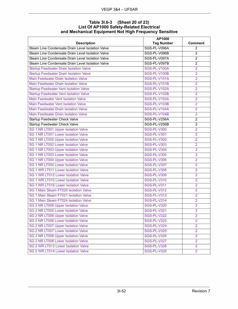
3I-52 Revision 7
VEGP 3&4 – UFSAR
Steam Line Condensate Drain Level Isolation Valve SGS-PL-V096A 2
Steam Line Condensate Drain Level Isolation Valve SGS-PL-V096B 2
Steam Line Condensate Drain Level Isolation Valve SGS-PL-V097A 2
Steam Line Condensate Drain Level Isolation Valve SGS-PL-V097B 2
Startup Feedwater Drain Isolation Valve SGS-PL-V100A 2
Startup Feedwater Drain Isolation Valve SGS-PL-V100B 2
Main Feedwater Drain Isolation Valve SGS-PL-V101A 2
Main Feedwater Drain Isolation Valve SGS-PL-V101B 2
Startup Feedwater Vent Isolation Valve SGS-PL-V102A 2
Startup Feedwater Vent Isolation Valve SGS-PL-V102B 2
Main Feedwater Vent Isolation Valve SGS-PL-V103A 2
Main Feedwater Vent Isolation Valve SGS-PL-V103B 2
Main Feedwater Drain Isolation Valve SGS-PL-V104A 2
Main Feedwater Drain Isolation Valve SGS-PL-V104B 2
Startup Feedwater Check Valve SGS-PL-V256A 2
Startup Feedwater Check Valve SGS-PL-V256B 2
SG 1 NR LT001 Upper Isolation Valve SGS-PL-V300 2
SG 1 NR LT001 Lower Isolation Valve SGS-PL-V301 2
SG 1 NR LT002 Upper Isolation Valve SGS-PL-V302 2
SG 1 NR LT002 Lower Isolation Valve SGS-PL-V303 2
SG 1 NR LT003 Upper Isolation Valve SGS-PL-V304 2
SG 1 NR LT003 Lower Isolation Valve SGS-PL-V305 2
SG 1 NR LT004 Upper Isolation Valve SGS-PL-V306 2
SG 1 NR LT004 Lower Isolation Valve SGS-PL-V307 2
SG 1 WR LT011 Lower Isolation Valve SGS-PL-V308 2
SG 1 WR LT012 Lower Isolation Valve SGS-PL-V309 2
SG 1 WR LT015 Lower Isolation Valve SGS-PL-V310 2
SG 1 WR LT016 Lower Isolation Valve SGS-PL-V311 2
SG 1 Main Steam FT020 Isolation Valve SGS-PL-V312 2
SG 1 Main Steam FT021 Isolation Valve SGS-PL-V313 2
SG 1 Main Steam FT024 Isolation Valve SGS-PL-V314 2
SG 2 NR LT005 Upper Isolation Valve SGS-PL-V320 2
SG 2 NR LT005 Lower Isolation Valve SGS-PL-V321 2
SG 2 NR LT006 Upper Isolation Valve SGS-PL-V322 2
SG 2 NR LT006 Lower Isolation Valve SGS-PL-V323 2
SG 2 NR LT007 Upper Isolation Valve SGS-PL-V324 2
SG 2 NR LT007 Lower Isolation Valve SGS-PL-V325 2
SG 2 NR LT008 Upper Isolation Valve SGS-PL-V326 2
SG 2 NR LT008 Lower Isolation Valve SGS-PL-V327 2
SG 2 WR LT013 Lower Isolation Valve SGS-PL-V328 2
SG 2 WR LT014 Lower Isolation Valve SGS-PL-V329 2
Table 3I.6-3 (Sheet 20 of 23)List Of AP1000 Safety-Related Electrical
and Mechanical Equipment Not High Frequency Sensitive
DescriptionAP1000
Tag Number Comment

3I-53 Revision 7
VEGP 3&4 – UFSAR
SG 2 WR LT017 Lower Isolation Valve SGS-PL-V330 2
SG 2 WR LT018 Lower Isolation Valve SGS-PL-V331 2
SG 2 Main Steam FT022 Isolation Valve SGS-PL-V332 2
SG 2 Main Steam FT023 Isolation Valve SGS-PL-V333 2
SG 2 Main Steam FT025 Isolation Valve SGS-PL-V334 2
Air Delivery Line Pressure Instrument Isolation Valve A VES-PL-V006A 2
Air Delivery Line Pressure Instrument Isolation Valve B VES-PL-V006B 2
Air Delivery Line Maintenance Isolation Valve A VES-PL-V010A 2
Air Delivery Line Maintenance Isolation Valve B VES-PL-V010B 2
Air Delivery Line Maintenance Isolation Valve A VES-PL-V011A 2
Air Delivery Line Maintenance Isolation Valve B VES-PL-V011B 2
Temporary Instrument Isolation Valve A VES-PL-V016 2
Temporary Instrument Isolation Valve B VES-PL-V020 2
Air Bank 1 Isolation Valve A VES-PL-V024A 2
Air Bank 2 Isolation Valve B VES-PL-V024B 2
Air Bank 3 Isolation Valve C VES-PL-V024C 2
Air Bank 4 Isolation Valve D VES-PL-V024D 2
Air Bank 1 Isolation Valve A VES-PL-V025A 2
Air Bank 2 Isolation Valve B VES-PL-V025B 2
Air Bank 3 Isolation Valve C VES-PL-V025C 2
Air Bank 4 Isolation Valve D VES-PL-V025D 2
Air Bank 1 Fill/Vent Isolation Valve A VES-PL-V026A 2
Air Bank 2 Fill/Vent Isolation Valve B VES-PL-V026B 2
Air Bank 3 Fill/Vent Isolation Valve C VES-PL-V026C 2
Air Bank 4 Fill/Vent Isolation Valve D VES-PL-V026D 2
DP Instrument Line Isolation Valve A VES-PL-V043A 2
DP Instrument Line Isolation Valve B VES-PL-V043B 2
Containment Isolation Test Connection VFS-PL-V006 2
RCS Ejector Discharge Isolation VFS-PL-V007 2
Containment Isolation Test Connection VFS-PL-V008 2
Containment Isolation Test Connection VFS-PL-V012 2
Containment Isolation Test Connection VFS-PL-V015 2
Containment Isolation Test Connection VFS-PL-V101 2
Containment Atmosphere to Filtration Units Isolation VFS-PL-V202 2
Filtration Units to Containment Atmosphere Manual Isolation VFS-PL-V587 2
Main Equipment Hatch Test Connection VUS-PL-V013 2
Maintenance Equipment Hatch Test Connection VUS-PL-V014 2
Main Equipment Hatch Test Connection VUS-PL-V015 2
Table 3I.6-3 (Sheet 21 of 23)List Of AP1000 Safety-Related Electrical
and Mechanical Equipment Not High Frequency Sensitive
DescriptionAP1000
Tag Number Comment
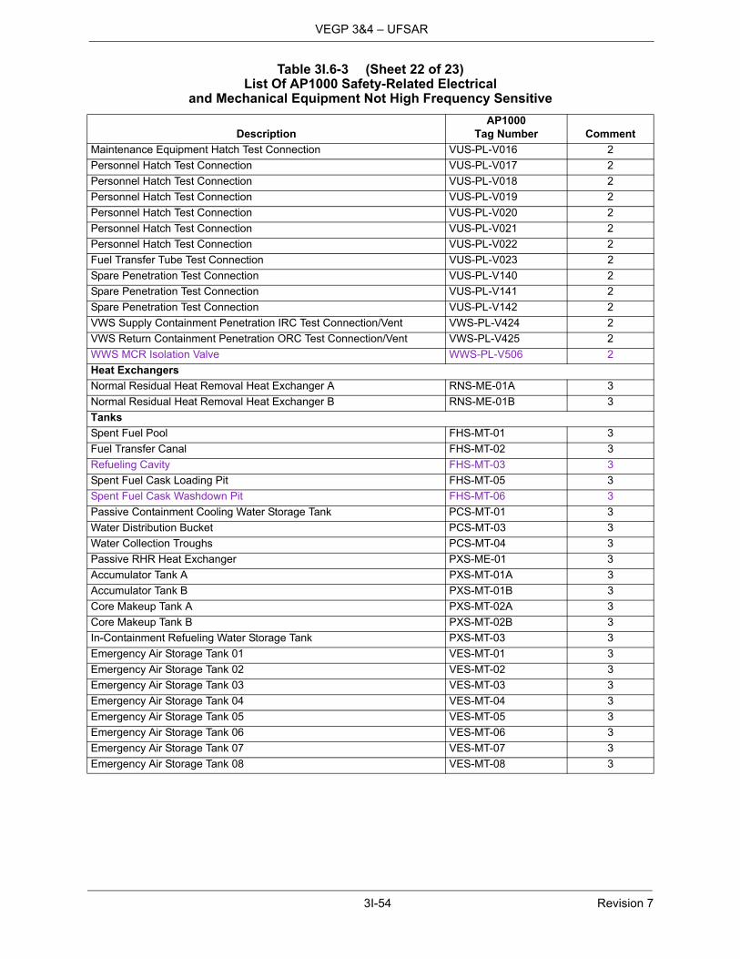
3I-54 Revision 7
VEGP 3&4 – UFSAR
Maintenance Equipment Hatch Test Connection VUS-PL-V016 2
Personnel Hatch Test Connection VUS-PL-V017 2
Personnel Hatch Test Connection VUS-PL-V018 2
Personnel Hatch Test Connection VUS-PL-V019 2
Personnel Hatch Test Connection VUS-PL-V020 2
Personnel Hatch Test Connection VUS-PL-V021 2
Personnel Hatch Test Connection VUS-PL-V022 2
Fuel Transfer Tube Test Connection VUS-PL-V023 2
Spare Penetration Test Connection VUS-PL-V140 2
Spare Penetration Test Connection VUS-PL-V141 2
Spare Penetration Test Connection VUS-PL-V142 2
VWS Supply Containment Penetration IRC Test Connection/Vent VWS-PL-V424 2
VWS Return Containment Penetration ORC Test Connection/Vent VWS-PL-V425 2
WWS MCR Isolation Valve WWS-PL-V506 2
Heat Exchangers
Normal Residual Heat Removal Heat Exchanger A RNS-ME-01A 3
Normal Residual Heat Removal Heat Exchanger B RNS-ME-01B 3
Tanks
Spent Fuel Pool FHS-MT-01 3
Fuel Transfer Canal FHS-MT-02 3
Refueling Cavity FHS-MT-03 3
Spent Fuel Cask Loading Pit FHS-MT-05 3
Spent Fuel Cask Washdown Pit FHS-MT-06 3
Passive Containment Cooling Water Storage Tank PCS-MT-01 3
Water Distribution Bucket PCS-MT-03 3
Water Collection Troughs PCS-MT-04 3
Passive RHR Heat Exchanger PXS-ME-01 3
Accumulator Tank A PXS-MT-01A 3
Accumulator Tank B PXS-MT-01B 3
Core Makeup Tank A PXS-MT-02A 3
Core Makeup Tank B PXS-MT-02B 3
In-Containment Refueling Water Storage Tank PXS-MT-03 3
Emergency Air Storage Tank 01 VES-MT-01 3
Emergency Air Storage Tank 02 VES-MT-02 3
Emergency Air Storage Tank 03 VES-MT-03 3
Emergency Air Storage Tank 04 VES-MT-04 3
Emergency Air Storage Tank 05 VES-MT-05 3
Emergency Air Storage Tank 06 VES-MT-06 3
Emergency Air Storage Tank 07 VES-MT-07 3
Emergency Air Storage Tank 08 VES-MT-08 3
Table 3I.6-3 (Sheet 22 of 23)List Of AP1000 Safety-Related Electrical
and Mechanical Equipment Not High Frequency Sensitive
DescriptionAP1000
Tag Number Comment

3I-55 Revision 7
VEGP 3&4 – UFSAR
Notes:1. Rugged AP1000 safety-related equipment with no moving parts required in demonstrating functional operability during a seismic
event is considered to be not sensitive to HRHF seismic loadings. Seismic qualification is based on the seismic loads associated with the mounting location of the safety-related equipment as a minimum. AP1000 CSDRS seismic loads at the mounting location of the safety-related equipment produces comparable or higher equipment stresses and deflections than the HRHF seismic loadings based on the work reported in APP-GW-GLR-115, “Effect of High Frequency Seismic Content on SSCs.” For rugged safety-related line-mounted equipment being qualified by test, seismic testing will be performed in compliance with IEEE Standard 382-1996 with a required input motion (RIM) curve extended to 64 Hz typically to a peak acceleration of 6g.
2. AP1000 safety-related valves are seismic qualified in accordance with ASME code for structural integrity to a maximumacceleration of 6g in all three principal orthogonal axes. AP1000 CSDRS seismic loads at the mounting location of the safety-related equipment produce comparable or higher equipment stresses and deflections than the HRHF seismic loadings based on the work reported in APP-GW-GLR-115, “Effect of High Frequency Seismic Content on SSCs.” For rugged safety-related line-mounted equipment being qualified by test, seismic testing will be performed in compliance with IEEE Standard 382-1996 with a required input motion (RIM) curve extended to 64 Hz typically to a peak acceleration of 6g.
3. Seismic qualification is based on structural integrity alone to the seismic loadings associated with the mounting location of thesafety-related equipment as a minimum. AP1000 CSDRS seismic loads at the mounting location of the safety-related equipment produce comparable or higher equipment stresses and deflections than the HRHF seismic loadings based on the work reported in APP-GW-GLR-115, “Effect of High Frequency Seismic Content on SSCs.”
Emergency Air Storage Tank 09 VES-MT-09 3
Emergency Air Storage Tank 10 VES-MT-10 3
Emergency Air Storage Tank 11 VES-MT-11 3
Emergency Air Storage Tank 12 VES-MT-12 3
Emergency Air Storage Tank 13 VES-MT-13 3
Emergency Air Storage Tank 14 VES-MT-14 3
Emergency Air Storage Tank 15 VES-MT-15 3
Emergency Air Storage Tank 16 VES-MT-16 3
Emergency Air Storage Tank 17 VES-MT-17 3
Emergency Air Storage Tank 18 VES-MT-18 3
Emergency Air Storage Tank 19 VES-MT-19 3
Emergency Air Storage Tank 20 VES-MT-20 3
Emergency Air Storage Tank 21 VES-MT-21 3
Emergency Air Storage Tank 22 VES-MT-22 3
Emergency Air Storage Tank 23 VES-MT-23 3
Emergency Air Storage Tank 24 VES-MT-24 3
Emergency Air Storage Tank 25 VES-MT-25 3
Emergency Air Storage Tank 26 VES-MT-26 3
Emergency Air Storage Tank 27 VES-MT-27 3
Emergency Air Storage Tank 28 VES-MT-28 3
Emergency Air Storage Tank 29 VES-MT-29 3
Emergency Air Storage Tank 30 VES-MT-30 3
Emergency Air Storage Tank 31 VES-MT-31 3
Emergency Air Storage Tank 32 VES-MT-32 3
Table 3I.6-3 (Sheet 23 of 23)List Of AP1000 Safety-Related Electrical
and Mechanical Equipment Not High Frequency Sensitive
DescriptionAP1000
Tag Number Comment

3I-56 Revision 7
VEGP 3&4 – UFSAR
Figure 3I.1-1Comparison of Horizontal AP1000 CSDRS and HRHF Envelope Response Spectra
AP1000 Horizontal Spectra Comparison
0.00
0.10
0.20
0.30
0.40
0.50
0.60
0.70
0.80
0.90
1.00
0.1 1 10 100
Frequency (Hz)
Acc
eler
atio
n (g
)
HRHF GMRS
AP1000 CSDRS

3I-57 Revision 7
VEGP 3&4 – UFSAR
Figure 3I.1-2Comparison of Vertical AP1000 CSDRS and HRHF Envelope Response Spectra
AP1000 Vertical Spectra Comparison
0.00
0.10
0.20
0.30
0.40
0.50
0.60
0.70
0.80
0.90
1.00
0.1 1 10 100
Frequency (Hz)
Acc
eler
atio
n (g
)
HRHF GMRS
AP1000 CSDRS