appendices for south huron valley wwtp priority 1 …
TRANSCRIPT
APPENDICES
FOR
SOUTH HURON VALLEY WWTP PRIORITY 1 AND 2 IMPROVEMENTS PROJECT
SOUTH HURON VALLEY UTILITY AUTHORITY WAYNE COUNTY, MICHIGAN
ISSUED FOR BIDS MARCH 26, 2021
HRC JOB NO. 20190897.07
535 Griswold, Suite 1650 Detroit, Michigan 48226

SOUTH HURON VALLEY UTILLITY AUTHORITY SHVUE PRIORITY 1 AND 2 IMPROVEMENTS PROJECT
Hubbell, Roth & Clark, Inc. Job 20190897
APPENDIX A
Stacked Tray Proposal

Budget PricingProject Name: South Huron Valley, MI Date Prepared: 10/5/2020Project Number: 20_11_0022 Ar1 Validity: 30 days from issue.
Engineer Firm: Hubbell, Roth & Clarke, Inc.
Equipment Quantity Price
2
2
2
2
2
3
2
1
1
Primary Grit Removal 27.5 mgd/unit
12 ft. 11 Tray 125 micron HeadCell® Grit Removal unit
HeadCell® inlet flow distribution header, 304 Stainless Steel
Fluidizing ring, 304 Stainless Steel
Grit Dewatering
GritCleanse®: 304 Stainless Steel, up to 1.5 yd³/hr, 12” Screw, 84”
Clarifier Complete with drive units, valves
Control PanelMicroLogix 1400 PLC, PV 6" OIU, NEMA 4X, 304SS, VFDs
PumpDry Pit, Horizontal Mount, Recessed Impeller, 300 gpm Grit Pump
Start UpOne (1) factory representative for two (2) trips for a total of four (4) days
Freight
Total Proposal Budget Price: $826,000.00
Terms & Conditions: As defined by Hydro International standard Terms & Conditions.
After expiration of validity Hydro International reserves the right to adjust pricing to account for any significant increases in material costs.
$413,000.00
$331,000.00
$82,000.00
SOUTH HURON VALLEY UTILLITY AUTHORITY SHVUE PRIORITY 1 AND 2 IMPROVEMENTS PROJECT
Hubbell, Roth & Clark, Inc. Job 20190897
APPENDIX B
Plant SCADA Upgrade
Outbound Technologies
Confidential Outbound Proposal 20-P1164E
SHVUA – Plant SCADA Upgrade March 12, 2021
Approved By: CAJ – 3/12/21 Page 1 of 13
30026 Research Drive New Hudson, Michigan 48165 (248) 735-5000 (248) 735-5001 Fax
South Huron Valley Utility Authority
Plant SCADA Upgrade
South Huron Valley Utility Authority
Proposal #: 20-P1164E Date: March 15th, 2021
Outbound Technologies, Inc. Controls System Integrator
Submitted To:
General Contractor
From:
Chris Tury Jr.
General Manager – Michigan Operations Outbound Technologies, Inc.
Outbound Technologies
Confidential Outbound Proposal 20-P1164E
SHVUA – Plant SCADA Upgrade March 12, 2021
Approved By: CAJ – 3/12/21 Page 2 of 13
OVERVIEW
The intent of this project is to replace the antiquated existing SCADA software at the South Huron Valley Utility Authority (SHVUA) Wastewater Treatment Plant in Brownstown, Michigan. The SCADA system is currently operating using two Wonderware Historian servers for data storage and trending. The SCADA HMI is written in Visual Basic 6.0, which hit Microsoft’s primary End of Life in 2005, although it was extended to 2008. The SCADA communication was upgraded from DDE to OPC in 2012, which allowed it to work for a few more years, but it needs to be replaced with a modern SCADA system. The system will have two servers with FT View SE Server installed. The servers will be configured to operate as a primary and backup redundant pair, so the client nodes only need to be configured to communicate with the primary server. If the primary server goes down, the backup server will take its place. The client computers will be desktop models for operators/staff and full Windows 10 panel mounted PCs for the touch screen nodes installed near the panels around the plant. The SCADA computers will need FT View SE installed along with the SCADA application and RSLinx. They will execute the application and communicate directly with the PLCs. The panel mount computers will be configured to communicate with their local PLC directly and all other plant PLCs though the server’s RSLinx Gateway connection to reduce the amount of communication on the network and to each PLC. Historical data will be stored in a SQL Server database on each server redundantly. It will be accessed through the historical trend tool within FT View SE and through the provided reporting tool Dream Report by Ocean Data Systems. Up to (5) reports will be created in Dream Report and will be available through the DR Web portal using only a web browser. Reports can be scheduled to run automatically and emailed to users when they are complete. Outbound Technologies’ (OTI) scope of work on this project includes the following:
• Manufacturer’s literature compilation • SCADA software engineering • Custom software engineering • Capital equipment specification, procurement, and shipping services • Start-up and validation services • At the conclusion of verification testing on all operations, submit all programs and
documentation. OTI employs over (50) engineers across Michigan, Indiana, and Ohio. Additionally, OTI has completed thousands of controls projects in several different industries. OTI possesses the resources and expertise to deliver this project on-time, on-budget while exceeding our customer’s expectations.

Outbound Technologies
Confidential Outbound Proposal 20-P1164E
SHVUA – Plant SCADA Upgrade March 12, 2021
Approved By: CAJ – 3/12/21 Page 3 of 13
BASIS
The basis for this proposal is OTI’s understanding and interpretation of the following:
• Customer-provided scope of work, specifications, etc. including: • Pages from 20190415_FINAL-Rev1_5ys_CIP_20190416.pdf
SCOPE
OTI’s understanding of the project responsibilities is detailed in the matrix below:
PROJECT RESPONSIBILITY MATRIX
TASK RESPONSIBILITY OTI CUST. OTHER NOTES Purchase Order
Project Management
Reference Design Documents As Required.
Sequence of Operations
Electrical Engineering N/A
Software Engineering
• PLC N/A
• HMI
• Robot N/A
• PC / Custom
Capital Equipment - Electrical
• Main Disconnect Enclosure N/A
• HMI Enclosure N/A
• Field Devices & Sensors N/A
• Wire & Cable
Field Supervisory Services
Mechanical Installation Services
Electrical Installation Services
Start-Up & Commissioning
Functional Acceptance Testing N/A
Training Services
Stand-by Services N/A
Design Approvals
Project Kick-Off
Prior to commencing work on this project, OTI requires the following from SHVUA: • Detailed pre-award meeting • Hard copy purchase order • Integration requirements for existing systems and databases
Outbound Technologies
Confidential Outbound Proposal 20-P1164E
SHVUA – Plant SCADA Upgrade March 12, 2021
Approved By: CAJ – 3/12/21 Page 4 of 13
Once this information has been provided, OTI will supply SHVUA with the following:
• Detailed schedule • Open issues list
Manufacturer Product Information
Manufacturer product information will be supplied for all system elements specified by OTI.
SCADA Software Engineering
OTI will supply the following custom software engineering services: • Consistent with the existing system operation, OTI will design and implement the
SCADA software application. The existing SCADA screens will be used as rough templates for the upgraded screens. All screens will be upgraded to a more modern and consistent look and feel. • OTI estimates there will be a total of over (100) screens created based on the exiting
application. • (2) FT View SE Servers will be built, tested, and commissioned at the plant. • (6) Mini desktop computers will be built, tested, and commissioned at the plant. • (5) Panel mount SCADA computers will be built, tested, and commissioned at the plant. • (1) Mini desktop computer will be built, tested, and commissioned at Trenton Arm. • (1) Panel mount SCADA computer will be built, tested, and commissioned at Trenton
Arm lift station. • A stand-alone version (15 screen) of FT View SE will be installed on the Trenton
Arm panel mount computer. This node will only be allowed to communicate with the PLC at Trenton Arm, not the rest of the main plant.
• Configure historical logging to the SQL Server database from within FT View SE on both servers.
• Install, configure, and commission Dream Report on the primary server. This will not have a redundant configuration, so if the primary server fails, the license will need to be installed to the backup server to create and run reports. • Up to (5) static reports will be configured using a date range selection as a report
parameter. • Upgrade of the existing fiberoptic network. Every fiber link in the plant will be
individually evaluated and upgraded to 1GB if the fiber will support it. If it will not, that link will be upgraded to 100MB.
• Network upgrades will also include adding a StarTech Rack Media Chassis and replacing the (10) existing network failover switches with new Shore Micro 1GB failover switches. Any new 1GB fiber converters will also require new ST-SC fiber patch cables.
Electrical Contractor Requirements Some of the activities that OTI will be performing for this project will require the support and assistance of the electrical contractor. These items include:
Outbound Technologies
Confidential Outbound Proposal 20-P1164E
SHVUA – Plant SCADA Upgrade March 12, 2021
Approved By: CAJ – 3/12/21 Page 5 of 13
• Mount the (6) new panel mounted HMIs in the existing enclosures around the plant and at Trenton Arm Lift Station.
o This may require modification to the existing panel cut out if the new panel is a different size. If an adapter plate is required, it will be provided by OTI and installed by the electrical contractor.
o The remaining computers and network equipment listed in this proposal will be installed by OTI.
o Any other computers, network equipment or HMIs in the bid pack are the responsibility of others.
• A Cat6 network cable must be pulled from the network switch in the PLC panel to the enclosed office inside Trenton Arm Lift station. Terminate with a modular Cat6 female box inside the office.
Capital Equipment
OTI will supply the following capital equipment:
• (2) Dell r740 - Servers • Windows Server 2019 Standard
o (10) User Client Access Licenses • Xeon Silver 4210 CPU • 32 GB RAM • 960GB SATA SSD Hard Drive (4)
o (4) drives total, configured in RAID 10 • DVD/RW Drive • Microsoft SQL Server 2019 Standard OEM
o (10) User Client Access Licenses • (3) Years Pro Support
• (7) Dell Optiplex 5070 - Desktop Computer • Windows 10 Pro • Intel Core i5-9500 CPU • 8 GB RAM • 128GB M2 SSD Hard Drive • 3 Years Pro Support
• (9) Viewsonic VA2446mh - 24” 1080p Monitor • (6) Advantech UNO-2484G-6531 - Industrial PC
• Windows 10 Pro • Intel Core i5-6300 CPU • 8 GB RAM • 500GB SATA Hard Drive
• (6) Advantech FPM-215W-P4AE - 15” Panel Mount Monitor • (2) Cisco SF250-24 Managed 24 Port Network Switch
• Includes (2) Gigabit Fiber ST SPF modules • (2) APC SMX2000LV - Smart UPS 2000 Uninterruptible Power Supply • (1) Rockwell Software 9701M-VWSSPT30 – FactoryTalk View Studio Enterprise

Outbound Technologies
Confidential Outbound Proposal 20-P1164E
SHVUA – Plant SCADA Upgrade March 12, 2021
Approved By: CAJ – 3/12/21 Page 6 of 13
• (2) Rockwell Software 9701M-VWSSPT10 - FactoryTalk SE Server w/10 Clients • (1) Rockwell Software 9701M-VWSTNST50 - FT View SE Station 15 Screen • (1) Year Tech Connect subscription for the Rockwell Software above • (1) Dream Report – 250 Tag License (includes 1 Web Client License) • (2) Dream Report Web Client License (3 total) • (1) Year Dream Report Annual Support • (10) Shore Micro SM-2501G Gigabit Failover Switch • (38) StarTech ET91000SC2 Gigabit SC Fiber Converter
o For 100MB connections, this will be replaced with StarTech ET90110ST2 • (2) StarTech ETCHS2U Rack Media Mount Chassis • (38) ST/SC Fiber Patch Cables
Start-Up and Commissioning Services
All start-up and commissioning services will be provided based on (1) engineer, (8) hours per day.
• In cooperation with the installing skilled trades, OTI will provide a documented field check of all system functionality as intended.
• Configuration of the camera and related equipment. • Test and demonstrate system features and functions. • Test and demonstrate system alarm paging. • Test and demonstrate the system reporting ability.
o Note: The testing described above will entail the “debug” of custom software and other software programs as applicable. Outbound will arrive at the start-up site with software that has been designed and coded, but this does not equate to “perfect” bug free code. SHVUA accepts and understands that the proposed window of time for start-up and commissioning will include effort on the part of Outbound personnel to conclude debug of the software, and to install corrections, enhancements, and additions as determined required during the commissioning of the automation equipment or system.
• Communication of all job site open issues via an open issues list. The open issues list will be delivered to SHVUA via email.
• Communication of all weekly activities via a weekly field report. Weekly field reports will be delivered to SHVUA via email.
• Test and demonstrate the system’s capabilities under run-off conditions. In conjunction with OTI’s supplied check-out forms, this run-off will represent SHVUA acceptance of the system.
This proposal assumes that the mechanical and electrical installation of the manufacturing process and related control systems will be significantly complete prior to OTI’s arrival at the job site. In this context, “significant” includes all of the following:
• 100% of all electrical field devices have their associated wiring terminated in the building and in the field.
Outbound Technologies
Confidential Outbound Proposal 20-P1164E
SHVUA – Plant SCADA Upgrade March 12, 2021
Approved By: CAJ – 3/12/21 Page 7 of 13
Additional compensation will be required in the event OTI arrives for commissioning without the above being complete. Additionally, supervision of the installing electrical contractor is not included in this proposal and OTI’s commissioning time is not allotted for this use.
Training Services
This proposal excludes formal training activities. Training supplied to SHV personnel will be informal and hands-on and will take place during the commissioning and validation.
DOCUMENTATION
Project and Design Software Platforms
OTI will utilize the following software platforms for this project: Text, Spreadsheet, Reporting, and Project Planning
• Microsoft Word • Microsoft Excel
HMI Software Design
• FactoryTalk View SE, version (version 11)
Reporting Design • Dream Report (version 5)
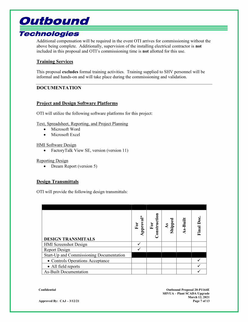
Design Transmittals
OTI will provide the following design transmittals:
DESIGN TRANSMITALS
For
App
rova
l*
For
Con
stru
ctio
n
As
Ship
ped
As-
Bui
lt
Fina
l Doc
.
HMI Screenshot Design Report Design Start-Up and Commissioning Documentation • Controls Operations Acceptance • All field reports
As-Built Documentation
Outbound Technologies
Confidential Outbound Proposal 20-P1164E
SHVUA – Plant SCADA Upgrade March 12, 2021
Approved By: CAJ – 3/12/21 Page 8 of 13
• * Written approval required.
STAFFING
Project Staff
OTI will provide the following project management staffing:
• (1) project manager to perform the following tasks: • Outbound Technologies’ point-of-contact with SHVUA • Software engineering design reviews • Ensure communication with SHVUA via meeting minutes, field reports, open issues
lists, emails, etc. • Attend all necessary engineering and commissioning meetings over the duration of
the project. OTI will provide the following project staffing:
• An optimal number of engineer(s) to perform the following tasks: • SCADA software engineering • Capital equipment and software specification, procurement, and shipping/delivery. • Start-up and commissioning services • As-built documentation
SCHEDULE
OTI and SHVUA will establish a mutually agreeable schedule upon award of contract at the project kick off meeting.
CHANGE CONTROL
The following procedure shall be adopted for any changes identified by OTI or SHVUA at any stage of the project.
• Change Request • The Change Request may be initiated due to any of the following conditions:
• Execution of a newly identified task • Changes in identified tasks • Any changes in the targeted environment
• The change identified has to be documented and communicated between OTI and SHVUA, in the form of a written document, such as an e-mail. Verbally communicated changes would need to be followed by a written request within (24) hours.
• Change Evaluation • The change will be evaluated for its impact on the project schedule, efforts, and
Outbound Technologies
Confidential Outbound Proposal 20-P1164E
SHVUA – Plant SCADA Upgrade March 12, 2021
Approved By: CAJ – 3/12/21 Page 9 of 13
commercial costs and communicated to SHVUA. • Change Approval
• All changes will have to be approved and mutually agreed upon in writing by OTI and SHVUA before they are approved for implementation. OTI shall proceed with the changes, which might impact costs and schedules, only after SHVUA communicates an approval, in writing.
RISK MANAGEMENT
Identified Project Risk Risk Mitigation Possible plant operation interruption during commissioning
OTI will coordinate with plant management and operators when testing each PLC panel update
QUALIFICATIONS
Purchaser Roles & Responsibilities
• No work or purchasing of equipment will take place without a hard copy purchase order from SHVUA.
• SHVUA to provide prompt review and approval of all design transmittals and documentation within the outline of the bid specifications. The basis for this proposal is OTI’s receipt of reviewed design submittals within ten (10) business days of transmittal. If design submittal comments are not received within this time period, the project schedule will slip day for day.
• OTI requires a detailed pre-award meeting between all the key OTI and SHVUA personnel prior to receipt of a purchase order.
• OTI requires that this proposal be referenced in SHVUA’s purchase order. • SHVUA to provide the following:
• Any and all capital equipment and engineering services required, but not specifically listed in this proposal.
• Appropriate personnel to assist in the commissioning phase of the system. This includes operation of the equipment and installation, as required.
Commercial
• OTI’s price, schedule and deliverables are wholly and solely predicated on milestone payments per the itemized pricing provided below.
• OTI’s price excludes minority content. • OTI’s price is in U.S. dollars. • Payment terms net (30) days after submittal of invoice. • This proposal is predicated on OTI’s ability to efficiently perform the project work, and
by issuing a purchase order SHVUA understands and accepts that OTI cannot be held
Outbound Technologies
Confidential Outbound Proposal 20-P1164E
SHVUA – Plant SCADA Upgrade March 12, 2021
Approved By: CAJ – 3/12/21 Page 10 of 13
liable for any unforeseen project and schedule delays due to restrictions put in place by federal or state governments due to the ongoing COVID-19 pandemic.
Capital Equipment
• OTI’s price is based on the specific manufacturers, part numbers, quantities, and sizes indicated in the “Capital Equipment” section of this proposal. OTI reserves the right to re-price based on any deviations from these items.
• Material and equipment to be provided by others: • All field wiring, including necessary quick-connect and communication cables. • All building/system lighting and associated control.
• This proposal excludes spare parts. • This proposal excludes any programming laptops.
Engineering
• Services excluded from this proposal: • Mechanical, pneumatic, and hydraulic engineering and commissioning • Electrical engineering and AutoCAD detailing • Recommended spare parts list generation • Lock-out placard engineering and generation • Arc Flash calculations and labeling • Sequence of operations development • PLC software engineering and programming • Mechanical and electrical installation supervision services • Mechanical and electrical installation • Formal training services • Stand-by services
Shipping
• OTI will provide a detailed shipper for all deliveries. Unloading and storage of the material will be the responsibility of the company signing the shipper, and OTI will not be responsible for the loss/damage of material after its delivery has taken place.
• FOB Brownstown, MI.
Miscellaneous
• All taxes (except employee taxes), licenses, permits, duties and fees associated with this project and contract are to be provided by others. This includes all IVA taxes imposed by the destination country.
• IRI and/or FM approval, documentation and submittals are to be provided by others. OTI will provide the necessary electrical drawings and sequence of operations for these submittals as required.
• OTI is offering a warranty period of (1) year. Refer to the terms and conditions for warranty details.

Outbound Technologies
Confidential Outbound Proposal 20-P1164E
SHVUA – Plant SCADA Upgrade March 12, 2021
Approved By: CAJ – 3/12/21 Page 11 of 13
COMMERCIAL
Pricing Software Engineering $ 76,275.00 Documentation & Project Management $ 5,160.00 Material & Shipping $ 122,289.00 Field Engineering $ 66,584.00 TOTAL $ 270,308.00
Pre-Award Meeting
For all OTI projects, kickoff meetings are vital to align project expectations for all parties. During these meetings, the following will be discussed:
• Ensure all project participants share contact info and that all understand their roles and obligations.
• Discuss the project schedule and all milestone dates and commitments. • Discuss the proper method for ensuring all project changes are communicated to all
project participants. • Discuss and determine proper invoicing format. • Any and all other relevant project information shall also be reviewed (i.e., scope of
work, specification adherence, etc.)
Terms & Conditions
Payment Terms: Contractual and payment terms will be negotiated with the project GC at the time of award of contract. Thank you very much for this opportunity. Sincerely, Chris Tury Jr. General Manager – Michigan Operations Outbound Technologies, Inc.
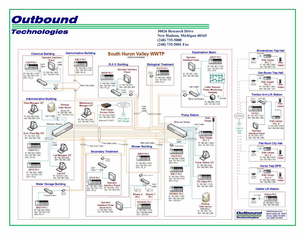
Attachment: SHV Plant Network Drawing Attachment: OTI’s Standard Schedule of Fees
Outbound Technologies
Confidential Outbound Proposal 20-P1164E
SHVUA – Plant SCADA Upgrade March 12, 2021
Approved By: CAJ – 3/12/21 Page 12 of 13
30026 Research Drive New Hudson, Michigan 48165 (248) 735-5000 (248) 735-5001 Fax

Outbound Technologies
Confidential Outbound Proposal 20-P1164E
SHVUA – Plant SCADA Upgrade March 12, 2021
Approved By: CAJ – 3/12/21 Page 13 of 13
`
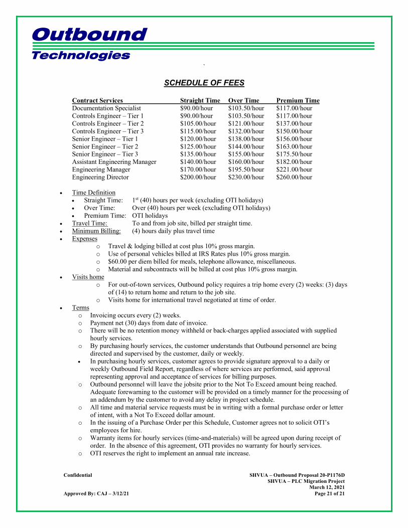
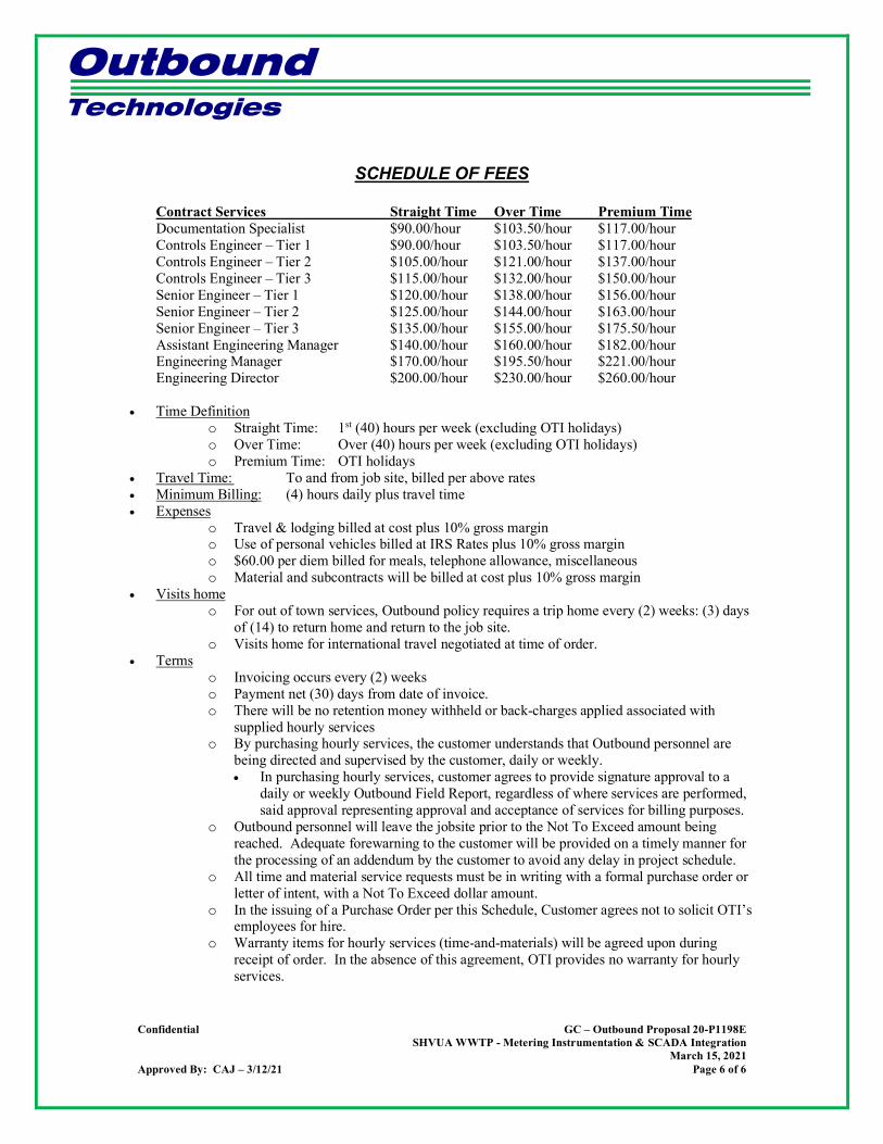
SCHEDULE OF FEES
Contract Services Straight Time Over Time Premium Time Documentation Specialist $90.00/hour $103.50/hour $117.00/hour Controls Engineer – Tier 1 $90.00/hour $103.50/hour $117.00/hour Controls Engineer – Tier 2 $105.00/hour $121.00/hour $137.00/hour Controls Engineer – Tier 3 $115.00/hour $132.00/hour $150.00/hour Senior Engineer – Tier 1 $120.00/hour $138.00/hour $156.00/hour Senior Engineer – Tier 2 $125.00/hour $144.00/hour $163.00/hour Senior Engineer – Tier 3 $135.00/hour $155.00/hour $175.50/hour Assistant Engineering Manager $140.00/hour $160.00/hour $182.00/hour Engineering Manager $170.00/hour $195.50/hour $221.00/hour Engineering Director $200.00/hour $230.00/hour $260.00/hour
• Time Definition
• Straight Time: 1st (40) hours per week (excluding OTI holidays) • Over Time: Over (40) hours per week (excluding OTI holidays) • Premium Time: OTI holidays
• Travel Time: To and from job site, billed per straight time. • Minimum Billing: (4) hours daily plus travel time • Expenses
o Travel & lodging billed at cost plus 10% gross margin. o Use of personal vehicles billed at IRS Rates plus 10% gross margin. o $60.00 per diem billed for meals, telephone allowance, miscellaneous. o Material and subcontracts will be billed at cost plus 10% gross margin.
• Visits home o For out-of-town services, Outbound policy requires a trip home every (2) weeks: (3) days
of (14) to return home and return to the job site. o Visits home for international travel negotiated at time of order.
• Terms o Invoicing occurs every (2) weeks. o Payment net (30) days from date of invoice. o There will be no retention money withheld or back-charges applied associated with supplied
hourly services. o By purchasing hourly services, the customer understands that Outbound personnel are being
directed and supervised by the customer, daily or weekly. • In purchasing hourly services, customer agrees to provide signature approval to a daily or
weekly Outbound Field Report, regardless of where services are performed, said approval representing approval and acceptance of services for billing purposes.
o Outbound personnel will leave the jobsite prior to the Not To Exceed amount being reached. Adequate forewarning to the customer will be provided on a timely manner for the processing of an addendum by the customer to avoid any delay in project schedule.
o All time and material service requests must be in writing with a formal purchase order or letter of intent, with a Not To Exceed dollar amount.
o In the issuing of a Purchase Order per this Schedule, Customer agrees not to solicit OTI’s employees for hire.
o Warranty items for hourly services (time-and-materials) will be agreed upon during receipt of order. In the absence of this agreement, OTI provides no warranty for hourly services.
o OTI reserves the right to implement an annual rate increase.

SOUTH HURON VALLEY UTILLITY AUTHORITY SHVUE PRIORITY 1 AND 2 IMPROVEMENTS PROJECT
Hubbell, Roth & Clark, Inc. Job 20190897
APPENDIX C
PLC Migration
Outbound Technologies
30026 Research Drive New Hudson, Michigan 48165 (248) 735-5000 (248) 735-5001 Fax
SHVUA WWTP Operations PLC Migration Project
South Huron Valley Utility Authority
Proposal #: 20-P1176D Date: March 15th, 2021
Outbound Technologies, Inc. Controls System Integrator
Submitted To:
General Contractor
From:
Chris Tury Jr.
General Manager – Michigan Operations Outbound Technologies, Inc.
Outbound Technologies
Confidential SHVUA – Outbound Proposal 20-P1176D
SHVUA – PLC Migration Project March 12, 2021
Approved By: CAJ – 3/12/21 Page 2 of 21
OVERVIEW Jacobs manages a wastewater treatment plant in Brownstown, Michigan which is owned by the South Huron Valley Utility Authority (SHVUA). The plant uses a Supervisory Control and Data Acquisition (SCADA) graphical interface created in Visual Basic 6.0 to monitor and control the entire plant. The SCADA current system uses (13) Programmable Logic Controllers (PLC) and (10) SCADA computers to operate and control the equipment and processes throughout the plant. Please note that the Blower Building Control Panel (BBCP) is no longer in use and will be excluded from this proposal, so there will be a total of (12) PLC panels upgraded. The PLCs in use at the plant are model SLC 5/05, manufactured by Allen Bradley. They were “state of the art” when they were installed in 1988 and have served the plant very well. Much of the equipment is now over (25) years old and failures are becoming more frequent. As of 2013, much of the SLC product line is considered obsolete by Allen Bradley and their manufacturing of the equipment is being phased out. Spare parts will continue to be manufactured at a high cost, but SHVUA would be best served with a phased replacement plan to update the equipment before replacement parts become scarce. This document will outline the current status and the solution path in detail.
CURRENT PLANT STATUS
Thirteen of the PLCs at SHVUA in Brownstown are Allen-Bradley SLC 5/05 processors. According to Rockwell Automation’s website, the SLC 5/05 product line is in the “Active Mature” status of its lifecycle. Many of the accessories and the processors are already at “End of Life” or “Discontinued” status. According to Rockwell, the “End of Life” status means that the discontinuation date has been announced and migration to a newer technology should be made. With many SLC parts and accessories already having been discontinued, the ability to replace equipment that fails with new components from the SLC product line is already becoming more difficult and costly. We anticipate that within the next (2) years all SLC products will be at End of Life, forcing users to install hard to find re-manufactured equipment or upgrade to newer technology as hardware fails. Eventually, finding the hardware will become very difficult which could cause downtime issues at the plant. For example, at this time it is not possible to purchase anything with a RIO or DH+ communications ability. Allen Bradley has already significantly increased prices for equipment in the SLC product line. Over the next (2-3) years, we can anticipate the cost to replace equipment will continue to increase as Rockwell drives customers toward its newer product lines. Replacing equipment within the SLC product line will become significantly less cost effective as a result.

Outbound Technologies
Confidential SHVUA – Outbound Proposal 20-P1176D
SHVUA – PLC Migration Project March 12, 2021
Approved By: CAJ – 3/12/21 Page 3 of 21
PHASED UPGRADE PATH
It is recommended that Jacobs phase out its current SLC PLC equipment and replace it with equivalent products in Allen Bradley’s CompactLogix or ControlLogix product lines. This will allow for parts and accessories to be easily replaced or upgraded in the future, along with having Rockwell Automation support for many years to come. Also, the cost of PLC replacement parts will not increase over the next few years since this equipment is still early in its product life cycle. CompactLogix and ControlLogix PLCs are a major advancement over the SLC product line. Some of the new features include:
• Tag based addressing. • Upgraded programming instructions including user defined tags, add-on instructions,
arrays and communications. • Significant CPU speed and memory improvements. • The ability to store the program in flash RAM so data is not lost because of a dead battery
after a power failure. • The ability to store a program in the PLC with all descriptive notations, not just the
compiled program. • Improved communication and protocol options.
The upgrade will be completed by working with the plant to identify the systems in order of importance, and relevance to each other. So related systems will be upgrade together in order of importance. Each upgrade will comprise several steps, each of which must be completed in order. The steps will include the following engineering tasks:
• Site survey of the PLC panel and all I/O relative to the upgrade (mostly completed in order to develop this proposal).
• Engineering to design a new subplate that will be mounted where the existing PLC rack is located.
Outbound Technologies
Confidential SHVUA – Outbound Proposal 20-P1176D
SHVUA – PLC Migration Project March 12, 2021
Approved By: CAJ – 3/12/21 Page 4 of 21
• Engineering to update the hardware I/O to the new platform. o This includes marking up any existing drawings and creating
demolition/installation drawing packages as required for the installation contractor.
• Engineering to change to PLC program from RSLogix 500 to RSLogix 5000. o Note: There is a conversion application to upgrade the program to RSLogix 5000
format, but all addressing within the program must be modified for the new hardware I/O addresses.
• All PLC programs will be rigorously tested in-house before installation at the plant. • The installation date will be agreed upon by SHVUA and OTI.
o It is likely the system being upgraded will need to be run in manual while the new PLC is wired and tested. This must be facilitated by SHVUA personnel.
• Each system (PLC) will signed off by someone from plant operations authorized to accept the system operation. These persons must be identified at the project kick off meeting.
• OTI is not intending on altering the process itself, or any current/existing system features. The only intention of this project is to replace obsolete hardware.
PROJECT RISK MANAGEMENT PLAN
OTI will do everything possible to mitigate any potential risks and prevent downtime for the plant. To that extent, we will work with the plant to make sure every panel is upgraded with the full knowledge and involvement of Jacobs personnel. We have several components in place to make sure each PLC panel upgrade goes smoothly. Risk Mitigation Strategy: Extensive in-house testing at OTI before software is brought on site. OTI holds a Rockwell Tech-Connect Contract – 24/7 access to Rockwell tech support. Extensive testing at OTI The ability to simulate the process using ControlLogix and CompactLogix processors will eliminate any anomalies in the software upgrade. OTI will also make sure that the latest firmware is installed on all PLCs. This testing should allow us time to solve any issues that may arise prior to the final commissioning phase. OTI Tech Connect OTI is a Rockwell Automation Solution Partner, which is the highest level of affiliation available to systems integrators. There are less than (100) in the world. Because of this, OTI receives 24/7 priority phone support from Rockwell Automation. In addition, we have access to their knowledge base and any patches and software required. If any issues should arise, we have a direct line for help from Rockwell Automation.

Outbound Technologies
Confidential SHVUA – Outbound Proposal 20-P1176D
SHVUA – PLC Migration Project March 12, 2021
Approved By: CAJ – 3/12/21 Page 5 of 21
SUMMARY
SHVUA in Brownstown currently has (13) PLCs from the SLC product line of Allen Bradley PLCs. While they currently function properly, Rockwell Automation has made it clear that this product line will be discontinued soon. This would mean a lack of accessories, replacement parts and support. Furthermore, in the time leading up to this line’s discontinuation, prices for any replacement or upgrade parts will become significantly more expensive as Rockwell Automation phases them out and drives their customers toward new product lines. The solution to this problem is to replace (12) of these PLCs with new CompactLogix and ControlLogix PLCs, with the remaining BBCP unit being abandoned. These new models provide better network connectivity, ease of programming and protection against plant downtime. They are also still early in their product lifecycle, allowing for many future years of both technical support and product repair or replacement. Outbound Technologies will not only provide top quality installation of these products, but also ensure proper support after installation. We have enjoyed a longstanding relationship supporting SHVUA and Jacobs and we look forward to serving their needs for many years to come.
SCOPE
OTI’s scope of work on this project includes the following:
• Electrical design engineering • Manufacturer’s literature compilation • PLC and HMI software design engineering • Capital equipment specification/procurement/delivery • Start-up and commissioning services • At the conclusion of verification testing on all operations, submit all programs and
documentation. OTI employs over (50) engineers across Michigan, Indiana, and Ohio. Additionally, OTI has completed thousands of controls projects in several different industries. OTI possesses the resources and expertise to deliver this project on-time, on-budget while exceeding our customer’s expectations.
BASIS
The basis for this proposal is Outbound Technologies’ (OTI) understanding and interpretation of the following:
• Scope of work, specifications, etc. including: • OTI developed this proposal based on engineering site visits to collect all of the
necessary information.
Outbound Technologies
Confidential SHVUA – Outbound Proposal 20-P1176D
SHVUA – PLC Migration Project March 12, 2021
Approved By: CAJ – 3/12/21 Page 6 of 21
• No soft copy drawings for most existing systems exist. We believe we have hard copies only for (5 of 13) systems.
• OTI’s intention is not to do demo drawings for panels without existing drawings. • OTI will provide I/O sheet modifications only. CAD packages will not be
recreated from scratch when existing editable soft copies do not exist.
SCOPE
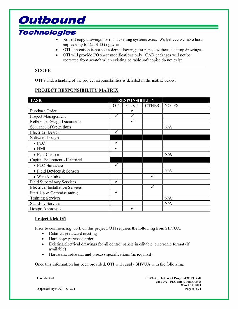
OTI’s understanding of the project responsibilities is detailed in the matrix below:
PROJECT RESPONSIBILITY MATRIX
TASK RESPONSIBILITY OTI CUST. OTHER NOTES Purchase Order Project Management Reference Design Documents Sequence of Operations N/A Electrical Design Software Design • PLC • HMI • PC / Custom N/A
Capital Equipment - Electrical • PLC Hardware • Field Devices & Sensors N/A • Wire & Cable
Field Supervisory Services Electrical Installation Services Start-Up & Commissioning Training Services N/A Stand-by Services N/A Design Approvals
Project Kick-Off
Prior to commencing work on this project, OTI requires the following from SHVUA: • Detailed pre-award meeting • Hard copy purchase order • Existing electrical drawings for all control panels in editable, electronic format (if
available) • Hardware, software, and process specifications (as required)
Once this information has been provided, OTI will supply SHVUA with the following:
Outbound Technologies
Confidential SHVUA – Outbound Proposal 20-P1176D
SHVUA – PLC Migration Project March 12, 2021
Approved By: CAJ – 3/12/21 Page 7 of 21
• Detailed schedule • Open issues list
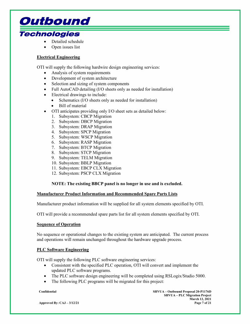
Electrical Engineering
OTI will supply the following hardwire design engineering services: • Analysis of system requirements • Development of system architecture • Selection and sizing of system components • Full AutoCAD detailing (I/O sheets only as needed for installation) • Electrical drawings to include:
• Schematics (I/O sheets only as needed for installation) • Bill of material
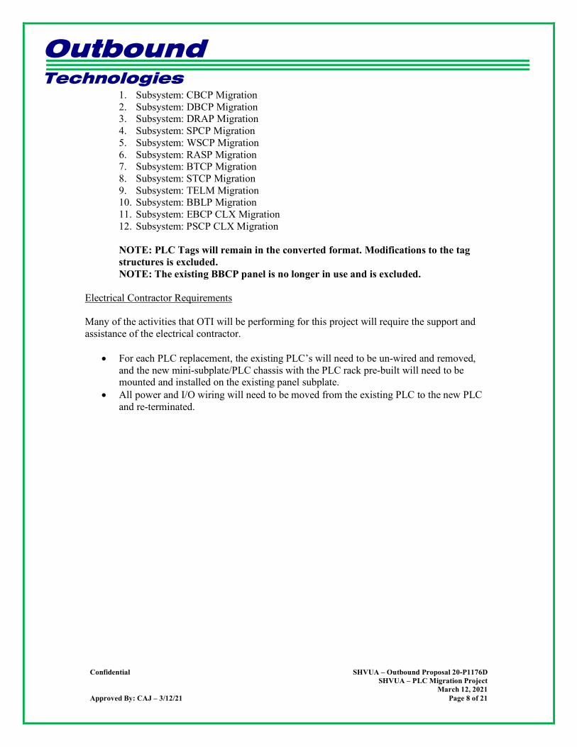
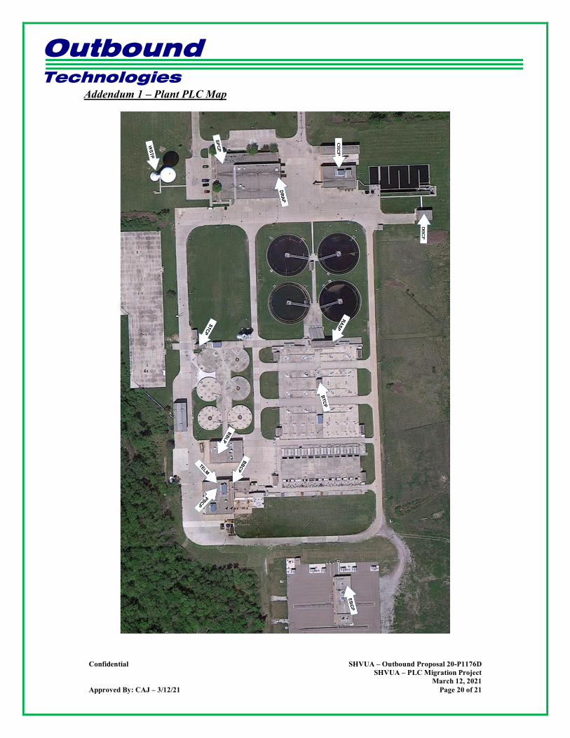
• OTI anticipates providing only I/O sheet sets as detailed below: 1. Subsystem: CBCP Migration 2. Subsystem: DBCP Migration 3. Subsystem: DRAP Migration 4. Subsystem: SPCP Migration 5. Subsystem: WSCP Migration 6. Subsystem: RASP Migration 7. Subsystem: BTCP Migration 8. Subsystem: STCP Migration 9. Subsystem: TELM Migration 10. Subsystem: BBLP Migration 11. Subsystem: EBCP CLX Migration 12. Subsystem: PSCP CLX Migration
NOTE: The existing BBCP panel is no longer in use and is excluded.
Manufacturer Product Information and Recommended Spare Parts Lists
Manufacturer product information will be supplied for all system elements specified by OTI. OTI will provide a recommended spare parts list for all system elements specified by OTI.
Sequence of Operation
No sequence or operational changes to the existing system are anticipated. The current process and operations will remain unchanged throughout the hardware upgrade process.
PLC Software Engineering
OTI will supply the following PLC software engineering services: • Consistent with the specified PLC operation, OTI will convert and implement the
updated PLC software programs. • The PLC software design engineering will be completed using RSLogix/Studio 5000. • The following PLC programs will be migrated for this project:
Outbound Technologies
Confidential SHVUA – Outbound Proposal 20-P1176D
SHVUA – PLC Migration Project March 12, 2021
Approved By: CAJ – 3/12/21 Page 8 of 21
1. Subsystem: CBCP Migration 2. Subsystem: DBCP Migration 3. Subsystem: DRAP Migration 4. Subsystem: SPCP Migration 5. Subsystem: WSCP Migration 6. Subsystem: RASP Migration 7. Subsystem: BTCP Migration 8. Subsystem: STCP Migration 9. Subsystem: TELM Migration 10. Subsystem: BBLP Migration 11. Subsystem: EBCP CLX Migration 12. Subsystem: PSCP CLX Migration
NOTE: PLC Tags will remain in the converted format. Modifications to the tag structures is excluded. NOTE: The existing BBCP panel is no longer in use and is excluded.
Electrical Contractor Requirements Many of the activities that OTI will be performing for this project will require the support and assistance of the electrical contractor.
• For each PLC replacement, the existing PLC’s will need to be un-wired and removed, and the new mini-subplate/PLC chassis with the PLC rack pre-built will need to be mounted and installed on the existing panel subplate.
• All power and I/O wiring will need to be moved from the existing PLC to the new PLC and re-terminated.

Outbound Technologies
Confidential SHVUA – Outbound Proposal 20-P1176D
SHVUA – PLC Migration Project March 12, 2021
Approved By: CAJ – 3/12/21 Page 9 of 21
Capital Equipment
OTI will supply the following capital equipment:
Qty Catalog # Description 3 1769-ECL Left End Cap Terminator 4 1769-L36ERM CompactLogix 5370 L3 Controller, 3Mb Memory w/Supercap Backup,
16 Axis CIP Motion, up to 30 1769 I/O expansion modules, 48 EtherNet/IP and 120 TCP connections
21 1769-IF4 4 Channel Analog Current/Voltage Input Module 17 1769-OF4 4 Channel Analog Current/Voltage Output Module 10 1769-PA4 120/240V AC Power Supply (5V @ 4 Amp) 32 1769-IA16 16 Point 120 VAC Input Module 3 1769-CRR1 Right bank-to-right bank expansion (305 mm) 31 1769-OA16 16 Point 120/240 AC Output Module 1 1769-IF8 8 Channel Analog Voltage/Current Input Module 7 1769-ECR Right End Cap Terminator 5 1769-L30ER CompactLogix 5370 L3 Controller, 2 EtherNet/IP ports, 1MB memory
w/ supercap backup, up to 8 1769 I/O expansion modules, 16 EtherNet/IP and 120 TCP connections
1 1769-IQ16 16 Point 24 VDC Sinking/Sourcing Input Module 3 1769-PA2 120/240V AC Power Supply (5V @ 2 Amp) 1 1769-L33ER CompactLogix 5370 L3 Controller, 2Mb Memory, w/Supercap Backup,
up to 16 1769 I/O expansion modules, 32 EtherNet/IP and 120 TCP connections
1 1769-IF4XOF2 4 In/2 Out Combo Analog Current/Voltage Module 2 1756-A17 1756 Chassis 17 slots 4 1756-PA75 85-265V AC Power Supply (5V @ 13 Amp) 3 1756-EN2TR EtherNet 10-100M Bridge Module (2-Ports) 2 1756-L71 Logix5671 Controller With 2 Mbytes Memory 15 1756-IA16 79-132 VAC Input 16 Pts (20 Pin) 26 1756-TBNH 20 Position NemA Screw Clamp Block 5 1756-OA16 74-265 VAC Output 16 Pts (20 Pin) 11 1756-OX8I N.O./N.C. Isolated Relay Output 8 Pts (36 Pin) 15 1756-TBCH 36 Pin Screw Clamp Block With Standard Housing 1 1756-A13 1756 Chassis 13 slots 6 1756-IF8 Analog Input - Current/Voltage 8 Pts (36 Pin) 3 1756-OF4 Analog Output - Current/Voltage 4 Pts (20 Pin) 1 1756-A7 1756 Chassis 7 slots 4 SMC1500C APC 1500VA 120VAC Uninterruptible Power Supply (UPS) 8 SMT2200C APC 2200VA 120VAC Uninterruptible Power Supply (UPS)
Outbound Technologies
Confidential SHVUA – Outbound Proposal 20-P1176D
SHVUA – PLC Migration Project March 12, 2021
Approved By: CAJ – 3/12/21 Page 10 of 21
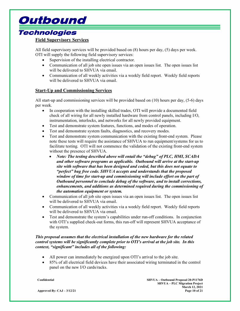
Field Supervisory Services
All field supervisory services will be provided based on (8) hours per day, (5) days per week. OTI will supply the following field supervisory services:
• Supervision of the installing electrical contractor. • Communication of all job site open issues via an open issues list. The open issues list
will be delivered to SHVUA via email. • Communication of all weekly activities via a weekly field report. Weekly field reports
will be delivered to SHVUA via email.
Start-Up and Commissioning Services
All start-up and commissioning services will be provided based on (10) hours per day, (5-6) days per week.
• In cooperation with the installing skilled trades, OTI will provide a documented field check of all wiring for all newly installed hardware from control panels, including I/O, instrumentation, interlocks, and networks for all newly provided equipment.
• Test and demonstrate system features, functions, and modes of operation. • Test and demonstrate system faults, diagnostics, and recovery modes. • Test and demonstrate system communication with the existing front-end system. Please
note these tests will require the assistance of SHVUA to run equipment/systems for us to facilitate testing. OTI will not commence the validation of the existing front-end system without the presence of SHVUA. • Note: The testing described above will entail the “debug” of PLC, HMI, SCADA
and other software programs as applicable. Outbound will arrive at the start-up site with software that has been designed and coded, but this does not equate to “perfect” bug free code. SHVUA accepts and understands that the proposed window of time for start-up and commissioning will include effort on the part of Outbound personnel to conclude debug of the software, and to install corrections, enhancements, and additions as determined required during the commissioning of the automation equipment or system.
• Communication of all job site open issues via an open issues list. The open issues list will be delivered to SHVUA via email.
• Communication of all weekly activities via a weekly field report. Weekly field reports will be delivered to SHVUA via email.
• Test and demonstrate the system’s capabilities under run-off conditions. In conjunction with OTI’s supplied check-out forms, this run-off will represent SHVUA acceptance of the system.
This proposal assumes that the electrical installation of the new hardware for the related control systems will be significantly complete prior to OTI’s arrival at the job site. In this context, “significant” includes all of the following:
• All power can immediately be energized upon OTI’s arrival to the job site. • 85% of all electrical field devices have their associated wiring terminated in the control
panel on the new I/O cards/racks.

Outbound Technologies
Confidential SHVUA – Outbound Proposal 20-P1176D
SHVUA – PLC Migration Project March 12, 2021
Approved By: CAJ – 3/12/21 Page 11 of 21
• All PLC communication wiring (i.e. Ethernet) has been completed between all control panels, VFDs, and peer-to-peer panels.
Additional compensation will be required in the event OTI arrives for commissioning without the above being complete.
Training Services
This proposal includes no formal training and no formal training activities. This service is not necessary as we are not altering the actual process or look and feel of the operator screens.
Stand-by Services
This proposal includes no standby time. This service is not necessary, and we can always use an existing blanket service contract for additional time if requested.
DOCUMENTATION
Project and Design Software Platforms
OTI will utilize the following software platforms for this project: Text, Spreadsheet, Reporting, and Project Planning
• Microsoft Word • Microsoft Excel
Electrical Design Drawings
• AutoCAD, version TBD
PLC Software Design • RSLogix/Studio 5000
Outbound Technologies
Confidential SHVUA – Outbound Proposal 20-P1176D
SHVUA – PLC Migration Project March 12, 2021
Approved By: CAJ – 3/12/21 Page 12 of 21
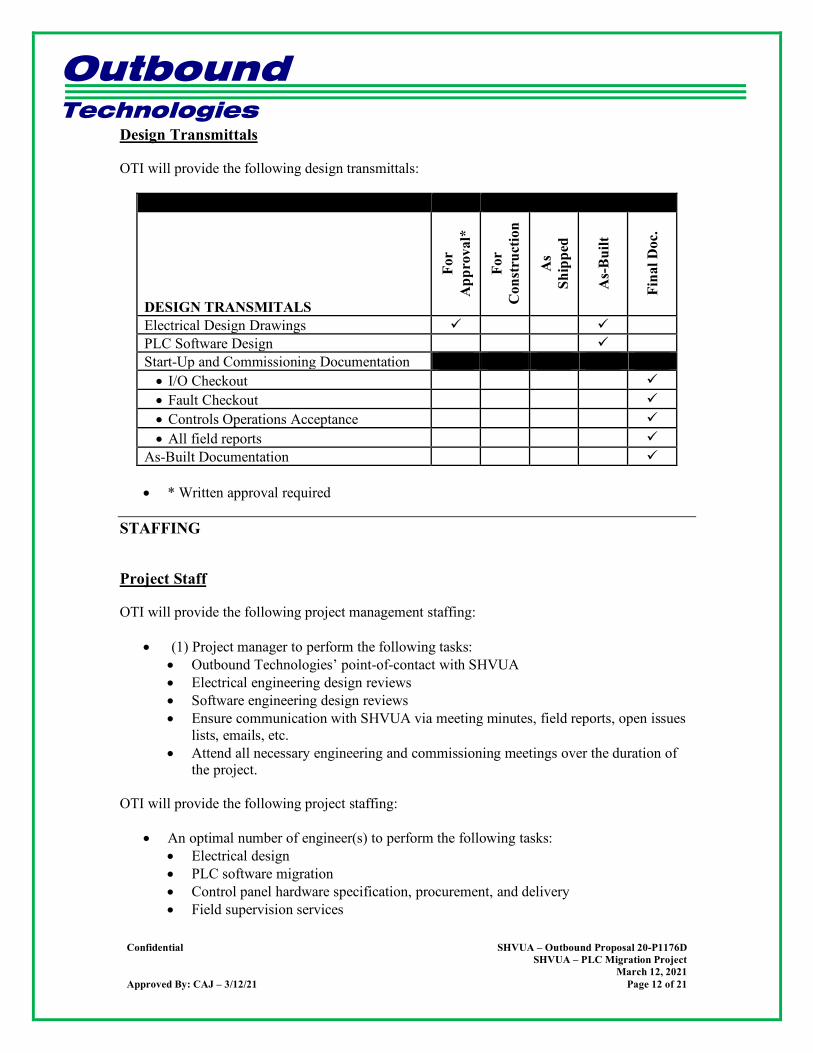
Design Transmittals
OTI will provide the following design transmittals:
DESIGN TRANSMITALS
For
App
rova
l*
For
Con
stru
ctio
n
As
Ship
ped
As-
Bui
lt
Fina
l Doc
.
Electrical Design Drawings PLC Software Design Start-Up and Commissioning Documentation • I/O Checkout • Fault Checkout • Controls Operations Acceptance • All field reports
As-Built Documentation
• * Written approval required
STAFFING
Project Staff
OTI will provide the following project management staffing:
• (1) Project manager to perform the following tasks: • Outbound Technologies’ point-of-contact with SHVUA • Electrical engineering design reviews • Software engineering design reviews • Ensure communication with SHVUA via meeting minutes, field reports, open issues
lists, emails, etc. • Attend all necessary engineering and commissioning meetings over the duration of
the project. OTI will provide the following project staffing:
• An optimal number of engineer(s) to perform the following tasks: • Electrical design • PLC software migration • Control panel hardware specification, procurement, and delivery • Field supervision services
Outbound Technologies
Confidential SHVUA – Outbound Proposal 20-P1176D
SHVUA – PLC Migration Project March 12, 2021
Approved By: CAJ – 3/12/21 Page 13 of 21
• Start-up and commissioning services • As-built documentation
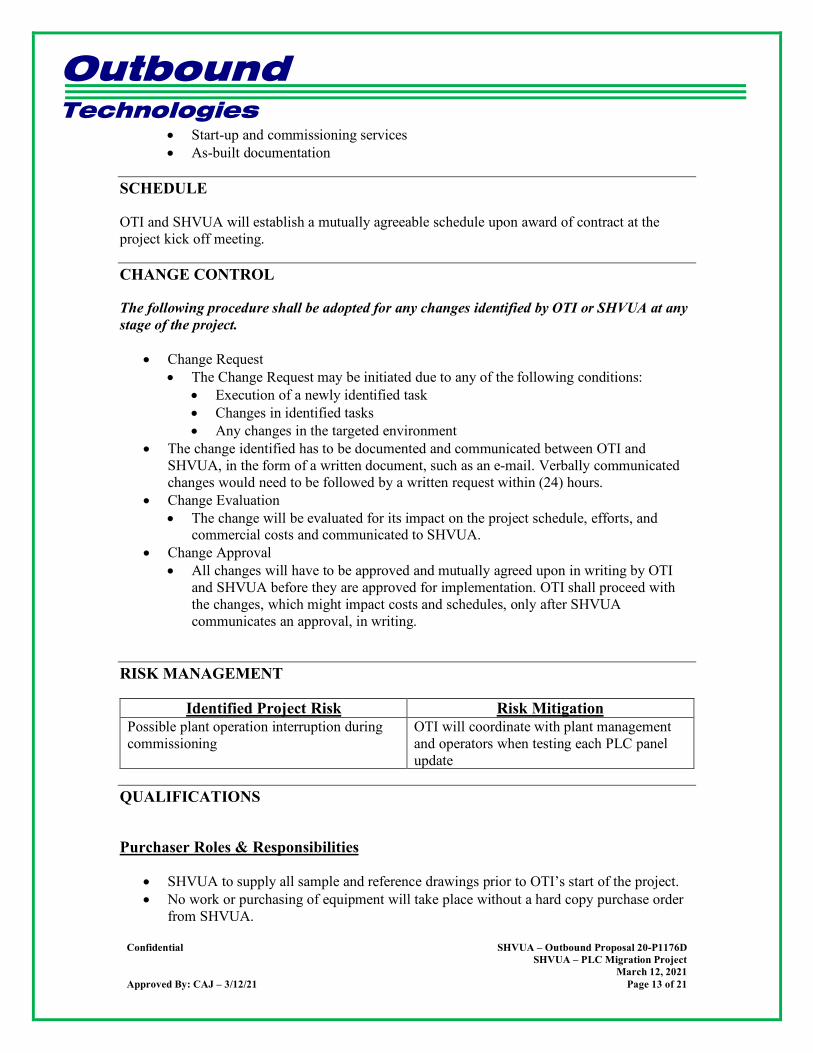
SCHEDULE
OTI and SHVUA will establish a mutually agreeable schedule upon award of contract at the project kick off meeting.
CHANGE CONTROL
The following procedure shall be adopted for any changes identified by OTI or SHVUA at any stage of the project.
• Change Request • The Change Request may be initiated due to any of the following conditions:
• Execution of a newly identified task • Changes in identified tasks • Any changes in the targeted environment
• The change identified has to be documented and communicated between OTI and SHVUA, in the form of a written document, such as an e-mail. Verbally communicated changes would need to be followed by a written request within (24) hours.
• Change Evaluation • The change will be evaluated for its impact on the project schedule, efforts, and
commercial costs and communicated to SHVUA. • Change Approval
• All changes will have to be approved and mutually agreed upon in writing by OTI and SHVUA before they are approved for implementation. OTI shall proceed with the changes, which might impact costs and schedules, only after SHVUA communicates an approval, in writing.
RISK MANAGEMENT
Identified Project Risk Risk Mitigation Possible plant operation interruption during commissioning
OTI will coordinate with plant management and operators when testing each PLC panel update
QUALIFICATIONS
Purchaser Roles & Responsibilities
• SHVUA to supply all sample and reference drawings prior to OTI’s start of the project. • No work or purchasing of equipment will take place without a hard copy purchase order
from SHVUA.

Outbound Technologies
Confidential SHVUA – Outbound Proposal 20-P1176D
SHVUA – PLC Migration Project March 12, 2021
Approved By: CAJ – 3/12/21 Page 14 of 21
• SHVUA to provide prompt review and approval of all design transmittals and documentation within the outline of the bid specifications. The basis for this proposal is OTI’s receipt of reviewed design submittals within ten (10) business days of transmittal. If design submittal comments are not received within this time period, OTI will inform SHVUA in writing that the project schedule is slipping day for day.
• OTI requires a detailed pre-award meeting between all the key OTI and SHVUA personnel prior to receipt of a purchase order.
• OTI requires that this proposal be referenced in SHVUA’s purchase order. • SHVUA to provide approved mechanical air flow and piping diagrams prior to OTI’s
start of electrical design engineering. • SHVUA to provide existing electrical drawings for all panels in editable, electronic
formal prior to OTI’s start of electrical design engineering. • SHVUA to provide the following:
• Any and all capital equipment and engineering services required, but not specifically listed in this proposal.
• Appropriate personnel to assist in the commissioning phase of the system. This includes operation of the equipment and installation, as required.
Commercial
• OTI will provide invoices with accurate and complete attachments to SHVUA’s Contracts Management once per month throughout the duration of the project.
• OTI’s price, schedule and deliverables are wholly and solely predicated on monthly, progress project invoices and the associated SHVUA progress payments.
• OTI’s price excludes minority content. • OTI’s price is in U.S. dollars. • Payment terms net (30) days after submittal of invoice. • This proposal is predicated on OTI’s ability to efficiently perform the project work, and
by issuing a purchase order SHVUA understands and accepts that OTI cannot be held liable for any unforeseen project and schedule delays due to restrictions put in place by federal or state governments due to the ongoing COVID-19 pandemic.
Capital Equipment
• OTI’s price is based on the specific manufacturers, part numbers, quantities, and sizes indicated in the “Capital Equipment” section of this proposal. OTI reserves the right to re-price based on any deviations from these items if price deviations are significant and unforeseen.
• This proposal excludes all material associated with the BBCP panel. • Material and equipment to be provided by others:
• All fire protection material • All conveyor control equipment • All field disconnect switches, bus plugs, and bus plug fuses. • All field wiring, including necessary quick-connect and communication cables. • All mounting brackets for field equipment.
Outbound Technologies
Confidential SHVUA – Outbound Proposal 20-P1176D
SHVUA – PLC Migration Project March 12, 2021
Approved By: CAJ – 3/12/21 Page 15 of 21
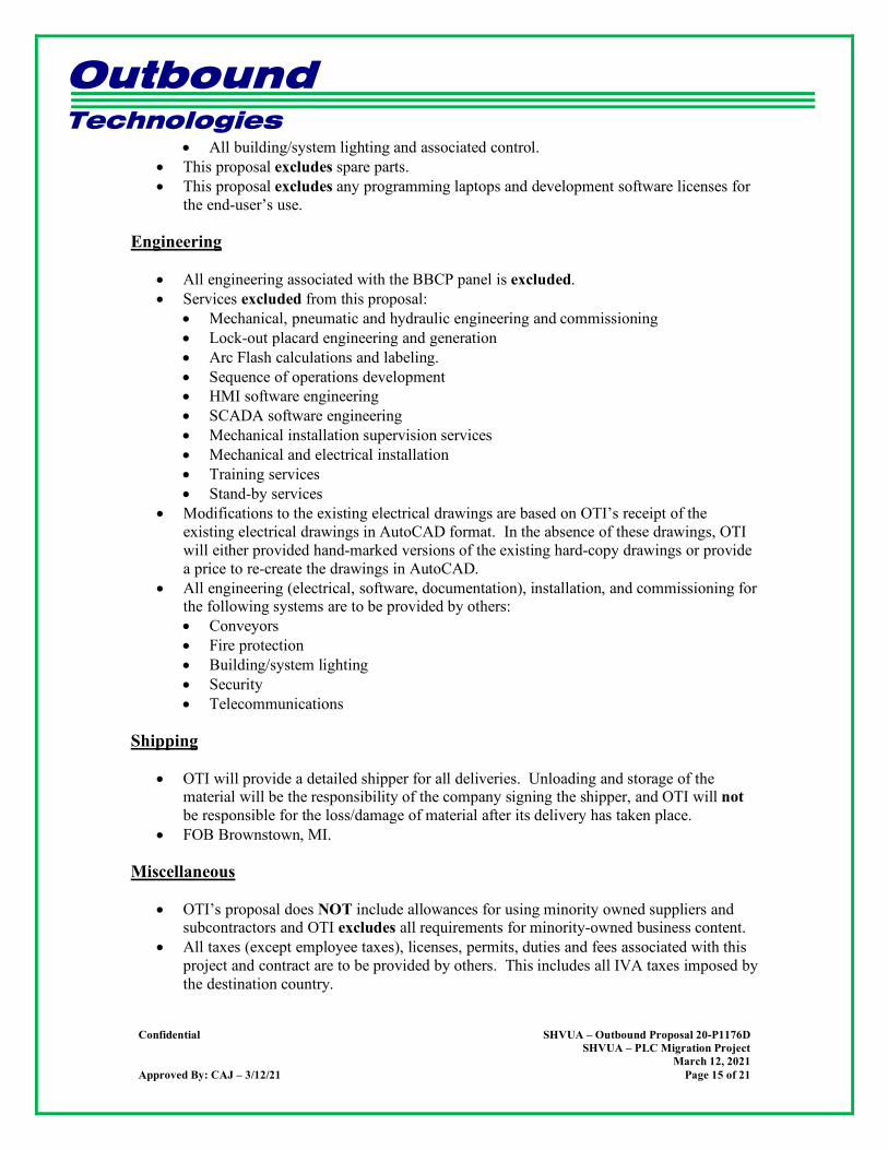
• All building/system lighting and associated control. • This proposal excludes spare parts. • This proposal excludes any programming laptops and development software licenses for
the end-user’s use.
Engineering
• All engineering associated with the BBCP panel is excluded. • Services excluded from this proposal:
• Mechanical, pneumatic and hydraulic engineering and commissioning • Lock-out placard engineering and generation • Arc Flash calculations and labeling. • Sequence of operations development • HMI software engineering • SCADA software engineering • Mechanical installation supervision services • Mechanical and electrical installation • Training services • Stand-by services
• Modifications to the existing electrical drawings are based on OTI’s receipt of the existing electrical drawings in AutoCAD format. In the absence of these drawings, OTI will either provided hand-marked versions of the existing hard-copy drawings or provide a price to re-create the drawings in AutoCAD.
• All engineering (electrical, software, documentation), installation, and commissioning for the following systems are to be provided by others: • Conveyors • Fire protection • Building/system lighting • Security • Telecommunications
Shipping
• OTI will provide a detailed shipper for all deliveries. Unloading and storage of the material will be the responsibility of the company signing the shipper, and OTI will not be responsible for the loss/damage of material after its delivery has taken place.
• FOB Brownstown, MI.
Miscellaneous
• OTI’s proposal does NOT include allowances for using minority owned suppliers and subcontractors and OTI excludes all requirements for minority-owned business content.
• All taxes (except employee taxes), licenses, permits, duties and fees associated with this project and contract are to be provided by others. This includes all IVA taxes imposed by the destination country.
Outbound Technologies
Confidential SHVUA – Outbound Proposal 20-P1176D
SHVUA – PLC Migration Project March 12, 2021
Approved By: CAJ – 3/12/21 Page 16 of 21
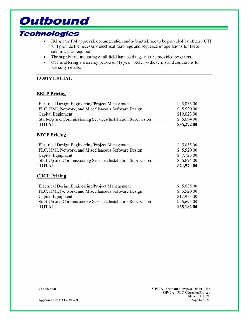
• IRI and/or FM approval, documentation and submittals are to be provided by others. OTI will provide the necessary electrical drawings and sequence of operations for these submittals as required.
• The supply and mounting of all field lamacoid tags is to be provided by others. • OTI is offering a warranty period of (1) year. Refer to the terms and conditions for
warranty details.
COMMERCIAL
BBLP Pricing
Electrical Design Engineering/Project Management $ 5,035.00 PLC, HMI, Network, and Miscellaneous Software Design $ 5,520.00 Capital Equipment $19,023.00 Start-Up and Commissioning Services/Installation Supervision $ 6,694.00 TOTAL $36,272.00
BTCP Pricing
Electrical Design Engineering/Project Management $ 5,035.00 PLC, HMI, Network, and Miscellaneous Software Design $ 5,520.00 Capital Equipment $ 7,725.00 Start-Up and Commissioning Services/Installation Supervision $ 6,694.00 TOTAL $24,974.00
CBCP Pricing
Electrical Design Engineering/Project Management $ 5,035.00 PLC, HMI, Network, and Miscellaneous Software Design $ 5,520.00 Capital Equipment $17,933.00 Start-Up and Commissioning Services/Installation Supervision $ 6,694.00 TOTAL $35,182.00
Outbound Technologies
Confidential SHVUA – Outbound Proposal 20-P1176D
SHVUA – PLC Migration Project March 12, 2021
Approved By: CAJ – 3/12/21 Page 17 of 21
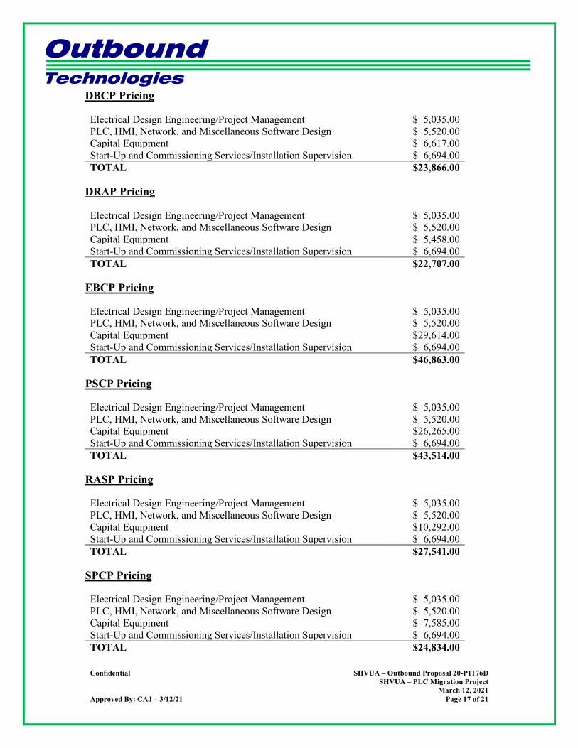
DBCP Pricing
Electrical Design Engineering/Project Management $ 5,035.00 PLC, HMI, Network, and Miscellaneous Software Design $ 5,520.00 Capital Equipment $ 6,617.00 Start-Up and Commissioning Services/Installation Supervision $ 6,694.00 TOTAL $23,866.00
DRAP Pricing
Electrical Design Engineering/Project Management $ 5,035.00 PLC, HMI, Network, and Miscellaneous Software Design $ 5,520.00 Capital Equipment $ 5,458.00 Start-Up and Commissioning Services/Installation Supervision $ 6,694.00 TOTAL $22,707.00
EBCP Pricing
Electrical Design Engineering/Project Management $ 5,035.00 PLC, HMI, Network, and Miscellaneous Software Design $ 5,520.00 Capital Equipment $29,614.00 Start-Up and Commissioning Services/Installation Supervision $ 6,694.00 TOTAL $46,863.00
PSCP Pricing
Electrical Design Engineering/Project Management $ 5,035.00 PLC, HMI, Network, and Miscellaneous Software Design $ 5,520.00 Capital Equipment $26,265.00 Start-Up and Commissioning Services/Installation Supervision $ 6,694.00 TOTAL $43,514.00
RASP Pricing
Electrical Design Engineering/Project Management $ 5,035.00 PLC, HMI, Network, and Miscellaneous Software Design $ 5,520.00 Capital Equipment $10,292.00 Start-Up and Commissioning Services/Installation Supervision $ 6,694.00 TOTAL $27,541.00
SPCP Pricing
Electrical Design Engineering/Project Management $ 5,035.00 PLC, HMI, Network, and Miscellaneous Software Design $ 5,520.00 Capital Equipment $ 7,585.00 Start-Up and Commissioning Services/Installation Supervision $ 6,694.00 TOTAL $24,834.00
Outbound Technologies
Confidential SHVUA – Outbound Proposal 20-P1176D
SHVUA – PLC Migration Project March 12, 2021
Approved By: CAJ – 3/12/21 Page 18 of 21
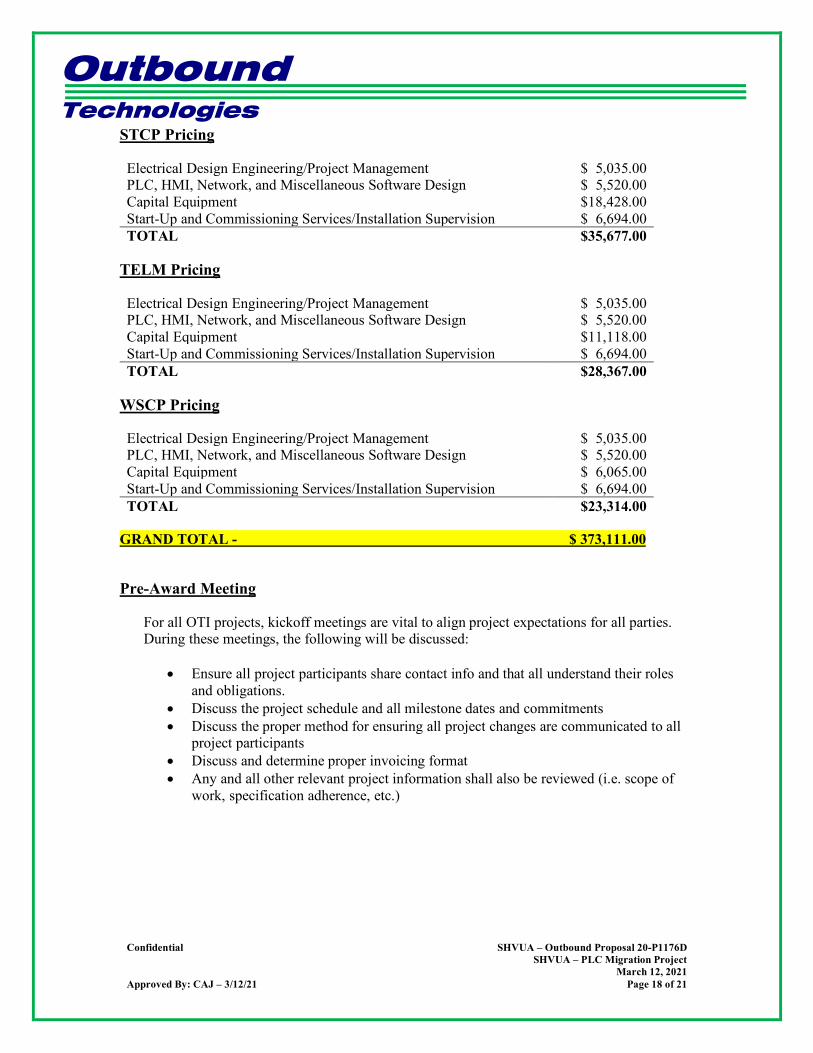
STCP Pricing
Electrical Design Engineering/Project Management $ 5,035.00 PLC, HMI, Network, and Miscellaneous Software Design $ 5,520.00 Capital Equipment $18,428.00 Start-Up and Commissioning Services/Installation Supervision $ 6,694.00 TOTAL $35,677.00
TELM Pricing
Electrical Design Engineering/Project Management $ 5,035.00 PLC, HMI, Network, and Miscellaneous Software Design $ 5,520.00 Capital Equipment $11,118.00 Start-Up and Commissioning Services/Installation Supervision $ 6,694.00 TOTAL $28,367.00
WSCP Pricing
Electrical Design Engineering/Project Management $ 5,035.00 PLC, HMI, Network, and Miscellaneous Software Design $ 5,520.00 Capital Equipment $ 6,065.00 Start-Up and Commissioning Services/Installation Supervision $ 6,694.00 TOTAL $23,314.00
GRAND TOTAL - $ 373,111.00
Pre-Award Meeting
For all OTI projects, kickoff meetings are vital to align project expectations for all parties. During these meetings, the following will be discussed:
• Ensure all project participants share contact info and that all understand their roles and obligations.
• Discuss the project schedule and all milestone dates and commitments • Discuss the proper method for ensuring all project changes are communicated to all
project participants • Discuss and determine proper invoicing format • Any and all other relevant project information shall also be reviewed (i.e. scope of
work, specification adherence, etc.)

Outbound Technologies
Confidential SHVUA – Outbound Proposal 20-P1176D
SHVUA – PLC Migration Project March 12, 2021
Approved By: CAJ – 3/12/21 Page 19 of 21
Terms & Conditions
Payment Terms: Contractual and payment terms will be negotiated with the project GC at the time of award of contract. Thank you very much for this opportunity. Sincerely, Chris Tury Jr. General Manager – Michigan Operations Outbound Technologies, Inc.
Attachment: Addendum 1 – Plant PLC Map Attachment: OTI’s Schedule of Fees
Outbound Technologies
Confidential SHVUA – Outbound Proposal 20-P1176D
SHVUA – PLC Migration Project March 12, 2021
Approved By: CAJ – 3/12/21 Page 20 of 21
Addendum 1 – Plant PLC Map
Outbound Technologies
Confidential SHVUA – Outbound Proposal 20-P1176D
SHVUA – PLC Migration Project March 12, 2021
Approved By: CAJ – 3/12/21 Page 21 of 21
`
SCHEDULE OF FEES
Contract Services Straight Time Over Time Premium Time Documentation Specialist $90.00/hour $103.50/hour $117.00/hour Controls Engineer – Tier 1 $90.00/hour $103.50/hour $117.00/hour Controls Engineer – Tier 2 $105.00/hour $121.00/hour $137.00/hour Controls Engineer – Tier 3 $115.00/hour $132.00/hour $150.00/hour Senior Engineer – Tier 1 $120.00/hour $138.00/hour $156.00/hour Senior Engineer – Tier 2 $125.00/hour $144.00/hour $163.00/hour Senior Engineer – Tier 3 $135.00/hour $155.00/hour $175.50/hour Assistant Engineering Manager $140.00/hour $160.00/hour $182.00/hour Engineering Manager $170.00/hour $195.50/hour $221.00/hour Engineering Director $200.00/hour $230.00/hour $260.00/hour
• Time Definition
• Straight Time: 1st (40) hours per week (excluding OTI holidays) • Over Time: Over (40) hours per week (excluding OTI holidays) • Premium Time: OTI holidays
• Travel Time: To and from job site, billed per straight time. • Minimum Billing: (4) hours daily plus travel time • Expenses
o Travel & lodging billed at cost plus 10% gross margin. o Use of personal vehicles billed at IRS Rates plus 10% gross margin. o $60.00 per diem billed for meals, telephone allowance, miscellaneous. o Material and subcontracts will be billed at cost plus 10% gross margin.
• Visits home o For out-of-town services, Outbound policy requires a trip home every (2) weeks: (3) days
of (14) to return home and return to the job site. o Visits home for international travel negotiated at time of order.
• Terms o Invoicing occurs every (2) weeks. o Payment net (30) days from date of invoice. o There will be no retention money withheld or back-charges applied associated with supplied
hourly services. o By purchasing hourly services, the customer understands that Outbound personnel are being
directed and supervised by the customer, daily or weekly. • In purchasing hourly services, customer agrees to provide signature approval to a daily or
weekly Outbound Field Report, regardless of where services are performed, said approval representing approval and acceptance of services for billing purposes.
o Outbound personnel will leave the jobsite prior to the Not To Exceed amount being reached. Adequate forewarning to the customer will be provided on a timely manner for the processing of an addendum by the customer to avoid any delay in project schedule.
o All time and material service requests must be in writing with a formal purchase order or letter of intent, with a Not To Exceed dollar amount.
o In the issuing of a Purchase Order per this Schedule, Customer agrees not to solicit OTI’s employees for hire.
o Warranty items for hourly services (time-and-materials) will be agreed upon during receipt of order. In the absence of this agreement, OTI provides no warranty for hourly services.
o OTI reserves the right to implement an annual rate increase.

SOUTH HURON VALLEY UTILLITY AUTHORITY SHVUE PRIORITY 1 AND 2 IMPROVEMENTS PROJECT
Hubbell, Roth & Clark, Inc. Job 20190897
APPENDIX D
Metering Instrumentation
Outbound Technologies
30026 Research Drive New Hudson, Michigan 48165 (248) 735-5000 (248) 735-5001 Fax
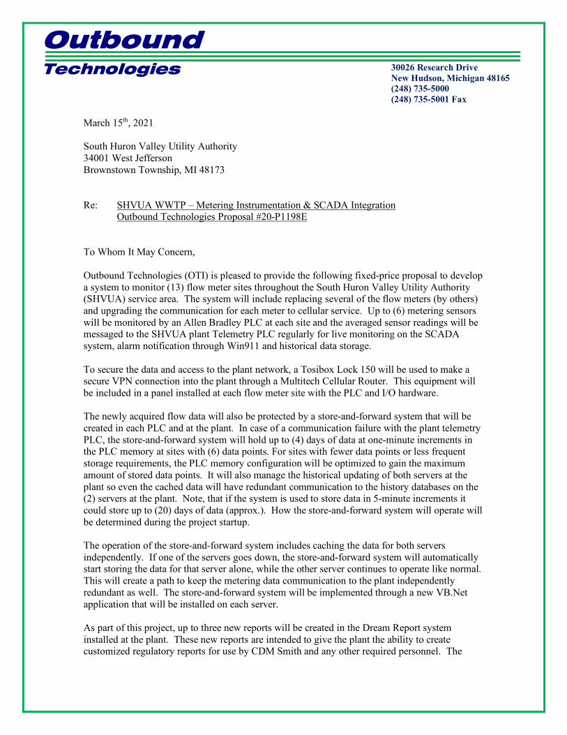
March 15th, 2021 South Huron Valley Utility Authority 34001 West Jefferson Brownstown Township, MI 48173 Re: SHVUA WWTP – Metering Instrumentation & SCADA Integration
Outbound Technologies Proposal #20-P1198E To Whom It May Concern, Outbound Technologies (OTI) is pleased to provide the following fixed-price proposal to develop a system to monitor (13) flow meter sites throughout the South Huron Valley Utility Authority (SHVUA) service area. The system will include replacing several of the flow meters (by others) and upgrading the communication for each meter to cellular service. Up to (6) metering sensors will be monitored by an Allen Bradley PLC at each site and the averaged sensor readings will be messaged to the SHVUA plant Telemetry PLC regularly for live monitoring on the SCADA system, alarm notification through Win911 and historical data storage. To secure the data and access to the plant network, a Tosibox Lock 150 will be used to make a secure VPN connection into the plant through a Multitech Cellular Router. This equipment will be included in a panel installed at each flow meter site with the PLC and I/O hardware. The newly acquired flow data will also be protected by a store-and-forward system that will be created in each PLC and at the plant. In case of a communication failure with the plant telemetry PLC, the store-and-forward system will hold up to (4) days of data at one-minute increments in the PLC memory at sites with (6) data points. For sites with fewer data points or less frequent storage requirements, the PLC memory configuration will be optimized to gain the maximum amount of stored data points. It will also manage the historical updating of both servers at the plant so even the cached data will have redundant communication to the history databases on the (2) servers at the plant. Note, that if the system is used to store data in 5-minute increments it could store up to (20) days of data (approx.). How the store-and-forward system will operate will be determined during the project startup. The operation of the store-and-forward system includes caching the data for both servers independently. If one of the servers goes down, the store-and-forward system will automatically start storing the data for that server alone, while the other server continues to operate like normal. This will create a path to keep the metering data communication to the plant independently redundant as well. The store-and-forward system will be implemented through a new VB.Net application that will be installed on each server. As part of this project, up to three new reports will be created in the Dream Report system installed at the plant. These new reports are intended to give the plant the ability to create customized regulatory reports for use by CDM Smith and any other required personnel. The

Outbound Technologies
Confidential GC – Outbound Proposal 20-P1198E SHVUA WWTP - Metering Instrumentation & SCADA Integration
March 15, 2021 Approved By: CAJ – 3/12/21 Page 2 of 6
system will have the capability for the users to view data ad hoc on a historical trend plot and then export that data as desired to a CSV file if desired. The reports can be created in PDF, CSV, HTML, Excel, and other formats. They can also be configured to be emailed to any required users when complete. OTI will also provide (2) Tosibox USB keys for remote access to the plant reporting server so custom reports can be run as needed. Each site has a flow meter model that was selected to optimize the operation at that site, so all of the meters are not the same. The communication between the PLC at each site with its flow meter will be implemented according to the following schedule: Total Storage Comm. Location Sensors Sensor Data Frequency Type
SH-1 1 Flow 1 Min 4-20ma Input SH-2 6 Flow, Depth, Velocity (2 each) 5 Min Modbus SH-3 6 Flow, Depth, Velocity (2 each) 5 Min Modbus SH-4 6 Flow, Depth, Velocity (2 each) 5 Min Modbus SH-5 6 Flow, Depth, Velocity (2 each) 5 Min Modbus SH-6 4 Flow, Depth, Secondary Depth, Velocity 5 Min Modbus SH-7 1 Flow 1 Min 4-20ma Input SH-8 5 Flow, Primary Depth, Level 1&2 Depth,
Velocity 5 Min Modbus
SH-10 1 Flow 5 Min 4-20ma Input SH-12 1 Flow 1 Min 4-20ma Input SH-14 4 Flow, Depth, Secondary Depth, Velocity 5 Min Modbus SH-16 6 Flow, Depth, Velocity (2 each) 5 Min Modbus SH-17 6 Flow, Depth, Velocity (2 each) 5 Min Modbus
Please note that OTI is excluding any hardware, software, or modifications to the metering equipment to support the communication described above. Electrical Engineering: OTI will provide the following electrical engineering services:
• Analysis of system requirements • Development of system architecture • Selection and sizing of system components • Full AutoCAD detailing • OTI anticipates providing drawing packages as detailed below:
• (13) Wireless data collection metering control panel(s) Software Engineering: OTI will provide the following software engineering services:
• Create a new FactoryTalk View screen with a service area map and live flow readings.

Outbound Technologies
Confidential GC – Outbound Proposal 20-P1198E SHVUA WWTP - Metering Instrumentation & SCADA Integration
March 15, 2021 Approved By: CAJ – 3/12/21 Page 3 of 6
• Add the new tags to the FactoryTalk Datalogger for historical data storage and retrieval through trending.
• Add alarms for the new tags to Win911 so plant personnel will be notified if any of the flow readings are above a configurable setpoint.
• VB.Net programming to create the store-and-forward application that will run on each of the plant process data servers. This programming will automatically recover from a communication loss and retrieve the data.
• VB.Net programming to retrieve the flow meter and rain gauge data from the FactoryTalk View SE Datalog database.
• VB.Net programming to create the new CSV data files as required. • PLC programming for all (13) flow metering PLCs and the plant Telemetry PLC. • PLC programming to implement the store and forward data management system in all
(13) metering PLCs. • Configuration and testing of the Tosibox lock and VPN connections. • Up to three (3) reports will be created in the plant Dream Report system for automated
and/or ad hoc flow data reporting. In addition, an ad hoc trending and exporting tool is included.
Material and Panel-Build: OTI will provide the material and build labor per the matrix below:
Metering Control Panel Quantity Description
13 Custom unit, including the following features: • Custom NEMA 4X, wall mount, stainless steel enclosure, clamp fastened
door (approx. 24”H x 20”W x 8”D) • 120VAC to 24VDC, 5 Amp power supply • Allen Bradley CompactLogix PLC (5069-L306ER) and Analog input
modules (as required) • Tosibox 150 industrial remote access router • Multitech cellular modem with sim card • RTA Modbus RTU to Ethernet/IP gateway (as required) • PULS 24vdc DIN Rail UPS (UB10.241) • Panel fan heater with thermostat • Din rail-mounted single 120VAC outlet • Omni directional antenna and mounting hardware • As required all necessary, circuit protection, terminals, and wire-way
2 Tosibox Key 200 Field Engineering:
• Coordinate with Teledyne, Hesco and plant personnel to configure all security and database communication required for the project.
• Commission the new VB.Net software on the FactoryTalk View Servers. • Validation of all programming included in the “Software Engineering” section of this
proposal.
Outbound Technologies
Confidential GC – Outbound Proposal 20-P1198E SHVUA WWTP - Metering Instrumentation & SCADA Integration
March 15, 2021 Approved By: CAJ – 3/12/21 Page 4 of 6
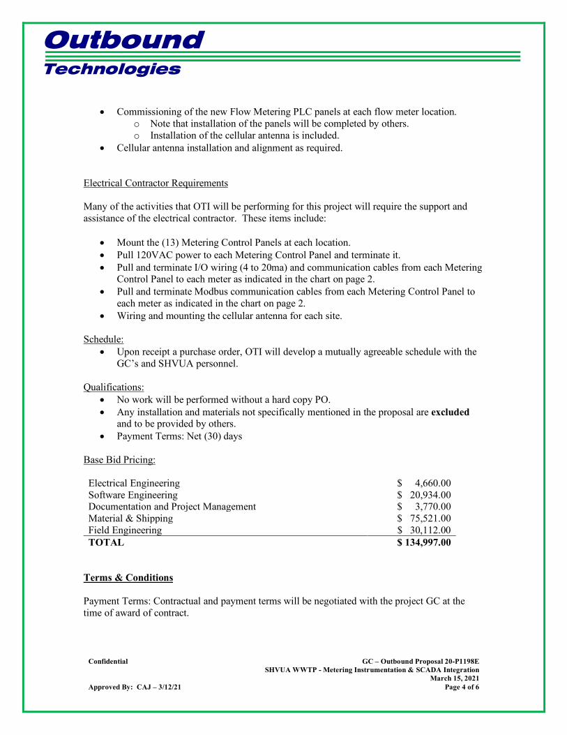
• Commissioning of the new Flow Metering PLC panels at each flow meter location. o Note that installation of the panels will be completed by others. o Installation of the cellular antenna is included.
• Cellular antenna installation and alignment as required.
Electrical Contractor Requirements Many of the activities that OTI will be performing for this project will require the support and assistance of the electrical contractor. These items include:
• Mount the (13) Metering Control Panels at each location. • Pull 120VAC power to each Metering Control Panel and terminate it. • Pull and terminate I/O wiring (4 to 20ma) and communication cables from each Metering
Control Panel to each meter as indicated in the chart on page 2. • Pull and terminate Modbus communication cables from each Metering Control Panel to
each meter as indicated in the chart on page 2. • Wiring and mounting the cellular antenna for each site.
Schedule:
• Upon receipt a purchase order, OTI will develop a mutually agreeable schedule with the GC’s and SHVUA personnel.
Qualifications: • No work will be performed without a hard copy PO. • Any installation and materials not specifically mentioned in the proposal are excluded
and to be provided by others. • Payment Terms: Net (30) days
Base Bid Pricing: Electrical Engineering $ 4,660.00 Software Engineering $ 20,934.00 Documentation and Project Management $ 3,770.00 Material & Shipping $ 75,521.00 Field Engineering $ 30,112.00 TOTAL $ 134,997.00
Terms & Conditions Payment Terms: Contractual and payment terms will be negotiated with the project GC at the time of award of contract.

Outbound Technologies
Confidential GC – Outbound Proposal 20-P1198E SHVUA WWTP - Metering Instrumentation & SCADA Integration
March 15, 2021 Approved By: CAJ – 3/12/21 Page 5 of 6
We appreciate this opportunity to support the authority and look forward to our continued relationship. Best Regards, Chris Tury Jr. General Manager – Michigan Operations Outbound Technologies Inc.
Attachments: OTI Schedule of Fees
Outbound Technologies
Confidential GC – Outbound Proposal 20-P1198E SHVUA WWTP - Metering Instrumentation & SCADA Integration
March 15, 2021 Approved By: CAJ – 3/12/21 Page 6 of 6
SCHEDULE OF FEES
Contract Services Straight Time Over Time Premium Time Documentation Specialist $90.00/hour $103.50/hour $117.00/hour Controls Engineer – Tier 1 $90.00/hour $103.50/hour $117.00/hour Controls Engineer – Tier 2 $105.00/hour $121.00/hour $137.00/hour Controls Engineer – Tier 3 $115.00/hour $132.00/hour $150.00/hour Senior Engineer – Tier 1 $120.00/hour $138.00/hour $156.00/hour Senior Engineer – Tier 2 $125.00/hour $144.00/hour $163.00/hour Senior Engineer – Tier 3 $135.00/hour $155.00/hour $175.50/hour Assistant Engineering Manager $140.00/hour $160.00/hour $182.00/hour Engineering Manager $170.00/hour $195.50/hour $221.00/hour Engineering Director $200.00/hour $230.00/hour $260.00/hour
• Time Definition o Straight Time: 1st (40) hours per week (excluding OTI holidays) o Over Time: Over (40) hours per week (excluding OTI holidays) o Premium Time: OTI holidays
• Travel Time: To and from job site, billed per above rates • Minimum Billing: (4) hours daily plus travel time • Expenses
o Travel & lodging billed at cost plus 10% gross margin o Use of personal vehicles billed at IRS Rates plus 10% gross margin o $60.00 per diem billed for meals, telephone allowance, miscellaneous o Material and subcontracts will be billed at cost plus 10% gross margin
• Visits home o For out of town services, Outbound policy requires a trip home every (2) weeks: (3) days
of (14) to return home and return to the job site. o Visits home for international travel negotiated at time of order.
• Terms o Invoicing occurs every (2) weeks o Payment net (30) days from date of invoice. o There will be no retention money withheld or back-charges applied associated with
supplied hourly services o By purchasing hourly services, the customer understands that Outbound personnel are
being directed and supervised by the customer, daily or weekly. • In purchasing hourly services, customer agrees to provide signature approval to a
daily or weekly Outbound Field Report, regardless of where services are performed, said approval representing approval and acceptance of services for billing purposes.
o Outbound personnel will leave the jobsite prior to the Not To Exceed amount being reached. Adequate forewarning to the customer will be provided on a timely manner for the processing of an addendum by the customer to avoid any delay in project schedule.
o All time and material service requests must be in writing with a formal purchase order or letter of intent, with a Not To Exceed dollar amount.
o In the issuing of a Purchase Order per this Schedule, Customer agrees not to solicit OTI’s employees for hire.
o Warranty items for hourly services (time-and-materials) will be agreed upon during receipt of order. In the absence of this agreement, OTI provides no warranty for hourly services.

SOUTH HURON VALLEY UTILLITY AUTHORITY SHVUE PRIORITY 1 AND 2 IMPROVEMENTS PROJECT
Hubbell, Roth & Clark, Inc. Job 20190897
APPENDIX E
Priority 1 and 2 Controls
Outbound Technologies
30026 Research Drive New Hudson, Michigan 48165 (248) 735-5000 (248) 735-5001 Fax
March 15th, 2021 South Huron Valley Utility Authority 34001 West Jefferson Brownstown Township, MI 48173 Re: SHVUA – Priority 1 & 2 Improvements Project
Outbound Technologies Proposal #21-P1018D To Whom It May Concern, Outbound Technologies is pleased to offer the following fixed-price proposal for the controls portion of the Priority 1 & 2 Improvements Project at South Huron Valley Utility Authority’s (SHVUA) facility in Brownstown, MI. Please note that this proposal is addressed to SHVUA, but the project will be executed with Outbound completing the scope of this proposal under the GC’s contract. Any reference to SHVUA in the body of the proposal below implies that OTI is also referencing the GC as the contracted representative for SHVUA. General Scope: OTI will provide controls software development, capital equipment procurement (as listed below) and commissioning for:
• (1) New Mixed Liquor Suspended Solids Control Panel (MLSSCP): o (1) New process control PLC program per spec 16950, (P) 2.6 o (1) New Panelview HMI application o Required control & monitoring SCADA integration. o The MLSSCP control panel is not included in this proposal. It will be put out to
bid separately in the bid pack. o Note: Panelview hardware is not included in this proposal; only software
engineering. • (2) Grit Systems
o Grit System HMI to be supplied by Grit System vendor as part of a package. o SCADA status and control integration to match the vendor-supplied HMI
functionality by importing their FactoryTalk View screens. • Pump Station Control Panel (PSCP):
o (1) Diversion Slide Gate (PLC control modifications and SCADA integration) o (1) Pump Station Stand-by Generator (SCADA integration only) o (4) PLC and SCADA updates to monitor and control the new VFDs for primary
influent pumps P2, P3, P4 and P6 • RAS Panel Modifications (PLC control modifications and SCADA integration):
o (1) RAS Pump VFD o (4) Final Clarifier Isolation Gates o (1) Final Clarifier Control Panel (FCCP) Communication (SCADA integration
only)

Outbound Technologies
Confidential Outbound Proposal 21-P1018D SHVUA - Priority 1 & 2 Improvements Project
March 12, 2021 Approved By: CAJ – 3/12/21 Page 2 of 7
• Final Clarifier Control Panel (SCADA integration only): o Control panel will be supplied by separate vendor as a package. o SCADA will provide four status inputs and one run signal output through hard
wired output to the vendor supplied panel for each of the (4) final clarifiers. o SCADA will display required data per section 16950 section 2.12 of the spec.
• Chemical Building Control panel (CBCP): o (3) SFE Pump VFDs (PLC control modifications and SCADA integration) o (3) SFE Filter Control Panels (PLC control modifications and SCADA
integration) o (1) SFE flow meter input integration (PLC control and SCADA integration) o (1) New Differential pressure sensor integration (SCADA integration only) o (1) Chemical Building Stand-by Generator (SCADA integration only)
• Sludge Thickening Control Panel (STCP): o (1) Flow Meter (SCADA integration only)
• Lystek Facility Control Panel (LFCP): o Monitor required data from LFCP (SCADA integration only) o SCADA status and control integration to match the Lystek system vendor
supplied HMI functionality by importing their FactoryTalk View screens. • Odette Pumping Station Control Panel I/O additions (PLC control modifications and
SCADA integration): o Generator Fault o Valve Vault Flooded o Intrusion Alarm o High Float Switch out of normal o Low Float Switch out of normal
• Trenton Arm Pumping Station (TAPS CP): o (1) Security Gate (PLC control modifications and SCADA integration)
Electrical Engineering: OTI will supply the following electrical engineering services:
• OTI will provide the necessary electrical engineering and AutoCAD detailing to modify the existing electrical drawings to reflect the additions of any new I/O cards procured by OTI as part of our scope on this project.
• OTI will only provide AutoCAD drawings under the assumption that AutoCAD files of the existing electrical drawings are available. In the absence of these AutoCAD files, OTI will provide red-line mark-ups of PDF or hard copy drawings that may be available.
Software Engineering: OTI will supply the following software engineering services:
• Consistent with the specified PLC operation, OTI will design and implement the PLC software programs.
• Consistent with the specified HMI operation, OTI will design and implement the operator interface.
• Consistent with the specified SCADA operation, OTI will modify the existing SCADA application to include the new and/or modified systems.
• The PLC software engineering will be completed using Studio 5000 Logix Designer.
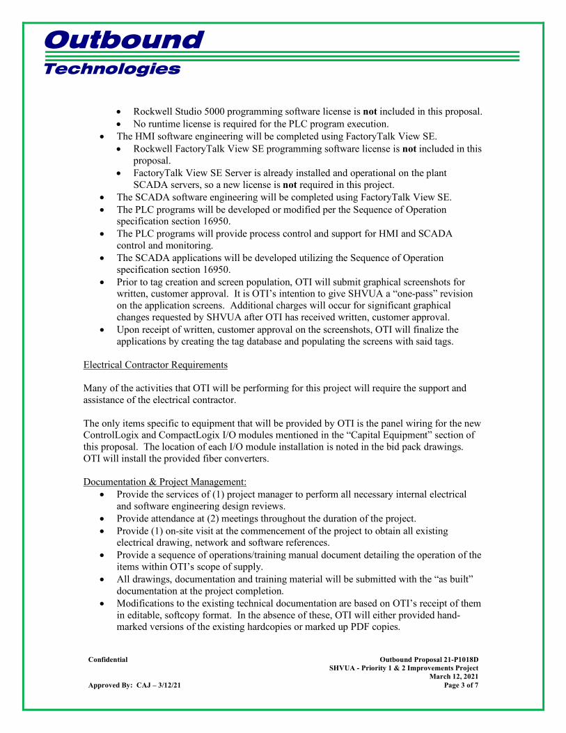
Outbound Technologies
Confidential Outbound Proposal 21-P1018D SHVUA - Priority 1 & 2 Improvements Project
March 12, 2021 Approved By: CAJ – 3/12/21 Page 3 of 7
• Rockwell Studio 5000 programming software license is not included in this proposal. • No runtime license is required for the PLC program execution.
• The HMI software engineering will be completed using FactoryTalk View SE. • Rockwell FactoryTalk View SE programming software license is not included in this
proposal. • FactoryTalk View SE Server is already installed and operational on the plant
SCADA servers, so a new license is not required in this project. • The SCADA software engineering will be completed using FactoryTalk View SE. • The PLC programs will be developed or modified per the Sequence of Operation
specification section 16950. • The PLC programs will provide process control and support for HMI and SCADA
control and monitoring. • The SCADA applications will be developed utilizing the Sequence of Operation
specification section 16950. • Prior to tag creation and screen population, OTI will submit graphical screenshots for
written, customer approval. It is OTI’s intention to give SHVUA a “one-pass” revision on the application screens. Additional charges will occur for significant graphical changes requested by SHVUA after OTI has received written, customer approval.
• Upon receipt of written, customer approval on the screenshots, OTI will finalize the applications by creating the tag database and populating the screens with said tags.
Electrical Contractor Requirements Many of the activities that OTI will be performing for this project will require the support and assistance of the electrical contractor. The only items specific to equipment that will be provided by OTI is the panel wiring for the new ControlLogix and CompactLogix I/O modules mentioned in the “Capital Equipment” section of this proposal. The location of each I/O module installation is noted in the bid pack drawings. OTI will install the provided fiber converters. Documentation & Project Management:
• Provide the services of (1) project manager to perform all necessary internal electrical and software engineering design reviews.
• Provide attendance at (2) meetings throughout the duration of the project. • Provide (1) on-site visit at the commencement of the project to obtain all existing
electrical drawing, network and software references. • Provide a sequence of operations/training manual document detailing the operation of the
items within OTI’s scope of supply. • All drawings, documentation and training material will be submitted with the “as built”
documentation at the project completion. • Modifications to the existing technical documentation are based on OTI’s receipt of them
in editable, softcopy format. In the absence of these, OTI will either provided hand-marked versions of the existing hardcopies or marked up PDF copies.

Outbound Technologies
Confidential Outbound Proposal 21-P1018D SHVUA - Priority 1 & 2 Improvements Project
March 12, 2021 Approved By: CAJ – 3/12/21 Page 4 of 7
Capital Equipment: • (6) StarTech 10/100MB Fiber Converters • (1) ControlLogix 8 Channel Analog Input Module 1756-IF8 (PSCP) • (1) ControlLogix 16 Channel Discrete Input Module 1756-IA16 (PSCP) • (1) CompactLogix 8 Channel Analog Input Module 1769-IF8 (CBCP) • (1) CompactLogix 4 Channel Analog Output Module 1769-OF4 (CBCP • (2) CompactLogix 16 Point 120 VAC Input Module 1769-IA16 (RASPx2) • (1) CompactLogix 16 Point 120 VAC Output Module 1769-OA16 (RASP)
Startup and Commissioning: All start-up and commissioning services will be provided based on (10) hours per day, (5) days per week. OTI will supply the following start-up and commissioning services:
• Test and demonstrate system features, functions, and modes of operation. • Test and demonstrate system faults, diagnostics, and recovery modes. • Test and demonstrate the system’s capabilities under run-off conditions. In conjunction
with OTI’s supplied check-out forms, this run-off will represent SHVUA’s acceptance of the system.
This proposal assumes that the mechanical and electrical installation of the process and related control systems will be 100% complete prior to OTI’s arrival at the job site. In this context, “complete” includes all of the following:
• All power wiring terminated in the panels and in the field. This includes control panels,
bus ducts/plugs, power distribution panels, motor control centers, and motors. • Power can immediately be energized upon OTI’s arrival to the job site. • 85% of all electrical field devices have their associated wiring terminated in the control
panel and in the field. • All interlock wiring has been completed between the Remote Panels, fire protection
panels, VFD/soft start/combination starter panels and E-Stop Interlock Control Panel. • All PLC communication wiring (i.e., Ethernet) has been completed between all control
panels, VFDs, and peer-to-peer panels. • All Process piping is 100% complete, including connections to the main plant headers. • Piping work is complete to the point at which all motors can be operated, and all valves
can be actuated, with no risk to personnel safety. • All utility piping is complete (includes compressed air and fresh water supply). • System has been pre-charged (filled) with water and any chemical solutions that are
required to fully test the proper function of each system. • OTI will provide any onsite support as needed for any systems that must be hot swapped
and would require a programmer onsite to restore said systems.

Outbound Technologies
Confidential Outbound Proposal 21-P1018D SHVUA - Priority 1 & 2 Improvements Project
March 12, 2021 Approved By: CAJ – 3/12/21 Page 5 of 7
Additional compensation will be required in the event OTI arrives for commissioning without the above being complete. Additionally, supervision of the installing electrical contractor is not included in this proposal and OTI’s commissioning time is not allotted for this use. Training: All training services will be provided based on (2) 8-hour classes, with each class including the following:
• Systems operation training for operators • Software design & function for maintenance personnel
Training services required beyond this quoted timeframe due to circumstances outside of OTI’s control will be provided based on OTI’s standard Schedule of Fees. OTI will supply the following training services:
• For each training session, OTI will provide one (1) Operations Manual for each student. • Training time will be divided evenly between classroom instruction and hands-on
examples. • Classroom instruction will focus on the Operations Manual. System specifics, automatic
and manual modes, faults, recovery, and HMI and SCADA operations will be the primary focus.
• The hands-on training will focus on trouble-shooting examples, system operation via the HMI, automatic start and stop of the system, manual start and stop of the system, and fault recovery options.
Schedule: The schedule is as follows:
• OTI and GC will establish a mutually agreeable schedule upon award of contract at the project kick off meeting.
Qualifications:
• All capital equipment and material not listed in this proposal is excluded and to be provided by others.
• Services excluded from this proposal: • Mechanical, pneumatic, and hydraulic engineering and commissioning • Manufacturer’s literature compilation • Recommended spare parts list generation • Lock-out placard engineering and generation • Arc Flash calculations and labeling • Mechanical and electrical installation supervision services • Mechanical and electrical installation • Stand-by services
• No work will be performed without a hard copy PO. • FOB Brownstown, MI.
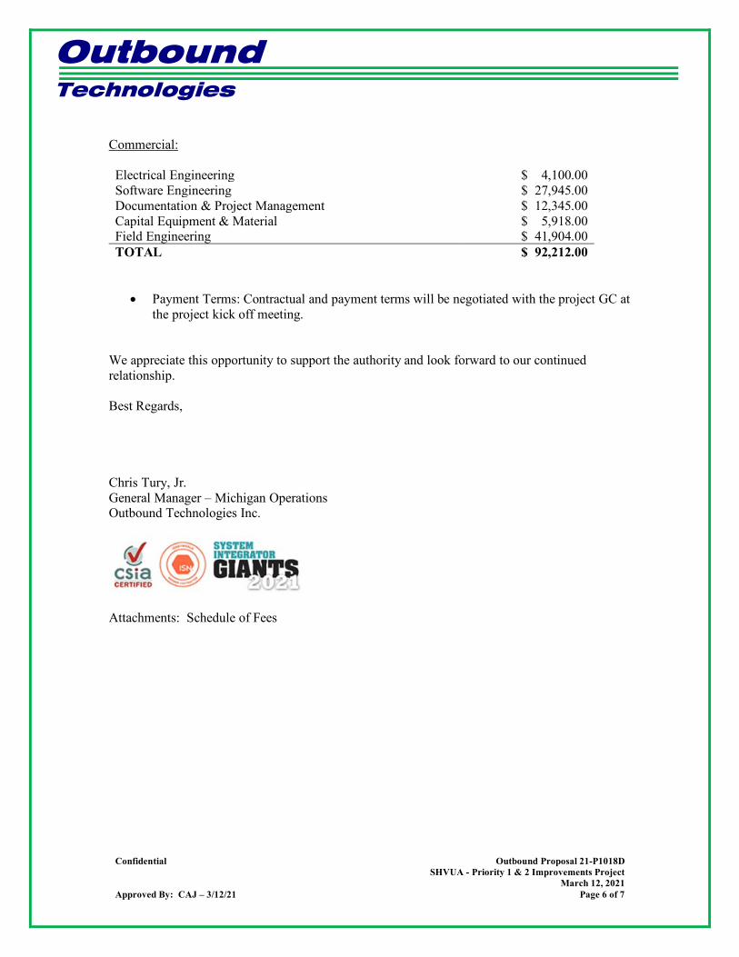
Outbound Technologies
Confidential Outbound Proposal 21-P1018D SHVUA - Priority 1 & 2 Improvements Project
March 12, 2021 Approved By: CAJ – 3/12/21 Page 6 of 7
Commercial: Electrical Engineering $ 4,100.00 Software Engineering $ 27,945.00 Documentation & Project Management $ 12,345.00 Capital Equipment & Material $ 5,918.00 Field Engineering $ 41,904.00 TOTAL $ 92,212.00
• Payment Terms: Contractual and payment terms will be negotiated with the project GC at the project kick off meeting.
We appreciate this opportunity to support the authority and look forward to our continued relationship. Best Regards, Chris Tury, Jr. General Manager – Michigan Operations Outbound Technologies Inc.
Attachments: Schedule of Fees

Outbound Technologies
Confidential Outbound Proposal 21-P1018D SHVUA - Priority 1 & 2 Improvements Project
March 12, 2021 Approved By: CAJ – 3/12/21 Page 7 of 7
SCHEDULE OF FEES
Contract Services Straight Time Over Time Premium Time Documentation Specialist $90.00/hour $103.50/hour $117.00/hour Controls Engineer – Tier 1 $90.00/hour $103.50/hour $117.00/hour Controls Engineer – Tier 2 $105.00/hour $121.00/hour $137.00/hour Controls Engineer – Tier 3 $115.00/hour $132.00/hour $150.00/hour Senior Engineer – Tier 1 $120.00/hour $138.00/hour $156.00/hour Senior Engineer – Tier 2 $125.00/hour $144.00/hour $163.00/hour Senior Engineer – Tier 3 $135.00/hour $155.00/hour $175.50/hour Assistant Engineering Manager $140.00/hour $160.00/hour $182.00/hour Engineering Manager $170.00/hour $195.50/hour $221.00/hour Engineering Director $200.00/hour $230.00/hour $260.00/hour
• Time Definition o Straight Time: 1st (40) hours per week (excluding OTI holidays) o Over Time: Over (40) hours per week (excluding OTI holidays) o Premium Time: OTI holidays
• Travel Time: To and from job site, billed per above rates. • Minimum Billing: (4) hours daily plus travel time • Expenses
o Travel & lodging billed at cost plus 10% gross margin. o Use of personal vehicles billed at IRS Rates plus 10% gross margin. o $60.00 per diem billed for meals, telephone allowance, miscellaneous. o Material and subcontracts will be billed at cost plus 10% gross margin.
• Visits home o For out-of-town services, Outbound policy requires a trip home every (2) weeks: (3) days
of (14) to return home and return to the job site. o Visits home for international travel negotiated at time of order.
• Terms o Invoicing occurs every (2) weeks. o Payment net (30) days from date of invoice. o There will be no retention money withheld or back-charges applied associated with
supplied hourly services. o By purchasing hourly services, the customer understands that Outbound personnel are
being directed and supervised by the customer, daily or weekly. • In purchasing hourly services, customer agrees to provide signature approval to a
daily or weekly Outbound Field Report, regardless of where services are performed, said approval representing approval and acceptance of services for billing purposes.
o Outbound personnel will leave the jobsite prior to the Not To Exceed amount being reached. Adequate forewarning to the customer will be provided on a timely manner for the processing of an addendum by the customer to avoid any delay in project schedule.
o All time and material service requests must be in writing with a formal purchase order or letter of intent, with a Not To Exceed dollar amount.
o In the issuing of a Purchase Order per this Schedule, Customer agrees not to solicit OTI’s employees for hire.
o Warranty items for hourly services (time-and-materials) will be agreed upon during receipt of order. In the absence of this agreement, OTI provides no warranty for hourly services.

SOUTH HURON VALLEY UTILLITY AUTHORITY SHVUE PRIORITY 1 AND 2 IMPROVEMENTS PROJECT
Hubbell, Roth & Clark, Inc. Job 20190897
APPENDIX F
SH 1 Meter Pole
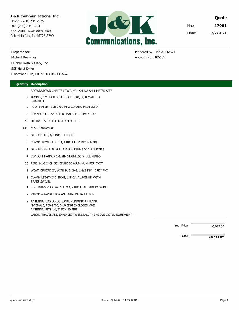
Date:
No.: 47901
3/2/2021
QuoteJ & K Communications, Inc.
Phone: (260) 244-7975
Fax: (260) 244-3253
222 South Tower View Drive
Columbia City, IN 46725-8799
Prepared for: Prepared by: Jon A. Shew II
Michael Roskelley Account No.: 106585
Hubbell Roth & Clark, Inc
555 Hulet Drive
Bloomfield Hills, MI 48303-0824 U.S.A.
Quantity Description
BROWNSTOWN CHARTER TWP, MI - SHUVA SH-1 METER SITE
JUMPER, 1/4 INCH SUREFLEX-MICRO, 3', N-MALE TO
SMA-MALE
2
POLYPHASER - 698-2700 MHZ COAXIAL PROTECTOR2
CONNECTOR, 1/2 INCH N- MALE, POSITIVE STOP4
HELIAX, 1/2 INCH FOAM DIELECTRIC50
MISC HARDWARE1.00
GROUND KIT, 1/2 INCH CLIP ON2
CLAMP, TOWER LEG 1-1/4 INCH TO 2 INCH (J2BB)3
GROUNDING, FOR POLE OR BUILDING ( 5/8" X 8' ROD )1
CONDUIT HANGER 1-1/2IN STAINLESS STEEL/MINI-54
PIPE, 1-1/2 INCH SCHEDULE 80 ALUMINUM, PER FOOT20
WEATHERHEAD 2", WITH BUSHING, 1-1/2 INCH GREY PVC1
CLAMP, LIGHTNING SPIKE, 1.5"-2", ALUMINUM WITH
BRASS SWIVEL
1
LIGHTNING ROD, 24 INCH X 1/2 INCH, ALUMINUM SPIKE1
VAPOR WRAP KIT FOR ANTENNA INSTALLATION2
ANTENNA, LOG DIRECTIONAL PERIODIC ANTENNA
N-FEMALE, 700-2700, 7-10.5DBI ENCLOSED YAGI
ANTENNA, FITS 1-1/2" SCH 80 PIPE
2
LABOR, TRAVEL AND EXPENSES TO INSTALL THE ABOVE LISTED EQUIPMENT--
Your Price: $6,029.87
Total:$6,029.87
quote - no item id.rpt Page 1Printed: 3/2/2021 11:25:16AM
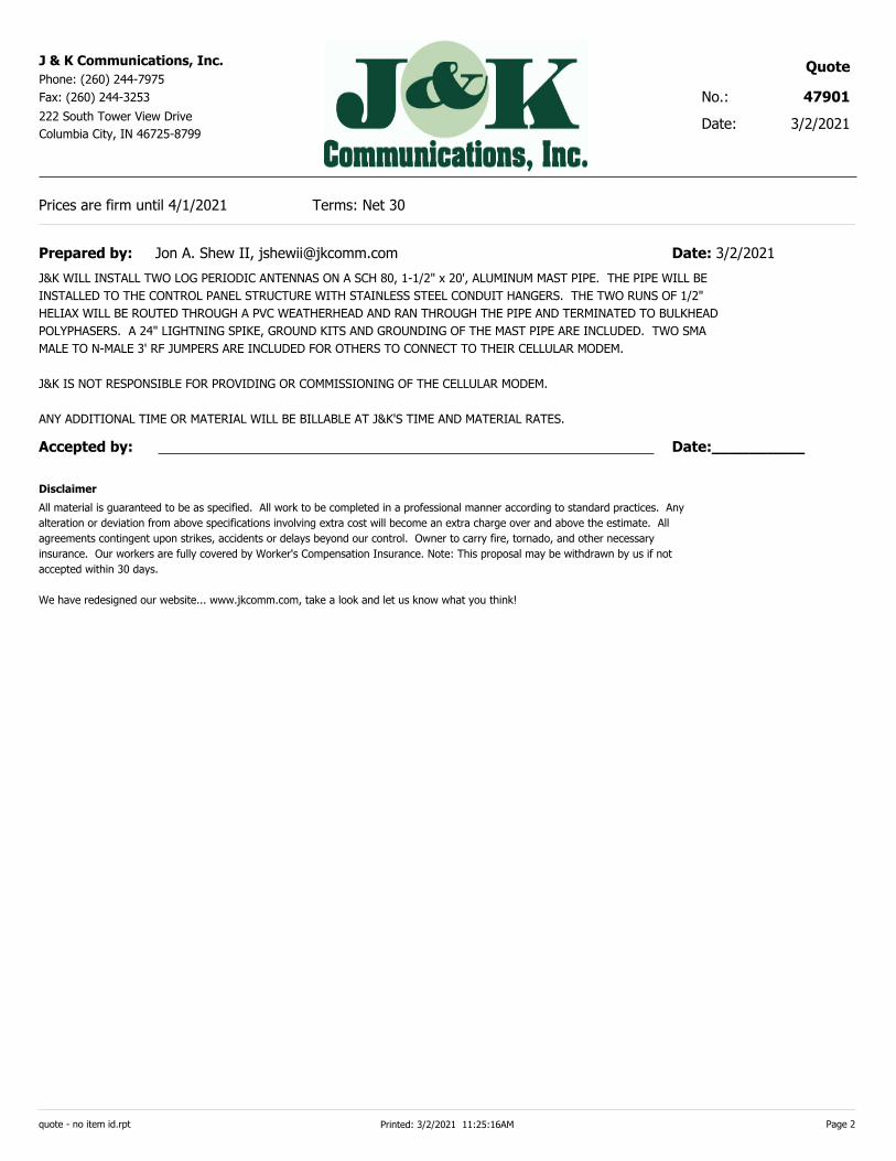
Date:
No.: 47901
3/2/2021
QuoteJ & K Communications, Inc.
Phone: (260) 244-7975
Fax: (260) 244-3253
222 South Tower View Drive
Columbia City, IN 46725-8799
Prices are firm until 4/1/2021 Terms: Net 30
Prepared by: Jon A. Shew II, [email protected] Date: 3/2/2021
J&K WILL INSTALL TWO LOG PERIODIC ANTENNAS ON A SCH 80, 1-1/2" x 20', ALUMINUM MAST PIPE. THE PIPE WILL BE
INSTALLED TO THE CONTROL PANEL STRUCTURE WITH STAINLESS STEEL CONDUIT HANGERS. THE TWO RUNS OF 1/2"
HELIAX WILL BE ROUTED THROUGH A PVC WEATHERHEAD AND RAN THROUGH THE PIPE AND TERMINATED TO BULKHEAD
POLYPHASERS. A 24" LIGHTNING SPIKE, GROUND KITS AND GROUNDING OF THE MAST PIPE ARE INCLUDED. TWO SMA
MALE TO N-MALE 3' RF JUMPERS ARE INCLUDED FOR OTHERS TO CONNECT TO THEIR CELLULAR MODEM.
J&K IS NOT RESPONSIBLE FOR PROVIDING OR COMMISSIONING OF THE CELLULAR MODEM.
ANY ADDITIONAL TIME OR MATERIAL WILL BE BILLABLE AT J&K'S TIME AND MATERIAL RATES.
Date:__________
___________
Accepted by:
All material is guaranteed to be as specified. All work to be completed in a professional manner according to standard practices. Any
alteration or deviation from above specifications involving extra cost will become an extra charge over and above the estimate. All
agreements contingent upon strikes, accidents or delays beyond our control. Owner to carry fire, tornado, and other necessary
insurance. Our workers are fully covered by Worker's Compensation Insurance. Note: This proposal may be withdrawn by us if not
accepted within 30 days.
We have redesigned our website... www.jkcomm.com, take a look and let us know what you think!
Disclaimer
quote - no item id.rpt Page 2Printed: 3/2/2021 11:25:16AM

SOUTH HURON VALLEY UTILLITY AUTHORITY SHVUE PRIORITY 1 AND 2 IMPROVEMENTS PROJECT
Hubbell, Roth & Clark, Inc. Job 20190897
APPENDIX G
HESCO Flow Meters
March 4, 2021 Julie Aichler, PE CDM Smith Subject: Flow Meter Replacement Proposal SHV Priority 1 and 2 Renovations Dear Julie, The following is our proposal to provide technology and field installation services for the upgrade of the flowmeters located at the following locations in the SHUVA collection system: SH-01; SH-06; SH-07, SH-12, SH-14. We understand that a PLC and communication hardware will be provided by others and that HESCO will need to coordinate with these parties at various times throughout the project. These coordination activities are included in our proposal.
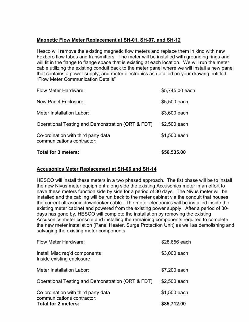
Magnetic Flow Meter Replacement at SH-01, SH-07, and SH-12 Hesco will remove the existing magnetic flow meters and replace them in kind with new Foxboro flow tubes and transmitters. The meter will be installed with grounding rings and will fit in the flange to flange space that is existing at each location. We will run the meter cable utilizing the existing conduit back to the meter panel where we will install a new panel that contains a power supply, and meter electronics as detailed on your drawing entitled “Flow Meter Communication Details” Flow Meter Hardware: $5,745.00 each New Panel Enclosure: $5,500 each
Meter Installation Labor: $3,600 each Operational Testing and Demonstration (ORT & FDT) $2,500 each Co-ordination with third party data $1,500 each communications contractor: Total for 3 meters: $56,535.00 Accusonics Meter Replacement at SH-06 and SH-14 HESCO will install these meters in a two phased approach. The fist phase will be to install the new Nivus meter equipment along side the existing Accusonics meter in an effort to have these meters function side by side for a period of 30 days. The Nivus meter will be installed and the cabling will be run back to the meter cabinet via the conduit that houses the current ultrasonic downlooker cable. The meter electronics will be installed inside the existing meter cabinet and powered from the existing power supply. After a period of 30-days has gone by, HESCO will complete the installation by removing the existing Accusonics meter console and installing the remaining components required to complete the new meter installation (Panel Heater, Surge Protection Unit) as well as demolishing and salvaging the existing meter components Flow Meter Hardware: $28,656 each Install Misc req’d components $3,000 each Inside existing enclosure Meter Installation Labor: $7,200 each Operational Testing and Demonstration (ORT & FDT) $2,500 each Co-ordination with third party data $1,500 each communications contractor: Total for 2 meters: $85,712.00
Co-ordination with third party data communications contractor for Meters SH-2, 3,4,5,8,10,16,17
Total for 8 meters @ $1,500 per meter $12,000.00 Total for providing and installing $154,247.00 5 flow meters and data co-ordination Thank you for allowing us to serve your flow metering needs. As always, we appreciate your trust in us and look forward to working with you. Please give us a call if you have any questions or need additional information. Best Regards, HESCO Kevin Livingston, PE Encl.

SOUTH HURON VALLEY UTILLITY AUTHORITY SHVUE PRIORITY 1 AND 2 IMPROVEMENTS PROJECT
Hubbell, Roth & Clark, Inc. Job 20190897
APPENDIX H
OVIVO SEL Submerged Effluent Launder

OVIVO SEL™
SUBMERGED EFFLUENT LAUNDER
Designs for new and retrofit projects
Eliminates need for launder covers or algae cleaning systems, weir, scum baffle and density current baffle
Significantly reduces installation time and cost
• Eliminates the need to form concrete effluent launders on new tanks
• Self-supporting and requires no external supports
Reduce maintenance cost
• Eliminates need to maintain, adjust and or replace algae brush/spraycleaning systems
Safety: Eliminates need for operator to manually clean effluent launders and its associated safety issues
Minimizes algae growth and downstream algae fouling problems
More forgiving system
• More surface area for settling
• Full surface area skimming
• All components are underwater
• Submerged orifices prevent floatables from exiting into the effluent
• Prevents unequal flow distribution during high winds
• Equal or better effluent quality
• Prevents potential launder cover projectile during high winds
• Minimizes UV degradation
FEATURES AND BENEFITS
MunicipalCLARIFICATION AND
SEDIMENTATION
ovivowater.com [email protected]
Effluent Launder
Weir
Scum Baffle
Density Current Baffle
Launder Cover
ONE COMPONENT SERVING AS FIVE FUNCTIONS
© 2019 Ovivo Inc. All Rights Reserved.
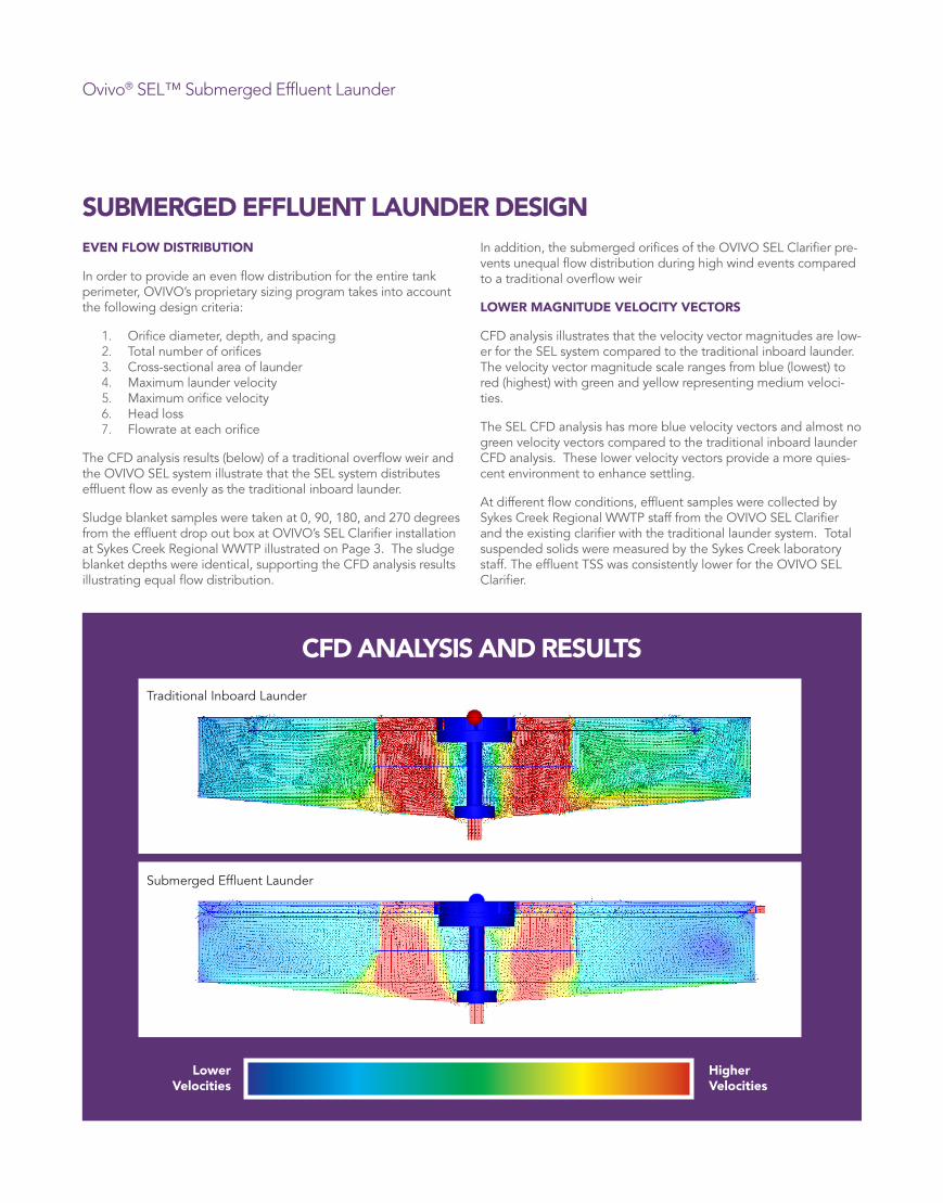
Ovivo® SEL™ Submerged Effluent Launder
SUBMERGED EFFLUENT LAUNDER DESIGNEVEN FLOW DISTRIBUTION
In order to provide an even flow distribution for the entire tank perimeter, OVIVO’s proprietary sizing program takes into account the following design criteria:
1. Orifice diameter, depth, and spacing2. Total number of orifices3. Cross-sectional area of launder4. Maximum launder velocity5. Maximum orifice velocity6. Head loss7. Flowrate at each orifice
The CFD analysis results (below) of a traditional overflow weir and the OVIVO SEL system illustrate that the SEL system distributes effluent flow as evenly as the traditional inboard launder.
Sludge blanket samples were taken at 0, 90, 180, and 270 degrees from the effluent drop out box at OVIVO’s SEL Clarifier installation at Sykes Creek Regional WWTP illustrated on Page 3. The sludge blanket depths were identical, supporting the CFD analysis results illustrating equal flow distribution.
In addition, the submerged orifices of the OVIVO SEL Clarifier pre-vents unequal flow distribution during high wind events compared to a traditional overflow weir
LOWER MAGNITUDE VELOCITY VECTORS
CFD analysis illustrates that the velocity vector magnitudes are low-er for the SEL system compared to the traditional inboard launder. The velocity vector magnitude scale ranges from blue (lowest) to red (highest) with green and yellow representing medium veloci-ties.
The SEL CFD analysis has more blue velocity vectors and almost no green velocity vectors compared to the traditional inboard launder CFD analysis. These lower velocity vectors provide a more quies-cent environment to enhance settling.
At different flow conditions, effluent samples were collected by Sykes Creek Regional WWTP staff from the OVIVO SEL Clarifier and the existing clarifier with the traditional launder system. Total suspended solids were measured by the Sykes Creek laboratory staff. The effluent TSS was consistently lower for the OVIVO SEL Clarifier.
CFD ANALYSIS AND RESULTS
Traditional Inboard Launder
Higher Velocities
Lower Velocities
Submerged Effluent Launder
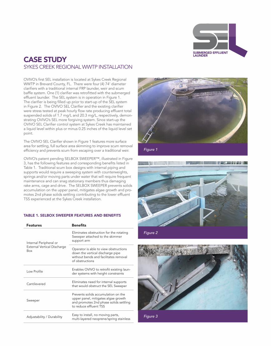
CASE STUDY SYKES CREEK REGIONAL WWTP INSTALLATION
OVIVO’s first SEL installation is located at Sykes Creek Regional WWTP in Brevard County, FL. There were four (4) 74’ diameter clarifiers with a traditional internal FRP launder, weir and scum baffle system. One (1) clarifier was retrofitted with the submerged effluent launder. The SEL system is in operation in Figure 1. The clarifier is being filled up prior to start-up of the SEL system in Figure 2. The OVIVO SEL Clarifier and the existing clarifier were stress tested at peak hourly flow rate producing effluent total suspended solids of 1.7 mg/L and 20.3 mg/L, respectively, demon-strating OVIVO’s SEL more forgiving system. Since start-up the OVIVO SEL Clarifier control system at Sykes Creek has maintained a liquid level within plus or minus 0.25 inches of the liquid level set point.
The OVIVO SEL Clarifier shown in Figure 1 features more surface area for settling, full surface area skimming to improve scum removal efficiency and prevents scum from escaping over a traditional weir.
OVIVO’s patent pending SELBOX SWEEPER™, illustrated in Figure 3, has the following features and corresponding benefits listed in Table 1. Traditional scum box designs with internal piping and supports would require a sweeping system with counterweights, springs and/or moving parts under water that will require frequent maintenance and can snag stationary members thus damaging rake arms, cage and drive. The SELBOX SWEEPER prevents solids accumulation on the upper panel, mitigates algae growth and pro-motes 2nd phase solids settling contributing to the lower effluent TSS experienced at the Sykes Creek installation.
TABLE 1. SELBOX SWEEPER FEATURES AND BENEFITS
Features Benefits
Internal Peripheral or External Vertical Discharge Box
Eliminates obstruction for the rotating Sweeper attached to the skimmer support arm
Operator is able to view obstructions down the vertical discharge pipe without bends and facilitates removal of obstructions
Low Profile Enables OVIVO to retrofit existing laun-der systems with height constraints
Cantilevered Eliminates need for internal supports that would obstruct the SEL Sweeper
Sweeper
Prevents solids accumulation on the upper panel, mitigates algae growth and promotes 2nd phase solids settling to reduce effluent TSS
Adjustability / Durability Easy to install, no moving parts, multi-layered neoprene/spring stainless
Figure 1
Figure 2
Figure 3
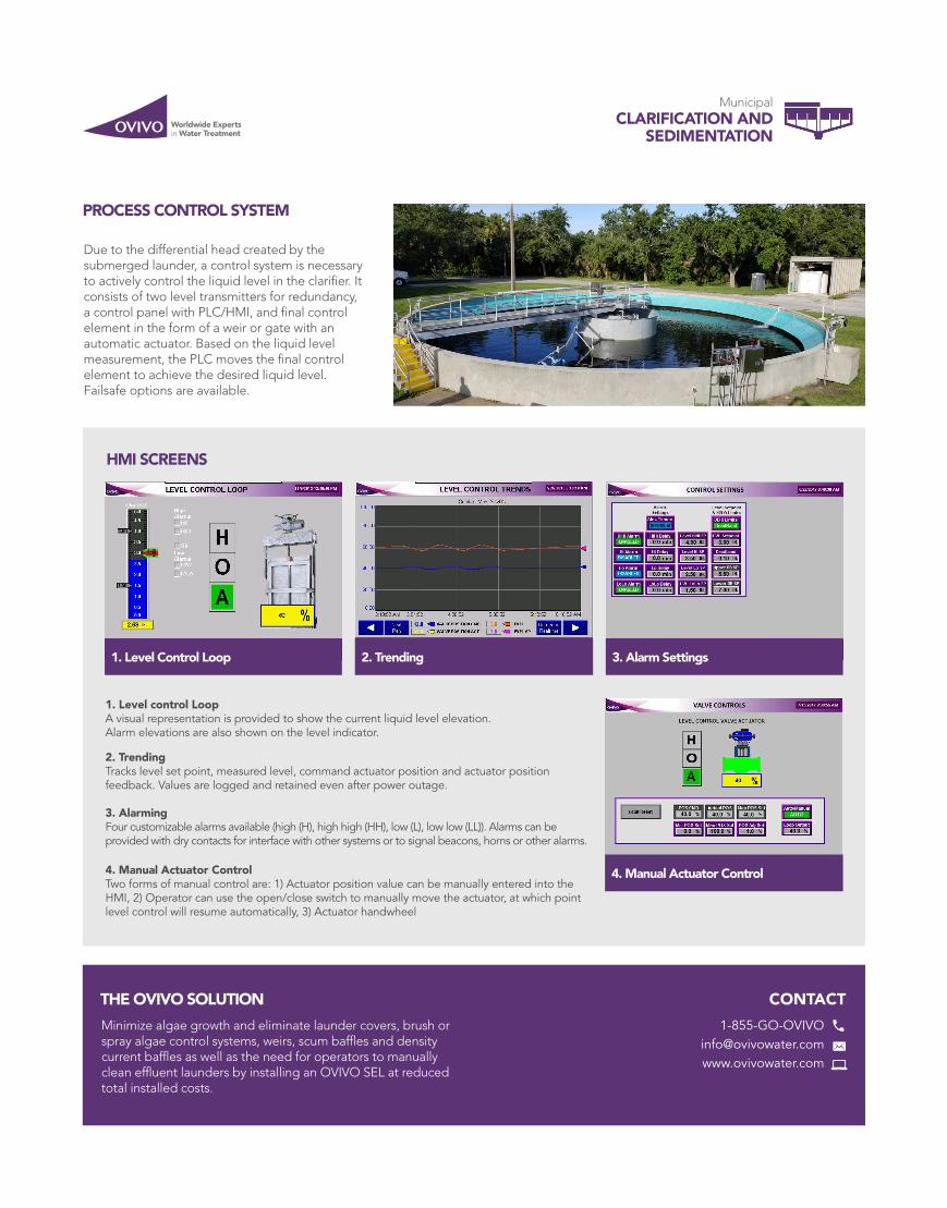
Worldwide Expertsin Water Treatment
CONTACT
PROCESS CONTROL SYSTEM
THE OVIVO SOLUTION
Due to the differential head created by the submerged launder, a control system is necessary to actively control the liquid level in the clarifier. It consists of two level transmitters for redundancy, a control panel with PLC/HMI, and final control element in the form of a weir or gate with an automatic actuator. Based on the liquid level measurement, the PLC moves the final control element to achieve the desired liquid level. Failsafe options are available.
Minimize algae growth and eliminate launder covers, brush or spray algae control systems, weirs, scum baffles and density current baffles as well as the need for operators to manually clean effluent launders by installing an OVIVO SEL at reduced total installed costs.
1. Level control LoopA visual representation is provided to show the current liquid level elevation.Alarm elevations are also shown on the level indicator.
2. TrendingTracks level set point, measured level, command actuator position and actuator positionfeedback. Values are logged and retained even after power outage.
3. AlarmingFour customizable alarms available (high (H), high high (HH), low (L), low low (LL)). Alarms can be provided with dry contacts for interface with other systems or to signal beacons, horns or other alarms.
4. Manual Actuator ControlTwo forms of manual control are: 1) Actuator position value can be manually entered into theHMI, 2) Operator can use the open/close switch to manually move the actuator, at which pointlevel control will resume automatically, 3) Actuator handwheel
HMI SCREENS
1. Level Control Loop 3. Alarm Settings2. Trending
4. Manual Actuator Control
MunicipalCLARIFICATION AND
SEDIMENTATION

SOUTH HURON VALLEY UTILLITY AUTHORITY SHVUE PRIORITY 1 AND 2 IMPROVEMENTS PROJECT
Hubbell, Roth & Clark, Inc. Job 20190897
APPENDIX I
Geotech Report Odette PS
Report on Geotechnical Investigation
South Huron Valley Utility
Authority Waste Water
Treatment Plant
Improvements
NE Quadrant of Odette
Road and W. Huron River
Drive
Huron Charter Township,
Michigan 48134
Latitude 42.114318˚ N
Longitude 83.318479 ˚ W
Prepared for:
Hubbell, Roth, & Clark, Inc.
555 Hulet Drive
Bloomfield Hills, Michigan 48302
G2 Project No. 203246
January 11, 2021

January 11, 2021
Ms. Christa K. Crist, P.E.
Senior Project Engineer
Hubbell, Roth, & Clark, Inc.
555 Hulet Drive
Bloomfield Hills, Michigan 48302
Re: Report on Geotechnical Investigation
South Huron Valley Utility Authority Waste Water Treatment Plant Improvements
NE Quadrant of Odette Road and W. Huron River Drive
Huron Charter Township, Michigan 48134
G2 Project No. 203246
Dear Ms. Crist:
We have completed the geotechnical investigation for the construction of the proposed South Huron
Valley Utility Authority (SHVUA) Waste Water Treatment Plant (WWTP) pump station improvements
located at the aforementioned address in Huron Charter Township, Michigan. This report presents the
results of our observations, analyses, and our recommendations for subgrade preparation and
construction of the proposed valve vault.
We appreciate the opportunity to be of service to Hubbell, Roth, & Clark, Inc. (HRC) and look forward to
discussing the recommendations presented. In the meantime, if you have any questions regarding the
report or any other matter pertaining to the project, please call us.
Sincerely,
G2 Consulting Group, LLC
Charles Saintcyr, P.E.
Project Engineer
James L. Berry, P.E.
Project Manager
CKS/JLB/NJHT/ljv
Enclosures

January 11, 2021
G2 Project No. 203246
Page 1
EXECUTIVE SUMMARY
The South Huron Valley Utility Authority (SHVUA) is planning improvements to an existing pump station
located at the corner of Odette Road and Huron River Drive, Huron Charter Township, Michigan. We
understand the project includes abandoning and backfilling the existing dry well structure, constructing
a new concrete valve vault on top of the abandoned / backfilled dry well, and placing a new riser section
on top of the existing wet well structure. Both the existing wet well and the existing dry well are
supported on single mat foundation bearing approximately 25-1/2 feet below existing site grade.
We drilled a total of two (2) soil borings adjacent to the existing pump station. Approximately 4 inches
of topsoil are present at the ground surface within the borings. Very stiff to hard silty clay fill soils
generally underlie the topsoil and extend to approximate depths of 9 feet at B-1 and 6 feet at B-2,
additionally, a layer of medium silty clay fill is present at B-1 from 11 feet to 19 feet. Very loose to loose
clayey sand and sand fill soils are present below the silty clay fill and extend to approximate depths
ranging from 26-1/2 to 21-1/2 feet for B-1 and B-2, respectively. Completely weathered limestone
bedrock underlies the fill soils and extends to the explored depths of 22 and 27 feet below the ground
surface.
Groundwater measurements were performed during and upon completion of drilling operations. During
drilling operations, groundwater was encountered at a depth of 13-1/2 feet and 16 feet below the
ground surface (Elevations 586.1 and 584.7) within borings B-1 and B-2, respectively. Upon completion
of the drilling operations, groundwater was observed at a depth of 12 feet below the ground surface
(Elevations 587.6 and 588.7).
Based on our understanding of the project, the proposed valve vault will extend approximately 11 feet
below the existing ground to an elevation of 589.1 feet. Modifications to the wet well include placement
of a new riser section on top of the existing structure, which is approximately 15.5 feet below existing
grade at an elevation of 585.5 feet. Based on the provided drawing prepared by HRC, Project No.
20190897, and Sheet No. OS-01, a temporary earth retention system will be installed surrounding the
excavation. For design of cantilevered or single row internally braced shoring, we recommend the use of
a triangular distribution of lateral earth pressure (active earth pressure) above the excavation line. It
may be assumed that the retained soils with a level surface behind the cantilevered shoring will exert a
lateral pressure equal to that developed by a fluid with a density of 35 pounds per cubic foot (pcf) for
soils above water level. Soils below the water table should be modeled as a fluid with a density of 85
pcf. If construction or road traffic or material storage is allowed within the influence of the excavation, a
uniform surcharge pressure of 250 pounds per square foot should be added to the design load.
Based on the soil conditions encountered at the soil borings, we anticipate the existing mat foundation
is bearing on the completely weathered limestone bedrock. We anticipate the existing mat foundation
bearing soils can support the additional weight of the structural flowable fill or lean concrete backfill,
proposed base slab, and both concrete riser sections. If the recommendations outlined in this report are
adhered to, total and differential settlements for the completed structure should be negligible.
We anticipate groundwater will be encountered within construction excavations. Groundwater was
measured within B-1 and B-2 at elevations of 586.1 and 584.7 feet during drilling. It is anticipated that
the construction excavation extending to elevation 585.5 feet can be maintained in a relatively dry
condition by installing a temporary earth retention system around the excavation, and using
conventional minor dewatering measures such as pumping from properly constructed sumps.
Do not consider this summary separate from the entire text of this report, with all the conclusions and
qualifications mentioned herein. Details of our analysis and recommendations are discussed in the
following sections and in the Appendix of this report.
January 11, 2021
G2 Project No. 203246
Page 2
PROJECT DESCRIPTION
The South Huron Valley Utility Authority (SHVUA) is planning improvements to an existing pump station
located at the corner of Odette Road and Huron River Drive Huron Charter Township, Michigan. We
understand the project includes abandoning and backfilling the existing dry well structure, constructing
a new concrete valve vault on top of the abandoned / backfilled dry well, and placing a new riser section
on top of the existing wet well structure. Both the existing wet well and the existing dry well are
supported on single mat foundation bearing approximately 25-1/2 feet below existing site grade.
The proposed concrete valve vault will be an 8-foot interior diameter precast concrete structure, founded
on a cast in place base slab. The base slab of the proposed structure will be constructed atop the
existing steel dry well approximately 11 feet below existing grade or at an elevation of 590 feet. The
existing steel dry well will be abandoned and backfilled with structural flowable fill or lean concrete prior
to the proposed valve vault construction. Additionally, the existing wet well will be outfitted with
submersible pumps and a new concrete riser section will be placed on top of the existing top slab, which
is at an elevation of approximately 585.5 feet. Both existing structures are currently supported on an 11
foot wide by 24 foot long and 12-inch thick base slab with a bottom of slab elevation of approximately
574.5 feet.
Based on the provided drawing titled “Sanitary Sewer Outfall System Details” – prepared by Wayne County
Road Commissioners, Project No. S-226, Sheet No. 36, existing site elevation is approximately 600.1
feet. Furthermore, the spread footing for the existing structures has an approximate top elevation of
575.5 feet. We understand, final site grades will be within 1 to 2 feet of existing grades.
If information related to structural loading conditions or final site grades vary from the anticipate
conditions above or change, G2 Consulting Group, LLC (G2) should be notified so that we can re-evaluate
the recommendations presented herein. The purpose of our exploration is to determine the general
subsurface conditions at the site and to develop recommendations for the subgrade preparation,
foundation design, and construction considerations for the proposed pump station as they relate to the
geotechnical conditions at the site.
SCOPE OF SERVICES
The field operations, laboratory testing, and engineering report preparation were performed under
direction and supervision of a licensed professional engineer. Our services were performed according to
generally accepted standards and procedures in the practice of geotechnical engineering in this area.
Our scope of services for this project is as follows:
1. We drilled a total of two (2) soil borings adjacent to the existing development. The soil borings
were performed to the east and southeast of the existing structure and extended to 22 feet and
27 feet below ground surface.
2. We performed laboratory testing on representative samples obtained from the soil borings.
Laboratory testing included visual engineering classification, natural moisture content, grain size
distributions, and unconfined compressive strength determinations.
3. We prepared this engineering report. The report includes recommendations regarding the soil
bearing capacity, estimated settlement, and construction considerations related to construction
of the proposed pump station.
FIELD OPERATIONS
Hubbell, Roth, & Clark, Inc., (HRC), in conjunction with G2, selected the depths and locations of the soil
borings. The soil boring locations were located in the field by HRC prior to our drilling operations. The
approximate soil boring locations are shown on the attached Soil Boring Location Plan, Plate No. 1. The
ground surface elevations at the soil boring locations were provide by HRC.

January 11, 2021
G2 Project No. 203246
Page 3
The soil borings were drilled using a truck-mounted rotary drilling rig. Continuous flight, 3-1/4 inch
inside diameter, hollow stem augers were used to advance the boreholes to the explored depths. Soil
samples were obtained at intervals of 2-1/2 feet within the upper 10 feet and at intervals of 5 feet
thereafter. The samples were obtained by the Standard Penetration Test method (ASTM D 1586), which
involves driving a 2-inch diameter split-spoon sampler into the soil with a 140-pound weight falling 30
inches. The sampler is generally driven three successive 6-inch increments with the number of blows for
each increment recorded. The number of blows required to advance the sampler the last 12 inches is
termed the Standard Penetration Resistance (N). The blow counts for each 6-inch increment and the
resulting N-value are presented on the soil boring logs.
The soil samples were placed in sealed containers and brought to our laboratory for testing and
classification. During field operations, the drillers maintained a log of the subsurface conditions,
including changes in stratigraphy and observed groundwater levels. The final boring logs, Figure Nos. 1
and 2, are based on the field boring logs supplemented by laboratory soil classification and test results.
In general, the soil borings were backfilled with cement grout.
LABORATORY TESTING
Representative soil samples were subjected to laboratory testing to determine soil parameters pertinent
to foundation design and site preparation. An experienced geotechnical engineer classified the samples
in general conformance with the Unified Soil Classification System.
Laboratory testing included natural moisture content, grain size distributions, and unconfined
compressive strength determinations. The grain size distributions were determined in accordance with
ASTM Test Method D422, “Standard Test Method for Particle-Size Analysis of Soils”. The unconfined
compressive strengths were determined by ASTM D2166, and using a spring-loaded hand penetrometer.
The hand penetrometer estimates the unconfined compressive strength to a maximum of 4-1/2 tons per
square foot (tsf) by measuring the resistance to the soil sample to the penetration of a calibrated spring
loaded cylinder.
The results of the moisture contents and unconfined compressive strengths are indicated on the soil
boring logs at the depths the samples were obtained. In addition, the results of the grain size
distributions are represented graphically in the Appendix as Figure No. 3. We will hold the soil samples
for 60 days from the date of this report, after which time they will be discarded. If you would like the
samples, please let us know.
SITE DESCRIPTION
The existing SHVUA pump station is located in the northeast corner of the intersection of Odette Road
and West Huron River Drive in Huron Charter Township, Michigan. The pump station currently consists
of one wet well and one dry well and associated mechanical and electrical equipment. In general, the
site is grass covered with the surrounding properties being agricultural and residential in nature.
The development is bounded by Odette Road to the West and the W. Huron River Drive to the south.
Based on the provided drawing titled “Sanitary Sewage Outfall System” – prepared by Wayne County Road
Commissioners, Project No. S-226, Sheet No. 36 existing elevation is at approximately 600.1 feet.
Based on information available through the Federal Emergency Management Agency (FEMA), the SHVUA
development does not appear to be within the influence of the flood plain area. Based on maps
provided by FEMA, it appears that flood elevation is below the lowest elevation at the proposed project
site.
January 11, 2021
G2 Project No. 203246
Page 4
SOIL CONDITIONS
Approximately 4 inches of topsoil are present at the ground surface within the borings. Silty clay fill
soils underlie the topsoil and extend to approximate depths of 9 feet at B-1 and 6 feet at B-2,
additionally, a layer of silty clay fill is present at B-1 from 11 feet to 19 feet below the ground surface.
Clayey sand and sand fill soils are present below the silty clay fill and extend to approximate depths
ranging from 26-1/2 to 21-1/2 feet below the ground surface for B-1 and B-2, respectively. Completely
weathered limestone underlies the fill soils and extends to the explored depths of 22 and 27 feet below
the ground surface.
The silty clay fill soils are generally very stiff to hard in consistency, with moisture contents ranging from
13 to 21 percent, and unconfined compressive strengths ranging from 5,000 to 8,000 psf. The layer of
silty clay fill at B-1 between 11 and 19 feet is medium in consistency, with a natural moisture content of
23 percent and an unconfined compressive strength of 1,000 psf. The granular fill material is generally
very loose to loose in compactness with Standard Penetration Test N-values ranging from Weight of
Hammer (WOH) over 18 inches to 5 blows per foot. The completely weathered limestone is very weak to
moderately weak in rock strength with an N-value of 50 blows per 1 inch of penetration.
The stratification depths shown on the soil boring logs represent the soil conditions at the boring
locations. Variations may occur away from the boring location. Additionally, the stratigraphic lines
represent the approximate boundaries between soil types. The transition may be more gradual than
indicated. We have prepared the boring logs on the basis of the field log of the soil conditions
encountered supplemented by laboratory classification and testing.
The Soil Boring Location Plan, Plate No. 1, Soil Boring Logs, Figure Nos. 1 and 2, and the grain size
distributions, Figure No. 3, are presented in the Appendix. The soil profiles described above are
generalized descriptions of the conditions encountered at the boring locations. General Notes
Terminology and Classification of Rock Strata defining the nomenclature used on the soil boring logs
and elsewhere in this report are presented on Figure Nos. 4 and 5, respectively.
GROUNDWATER CONDITIONS
Groundwater measurements were performed during and upon completion of drilling operations. During
drilling operations, groundwater was encountered at a depth of 13-1/2 feet and 16 feet below the
ground surface (Elevations 586.1 and 584.7) within borings B-1 and B-2, respectively. Upon completion
of the drilling operations, groundwater was observed at a depth of 12 feet below the ground surface
(Elevations 587.6 and 588.7).
Fluctuations in perched and long-term groundwater levels should be anticipated due to seasonal
variations and following periods of prolonged precipitation. It should also be noted that groundwater
observations made during drilling operations in predominantly cohesive soils are not necessarily
indicative of the static groundwater level. This is due to the low permeability of such soils and the
tendency of drilling operations to seal off the natural paths of groundwater flow.
SITE SEISMICITY
Wayne County lies in a stable tectonic region of the country characterized by a relatively low expected
magnitude of ground accelerations during an earthquake event. Based on the subsurface conditions, we
recommend a seismic site classification of D. Based on the type of structure, seismic analyses were
based on a Risk Category II and IBC 2015.
January 11, 2021
G2 Project No. 203246
Page 5
Spectral Response Category
Response Acceleration
at Short Periods
Response Acceleration at One
Second Period
Maximum
Considered Earthquake SS = 0.104 g S1 = 0.049 g
Adjusted Maximum
Considered Earthquake SMS = 0.166 g SM1 = 0.118 g
Five Percent
Damped Design SDS = 0.111 g SD1 = 0.079 g
In the event of an earthquake having a maximum ground acceleration of 0.166 g, there is a very low
potential for localized liquefaction to occur within predominately cohesive soils. Given the site is also in
an area with a low probability of occurrence for seismic activity, we believe the risk for liquefaction at
the site is also low.
SITE PREPARATION
Based on our understanding of the project, the proposed valve vault will extend approximately 11 feet
below the existing ground to an elevation of 590 feet. Modifications to the wet well include placement
of a new riser section on top of the existing structure, which is approximately 15.5 feet below existing
grade at an elevation of 585.5 feet. To complete the work, we anticipate earthwork operations will
consist of installing a temporary earth retention system around the existing structures, excavating
around the existing structures to a maximum depth of approximately 15.5 feet, removing existing risers
and utilities associated with the existing structures, backfilling the existing steel dry well with structural
flowable fill or lean concrete, placing the cast in place valve vault base slab, setting the new riser
sections and top slabs, and placing and compacting engineered fill around the new structures. We
recommend all earthwork operations be performed in accordance with comprehensive specifications and
be properly monitored in the field by qualified personnel under the direction of a licensed professional
engineer.
Resulting excavations should be backfilled with engineered fill. Grain size analyses were performed on
the sand and clayey sand obtained from boring B-2. Test results indicate the existing granular fill
material is not suitable for reuse as backfill material. We recommend that the backfill material consist of
a free-draining soil, such as an MDOT Class IIA Sand.
Engineered fill should be free of organic matter, frozen soil, clods, or other harmful material. The fill
should be placed in uniform horizontal layers that are not more than 9 inches in loose thickness. The
engineered fill should be compacted to achieve a density of at least 95 percent of the maximum dry
density as determined by the Modified Proctor compaction test (ASTM D 1557). All engineered fill
material should be placed and compacted at approximately the optimum moisture content. Frozen
material should not be used as fill, nor should fill be placed on a frozen subgrade.
FOUNDATION RECOMMENDATIONS
We understand the project is currently designed to have the proposed structures sit on top of the
existing wet well top slab and the existing dry well steel casing backfilled with structural flowable fill or
lean concrete. It is understood that the full load of the new well riser and top will be supported by the
existing concrete substructure, and the full load of the new vault structure will be supported by the filled
backfilled dry well structure. None of the new structural loads will be supported on existing backfill
soils. Both existing structures share an 11 foot wide by 24 foot long and 12-inch thick mat foundation
with a bottom of slab elevation of approximately 574.5 feet.
As previously mentioned, we anticipate the proposed valve vault base slab will be approximately 11 feet
below the ground surface. This will result in a bottom of slab elevation of approximately Elevation 589
feet. The reinforced concrete slab will extend beyond the outside perimeter of the existing wall face by

January 11, 2021
G2 Project No. 203246
Page 6
about 2 feet. Due to the bearing elevation of the proposed base slab, there will be no frost-heave
mechanisms of the bearing soil.
Based on the soil conditions encountered at the soil borings, we anticipate the existing mat foundation
is bearing on the completely weathered limestone bedrock. We anticipate the foundation bearing soils
can support the additional weight of the structural flowable fill / lean concrete backfill, proposed vault
structure, and wet well concrete riser section. If the recommendations outlined in this report are
adhered to, total and differential settlements for the completed structure should be negligible. We
expect settlements of these magnitudes are within tolerable limits for the proposed pump station. We
recommend all base slabs and other structural elements be suitably reinforced to minimize the effects of
differential settlements associated with local variations in subsoil conditions. Due to the encountered
soils on site, we do not anticipate other settlement mechanisms, such as settlement related to
liquefaction, will be applicable.
LATERAL EQUIVALENT SOIL PRESSURES
Since the proposed riser sections will be relatively stiff, we recommend that the permanent below grade
walls be designed for an “at rest” lateral earth pressure. We recommend that the excavation required to
construct the underground portion of the wet and dry wells be backfilled with granular engineered
backfill. As such, the below grade walls should be designed based on an equivalent liquid earth
pressure of 55 pounds per square foot (psf) per foot of depth from the ground surface to the long-term
groundwater level of approximate elevation of 587 feet. Below Elevation 587, we recommend a design
equivalent liquid earth pressure of 90 psf/ft.
CONSTRUCTION CONSIDERATIONS
We anticipate groundwater will be encountered within construction excavations. Groundwater was
measured within B-1 and B-2 at elevations of 586.1 and 584.7 feet during drilling. It is anticipated that
the construction excavation extending to elevation 585.5 feet can be maintained in a relatively dry
condition by installing a temporary earth retention system around the excavation, and using
conventional minor dewatering measures such as pumping from properly constructed internal sumps.
Based on the provided drawing prepared by HRC, Project No. 20190897, and Sheet No. OS-01, a
temporary earth retention system will be installed surrounding the excavation. For design of
cantilevered or single row internally braced shoring, we recommend the use of a triangular distribution
of lateral earth pressure (active earth pressure) above the excavation line. It may be assumed that the
retained soils with a level surface behind the cantilevered shoring will exert a lateral pressure equal to
that developed by a fluid with a density of 35 pounds per cubic foot (pcf) for soils above water level.
Soils below the water table should be modeled as a fluid with a density of 85 pcf. If construction or road
traffic or material storage is allowed within the influence of the excavation, a uniform surcharge
pressure of 250 pounds per square foot should be added to the design load.
All excavations should be safely sheeted, shored, sloped, or braced in accordance with MI-OSHA
requirements. Care should always be exercised when excavating near existing utilities, if present, to
avoid undermining. In no case should excavations extend below the level of adjacent structures unless
underpinning is planned.
GENERAL COMMENTS
We have formulated the evaluations and recommendations presented in this report relative to site
preparation and foundations on the basis of data provided to us relating to the project location, type of
structure, and surface grade for the proposed site. Any significant change in this data should be
brought to our attention for review and evaluation with respect to prevailing subsurface conditions.
Furthermore, if changes occur in the design, location, or concept of the project, conclusions and
recommendations contained in this report are not valid unless G2 Consulting Group, LLC reviews the
January 11, 2021
G2 Project No. 203246
Page 7
changes. G2 Consulting Group, LLC will then confirm the recommendations presented herein or make
changes in writing.
The scope of the present investigation was limited to evaluation of subsurface conditions for the support
of the proposed pump station and other related aspects of the development. No chemical,
environmental, or hydrogeological testing or analyses were included in the scope of this investigation.
We base the analyses and recommendations submitted in this report upon the data from the soil borings
performed at the approximate locations shown on the Soil Boring Location Plan, Plate No. 1. This report
does not reflect variations that may occur between the actual boring location and the actual structure
locations. The nature and extent of any such variations may not become clear until the time of
construction. If significant variations then become evident, it may be necessary for us to re-evaluate our
report recommendations.
We recommend G2 Consulting Group, LLC observe all geotechnical related work, including foundation
construction, subgrade preparation, and engineered fill placement. G2 Consulting Group, LLC will
perform the appropriate testing to confirm the geotechnical conditions given in the report are found
during construction.

APPENDIX
Soil Boring Location Plan Plate No. 1
Soil Boring Logs Figure No. 1 through 2
Grain Size Distributions Figure No. 3
General Notes Terminology Figure No. 4
Classification of Rock Strata Figure No. 5
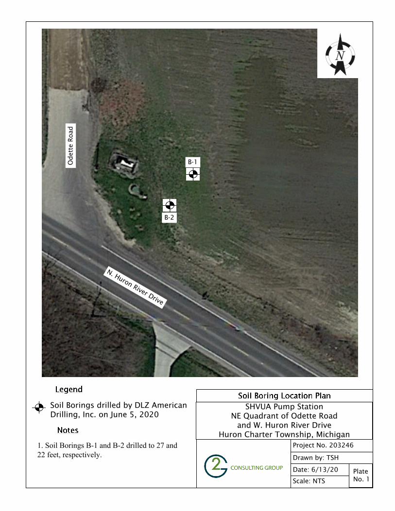
Scale: NTS
Date: 6/13/20
Drawn by: TSH
Project No. 203246
Plate No. 1
SHVUA Pump StationNE Quadrant of Odette Road
and W. Huron River DriveHuron Charter Township, Michigan
Soil Borings drilled by DLZ AmericanDrilling, Inc. on June 5, 2020
B-2
1. Soil Borings B-1 and B-2 drilled to 27 and22 feet, respectively.
N. Huron River Drive
Odet
te R
oad
B-1
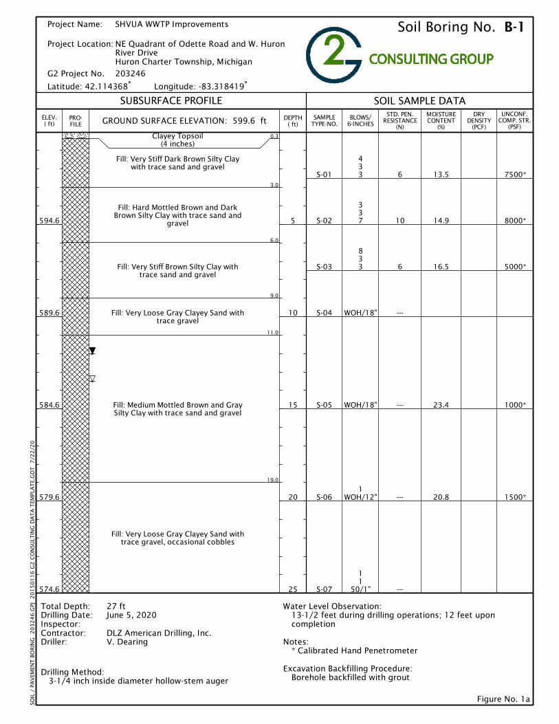
S-01
S-02
S-03
S-04
S-05
S-06
S-07
433
337
833
WOH/18"
WOH/18"
1WOH/12"
11
50/1"
6
10
6
---
---
---
---
13.5
14.9
16.5
23.4
20.8
7500*
8000*
5000*
1000*
1500*
0.3
3.0
6.0
9.0
11.0
19.0
Clayey Topsoil(4 inches)
Fill: Very Stiff Dark Brown Silty Claywith trace sand and gravel
Fill: Hard Mottled Brown and DarkBrown Silty Clay with trace sand and
gravel
Fill: Very Stiff Brown Silty Clay withtrace sand and gravel
Fill: Very Loose Gray Clayey Sand withtrace gravel
Fill: Medium Mottled Brown and GraySilty Clay with trace sand and gravel
Fill: Very Loose Gray Clayey Sand withtrace gravel, occasional cobbles
SAMPLETYPE-NO.
BLOWS/6-INCHES
STD. PEN.RESISTANCE
(N)
MOISTURECONTENT
(%)
DRYDENSITY
(PCF)
UNCONF.COMP. STR.
(PSF)
SOIL SAMPLE DATA
SOIL
/ P
AV
EMEN
T B
OR
ING
2
03
24
6.G
PJ
20
15
01
16
G2
CO
NSU
LTIN
G D
AT
A T
EMPL
AT
E.G
DT
7
/22
/20
Soil Boring No. B-1
SUBSURFACE PROFILE
Figure No. 1a
Water Level Observation:13-1/2 feet during drilling operations; 12 feet uponcompletion
Notes:* Calibrated Hand Penetrometer
Excavation Backfilling Procedure:Borehole backfilled with grout
PRO-FILE
DEPTH( ft)
5
10
15
20
25
G2 Project No. 203246
Project Name:
Project Location:
SHVUA WWTP Improvements
NE Quadrant of Odette Road and W. HuronRiver DriveHuron Charter Township, Michigan
GROUND SURFACE ELEVATION: 599.6 ft
Total Depth:Drilling Date:Inspector:Contractor:Driller:
Drilling Method: 3-1/4 inch inside diameter hollow-stem auger
27 ftJune 5, 2020
DLZ American Drilling, Inc.V. Dearing
ELEV.( ft)
594.6
589.6
584.6
579.6
574.6
Latitude: 42.114368 Longitude: -83.318419
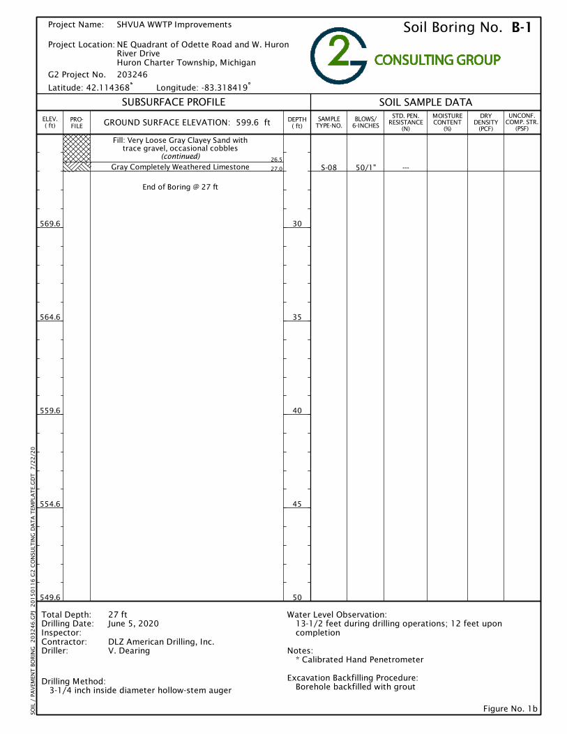
S-08 50/1" ---26.5
27.0
Fill: Very Loose Gray Clayey Sand withtrace gravel, occasional cobbles
(continued)
Gray Completely Weathered Limestone
End of Boring @ 27 ft
SAMPLETYPE-NO.
BLOWS/6-INCHES
STD. PEN.RESISTANCE
(N)
MOISTURECONTENT
(%)
DRYDENSITY
(PCF)
UNCONF.COMP. STR.
(PSF)
SOIL SAMPLE DATA
SOIL
/ P
AV
EMEN
T B
OR
ING
2
03
24
6.G
PJ
20
15
01
16
G2
CO
NSU
LTIN
G D
AT
A T
EMPL
AT
E.G
DT
7
/22
/20
Soil Boring No. B-1
SUBSURFACE PROFILE
Figure No. 1b
Water Level Observation:13-1/2 feet during drilling operations; 12 feet uponcompletion
Notes:* Calibrated Hand Penetrometer
Excavation Backfilling Procedure:Borehole backfilled with grout
PRO-FILE
DEPTH( ft)
30
35
40
45
50
G2 Project No. 203246
Project Name:
Project Location:
SHVUA WWTP Improvements
NE Quadrant of Odette Road and W. HuronRiver DriveHuron Charter Township, Michigan
GROUND SURFACE ELEVATION: 599.6 ft
Total Depth:Drilling Date:Inspector:Contractor:Driller:
Drilling Method: 3-1/4 inch inside diameter hollow-stem auger
27 ftJune 5, 2020
DLZ American Drilling, Inc.V. Dearing
ELEV.( ft)
569.6
564.6
559.6
554.6
549.6
Latitude: 42.114368 Longitude: -83.318419

S-01
S-02
S-03
S-04
S-05
S-06
S-07
644
323
222
1WOH
1
112
232
50/1"
8
5
4
---
3
5
---
13.4
20.7
8000*
5000*
0.3
6.0
13.0
21.5
22.0
Clayey Topsoil(4 inches)
Fill: Very Stiff to Hard Dark Brown SiltyClay with trace sand, gravel, and roots
Fill: Very Loose Light Brown Sand withtrace silt and gravel, occasional silty
clay clods
Fill: Very Loose to Loose Gray ClayeySand with trace gravel
Gray Completely Weathered Limestone
End of Boring @ 22 ft
SAMPLETYPE-NO.
BLOWS/6-INCHES
STD. PEN.RESISTANCE
(N)
MOISTURECONTENT
(%)
DRYDENSITY
(PCF)
UNCONF.COMP. STR.
(PSF)
SOIL SAMPLE DATA
SOIL
/ P
AV
EMEN
T B
OR
ING
2
03
24
6.G
PJ
20
15
01
16
G2
CO
NSU
LTIN
G D
AT
A T
EMPL
AT
E.G
DT
7
/22
/20
Soil Boring No. B-2
SUBSURFACE PROFILE
Figure No. 2
Water Level Observation:16 feet during drilling operations; 12 feet uponcompletion
Notes:* Calibrated Hand Penetrometer
Excavation Backfilling Procedure:Borehole backfilled with grout
PRO-FILE
DEPTH( ft)
5
10
15
20
25
G2 Project No. 203246
Project Name:
Project Location:
SHVUA WWTP Improvements
NE Quadrant of Odette Road and W. HuronRiver DriveHuron Charter Township, Michigan
GROUND SURFACE ELEVATION: 600.7 ft
Total Depth:Drilling Date:Inspector:Contractor:Driller:
Drilling Method: 3-1/4 inch inside diameter hollow-stem auger
22 ftJune 5, 2020
DLZ American Drilling, Inc.V. Dearing
ELEV.( ft)
595.7
590.7
585.7
580.7
575.7
Latitude: 42.114318 Longitude: -83.318479

0
5
10
15
20
25
30
35
40
45
50
55
60
65
70
75
80
85
90
95
100
0.0010.010.1110100
GRAVELcoarse
GRAIN SIZE DISTRIBUTION
1.51
1416
140200
Specimen ID D30 D10
SANDSILT OR CLAY
fine medium
Cc
B-2
B-2
0.1
10.1
93.3
72.3
6.6
17.6
0.158
0.153
U.S. SIEVE NUMBERS HYDROMETER
coarse
U.S. SIEVE OPENING IN INCHES
PI
2.60
%Clay
PER
CEN
T F
INER
BY W
EIG
HT
GRAIN SIZE IN MILLIMETERS
COBBLESfine
64
32
3/41/2
3/83
4
D60
0.221
0.267
68 40
5060
1020
30 100
LL PL Cu
1.33
B-2
B-2
%Gravel %Sand %Silt
Specimen ID Description
Light Brown Sand with trace silt and gravel
Gray Clayey Sand with trace gravel
D100
9.5
19
0.085
S-03
S-05
S-03
S-05
Figure No. 3
Project Name:
203246G2 Project No.:
SHVUA WWTP Improvements
Project Location: NE Quadrant of Odette Road and W. HuronRiver DriveHuron Charter Township, Michigan
US_
GR
AIN
_SIZ
E_M
DO
T_C
LASS
_II 2
03
24
6.G
PJ
20
14
08
20
G2
CO
NSU
LTIN
G D
AT
A T
EMPL
AT
E.G
DT
7
/22
/20
MDOT Class IILimits

Figure No. 4
GENERAL NOTES TERMINOLOGY Unless otherwise noted, all terms herein refer to the Standard Definitions presented in ASTM 653. PARTICLE SIZE Boulders - greater than 12 inches Cobbles - 3 inches to 12 inches Gravel - Coarse - 3/4 inches to 3 inches - Fine - No. 4 to 3/4 inches Sand - Coarse - No. 10 to No. 4 - Medium - No. 40 to No. 10 - Fine - No. 200 to No. 40 Silt - 0.005mm to 0.074mm Clay - Less than 0.005mm
CLASSIFICATION The major soil constituent is the principal noun, i.e. clay, silt, sand, gravel. The second major soil constituent and other minor constituents are reported as follows: Second Major Constituent (percent by weight)
Minor Constituent (percent by weight)
Trace - 1 to 12% Trace - 1 to 12% Adjective - 12 to 35% Little - 12 to 23% And - over 35% Some - 23 to 33%
COHESIVE SOILS
If clay content is sufficient so that clay dominates soil properties, clay becomes the principal noun with the other major soil constituent as modifier, i.e. sandy clay. Other minor soil constituents may be included in accordance with the classification breakdown for cohesionless soils, i.e. silty clay, trace sand, little gravel.
Consistency
Unconfined Compressive Strength (psf)
Approximate Range of (N)
Very Soft Below 500 0 - 2 Soft 500 - 1,000 3 - 4
Medium 1,000 - 2,000 5 - 8 Stiff 2,000 - 4,000 9 - 15
Very Stiff 4,000 - 8,000 16 - 30 Hard 8,000 - 16,000 31 - 50
Very Hard Over 16,000 Over 50 Consistency of cohesive soils is based upon an evaluation of the observed resistance to deformation under load and not upon the Standard Penetration Resistance (N).
COHESIONLESS SOILS
Density Classification Relative Density % Approximate Range of (N) Very Loose 0 - 15 0 - 4
Loose 16 - 35 5 - 10 Medium Compact 36 - 65 11 - 30
Compact 66 - 85 31 - 50 Very Compact 86 - 100 Over 50
Relative Density of cohesionless soils is based upon the evaluation of the Standard Penetration Resistance (N), modified as required for depth effects, sampling effects, etc.
SAMPLE DESIGNATIONS AS - Auger Sample – Cuttings directly from auger flight BS - Bottle or Bag Samples S - Split Spoon Sample - ASTM D 1586 LS - Liner Sample with liner insert 3 inches in length ST - Shelby Tube sample - 3 inch diameter unless otherwise noted PS - Piston Sample - 3 inch diameter unless otherwise noted RC - Rock Core - NX core unless otherwise noted STANDARD PENETRATION TEST (ASTM D 1586) - A 2.0 inch outside-diameter, 1-3/8 inch inside-diameter split barrel sampler is driven into undisturbed soil by means of a 140-pound weight falling freely through a vertical distance of 30 inches. The sampler is normally driven three successive 6-inch increments. The total number of blows required for the final 12 inches of penetration is the Standard Penetration Resistance (N).

Figure No. 5
CLASSIFICATION OF ROCK STRATA
Rock shall be described in accordance with the following items of classification:
Type Shale, sandstone, limestone, gneiss, etc. Jointing Solid, broken (horizontal), fractured (vertical or inclined), weathered, disintegrated, seamy, etc.
Note any significant features such as iron stain, classification, slickensides, clay filling, etc. Color Gray, yellow, brown, black, etc. Percent Recovery Equals length of core recovered divided by length of drill run. Hardness Very weak, moderately weak, moderately strong, strong, very strong.
Very Weak Can be scratched with thumbnail or plastic.
Moderately Weak Can be scratched with copper penny, but not with thumbnail or plastic.
Moderately Strong Can be scratched by steel (knife, screwdriver, nail, etc.), but not with penny, thumbnail or plastic.
Strong Can be scratched only with considerable pressure on steel edge.
“Scratched” means a permanent impression left after core or rock surface is brushed or rubbed.
Weathering Completely Weathered, Highly Weathered, Moderately Weathered, Slightly Weathered, Faintly Weathered, Fresh.
Completely Weathered All rock material is decomposed and/or disintegrated to soil. The original mass structure is still largely intact.
Highly Weathered More than half of the rock material is decomposed and/or disintegrated to a soil. Fresh or discolored rock is present either as a discontinuous framework or as corestones.
Moderately Weathered Less than half of the rock material is decomposed and/or disintegrated to a soil. Fresh or discolored rock is present either as a discontinuous framework or as corestones.
Slightly Weathered Discoloration indicates weathering of rock material and discontinuity surfaces. All the rock material may be discolored by weathering and may be somewhat weaker than in its fresh condition.
Faintly Weathered Discoloration on major discontinuity surfaces.
Fresh No visible sign of rock material weathering.
Rock Quality Determination Length of core unbroken by natural joints in pieces greater than 4 inches in length divided by (RQD) length of core run. An example of a rock description is as follows: Moderately Weak Gray Highly Weathered Limestone.