api.ning.comapi.ning.com/files/nqs0dyxvfmvuvtxzp4jorwqw3lxnsy3e3vcdi... · web viewzenith ch 750...
TRANSCRIPT

ZENITH CH 750AMATEUR BUILT
LYCOMING O-235 C1 115 H.P.
PILOT OPERATING HANDBOOKSerial number: 75 - 8433
Registration: C-FJUVOwner and Manufacturer
Mark A. MALTAISThunder Bay, Ontario
Canada
Revised12 May 2015
SECTIONS
1
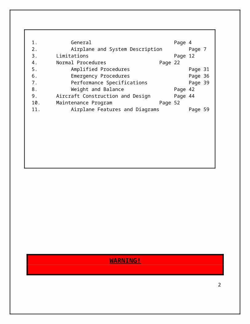
1. General Page 42. Airplane and System Description Page 73. Limitations Page 124. Normal Procedures Page 225. Amplified Procedures Page 316. Emergency Procedures Page 367. Performance Specifications Page 398. Weight and Balance Page 429. Aircraft Construction and Design Page 4410. Maintenance Program Page 5211. Airplane Features and Diagrams Page 59
WARNING!
THE OWNER AND OPERATOR MUST UNDERSTAND THAT DUETO INHERENT RISK INVOLVED
IN FLYING AN AIRCRAFT, NO WARRANTY IS MADE ORIMPLIED, OF ANY KIND, AGAINST ACCIDENTS, BODILY INJURY OR DEATH
2

OTHER THAN THOSE, WHICH CANNOT BYLAW BE EXCLUDED.
THE SAFE OPERATION OF THIS AIRCRAFT RESTS WITH YOU,THE PILOT. I BELIEVE THAT IN ORDER TO FLY SAFELY
YOU MUST MATURELY PRACTICE AIRMANSHIP.OPERATIONS OUTSIDE THE RECOMMENDED FLIGHT
ENVELOPE SUCH AS AEROBATIC MANOEVRES OR ERRATICPILOT TECHNIQUE MAY ULTIMATELY PRODUCE EQUIPMENT
FAILURE. YOU ARE REFERRED TO THE OPERATING LIMITATIONS IN THIS MANUAL.
LIKE ANY AIRCRAFT, SAFETY DEPENDS ON A COMBINATIONOF CAREFUL MAINTENANCE
AND YOU’RE ABILITY TO FLY INTELLIGENTLY AND CONSERVATIVELY. I HOPE THAT THIS AIRCRAFT WILL
PROVIDE YOU WITH MANY HOURS OF SAFE ANDENJOYABLE FLYING.
SECTION 1GENERAL
3

INTRODUCTIONThis Pilot Operating Handbook (POH) is designed for maximum utilization as operating guide for the pilot. It includes the material required by the regulations to be furnished to the pilot. It also contains supplemental data supplied by the airplane manufacturer.
This Pilot Operating Handbook is not designed as a substituted for adequate and competent flight instruction, knowledge of current airworthiness directives, applicable air regulations or advisory circulars. It is not intended to be a guide for basic flight instruction or a training manual and should not be used for operational purposes unless kept in a current status.
Assurance that the airplane is in an airworthy condition is the responsibility of the owner. The pilot in command is responsible for determining that the airplane is safe for flight. The pilot is also responsible for maintaining within the operating limitation as outlined by instrument markings, placards, and this Pilot Operating Handbook.
Although the arrangement of this Pilot Operating Handbook is intended to maximize its in-flight capabilities, it should not be used solely as an occasional operating reference. The pilot should study the entire Pilot and operational handling characteristics of the airplane before flight.
The Pilot Operating Handbook has been divided into numbers sections. The limitations and emergency procedures have been place ahead of the normal procedures, performance and other sections to provide easier access to information that maybe required in flight. The “Emergency Procedures” Section is quickly available, to present instant reference. Provisions for the expansion and/or updates to this Pilot Operating Handbook (POH) have been made.
Before flying the aircraft, read and familiarize yourself with this PHO, the Engine Operators Manual and Maintenance Manual.
This pilot’s handbook provides pilots with the information required for the safe and efficient operation of this aircraft.
CERTIFICATION BASISThis aircraft is operating under a SPECIAL CERTIFICATE OF AIRWORTHINESS and classified as “Amateur Built”. See CAR’s 5.3.3
WARNINGS, CAUTIONS AND NOTESThe following definitions apply to warnings, cautions and notes used in the Pilot Operating Handbook.
4

WARNING: Means that the non-observations of the corresponding procedure lead to an immediate degradation of flight safety which could result in loss of life or destruction of equipment.
CAUTION: Means that the non-observation of the corresponding procedure leads to a degradation of flight safety resulting in damage to the equipment.
NOTE: Draws the attention to any item that is important or unusual.
SECTION 2AIRPLANE AND SYSTEMS DESCRIPTION
5

WING SPAN.............................................29 Ft. 9 In. (9.1m) WING AREA.............................................13.4 m2 (144.2 Sq. Ft.)WING CHORD...........................................4 Ft. 10 In. (1.47 m)LENGTH..................................................21 Ft. 10 In. (6.7 m)HEIGHT...................................................8 Ft. 1 In. (2.6 m)HORIZONTAL TAIL SPAN………………………8 Ft. 8 In (2.64 m)HORIZONTAL TAIL AREA……………………….22.2 Sq. Ft. (2.06 Sq. m)WING LOADING.........................................44.8 kg/ m2 (9.2 lbs/s.f.)
6

POWER LOADING…………………………………12.5 LBS/BHP
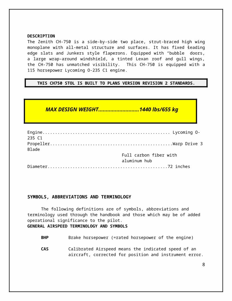
DESCRIPTION The Zenith CH-750 is a side-by-side two place, strut-braced high wing monoplane with all-metal structure and surfaces. It has fixed leading edge slats and Junkers style flaperons. Equipped with “bubble” doors, a large wrap-around windshield, a tinted Lexan roof and gull wings, the CH-750 has unmatched visibility. This CH-750 is equipped with a 115 horsepower Lycoming O-235 C1 engine.
THIS CH750 STOL IS BUILT TO PLANS VERSION REVISION 2 STANDARDS.
MAX DESIGN WEIGHT...........................1440 lbs/655 kg
Engine................................................... Lycoming O-235 C1Propeller.................................................Warp Drive 3 Blade
Full carbon fiber with aluminum hub
Diameter................................................72 inches
SYMBOLS, ABBREVIATIONS AND TERMINOLOGY
The following definitions are of symbols, abbreviations and terminology used through the handbook and those which may be of added operational significance to the pilot.GENERAL AIRSPEED TERMINOLOGY AND SYMBOLS
BHP Brake horsepower (=rated horsepower of the engine)
CAS Calibrated Airspeed means the indicated speed of an aircraft, corrected for position and instrument error. Calibrated airspeed is equal to true airspeed in standard atmosphere at sea level.
GPH Fuel consumption in Gallons (U.S.) per Hour.
KCAS Calibrated Airspeed in “Knots”.
C.G. Centre of Gravity.7
IAS Indicated Airspeed is the speed of an aircraft as shown on the airspeed indicator.
KIAS Indicated Airspeed expressed in “Knots”.
L Left
R RightRPM Revolutions per minute.
S.L. Sea Level
TAS True airspeed is the airspeed of an airplane relative to undisturbed air which the CAS corrected for altitude and temperature.
V Speed
VA Maneuvering Speed is the maximum speed at which the controls may be full (and smoothly) deflected in calm air as long as +4/-2 g is NOT exceeded. Do NOT make full or abrupt control movements above this speed.
VFE Maximum Flap Extended Speed is the highest speedpermissible with wing Flaperons partially or fully extended.
8

SECTION 3LIMITATIONS
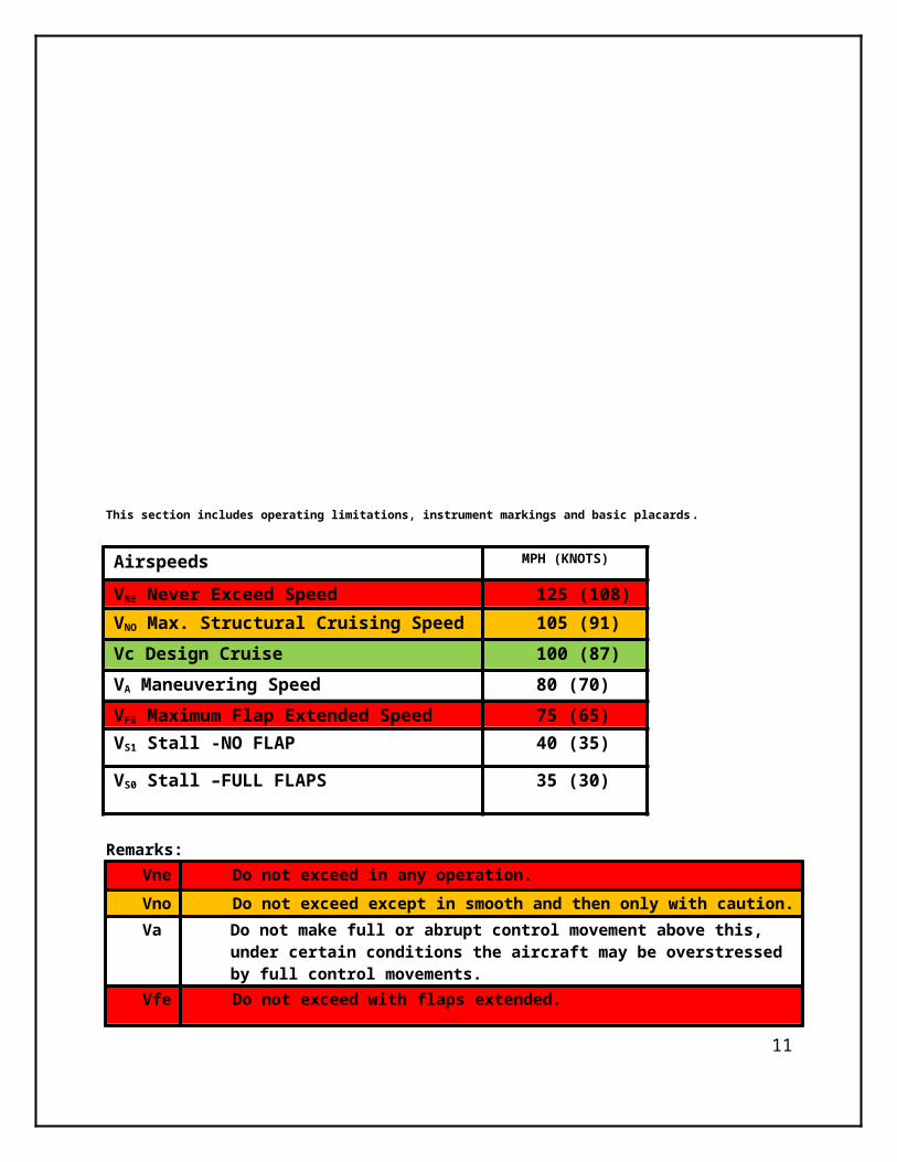
This section includes operating limitations, instrument markings and basic placards.
Airspeeds MPH (KNOTS)
VNE Never Exceed Speed 125 (108)VNO Max. Structural Cruising Speed 105 (91)Vc Design Cruise 100 (87)
9

VA Maneuvering Speed 80 (70)VFE Maximum Flap Extended Speed 75 (65)VS1 Stall -NO FLAP 40 (35)
VS0 Stall –FULL FLAPS 35 (30)
Remarks: Vne
Do not exceed in any operation.
Vno
Do not exceed except in smooth and then only with caution.
Va Do not make full or abrupt control movement above this, under certain conditions the aircraft may be overstressed by full control movements.
Vfe Do not exceed with flaps extended.
Markings: IAS values or ranges:White arc: Vf 35-75 Flap Operating
RangeGreen arc: Vs 40 -105 mph Normal RangeYellow arc: 105-125 mph Caution RangeRed Line: 125 mph Never Exceed Speed
Powerplant:Engine manufacturer..............................LycomingEngine Model.........................................O-235 C1
RATING:Max. continuous horsepower, RPM Sea level pressure altitude 108 HP – 2600 RPM – S.L.
Takeoff (5 min.) HP, at full Throttle 115 HP – 2800 RPM (15 Min. Max)
Fuel (minimum grade aviation)** 80/87 or 100 LL
**NOTE: Automotive Gasoline (MOGas) is approved in this aircraft. It must be Premium fuel only with NO ETHANOL content.
10
Lubricating Oil Lycoming Spec. No. 301-F and ServiceInstructions No. 1014 ***
***NOTE: Lubricants should conform to the specifications as listed or later revisions thereto.
Maximum Power, take-off ...........................115 HPMax continuous: .........................................108 HPMaximum Engine RPM, (15min max)…….......2800 rpm Continuous .................................................2600 rpmMinimum idle ……….......................................600 rpmRecommended idle........................................800 rpmPropeller Drive Ratio…………………………………1:1Propeller Shaft Rotation……………………………ClockwisePropeller shaft end size……………………………Integral flange-SAE Type 2Ignition, timing BTC………………………………25 DegreesOil sump capacity…………………………………6 Quarts*Usable oil……………………………………………4 Quarts*NOTE: To minimize the loss of oil through the breather, fill to 5 quart level for normal flights of less than 3 hours. For extended flight, fill to 6 quarts.
Bore, Inches………………………………………4.375Stroke, Inches……………………………………3.875Displacement, Cubic Inches…………………..233.3Compression Ratio………………………………6.75:1Dry Weight………………………………………..246 lbsCruise Speed – Performance…………………2350Cruise Speed – Economy……………………..2250Fuel Consumption – Economy ……………….6.1 Gal/hrMaximum Cylinder Head Temp……………….500 FMaximum Oil temperature…………………….190-240FSpark Advance…………………………………..25 Degrees BTC
Oil Pressure (PSI) PSINormal 65-85 PSIMaximum 90 PSIMinimum 60 PSIMinimum Idling 25 PSI
Magneto Drop-off, Maximum @ 1800 RPMEach magneto alone……………………125
11

Difference between Magnetos…………35
Magnetos (BENDIX)Right………………………………………S4LN-20Left (impulse)……………………………S4LN-21
Carburetor Marvel-Schebler……………………………………MA-3A
Fuel Pressure Maximum…………………………………8 PSI
Desired……………………………………3 PSIMinimum…………………………………0.5 PSI
Fuel grade Unleaded (MoGAS)…………………91 Octane Ethanol FreeAvgas…………………………………100L
OIL GRADES:*Average Ambient Air MIL-L-6082 Grades
Above 80F (27C) SAE 60Above 60F (16C) SAE 5030F to 90F (-1 – 32C) SAE 30
Below 10F (-12C) SAE 20*NOTE: For simplicity AeroShell 100W can be used in summer and AeroShell 50W used in winter.
Oil Consumption Maximums
0.06 l per hour0.80 Quarts/hr
CHARACTERISICS OF THE LYCOMING O-235 C1: Four cylinder, horizontally opposed, air cooled, direct drive. Has provisions for dual pump drives. Eligible for both tractor and pusher type installations.
Propeller manufacturer: Warp Drive 3 blade 72” with nickel plated leading edges
POWERPLANT INSTRUMENT MARKINGS*Minimum limit 600 RPMGreen Arc 1800-2600 RPM
12

Yellow Arc 2600-2800 RPMRed line 2800 RPMNormal operating 1900-2600 RPMOil Temperature 50C-118C (190-245F)
*NOTE: These markings are displayed on MGL Engine Management System (EMS) display and Tachometer. Do not exceed 2600 RPM for more than 5 minutes.
Average Ambient Air
Temperature
Oil Inlet Temperature
Desired* Maximum
Above 60F (16C) 180F (82C) 245F (118C)30-90F (-1 to 32C) 180F (82C) 245F (118C)0-70F (-18 to 21C) 170F (77C) 245F (118C)Below 10F (-12C) 160F (71C) 245F (118C)
*NOTE: Engine oil temperature should not be below 140F (60C) during continuous operation.
OTHER LIMITS:Cyl. head temp. 260C (500F) max
Fuel pressure 2–5 PSI (Min. 0.5)
Fuel and Oil Consumption:Operation RPM HP Fuel Cons.
Gal./Hr.Max OilGal.Hr.
Max Cylinder
Head Temp
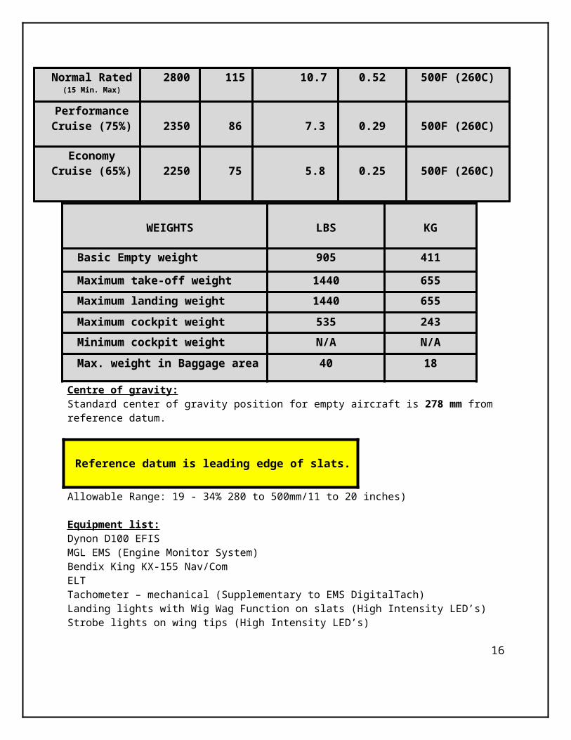
Normal Rated(15 Min. Max)
2800 115 10.7 0.52 500F (260C)
PerformanceCruise (75%) 2350 86 7.3 0.29 500F (260C)
13

EconomyCruise (65%) 2250 75 5.8 0.25 500F (260C)
Centre of gravity:Standard center of gravity position for empty aircraft is 278 mm from reference datum.
Reference datum is leading edge of slats.
Allowable Range: 19 - 34% 280 to 500mm/11 to 20 inches)
Equipment list:Dynon D100 EFISMGL EMS (Engine Monitor System)Bendix King KX-155 Nav/ComELTTachometer – mechanical (Supplementary to EMS DigitalTach)Landing lights with Wig Wag Function on slats (High Intensity LED’s)Strobe lights on wing tips (High Intensity LED’s)Navigation lights on wing tips (High Intensity LED’s)
Maneuvers:
No aerobatics maneuvers including intentional spinning are permitted!
14
WEIGHTS LBS KG
Basic Empty weight 905 411
Maximum take-off weight 1440 655Maximum landing weight 1440 655Maximum cockpit weight 535 243Minimum cockpit weight N/A N/AMax. weight in Baggage area 40 18

Maneuvering load factors:Limit load factor: + 6g / -3g**NOTE: The ultimate load factors are the limit-load factors multiplied by the safety factor of 1.5.
Flight crew:Minimum number of crew members is 1 and maximum total number of occupants is 2
This airplane may be operated in day and night VFR in non-icing condition.
Fuel:Total capacity………………………………………………30 Gallons/112 Lt Usable fuel…………………………………………………..28 Gallons/106 Lt Unusable fuel………………………………………………2 Gallon/8 Lt
APPROVED FUELS:
91 Premium Unleaded NO ETHANOL!100 LL Avgas
Tires:Main - Carlisle 800-6 20psiNose - Carlisle 800-6 20psiLimitation placards*:
Never-exceed speed 125 MPHManeuvering Speed 80 MPHMaximum speed flaps extended
75 MPH
Maximum Engine RPM (Take-Off)
2800 RPM
Max Continuous RPM 2600 RPMMax. Cylinder Head Temperature 260C/500F
Maximum Oil temperature 118C/245F*NOTE: The following limitation placards are placed inside the cockpit
NO LOOSE ITEMS ARE PERMITTED IN CABIN!
15
SECTON 4NORMAL PROCEDURES
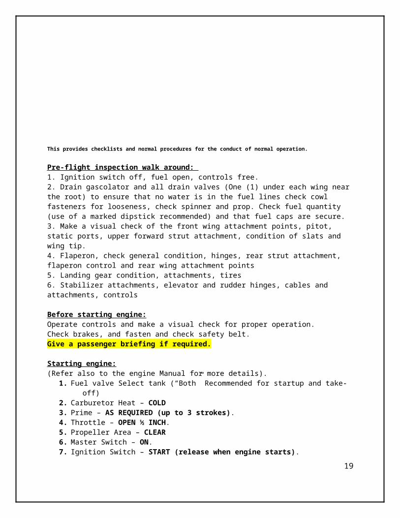
This provides checklists and normal procedures for the conduct of normal operation.
Pre-flight inspection walk around: 1. Ignition switch off, fuel open, controls free.2. Drain gascolator and all drain valves (One (1) under each wing near the root) to ensure that no water is in the fuel lines check cowl fasteners for looseness, check spinner and prop. Check fuel quantity (use of a marked dipstick recommended) and that fuel caps are secure.3. Make a visual check of the front wing attachment points, pitot, static ports, upper forward strut attachment, condition of slats and wing tip. 4. Flaperon, check general condition, hinges, rear strut attachment, flaperon control
16

and rear wing attachment points5. Landing gear condition, attachments, tires6. Stabilizer attachments, elevator and rudder hinges, cables and attachments, controls
Before starting engine:Operate controls and make a visual check for proper operation. Check brakes, and fasten and check safety belt.Give a passenger briefing if required.
Starting engine:(Refer also to the engine Manual for more details).
1. Fuel valve Select tank (“Both” Recommended for startup and take-off)2. Carburetor Heat – COLD3. Prime – AS REQUIRED (up to 3 strokes).4. Throttle – OPEN ½ INCH.5. Propeller Area – CLEAR6. Master Switch – ON.7. Ignition Switch – START (release when engine starts).8. Throttle – Adjust for 1000 RPM or less.9. Warm-Up Engine until Oil Temperature Rises, Take off When Temperature is
Green (140F (60C) recommended).NOTES : Starter limit Max 10sec. Cool 2 min -Check oil pressure rise within 20-30 sec. after start. -Do not increase RPM before verifying oil pressure rise.
- When oil pressure is confirmed warmup engine at approximately800-1000 RPM to prevent plug fouling. Use aggressive mixture leaning as well for ground runs.
BEFORE TAKEOFF
1. Brakes – ON2. Cabin Doors – CLOSED and LATCHED.3. Seat Belts - FASTEN4. Flight Controls – FREE and CORRECT.5. Flight Instrument – SET.6. Fuel Shutoff Valve – SELECT TANK.7. Mixture – FULL RICH (below 3000 feet).8. Elevator Trim – TAKEOFF9. Throttle – 1600 RPM (once engine oil temp has hit 100F min.)
a. Magnetos – CHECK (RPM drop should not exceed 125 RPM on either magneto or 50 RPM differential between magnetos).
b. Carburetor Heat – CHECK (for RPM drop).c. Engine Instruments and Volts – CHECK.
10.Flaps – As Required.11.Radios – SET.12.Altimeter – SET.13.Beacon, Nav. Lights, WIG-WAGs and Strobes - As Required 14.Throttle Friction Lock – Adjust.15.Brakes – RELEASE.
17

Taxiing:
With the tricycle configuration taxiing is facilitated by the use of a steerable nose wheel. Avoid steering the aircraft with the brakes. When winds exceed 20 to 30 mph, taxi very slowly prevent inadvertent lift-off.
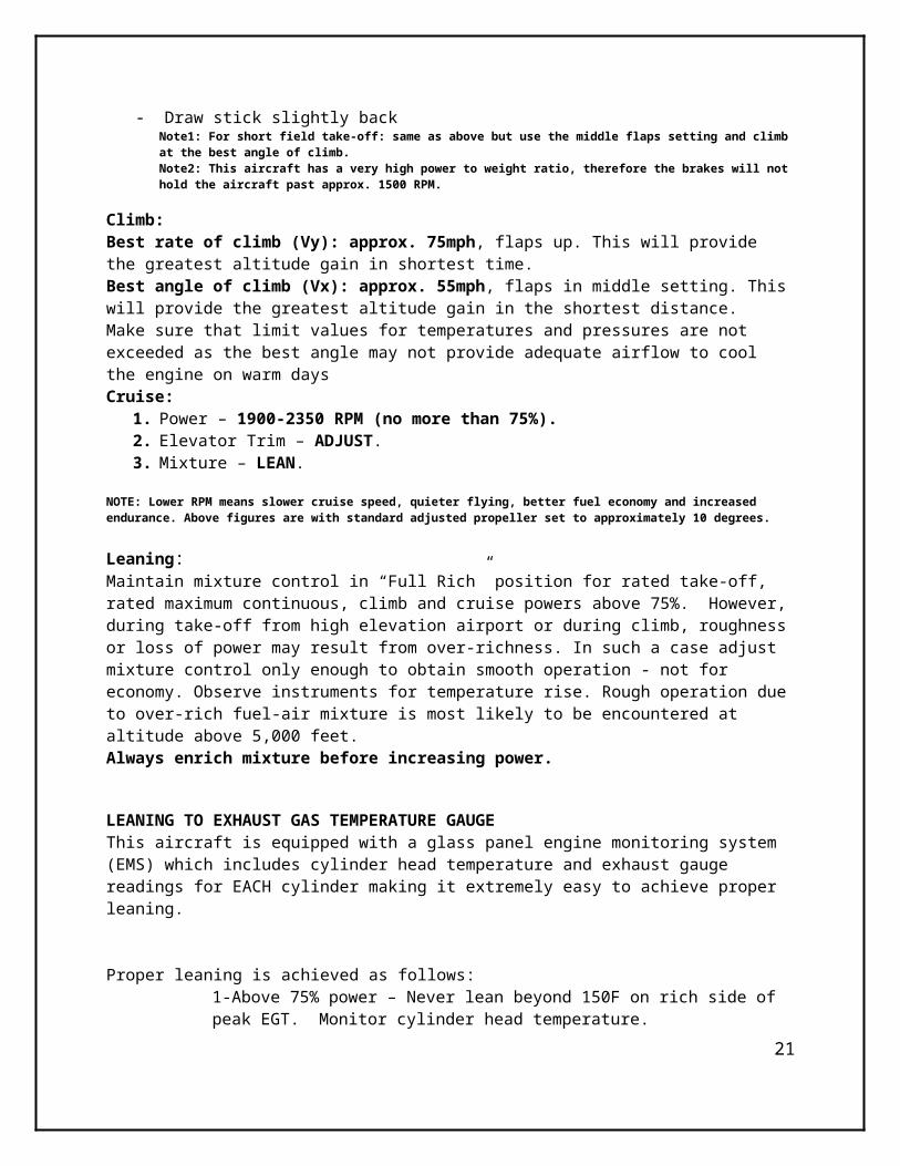
Take off: - Advance throttle smoothly to full - Check RPM and gauges - Release brakes - Draw stick slightly back
Note1: For short field take-off: same as above but use the middle flaps setting and climb at the best angle of climb.Note2: This aircraft has a very high power to weight ratio, therefore the brakes will not hold the aircraft past approx. 1500 RPM.
Climb:Best rate of climb (Vy): approx. 75mph, flaps up. This will provide the greatest altitude gain in shortest time.Best angle of climb (Vx): approx. 55mph, flaps in middle setting. This will provide the greatest altitude gain in the shortest distance.Make sure that limit values for temperatures and pressures are not exceeded as the best angle may not provide adequate airflow to cool the engine on warm daysCruise:
1. Power – 1900-2350 RPM (no more than 75%).2. Elevator Trim – ADJUST.3. Mixture – LEAN.
NOTE: Lower RPM means slower cruise speed, quieter flying, better fuel economy and increased endurance. Above figures are with standard adjusted propeller set to approximately 10 degrees.
Leaning:Maintain mixture control in “Full Rich” position for rated take-off, rated maximum continuous, climb and cruise powers above 75%. However, during take-off from high elevation airport or during climb, roughness or loss of power may result from over-richness. In such a case adjust mixture control only enough to obtain smooth operation - not for economy. Observe instruments for temperature rise. Rough operation due to over-rich fuel-air mixture is most likely to be encountered at altitude above 5,000 feet.Always enrich mixture before increasing power.
LEANING TO EXHAUST GAS TEMPERATURE GAUGEThis aircraft is equipped with a glass panel engine monitoring system (EMS) which includes cylinder head temperature and exhaust gauge readings for EACH cylinder making it extremely easy to achieve proper leaning.
Proper leaning is achieved as follows:18
1-Above 75% power – Never lean beyond 150F on rich side of peak EGT. Monitor cylinder head temperature.2- 75% power and below – Operate at peak EGT.
DO NOT LEAN A CARBURETOR CONTROLED ENGINE LEAN OF PEAK!!!
Leaning may be done at any altitude that the engine will accept leaning: The greater the altitude the more important leaning becomes. Proper leaning is important because more engine power and increased air speed are obtained along with decreased fuel consumption, longer spark plug life, less lead fouling, and more normal oil and cylinder head temperatures. Engine damage from leaning the mixture does not occur at the specified cruise power for the model engine is a basically healthy power plant, but is the result of improper leaning at power settings above recommended cruise.
Carb Heat Control:Under certain moist atmospheric condition, it is possible for ice to form in the induction system even in summer weather. This is due to the height air velocity through the carburetor venture and the absorption of heat from this air by vaporization of the fuel. The temperature in the mixture chamber may drop 20F. to 70F. below the temperature of the incoming air. If this air contains a large amount of moisture the cooling process will cause precipitation in the form of ice. These ice formations generally begin in the vicinity of the butterfly and will often build up to such an extent that a drop in manifold power output results. This loss of power is reflected by a drop in RPM. If not detected, this condition will continue to such an extent that the reduced power will cause complete engine stoppage.
To avoid this condition, this aircraft is equipped with a system for preheating the incoming air supply to the carburetor. In this way, sufficient heat is added to replace the heat loss to vaporization of fuel, and the mixing chamber’s temperature cannot drop to the freezing point of water. This air preheat is essentially a tube or jacket through which the exhaust pipe from one or more cylinders is passed, and the air flowing over these surfaces is raised to the required temperatures before entering the carburetor. Consistently high temperatures are to be avoided because of the loss of power and a decided variation of the mixture. High charge temperatures also favor detonation and pre-ignition, both of which are to be avoided if normal service life is to be expected from the engine. The following outline is the proper method of utilizing the carburetor heat control.
Take-Off:Take off should be made with carburetor heat in full cold position. The possibility of icing at wide throttle opening is very remote.
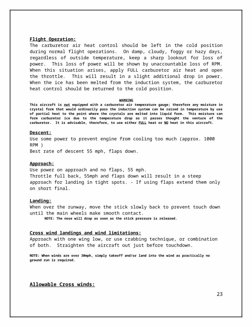
Flight Operation:The carburetor air heat control should be left in the cold position during normal flight operations. On damp, cloudy, foggy or hazy days, regardless of outside temperature, keep a sharp lookout for loss of power. This loss of power will be shown by unaccountable loss of RPM. When this situation arises, apply FULL carburetor air heat and open the throttle. This will result in a slight additional drop in power. When the ice has been melted from the induction system, the carburetor heat control should be returned to the cold position.
19

WARNINGThis aircraft is not equipped with a carburetor air temperature gauge; therefore any moisture in crystal form that would ordinarily pass the induction system can be raised in temperature by use of partial heat to the point where the crystals are melted into liquid form. This moisture can form carburetor ice due to the temperature drop as it passes thought the venture of the carburetor. It is advisable, therefore, to use either FULL heat or NO heat in this aircraft.
Descent:Use some power to prevent engine from cooling too much (approx. 1000 RPM )Best rate of descent 55 mph, flaps down.
Approach:Use power on approach and no flaps, 55 mph.Throttle full back, 55mph and flaps down will result in a steep approach for landing in tight spots. - If using flaps extend them only on short final.
Landing:When over the runway, move the stick slowly back to prevent touch down until the main wheels make smooth contact.
NOTE: The nose will drop as soon as the stick pressure is released.
Cross wind landings and wind limitations:Approach with one wing low, or use crabbing technique, or combination of both. Straighten the aircraft out just before touchdown. NOTE: When winds are over 30mph, simply takeoff and/or land into the wind as practically no ground run is required.
Allowable Cross winds: Wind angle Max Cross Wind Component
900 8 mph 600 10 mph 450 12 mph 300 20 mph
NOTE: With Stall Speed flaps up = 40mph:
Missed landings:Apply full power.Flaps up when speed is above 55 mph.
Shut down:20
After normal flight and taxing, engine should be cold enough to turn it off. If the engine is hot, let it idle to cool. Idle engine at approximately 800-1000 RPM (1000 Recommended to prevent spark plug lead fouling) until there is a decided drop in cylinder head temperature.
1. Parking Brake – SET.2. Radios, Electrical Equipment – OFF.3. Mixture – IDLE CUT-OFF (pull full out).4. Ignition Switch – OFF.5. Master Switch – OFF.6. Control Lock – INSTALL.
WARNING: Do not allow passenger to exit until prop is fully stopped.Tie down:When the aircraft is not in use, tie it down using tie down holes under outboard wing and at the rear fuselage tie down ring. Tie down with the stick forward. Make sure the doors are properly latched.
SECTION 5 AMPLIFIED PROCEDURES
21

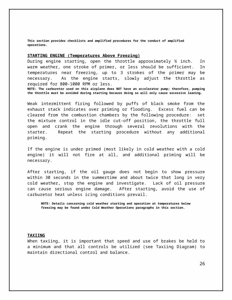
This section provides checklists and amplified procedures for the conduct of amplified operations.
STARTING ENGINE (Temperatures Above Freezing)During engine starting, open the throttle approximately ½ inch. In warm weather, one stroke of primer, or less should be sufficient. In temperatures near freezing, up to 3 strokes of the primer may be necessary. As the engine starts, slowly adjust the throttle as required for 800-1000 RPM or less.NOTE: The carburetor used on this airplane does NOT have an accelerator pump; therefore, pumping the throttle must be avoided during starting because doing so will only cause excessive leaning.
Weak intermittent firing followed by puffs of black smoke from the exhaust stack indicates over priming or flooding. Excess fuel can be cleared from the combustion chambers by the following procedure: set the mixture control in the idle cut-off position, the throttle full open and crank the engine through several revolutions with the starter. Repeat the starting procedure without any additional priming.
If the engine is under primed (most likely in cold weather with a cold engine) it will not fire at all, and additional priming will be necessary.
After starting, if the oil gauge does not begin to show pressure within 30 seconds in the summertime and about twice that long in very cold weather, stop the engine and investigate. Lack of oil pressure can cause serious engine damage. After starting, avoid the use of carburetor heat unless icing conditions prevail.
NOTE: Details concerning cold weather starting and operation at temperatures below freezing may be found under Cold Weather Operations paragraphs in this section.
TAXIINGWhen taxiing, it is important that speed and use of brakes be held to a minimum and that all controls be utilized (see Taxiing Diagram) to maintain directional control and balance.
22
The carburetor heat control knob should be pushed full in during all ground operations unless heat is absolutely necessary. When the knob is pulled out to the heat position, air entering the engine is not filtered.
Taxiing over loose gravel or cinders should be done at low engine speed to avoid abrasion and stone damage to the propeller tips.
The nose wheel is designed to automatically center straight ahead.
BEFORE TAKEOFF
WARM-UPMost of the warm-up will have been conducted during taxi and additional warm-up before takeoff should be restricted to the checklist procedures. Since the engine is closely cowled for efficient in-flight cooling, precautions should be taken to avoid overheating on the ground.
MAGNETO CHECKThe magneto check should be made at 1600 RPM as follows. Move ignition switch first to “R” position and note RPM. Next move switch back to the BOTH to clear the other set of plugs. Then move switch to the “L” position, note RPM and return the switch to the BOTH position. RPM drop should not exceed 125 RPM on either magneto or show greater than 50 RPM differential between the magnetos. If there is a doubt concerning operation of the ignition system, RPM checks at higher engine speeds will usually confirm whether a deficiency exists.
An absence of RPM drop may be an indication of faulty grounding of one side of the ignition system or should be cause for suspicion that the magneto timing is set in advance of the setting specified.
TAKEOFF
POWER CHECKIt is important to check full-throttle engine operation early in the takeoff run. Any sign of rough engine operation or sluggish engine acceleration is good cause for discontinuing the takeoff. If this occurs you are justified in making a thorough full-throttle static runup before another takeoff is attempted. The engine should run smoothly and turn approximately 2280 to 2380 RPM with carburetor heat off and mixture leaned to maximum RPM.
Full throttle runups over loose gravel are especially harmful to propeller tips. When takeoffs must be made over a gravel surface, it is very important that the throttle be advanced slowly. This allows the airplane to start rolling before high RPM is developed, and the gravel will be blown back of the propeller rather than pulled into it. When unavoidable small nicks appear in the propeller blades, they should be immediately corrected using proper techniques for repairing composite propellers.
23

Prior to takeoff from fields above 3000 feet elevation, the mixture should be leaned to give maximum RPM in a full-throttle, static runup.
After full throttle is applied, adjust the throttle friction lock clockwise to prevent the throttle from creeping back from a maximum power position. Similar friction lock adjustment should be made as required in other flight conditions to maintain a fixed throttle setting.
WING FLAP SETTINGSThis aircraft has extreme STOL characteristics. It is very unlikely that flaps will be required for normal usage. Flaps are electrically controlled from the center console via a marked switch. The flaps can be lowered or raised via this switch. There is no indicator showing the position of the flaps on the panel, however the position of the flaps position can easily be determined by looking out the door, directly at the flaperons. It takes approximately 3 seconds to fully extend or retract the flaperons.
SECTION 6EMERGENCY PROCEDURES
24

NOTE: This section provides checklist and amplified procedures for coping with emergencies that may occur. Emergencies caused by airplanes or engine malfunction are extremely rare if proper pre-flight inspections and maintenance are practiced.
Inadvertent opening of Cabin Doors:The primary concern is maintaining control of the aircraft. If a decision is made to close the door in flight establish a safe altitude, trim the aircraft at reduced airspeed and attempt to close the door. Land as soon as safely possible.
Emergency landing:1. Set airspeed for best rate of Descent
65mph flaps up.2. Shut off fuel3. Shut off engine4. Tighten seat belts and harnessNOTE: Avoid tight turns. In some cases, the flaps may be extended before touchdown. Land as usual, straight ahead power-off approach.
Accidental spins:To recover from a spin:
1. Pull throttle to idle position2. Push rudder opposite the spin’s rotation3. Bring the pitch control slightly forward
Fires:
On the ground, before engine is started:1. Keep starter engaged 2. Shut off fuel3. Open throttle full as soon as engine starts to blow the fire out
On the ground, engine running:1. Cabin heat off2. Shut off fuel3. Throttle open to blow fire out
In the air:1. Cabin heat off2. Fuel off3. Ignition off4. Electrics off5. Perform an emergency landing
Do not attempt to restart engine after in-flight fire.
25
Fire in cockpit1. Electrics off2. Cabin heat off3. Use fire extinguisher located in the rear baggage area. Engine restart in flight (after fuel starvation): Fuel Pump ON Fuel Selector “On” (Fullest tank) Engage starter
SECTION 7PERFORMANCE SPECIFICATIONS
26

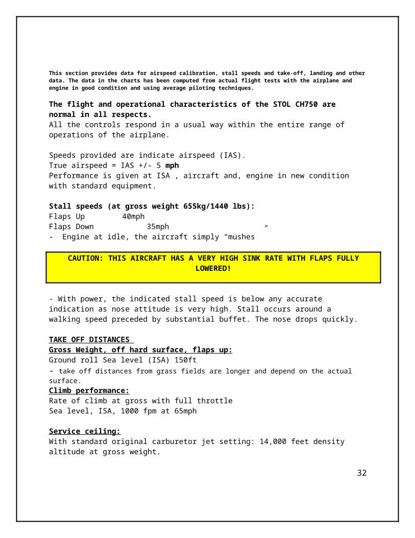
This section provides data for airspeed calibration, stall speeds and take-off, landing and other data. The data in the charts has been computed from actual flight tests with the airplane and engine in good condition and using average piloting techniques.
The flight and operational characteristics of the STOL CH750 are normal in all respects.All the controls respond in a usual way within the entire range of operations of the airplane.
Speeds provided are indicate airspeed (IAS).True airspeed = IAS +/- 5 mph Performance is given at ISA , aircraft and, engine in new condition with standard equipment.
Stall speeds (at gross weight 655kg/1440 lbs):Flaps Up 40mphFlaps Down 35mph- Engine at idle, the aircraft simply “mushes ”
CAUTION: THIS AIRCRAFT HAS A VERY HIGH SINK RATE WITH FLAPS FULLY LOWERED!
- With power, the indicated stall speed is below any accurate indication as nose attitude is very high. Stall occurs around a walking speed preceded by substantial buffet. The nose drops quickly.
TAKE OFF DISTANCES Gross Weight, off hard surface, flaps up : Ground roll Sea level (ISA) 150ft- take off distances from grass fields are longer and depend on the actual surface.Climb performance:Rate of climb at gross with full throttle Sea level, ISA, 1000 fpm at 65mph
Service ceiling : With standard original carburetor jet setting: 14,000 feet density altitude at gross weight.
Best angle of glide : At gross weight with flaps up. 60mph
Fuel consumption: (Lycoming O-235 C1)
2800 RPM (5 Min. Take-off power) 40 lph (10.7 US Gal/hr)
27

2600 RPM (Max continuous) 32 lph (8.5 US Gal/hr)2350 RMP (75% Performance Cruise) 28 lph (7.3 US Gal/hr) 2250 RPM (65% Econony Cruise) 22 lph (5.8 US Gal/hr)
Range and endurance:Engine settings cruise speed at 100 mphPerformance Cruise 75 % power 2350 RPM (includes 2.5 l for T/O)Range (nm)................. 5.9 hrs / 590 smNOTE: Above values are valid for aircraft in good condition and are without reserve. Do not exceed MTOW limit 1440 lbs (655 kgs) while loading the aircraft
SECTION 8WEIGHT AND BALANCE
28

A wide center of gravity range makes loading the Zenith STOL CH 750 easy. Use the graph & table and actual weights to calculate and check that marginal points fall within the permissible range. An excel program has been created which makes calculating the CG extremely easy.These figures must be within the limits for all flying configurations.
Limits C.G. Position: 19 % - 34 % (280mm to 500 mm)
Note, with normal occupants the baggage capacity is not critical for position.
SECTION 9 AIRCRAFT CONSTRUCTION AND DESIGN
29

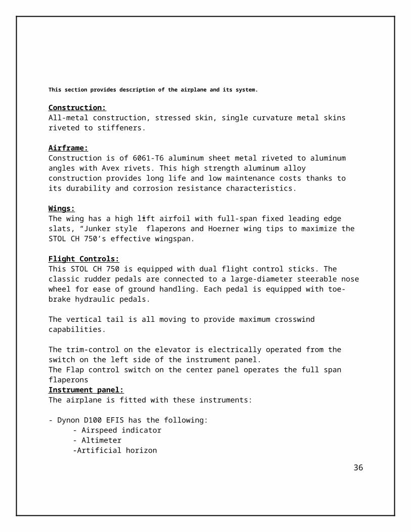
This section provides description of the airplane and its system.
Construction:All-metal construction, stressed skin, single curvature metal skins riveted to stiffeners.
Airframe:Construction is of 6061-T6 aluminum sheet metal riveted to aluminum angles with Avex rivets. This high strength aluminum alloy construction provides long life and low maintenance costs thanks to its durability and corrosion resistance characteristics.
Wings:The wing has a high lift airfoil with full-span fixed leading edge slats, “Junker style” flaperons and Hoerner wing tips to maximize the STOL CH 750’s effective wingspan.
Flight Controls: This STOL CH 750 is equipped with dual flight control sticks. The classic rudder pedals are connected to a large-diameter steerable nose wheel for ease of ground handling. Each pedal is equipped with toe-brake hydraulic pedals.
The vertical tail is all moving to provide maximum crosswind capabilities.
30

The trim-control on the elevator is electrically operated from the switch on the left side of the instrument panel.The Flap control switch on the center panel operates the full span flaperonsInstrument panel:The airplane is fitted with these instruments:
- Dynon D100 EFIS has the following: - Airspeed indicator
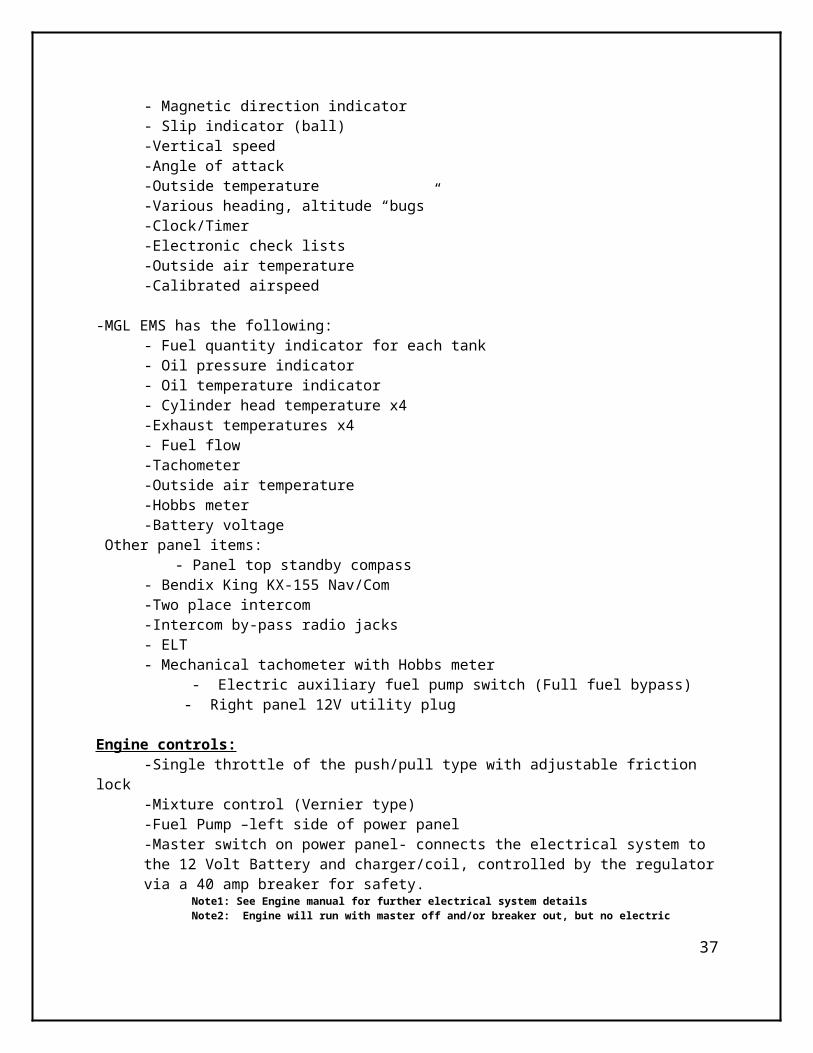
- Altimeter-Artificial horizon- Magnetic direction indicator
- Slip indicator (ball)-Vertical speed-Angle of attack-Outside temperature-Various heading, altitude “bugs”-Clock/Timer-Electronic check lists-Outside air temperature-Calibrated airspeed
-MGL EMS has the following:- Fuel quantity indicator for each tank- Oil pressure indicator- Oil temperature indicator- Cylinder head temperature x4-Exhaust temperatures x4- Fuel flow-Tachometer-Outside air temperature-Hobbs meter-Battery voltage
Other panel items: - Panel top standby compass
- Bendix King KX-155 Nav/Com-Two place intercom-Intercom by-pass radio jacks
- ELT- Mechanical tachometer with Hobbs meter
- Electric auxiliary fuel pump switch (Full fuel bypass) - Right panel 12V utility plug
Engine controls:-Single throttle of the push/pull type with adjustable friction lock-Mixture control (Vernier type)-Fuel Pump –left side of power panel-Master switch on power panel- connects the electrical system to the 12 Volt Battery and charger/coil, controlled by the regulator via a 40 amp breaker for safety.
31
Note1: See Engine manual for further electrical system detailsNote2: Engine will run with master off and/or breaker out, but no electric equipment will operate. Starter will NOT engage with master in “OFF” position!Note3: Starter switch is on the keyed ignition switch on the center console.
Powerplant:Standard powerplant is the Lycoming O-235 C1 4 cylinder, direct drive, air cooled.
Note: Refer to the Lycoming engine manual for detailed description
Electrical System: - 12 V “Earth X” Lithium Iron Phosphate (LiFePO4) battery 36AH on firewall - 14 V engine alternator with 40 Amp capacity - The master switch activates the electrical bus system - All systems get electrical power direct from the battery when Master Switch is ON. -In case of in-flight alternator failure, a warning note illuminates on EMS and the voltage indicator will begin to drop 12 volts. Normal readings are 14.5 – 15 volts depending on current load.
Fuel system:The fuel tank(s) are welded aluminum. The fuel system has two long range 57 ltr (15 Gal) fuel tanks in the wings. Total 114 ltr (30 Gal). Tanks capacity…………………………………Total 114 liter (30 Gal)
NOTE: Usable fuel reduced by 4 ltr (1 Gal) per tank installed.Total useable fuel load Long Range......... Total 102 liter (28 Gal) The fuel tank filler caps are the vented type. The drain valve is situated on the gascolator, located on the right side lower firewall. The tanks have a finger screen filters. The main fuel shut-off valve is located at the center of aircraft on the central console. Options of “Left”, “Right”, “Both” and “OFF”.Fuel tanks are closed in the OFF position. Each fuel tank has one fuel sender indicated on the MGL EMS.
Caution : Proper fuel management requires a visual check of the fuel quantity using a graduated dip stick.
The fuel pump is electrically operated. Fuel pump is located on the cabin floor in front of central firewall area. The fuel pump is NOT required for engine to run or operate, but is recommended on take-off, steep climbs and turns. It can be left on for duration of flight if desired.
There are 3 fuel drain points in the aircraft. One under each tank and one at the gascolator.
Propeller:The Warp- Drive propeller is a high quality, ground adjustable propeller with a 72 inch diameter with standard spinner. The propeller has been set to provide optimum performances for take-off, but pitch can be reset to achieve better climbing or
32

cruising performances. Always refer to propeller manual for instructions. For average pitch, set the propeller to 10.5 degrees. That will provide the max continuous RPM speed of 2250 STATIC RPM. For cruise settings, set the propeller to approximately 12 degrees. That will give a cruise configuration max power of approximately 2100 STATIC RPM. For very fine pitch, set the propeller to 7 degrees, that will give you a static RPM of approximately 2600 STATIC (Max) RPM.
To prevent vibration, it very important that all the blades are set at exactly the same angle and that the blades are properly secured in the hub.For a take-off and climb propeller setting angle be reduced by l/4 to l/2 degree and for a cruise propeller setting increase angle approximately by l/4 degree at a time until the performance wanted is noted. Note that when cruising setting is used, the take-off and climb performance deteriorate.
Landing Gear:The main gear consist of a solid monoblade heat-treated aluminum alloy spring suspension which eliminates all moving parts and is virtually maintenance free. The nose gear uses a bungee shock absorber to provide rough field capabilities.
Cabin doors:Access to the cabin is via large hinged doors on each side. They are secured by a latch system in three locations.This is operated by the door handle. The doors are “Gull” type doors with the hinges at the top.
Seats:Side-by-side seating with 3 point seatbelts. Seats are adjustable fore and aft by use of a spring loaded handle beneath each seat.Note: Prior to each flight, ensure that the seat belts are firmly secured to the airframe and that the belts are not damaged. Adjust the buckle so that it is centered on the body.
Ventilation:Ventilation is provided by the vents in the doors. Push to open and can be spun to direct airflow where desired. Cabin heater has a pull “choke type” control for heat, located on the right side of the panel in front of the passenger heat. Pull on for heat.
Pitot and static pressure systems:The Pitot pressure is provided by the pitot tube located under the left wing. It is a “Dynon” type pitot with a secondary intake for angle of attack measurements.
Note: blowing into the tube will damage the airspeed indicator.
The static pressure is provided by the static ports on the cabin sides, located behind the baggage area. They are marked on the outside fuselage. Both are tied together and provide a “balance” reading of the static pressure. This also provides a safety, should one of the ports becomes clogged, the other will function.
33

The Baggage Compartment : Space provided behind the seat. It holds up to 40 lbs(18 kg) of evenly distributed and properly secured cargo.
NOTE: Limit is based on the structure of the baggage area, not the C.G. of the aircraft!
Optional equipment : Utility Options such as skis, floats, amphibious floats, cargo pods etc. are available from Zenair for variety of uses.Caution: The installation of skis, floats, amphibious floats, or other equipment will change the performance and characteristics of the STOL CH 750.
Documents:Ensure that all required documents are carried on board the aircraft, including: - This flight manual - C of A - C of R - Insurance certificate - Journey Log - Weight & Balance-Pilot’s log book should also be available, but not necessary.
SECTION 10MAINTENANCE PROGRAM
34

Aircraft handling, servicing & maintenance
This section contains factory-recommended procedures for proper ground handling and servicing of the airplane. It also identifies certain inspection and maintenance requirement which must be followed if the airplane is to retain that new-plane performance and dependability. Follow a planned schedule of lubrication and preventive maintenance based on climatic and flying conditions encountered. Always handle the aircraft with care.
DO NOT PUSH ON ANY CONTROL SURFACE. THIS INCLUDES STABILIZER.
To push the tail down, push down on the rear fuselage, just ahead of the vertical fin. Press down on longeron area ONLY, not on the skin.
DO NOT PUSH OR PULL AT THE CENTER OF THE STRUTS TO MOVE THE AIRCRAFT AS BENT STRUTS WILL RESULT!
Pushing or pulling is acceptable on the gear and at the bottom and top of the struts (close to their attachment points).
As the STOL CH 750 is an all metal aircraft built from high strength aviation grade aluminum alloys which have good corrosion resistant characteristics, little care to the airframe is required, even when stored outside.A cup of dishwater liquid in a pail of water will help remove unwanted dirt. Always rinse thoroughly with fresh water after washing.
The following maintenance program outlines the minimal maintenance which must be followed to keep the aircraft in good flying condition. The suggested time interval of 25 hour does not in any sense eliminate the need for routine maintenance before and after each flight. Maintenance is part of the pilot’s responsibility: the pilot should assure that the aircraft is airworthy at all times. The recommended 25 and 100 hour maintenance checks are designed to cover areas frequently neglected in the quicker preflight
35
inspection and serve only as a useful indication of the required maintenance.Record all maintenance and repairs in the Aircraft Technical Log Book.Aircraft servicing and maintenance should be performed by a qualified individual.
Every 25 hours
Check the general condition of the aircraft and in particular the following:
- General: Verify that no cables are chafed, check for proper anchorage and attachment of all items (fuel and oil lines, electrics, etc.). Verify that all fasteners and pins have the required safety.
- Controls: Check for rust on steel parts (clean and repaint as required). Lubricate all moving parts (hinges, control attachments, bearings, etc.). Verify that all controls operate smoothly and that they are firmly attached.
- Landing gear: inspect nose gear, stops, bungee, control and inspect the main spring, wheel forks and axles.- Wheels: for correct tire pressure. Check the tire wear, rims, and braking system and lines- Cabin interior: Clean with household cleaners according to the materials. - Windshield and windows: The windshield is a single piece of polycarbonate plastic, highly resistant to impact. Clean with “Windex” the polycarbonate will craze with most chemicals. Do not use gasoline, alcohol, oil, lacquer, benzene, paint thinner, etc..... - Propeller: Check the tips and leading edges for damage. Look for nicks and cracks. Inspect spinner, bolts (tight and secured). Wiping the propeller with a slightly oily cloth will result in cleaning off grass and bug, stains. - Engine compartment: Thoroughly check and inspect the engine compartment, including the reduction gear unit, exhaust system, fuel system, oil system and coolant system.-Clean (replace if required) the carburetor air filter.The engine and compartment should be kept free of any accumulation of oil, grass and dirt to prevent a fire hazard. - Engine: Refer to engine manual - follow the procedures recommended by Lycoming.- Engine cowling: Check for looseness, Dzus fasteners, front pins and any damage or cracks.Make sure it is properly secured.- Fuel: Remove, clean, and re-install gascolator. Inspect for any leaks and loose fittings in the lines and tank(s), and assure the smooth operation of shut-off valves. Clean (or replace) any installed filters.
Every 100 hour or annual (whichever comes first)
Clean the aircraft: exterior and interior. Open the rear fuselage bottom access door.Make a thorough inspection of the whole aircraft, inspecting for any damage, wear or corrosion.
36
Front of aircraft: Check and inspect the following: Engine (see engine manual), controls and hoses, engine mount, propeller, battery, exhaust, firewall, nose gear and wheel. Check that all bolts and nuts are tight and safetied.
Fuel system: Check for leaks, check condition and safety of lines and valve operation.Clean, re-install (or replace) and secure all filters, gascolator and tank finger screen.
Fuselage: Check skins and internal structure for loose rivets, bolts, corrosion and buckling due to miss-handling or over-stressing. Check that the drain holes in the bottom of the fuselage are not plugged up.
Controls: Inspect for looseness, wear, fair-leads and terminals.
Wing & Struts: Check skins, replace loose rivets, check for corrosion and buckles (from mishandling), inspect leading edges and trailing edges. Check bolts and safety (struts, jury struts, wing root attachments, slats and flaperons). Check control surface stops and flaperon interconnection.
Tail: Inspect skins and rivets and look for and correct corrosion etc. Check attachment of tail sections to fuselage, cable ends, trim tab, etc. Check control surface stops.Landing gear: Refer to 25 hour check list.After the thorough inspection of the aircraft, and after having done the required maintenance and/or repairs,close the rear fuselage access door and run the engine checking for smooth operation. Check all control hinges and moving parts for wear.Replace when clearance exceeds maximum wear of 0.6 mm.
Oil the following using standard “motor” oil.-all bearings-all flaperon hinge points-all flaperon control rods *-roll control torque tube *-elevator and trim (trim + control)-all rudder hinge points-all elevator bellcranks * -flaperon mixer * -all pitch control rod ends * -all control stick bearings (in cabin)-pedals (3 bearings, cable ends, brake pedals)-flaperon and trim controls-all cable ends *-all throttle bearings-Mixture control-all door hinges and latches * inside fuselage - access through fuselage bottom door.-Grease (with bearing grease): the nose gear strut (top and bottom bearing) and nose wheel axle, and grease all cable fairleads.
37

-Main gear spring attachment.. Check that the rubber pads are undamaged and properly secured in place (check top and bottom, right and left sides).
-After having made a hard landing: Check the wheel forks (especially if landing was in crosswind), they may be bent sideways. Check the main gear spring, forks, wheels, nose gear strut attachments top and bottom.
Note: ALWAYS refer to the STOL CH 750 Plans and Manuals, and Engine manual(s) before effecting repairs or replacing parts. ALWAYS use approved replacement parts.Rivet replacement: Drill out loose or corroded blind rivets and replace using Avex rivets.If required, replace with a rivet the next size up. and/or add another rivet at approximately 12 mm center distance..Cracked sheet metal: If a small crack appears, stop the crack by drilling a small (3.2 mm) hole at the end of crack. If the crack grows again add a patch of the same thickness material and rivet all around with AVEX A4 rivets at a maximum pitch of 40 mm. Do not damage internal structure when drilling. Buckled trailing edges (due to mishandling): They are usually not detrimental to the strength of the aircraft, as long as the buckle does not exceed 15 mm over 1 m. They may slightly off-set the correct trimming in flight. Check for cracks which may develop.
38

SECTION 11FEATURES AND DIAGRAMS
Interior Dimensions
39

Design Features
Overall Dimensions
40

41