apic - university of albertaapic/uploads/forum/p2.pdf · apic power & energy consortium scada,...
TRANSCRIPT
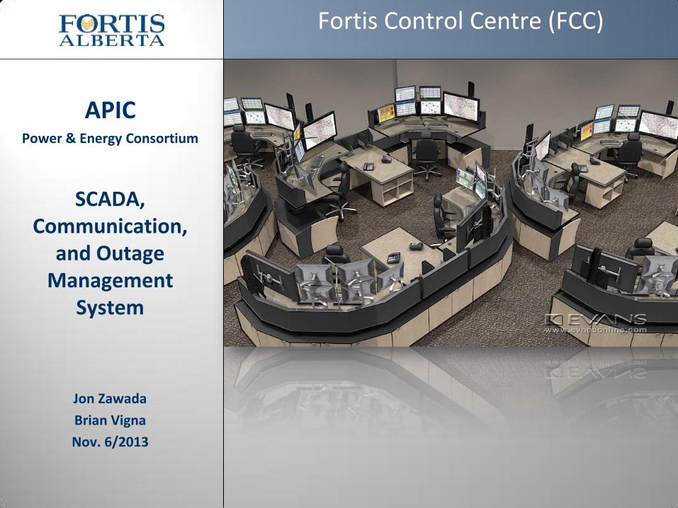
APIC Power & Energy Consortium
SCADA, Communication,
and Outage Management
System
Jon Zawada
Brian Vigna
Nov. 6/2013
Fortis Control Centre (FCC)
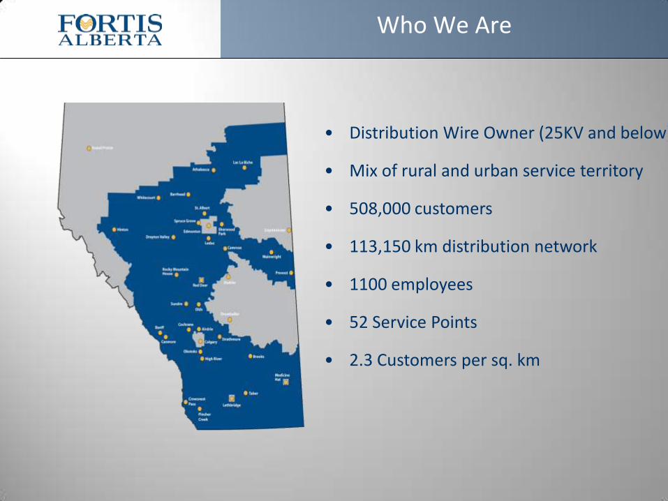
• Distribution Wire Owner (25KV and below)
• Mix of rural and urban service territory
• 508,000 customers
• 113,150 km distribution network
• 1100 employees
• 52 Service Points
• 2.3 Customers per sq. km
Who We Are
Outage Management System (OMS)
OMS Principles and Integration Requirements
• GIS (G Electric) is the source of our OMS Network Model
• CIS (SAP) provides the customer information
• OMS Trouble Analysis predicts tripped device by analyzing network model and incoming data (SCADA/ CIS/IVR)
• Dispatch to Crews using IMobile - Switch #/ Cust Count/ Phase(s)
3
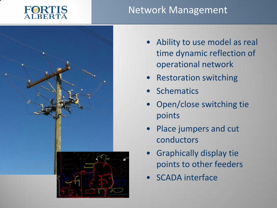
Network Management
• Ability to use model as real time dynamic reflection of operational network
• Restoration switching
• Schematics
• Open/close switching tie points
• Place jumpers and cut conductors
• Graphically display tie points to other feeders
• SCADA interface
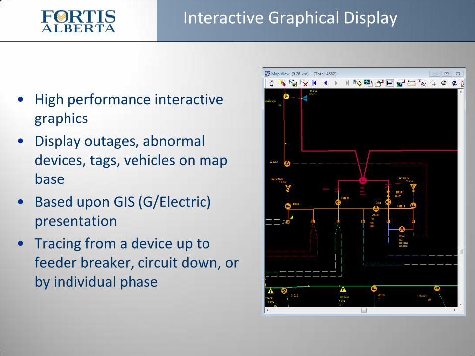
Interactive Graphical Display
• High performance interactive graphics
• Display outages, abnormal devices, tags, vehicles on map base
• Based upon GIS (G/Electric) presentation
• Tracing from a device up to feeder breaker, circuit down, or by individual phase
– 6 –
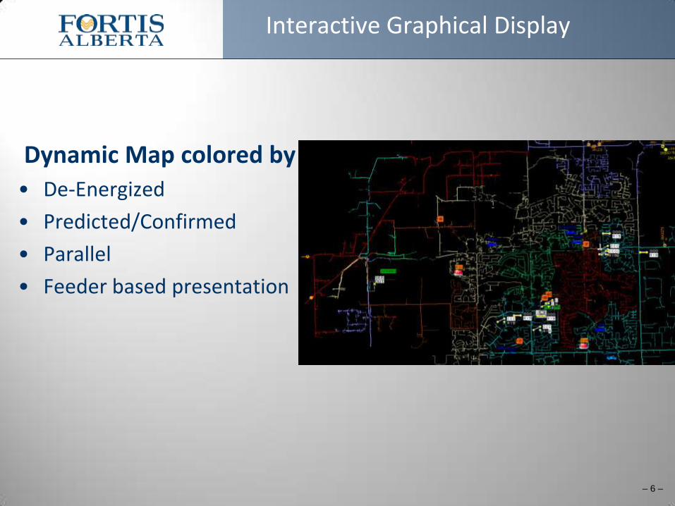
Interactive Graphical Display
Dynamic Map colored by
• De-Energized
• Predicted/Confirmed
• Parallel
• Feeder based presentation
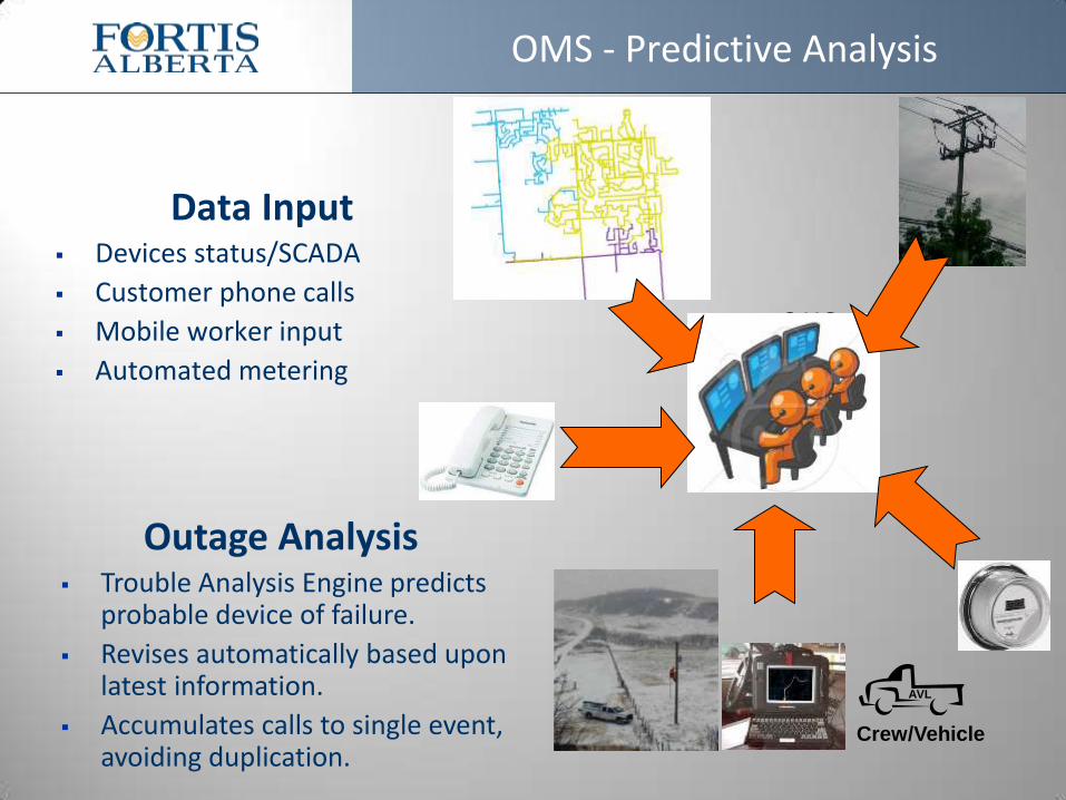
OMS - Predictive Analysis
Data Input Devices status/SCADA
Customer phone calls
Mobile worker input
Automated metering
Outage Analysis Trouble Analysis Engine predicts
probable device of failure.
Revises automatically based upon latest information.
Accumulates calls to single event, avoiding duplication.
OMS
Crew/Vehicle
AVL
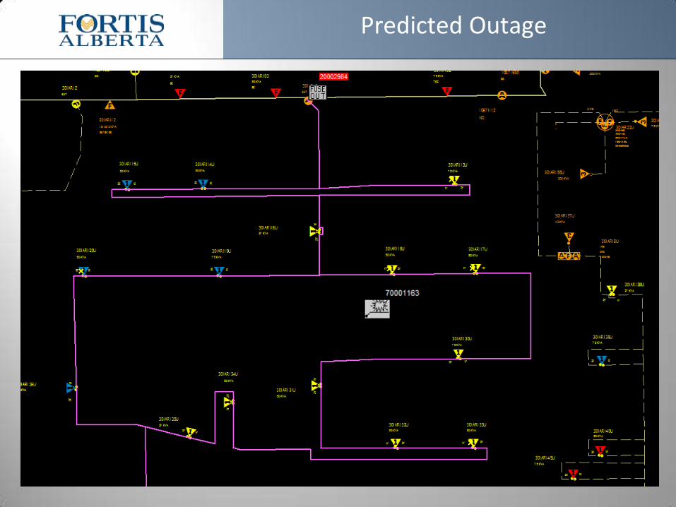
Predicted Outage
8
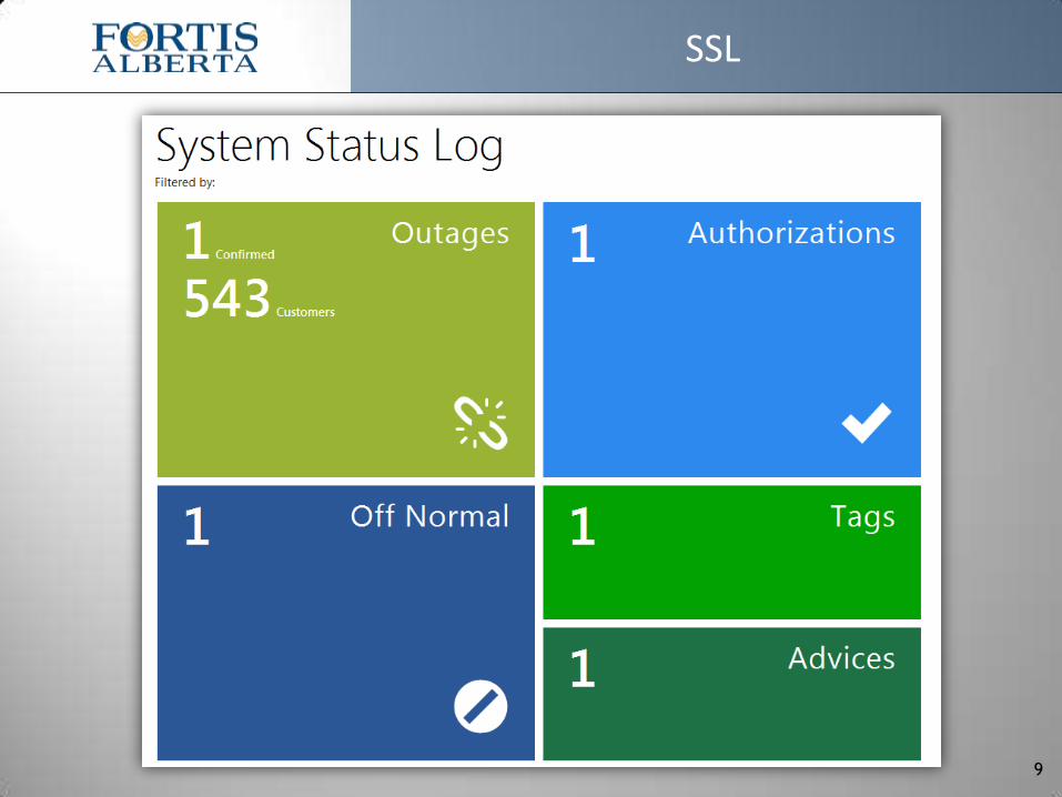
SSL
9
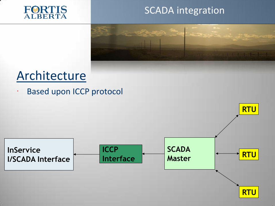
Architecture Based upon ICCP protocol
SCADA integration
InService
I/SCADA Interface
ICCP
Interface
SCADA
Master
RTU
RTU
RTU
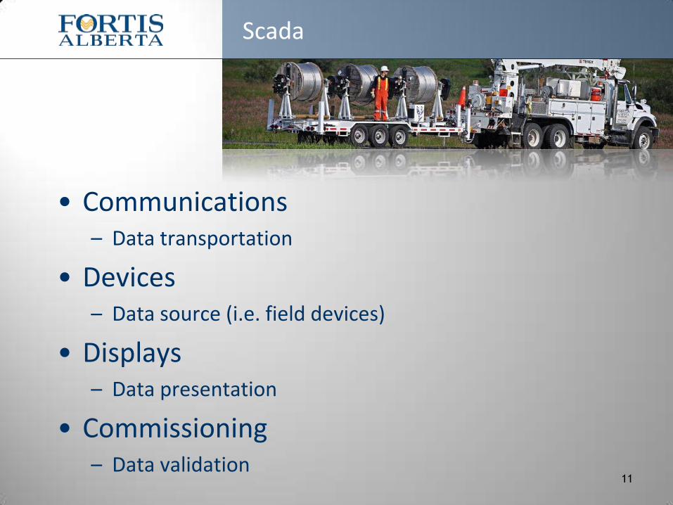
• Communications – Data transportation
• Devices – Data source (i.e. field devices)
• Displays – Data presentation
• Commissioning – Data validation
Scada
11
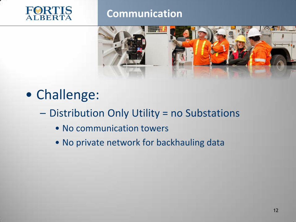
• Challenge: – Distribution Only Utility = no Substations
• No communication towers
• No private network for backhauling data
Communication
12

• Technology used – Mesh Radios (i.e. Ethernet Radios)
• Distribution Automation data backhauled via VPN tunnel within our corporate network
– Cell Modems (i.e. TELUS Mobility)
• Rural Reclosers/switches data backhauled via TELUS MPLS
– Fiber channels
• Data connection between FortisAlberta & AltaLink
Communication
13
• Long range plan: Find alternative to Public Cell Carrier – Monthly data plans will add up as device count
increases
• Create own communication network?
• Create own territory wide UHF radio network?
Communication
14
• Field devices or Intelligent Electronic Devices (IEDs) – Overhead & underground switches
– Overhead reclosers (OCR)
– Underground molded vacuum interrupters (MVI)
• List of available data to pick from – Current, voltage, watts, open/closed, etc.
Field devices or IEDs
15

• Custom data map to minimize data usage
Field devices or IEDs
16
DNP
Index
IED
Index Name Description
0 6 DEVICE_NAME_RELAY Relay Status
1 7 DEVICE_NAME_TRIP Protection Trip Annunciator
2 8 DEVICE_NAME_AC_FAIL AC Failure Annunciator
3 9 DEVICE_NAME_BATT_ALM Battery Alarm Annunciator
4 10 DEVICE_NAME_X_OVERCURRENT X Phase Overcurrent Fault Annunciator
5 11 DEVICE_NAME_Y_OVERCURRENT Y Phase Overcurrent Fault Annunciator
6 12 DEVICE_NAME_Z_OVERCURRENT Z Phase Overcurrent Fault Annunciator
7 13 DEVICE_NAME_GND_OVERCURRENT Ground Overcurrent Fault Annunciator
8 22 DEVICE_NAME_LOCKOUT Recloser Lockout Annunciator
9 148 DEVICE_NAME Device Status
10 288 DEVICE_NAME_GND_TRIP Ground Trip Protection Status
11 289 DEVICE_NAME_RECLOSING Automatic Reclosing Status
12 290 DEVICE_NAME_SUPERVISORY Remote or Local Operation Mode
13 291 DEVICE_NAME_ALT1_SETTINGS Alternate Protection Settings #1 Annunciator
DNP
Index
IED
Index Name Description
0 1 DEVICE_NAME_OPS_COUNTER Operation Counter
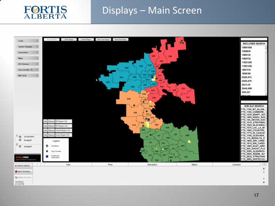
Displays – Main Screen
17
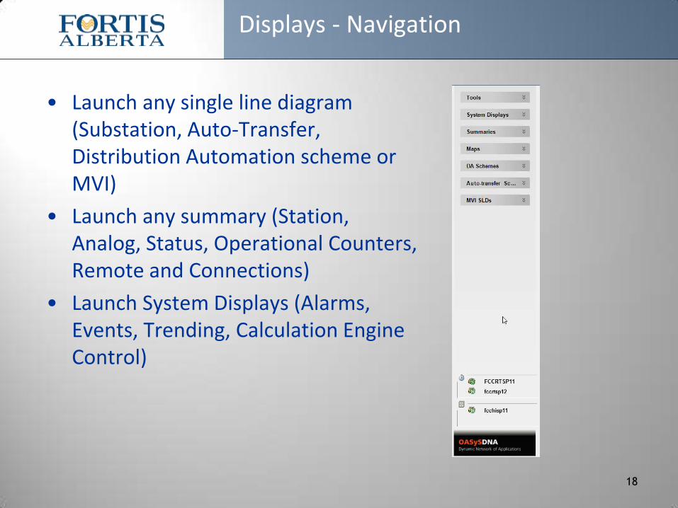
Displays - Navigation
• Launch any single line diagram (Substation, Auto-Transfer, Distribution Automation scheme or MVI)
• Launch any summary (Station, Analog, Status, Operational Counters, Remote and Connections)
• Launch System Displays (Alarms, Events, Trending, Calculation Engine Control)
18

Displays – Main Screen
19
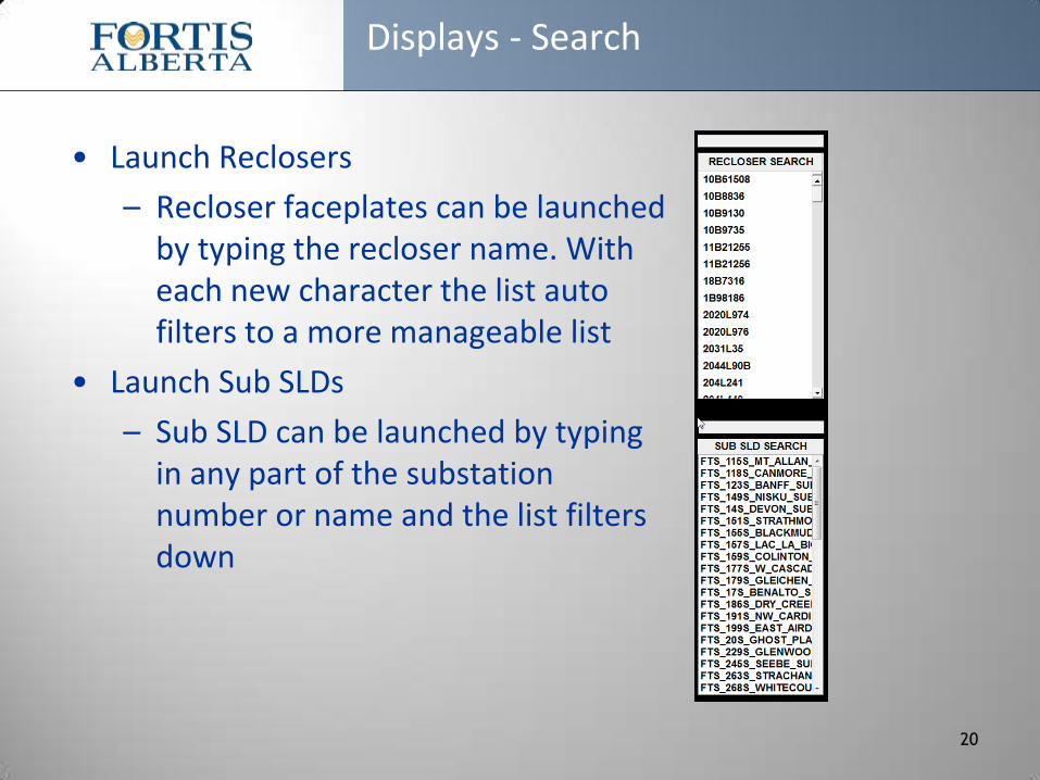
Displays - Search
• Launch Reclosers
– Recloser faceplates can be launched by typing the recloser name. With each new character the list auto filters to a more manageable list
• Launch Sub SLDs
– Sub SLD can be launched by typing in any part of the substation number or name and the list filters down
20
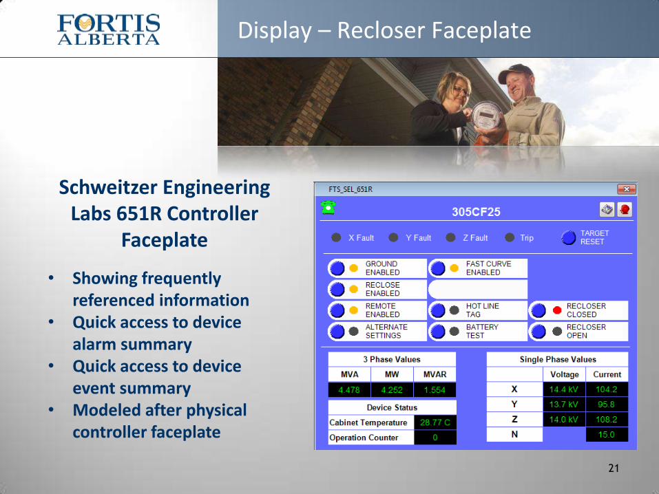
Display – Recloser Faceplate
21
Schweitzer Engineering Labs 651R Controller
Faceplate
• Showing frequently referenced information
• Quick access to device alarm summary
• Quick access to device event summary
• Modeled after physical controller faceplate
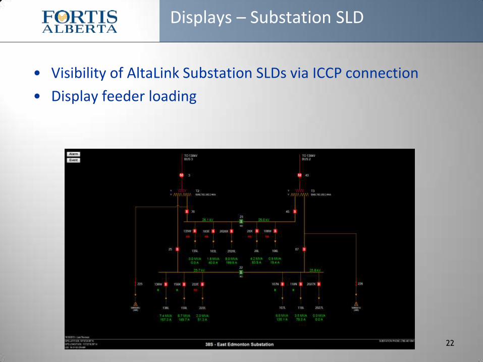
Displays – Substation SLD
• Visibility of AltaLink Substation SLDs via ICCP connection
• Display feeder loading
22
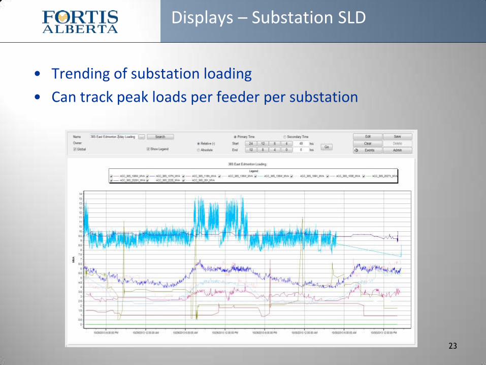
Displays – Substation SLD
• Trending of substation loading
• Can track peak loads per feeder per substation
23

Displays – Main Screen
24
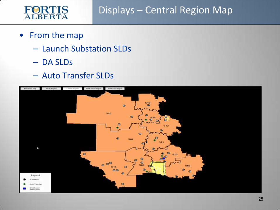
Displays – Central Region Map
• From the map
– Launch Substation SLDs
– DA SLDs
– Auto Transfer SLDs
25
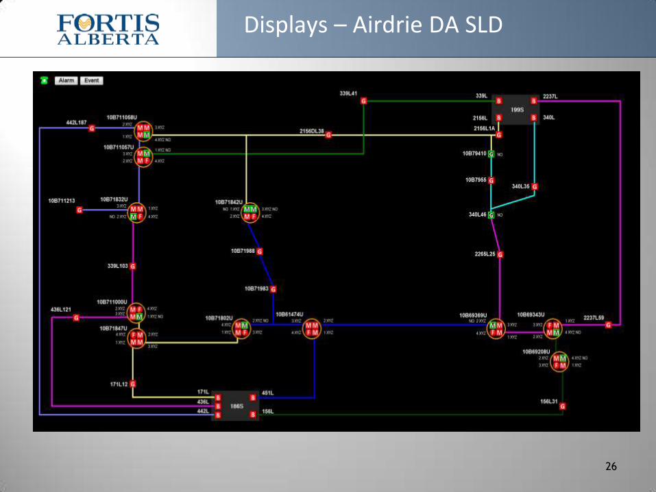
Displays – Airdrie DA SLD
26

Displays – DA Switch Faceplate
• S&C PMH-11 switching cubicle faceplate
– Modeled after the physical controller faceplate
– Future addition of event and alarm summary access pertaining to just this device
– Trying to minimize number of mouse clicks to access information
27
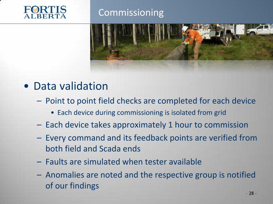
• Data validation – Point to point field checks are completed for each device
• Each device during commissioning is isolated from grid
– Each device takes approximately 1 hour to commission
– Every command and its feedback points are verified from both field and Scada ends
– Faults are simulated when tester available
– Anomalies are noted and the respective group is notified of our findings
Commissioning
– 28 –

Questions?
Questions?
Confidential - not for distribution
29