apegbc technical and practice bulletin...apegbc technical & practice bulletin apegbc revised...
TRANSCRIPT

APEGBC Technical and Practice Bulletin
Structural, Fire Protection and Building Envelope Professional Engineering Services for 5- and 6-Storey
Wood Frame Residential Building Projects (Mid-Rise Buildings)
© April 2009 All Rights Reserved
Revised April 8, 2015

Table of Contents
1.0 INTRODUCTION ................................................................................................................................. 1
1.1 Purpose .................................................................................................................................. 1 1.2 Disclaimer and Exclusion of Liability ...................................................................................... 1 1.3 The Role of APEGBC ............................................................................................................... 2 1.4 Scope of Bulletin .................................................................................................................... 2 1.5 Applicability of Bulletin .......................................................................................................... 2 1.6 Acknowledgements ................................................................................................................ 3 1.7 Introduction of Terms and Abbreviations .............................................................................. 3
2.0 PROFESSIONAL PRACTICE ................................................................................................................. 4
2.1 Coordination .......................................................................................................................... 4
3.0 STRUCTURAL ENGINEERING PRACTICE ISSUES ................................................................................. 5
3.1 Role of the Structural Engineer of Record (SER) .................................................................... 5 3.2 Structural Engineering Services.............................................................................................. 5 3.3 Structural Design Drawing Presentation ................................................................................ 5 3.4 Design Coordination ............................................................................................................... 6 3.5 Design and Detailing of Wood Shearwalls and Diaphragms .................................................. 7 3.6 Design For Building Deformation ........................................................................................... 9 3.7 Fire And Elevator Walls ........................................................................................................ 11 3.8 Hybrid Systems ..................................................................................................................... 13
4.0 FIRE PROTECTION ENGINEERING PRACTICE ISSUES ....................................................................... 15
4.1 Fire Protection Engineering .................................................................................................. 15 4.2 Role of the Fire Protection Engineer (FPE) ........................................................................... 15 4.3 Alternative Solutions and Engineering Judgments .............................................................. 15 4.4 Fire Protection Engineering Design Services ........................................................................ 15 4.5 Effects of Shrinkage .............................................................................................................. 15 4.6 Effects of Differential Lateral Movements ........................................................................... 16 4.7 Firewalls ............................................................................................................................... 16 4.8 Elevator Walls ...................................................................................................................... 17 4.9 Reduced Loading of Fire Rated Assemblies ......................................................................... 18 4.10 Fire Separations ................................................................................................................... 18 4.11 Concealed/Void Spaces ........................................................................................................ 19 4.12 Sprinkler Systems ................................................................................................................. 20 4.13 Firefighting Assumptions ..................................................................................................... 21 4.14 Exterior Cladding .................................................................................................................. 21 4.15 Use of Wood Trim or Other Combustible Components ....................................................... 21 4.16 Soffits and Roof Overhangs .................................................................................................. 22 4.17 Coordination ........................................................................................................................ 22 4.18 Field Review ......................................................................................................................... 22 4.19 Peer Review .......................................................................................................................... 22
5.0 BUILDING ENVELOPE ENGINEERING PRACTICE ISSUES .................................................................. 23
5.1 Role of the Building Envelope Engineer (BEE) ...................................................................... 23 5.2 Building Envelope Engineering Services: Appropriate Professional Practice ...................... 23

5.3 Wood Shrinkage ................................................................................................................... 23 5.4 Change in Environmental Loads – Impact on Building Envelope ......................................... 26 5.5 Impact of Increased Wind and Rain Loads ........................................................................... 26 5.6 Increased Structural Mass .................................................................................................... 28 5.7 Maintenance And Renewal .................................................................................................. 29
6.0 QUALITY ASSURANCE/QUALITY CONTROL...................................................................................... 31
7.0 EDUCATION, TRAINING AND EXPERIENCE ...................................................................................... 33
8.0 REFERENCE AND RELATED DOCUMENTS ........................................................................................ 34
APPENDIX A: MINISTERIAL ORDER ............................................................................................................. 36
APPENDIX B: DEFINITIONS ......................................................................................................................... 41
APPENDIX C: E XAMPLE TOLERANCES ON STRUCTURAL DRAWINGS AND WOOD FRAME SHEARWALLS . 43
APPENDIX D: GUIDELINES FOR PROFESSIONAL PRACTICE FOR A FIRE PROTECTION ENGINEER ............... 45
APPENDIX E: EXAMPLE OF A STRUCTURAL DESIGN FOR A SIX STOREY WOOD FRAME RESIDENTIAL BUILDING .................................................................................................................................................... 61

APEGBC Technical & Practice Bulletin APEGBC Revised April 8, 2015 5 and 6 Storey Wood Frame Residential Building Projects (Mid-Rise)
1
1.0 INTRODUCTION This bulletin provides detailed information on the increased level of complexity involved in engineering considerations which need to be addressed in going from 4 storey to mid-rise building projects. Where relevant, guidance provided in this bulletin is applicable for use on wood frame building projects of 4 storeys or less. Examples of engineering design considerations which affect professional engineering practices in going from 4 storey to mid-rise building projects include:
Increased lateral loads (wind and seismic); Increased environment loads on building envelope assemblies; Increased cumulative effect of wood shrinkage; Increased structural mass of the wood framing affecting such items as glazing and
insulation which, in turn, impact the energy performance of the building; and Enhanced requirements for fire and life safety with respect to building materials and fire
suppression systems. The above examples reinforce the increased need for an enhanced level of coordination of the engineering design between various engineering disciplines and with other design consultants on mid-rise building as compared to that provided on 4 storey building projects of similar construction.
1.1 PURPOSE This bulletin provides basic technical and practice guidance on structural, fire protection and building envelope professional engineering issues related to mid-rise buildings. In the areas identified standards of practice that a Member should follow in providing structural, fire protection and building envelope professional engineering services for these types of building projects are set out. This bulletin has been developed to identify issues to be taken into consideration when providing engineering services on such buildings and to provide sources of information and in some instances, design options. Engineering practices in this area will evolve as codes, standards and guides relevant to these areas of practice are updated and revised to reflect a change to the BCBC permitting five and six storey wood frame residential construction. Refer to Section 1.4 of this bulletin for the scope of building projects to which this bulletin applies. It is anticipated that as experience is gained in the design and construction of mid-rise building projects, it may prove necessary to update this bulletin. On this basis, all those using this bulletin are advised to obtain the most current version. This bulletin may also be referred to by other design professionals such as architects and other parties such as land owners, developers, approving officers, building inspectors, contractors, municipalities, regional districts and the general public.
1.2 DISCLAIMER AND EXCLUSION OF LIABILITY This document is provided without any representations, warranties, or conditions or any kind, express or implied, including, without limitation, implied warranties or conditions concerning this document’s fitness for a particular purpose or use, its merchantability, or its non-infringement of any third party’s intellectual property rights. APEGBC does not warrant the accuracy, completeness, or currency of any of the information published in this document. APEGBC makes no representations or warranties regarding this document’s compliance with any applicable statute, rule or regulation. IN NO EVENT SHALL APEGBC, ITS VOLUNTEERS, MEMBERS SUBSIDIARIES, OR AFFILIATED COMPANIES, OR THEIR EMPLOYEES, DIRECTORS, OR OFFICERS, BE LIABLE FOR ANY DIRECT, INDIRECT, OR INCIDENTAL DAMAGES, INJURY, LOSS, COSTS, OR EXPENSES, HOWSOEVER CAUSED, INCLUDING BUT NOT LIMITED TO SPECIAL OR CONSEQUENTIAL DAMAGES, LOST REVENUE, BUSINESS INTERRUPTION, LOST OR

APEGBC Technical & Practice Bulletin APEGBC Revised April 8, 2015 5 and 6 Storey Wood Frame Residential Building Projects (Mid-Rise)
2
DAMAGED DATA, OR ANY OTHER COMMERCIAL OR ECONOMIC LOSS, WHETHER BASED IN CONTRACT, TORT (INCLUDING NEGLIGENCE), OR ANY OTHER THEORY OF LIABILITY, ARISING OUT OF OR RESULTING FROM ACCESS TO OR POSSESSION OR USE OF THIS DOCUMENT, EVEN IF APEGBC HAS BEEN ADVISED OF THE POSSIBILITY OF SUCH DAMAGES, INJURY, LOSS, COSTS OR EXPENSES. In publishing and making this document available, APEGBC is not undertaking to render professional or other services for or on behalf of any person or entity or to perform any duty owed by any person or entity. The information in this document is directed to those who have the appropriate degree of experience to use and apply its contents, and APEGBC accepts no responsibility whatsoever arising in any way from any and all use of or reliance on the information contained in this document.
1.3 THE ROLE OF APEGBC This bulletin has been formally adopted by the Council of APEGBC and forms part of APEGBC’s ongoing commitment to maintaining the quality of services that its Members provide to their clients and the general public. Professional Engineers are professionally accountable for their work under the Engineers and Geoscientists Act (RSBC 1996, Chapter 116, as amended), which is enforced by APEGBC. A Member must exercise professional judgment when providing professional services; as such, application of this bulletin in any particular project will vary depending on the circumstances. APEGBC supports the principle that a Member should receive fair and adequate compensation for professional services, including services provided to comply with this bulletin. An insufficient fee does not justify services that do not meet the intent of this bulletin. This bulletin may be used to assist in establishing the professional services, level of effort and terms of reference of a Member’s agreement with his/her client. By following this bulletin, a Member should fulfill his/her standard of practice and professional obligations, especially with regards to APEGBC Code of Ethics Principle 1. Failure of a Member to meet the intent of this bulletin could be evidence of a breach of the Member’s standard of care in a civil action. It could also be evidence of unprofessional conduct and lead to disciplinary proceedings by APEGBC.
1.4 SCOPE OF BULLETIN This bulletin applies to the provision of structural, fire protection and building envelope professional engineering services for mid-rise building projects or parts of such buildings pursuant to the amendments to the BCBC provisions enacted by Ministerial Orders on January 8, 2009 and April 3, 2009. The relevant specific amendments to the BCBC are set out in the schedule appended to Ministerial Order M008 dated January 8, 2009 and Ministerial Order M121 dated April 3, 2009. (See Appendix A of this bulletin). The new provisions in the BCBC relevant to five and six storey wood frame residential building projects take effect on April 6, 2009.
1.5 APPLICABILITY OF BULLETIN Notwithstanding the purpose and scope of this bulletin a professional engineer’s decision not to follow one or more aspects of this bulletin in a particular project does not necessarily mean that he/she fails to meet his/her professional obligations. Such judgments and decisions depend upon weighing facts and circumstances and whether the reasonable and prudent engineer in a similar situation would have conducted himself/herself similarly, the civil standard of care.

APEGBC Technical & Practice Bulletin APEGBC Revised April 8, 2015 5 and 6 Storey Wood Frame Residential Building Projects (Mid-Rise)
3
1.6 ACKNOWLEDGEMENTS This bulletin was prepared on behalf of APEGBC by a task force of professional engineers with extensive experience in providing structural, fire protection and building envelope professional engineering services on wood frame building projects. The Structural Engineering Association of British Columbia was instrumental in coordinating the engagement of structural engineering practitioners within their membership having a wide range of experience in this field of practice. APEGBC thanks the Building and Safety Policy Branch, Office of Housing and Construction Standards, Ministry of Housing and Social Development for providing funding towards the development of this bulletin.
1.7 INTRODUCTION OF TERMS AND ABBREVIATIONS Appendix B defines various terms and abbreviations.

APEGBC Technical & Practice Bulletin APEGBC Revised April 8, 2015 5 and 6 Storey Wood Frame Residential Building Projects (Mid-Rise)
4
2.0 PROFESSIONAL PRACTICE The following sections provide guidance on a range of technical and practice issues related to the provision of professional engineering services for mid-rise buildings. When providing professional engineering services on mid-rise buildings the design provided must meet the requirements in the BCBC. While this bulletin offers some design options in response to particular technical issues, Members may apply other design solutions which are consistent with good engineering practice and are supported by the appropriate analysis and research reflected in other relevant codes and standards. Section 6.0, Quality Assurance/Quality Control, provides an overview of the quality assurance processes a Member must address to meet the requirements under the APEGBC Quality Management Bylaws. Section 7.0, Education, Training and Experience, reinforces that Members providing services in the fields of practice covered in this bulletin must be familiar with and experienced in applying the concepts contained therein.
2.1 COORDINATION As provided for in the BCBC, the CRP, when retained, is primarily responsible for the coordination of all design work and Field Reviews of the registered professionals engaged on a mid-rise building project. Professional engineers engaged to provide professional engineering services in the structural, mechanical, electrical, plumbing, fire suppression and building envelope fields should assist the CRP in coordinating the building design to account for effects that may be more prevalent in mid-rise buildings as identified in this bulletin. For example, the electrical, mechanical, plumbing and elevator systems must take into consideration shrinkage issues as identified in Section 3.0 of this bulletin. These particular building services must be carefully coordinated throughout the design and Field Review stages.

APEGBC Technical & Practice Bulletin APEGBC Revised April 8, 2015 5 and 6 Storey Wood Frame Residential Building Projects (Mid-Rise)
5
3.0 STRUCTURAL ENGINEERING PRACTICE ISSUES
3.1 ROLE OF THE STRUCTURAL ENGINEER OF RECORD (SER) The SER has overall responsibility for the structural integrity of the primary structural system and for general coordination of secondary structural elements and specialty structural elements with the primary structural system of the building. Depending upon the requirements of the AHJ, the SER may be required to be registered as a Struct.Eng. (See Appendix B, Definitions)
3.2 STRUCTURAL ENGINEERING SERVICES Good engineering practice for an SER is identified in the APEGBC Guideline for Professional Structural Engineering Services for Building Projects. With respect to the design for seismic forces, following the approach identified in this bulletin is consistent with achieving the BCBC objective of “life safety.”1
3.3 STRUCTURAL DESIGN DRAWING PRESENTATION In addition to the drawing requirements as specified in the BCBC the following information is normally provided on the design documents for mid-rise buildings. Drawings shall illustrate the complete gravity and lateral load paths. a. GRAVITY DESIGN
1. Building Design Parameters – Live Loads, snowloads and superimposed dead loads. Key plans showing loadings may be needed to adequately describe distributions of loadings over floor areas. For roofs show snow load diagrams which account for drifting, sliding, valleys, etc. Do not leave snowloads to be determined by others such as truss manufacturers;
2. Provide specifications and standards for sheathing, lumber, engineered wood products, material treatment, backing materials, fasteners, light gauge and fabricated steel connectors, anchor bolts and other hardware/materials to be incorporated into the building;
3. Show the general layout and spacing of joists, beams and trusses. For roofs show the general layout for all trusses including Hip, Girder, Valley, Jack trusses, etc. Note: On the drawings that the layout shall not be changed without written permission of the SER;
4. Show joist sizes, bearing and connection details, blocking details where required at walls, columns, etc. Show bridging layout and details;
5. Show beam sizes, their connections and supporting conditions; 6. Show sheathing sizes, panel layout and nailing patterns; 7. Show wall components and posts including support details; 8. Show floor to floor connection details for gravity loads; 9. Show bracing details for high gable walls; and 10. Show wood to concrete foundation details.
1 As described in NBCC 2005, Commentary on Design for Seismic Effects in the User’s Guide, Structural Commentaries, Part 4 of Division B. “The primary objective of seismic design is to provide an acceptable level of safety for building occupants and the general public as the building responds to strong ground motion; in other words, to minimize loss of life. This implies that, although there will likely be extensive structural and non-structural damage, during the DGM (design ground motion), there is a reasonable degree of confidence that the building will not collapse nor will its attachments break off and fall on people near the building. This performance level is termed ‘extensive damage’ because, although the structure may be heavily damaged and may have lost a substantial amount of its initial strength and stiffness, it retains some margin of resistance against collapse.

APEGBC Technical & Practice Bulletin APEGBC Revised April 8, 2015 5 and 6 Storey Wood Frame Residential Building Projects (Mid-Rise)
6
b. LATERAL DESIGN 1. Building Design Parameters – Wind Design Data, Seismic Data, Site Class, Importance
and Rd RO; 2. Building Performance Characteristics – Building Design Periods in each direction for
Seismic Forces and also for Deflection Calculations. Building Base Shear and Storey Shears in both directions. Expected building deflection for wind and seismic. Expected shrinkage, see Section 3.6;
3. Show details for lateral resisting systems (such as shearwalls) on drawings independent of gravity design. However, the layout of shearwalls may be indicated on the plans;
4. Show typical shearwall elevations and shear transfer details including openings; 5. Provide specifications and standards for sheathing, lumber, fasteners, light gauge steel
connectors, hold-downs, anchor bolts, etc; 6. Show connection details – metal connectors – drag details; 7. Show general layout and details of hold-downs (including shrinkage compensators) with
dimensioned locations on wood floor plan; 8. Show general hold down locations on concrete plans along with any additional
reinforcing. 9. Show diaphragm details – drag and collector members and chord details including
openings. Show details of connectors between shearwalls and collectors; 10. Indicate nailing and extent of blocking for floor or roof diaphragms where required for
diaphragm forces; 11. Show details of lateral shear transfer through floor assembly; and 12. Show details of shearwall construction continuing up through the truss/attic space to the
roof, including bracing, drag trusses, or shear construction. c. OTHER DRAWING DETAILS
It is recommended that appropriate construction tolerances be referenced on the drawings. Appendix C contains some example construction tolerances for consideration. In addition, the structural engineering drawings should include a performance guideline outlining the quality of work expected from the contractor when constructing the project in accordance with the design. Any allowable notching of floor and wall members should be noted on drawings. Current allowable provisions in Part 9 of the BCBC are quite liberal and may not be appropriate. Finally, structural drawings should contain notes outlining matters related to the coordination of the structural engineer’s Field Review process. These notes should identify for the contractor the Field Reviews that will be required at the various stages of construction, the required notice the structural engineer will need in advance of carrying out Field Reviews at a specific stage of construction (suggest at least 24 hours notice) and, the expected state of completion at the time that the Field Review is to be carried out.
3.4 DESIGN COORDINATION
3.4.1 The coordination of all aspects of the design that could impact on the integrity of the vertical and lateral load carrying systems is very important in mid-rise wood frame projects. Provisions need to be made in the basic architectural design to accommodate all services that require vertical and/or horizontal routing. It has to be made clear to all members of the design and construction team that the carving up of structural elements to accommodate services will not be allowed.
3.4.2 The shrinkage design for the building also needs to be coordinated with all members of the
design team as shrinkage will affect not only architectural and envelope issues but also, for example, vertical building services.

APEGBC Technical & Practice Bulletin APEGBC Revised April 8, 2015 5 and 6 Storey Wood Frame Residential Building Projects (Mid-Rise)
7
3.4.3 It is recommended that there be a start up meeting with the contractor to clarify issues related to the implementation of the design drawings which would address such matters as drilled holes and notching which is allowable in structural members as well as shrinkage issues. This meeting should include the mechanical and plumbing trades.
3.4.4 Shop drawing design and submission requirements for specialty structural elements such as
trusses, guardrails, canopies, windows etc. should be stated on the structural drawings. 3.4.5 Field Review requirements for the specialty structural elements should be stated on the structural
drawings. 3.4.6 Assurance letter requirements for the engineer designing specialty structural elements should be
specified on the structural drawings. It is recommended that Schedule S, as contained in APEGBC’s Bulletin K: Letters of Assurance and Due Diligence, should be used as an assurance letter for all specialty structural engineering services provided.
3.5 DESIGN AND DETAILING OF WOOD SHEARWALLS AND DIAPHRAGMS (Some of these requirements apply only where seismic forces govern lateral design)
3.5.1 SHEARWALL DESIGN FORCE LEVELS (Please refer to Appendix A – Ministerial Order No.
M121 regarding seismic design requirements for mid-rise buildings) Design for a force level determined by one of the following three procedures: a) Design forces determined in accordance with Clause 4.1.8.11.(2) of the BCBC using Ta
determined using 4.1.8.11.(3)(c);
b) Design forces determined in accordance with Clause 4.1.8.11.(2) of the BCBC using Ta determined using methods of engineering mechanics with Ta not greater than permitted by Clause 4.1.8.11.(3)(d)(iii) of the BCBC with the forces multiplied by 1.2;
c) Design forces determined by Linear Dynamic Analysis in accordance with Clause 4.1.8.12 of the BCBC including Ministerial Order No. M121. Note: This procedure should have included the multiplier of 1.2 and Vd using 100% V.
3.5.2 DESIGN
a) The design of shearwalls and diaphragms shall be to the requirements of CSA O86-09 Clause 9 – Lateral-Load-Resisting System.
b) For the purposes of Clause 4.1.8.9.(1) of the BCBC height limits (m), the SFRS height shall be taken as the vertical distance from the ground floor to the center of mass of the roof. For sloping ground floors, the average elevation should be taken. Note: This definition is based on the assumption that any structure below the ground floor is a concrete box with stiff walls on all 4 sides.
c) No type 4 and 5 seismic irregularities as defined in Clause 4.1.8.6 of the BCBC are allowed in the wood framed portion of the building where leFaSa(.2) >=.35. Where type 4 and 5 irregularities are allowed, capacity design principals must be used to transfer shear forces down to the base. Buildings with these irregularities will likely be more susceptible to soft storeys.
d) Buildings with L, T, E and other similar plan layouts, where the wings have a length greater than the base width should be separated into rectangular building sections that avoid re-entrant diaphragm corners (see the sketches provided below).

APEGBC Technical & Practice Bulletin APEGBC Revised April 8, 2015 5 and 6 Storey Wood Frame Residential Building Projects (Mid-Rise)
8
BASE WING
IF WING > BASE >
e) GWB shall not be used to resist shear forces where IEFvSa(1.0) is greater than 0.25. Where
IEFvSa(1.0) is less than or equal to 0.25, Ta shall not be determined using the provisions of Clause 4.1.8.11.(3)(d) of the BCBC. The maximum percentage of total shear forces resisted by GWB in a storey shall be as follows:
Percentage of Shear Forces
Storey 6 Storey 5 Storey 6 60 - 5 60 60 4 40 40 3 40 40 2 25 25 1 25 25
f) Building lateral drift calculations are required and shall include the incremental effects of
shearwall bending and cumulative rotational effects of lower levels in addition to the storey deformation calculation contained in the Canadian Wood Council Wood Design Manual 2005 and CSA O86-09. A sample calculation is included in Appendix E.
g) Clause 4.1.8.11 of the BCBC permits the use of a rational method to calculate building period
and the use of the calculated building period, subject to some limitations, to determine base shear. The Task Force studies show that the use of the calculated period will usually result in a building period greater than twice the empirically derived period of Clause 4.1.8.11.(3)(c) of the BCBC for five and six storey buildings. When this is the case, twice the empirically calculated period may be used for base shear determination in accordance to Clause 4.1.8.11.(3)(d)(iii) of the BCBC except as limited by Clause 3.5.2.e of this bulletin. The period based on the rational method can be used to determine forces for drift calculations in accordance with Clause 4.1.8.11.(3)(d)(iv) of the BCBC.
h) This procedure is recommended since the use of the empirically derived building period, results in conservative base shear forces. The period formula in the BCBC was derived from consideration of concrete shearwall structures. It is also likely that normal wood shearwall construction will have difficulty in meeting the drift limits, and will have high chord compressions and hold-down forces if the building shear forces are determined using the lower building code empirical period.
Plan layout where the wing has a length greater than the base width

APEGBC Technical & Practice Bulletin APEGBC Revised April 8, 2015 5 and 6 Storey Wood Frame Residential Building Projects (Mid-Rise)
9
i) Since the nail slip portion of shearwall deflection is non-linear (load dependent), determination of building deflection and period will be an iterative process. Estimate forces, perform the design, calculate deflections, determine period, calculate forces based on the period, and redesign. Repeat until convergence. Note: Since the T for forces is likely 2 x code formula, force determination will likely not require iteration but for deflection calculations iteration may be needed.
j) The initial distribution of lateral forces to shearwalls should be on the basis of an assumed flexible diaphragm. Next distribute lateral forces on the basis of a rigid diaphragm including the effects of torsion. If the force in any wall is increased by more than 15 % due to the change in the flexible and rigid diaphragm assumptions then all walls should be designed for the envelope forces of the two diaphragm assumptions.
k) Design diaphragms in accordance to Clause 4.1.8.15 of the BCBC with modifications included in Clause 9.8 contained in CSA O86-09. Design all necessary chords, collectors and drag struts to provide a complete load path. Pay particular attention to the transfer of forces around openings and discontinuities.
l) Commercially available shrinkage compensating devices should be used for all shearwall hold-downs.
m) For wood framed structures supported on a suspended concrete structure, the connections for shear and moment between the wood frame shearwalls and the concrete slab shall be subject to full capacity design. This means that moments and shears applied to the supporting structure shall be based on capacities determined with w = 1.0 and s = 1.25.
3.5.3 DETAILING Detailing of diaphragms and shearwalls shall be in accordance with Clause 9.5 and 9.6 of CSA O86-09 with special considerations in connections and load transfers in accordance to Clause 9.8 Special Seismic Design Considerations for Shearwalls and Diaphragms.
3.6 DESIGN FOR BUILDING DEFORMATION
3.6.1 BUILDING SHORTENING a) Design of wood structures for buildings shall consider shortening and differential shortening.
b) Sources of shortening include wood shrinkage due to moisture changes, closing of gaps in
wood framing, creep deflection of beams, compression perpendicular to grain, creep deflection perpendicular to grain, subsidence of connectors as loads are applied, and secondary shortening of members.
c) Unless a more refined analysis is performed, the designer should consider the total potential shortening of conventional platform framing due to shrinkage alone to be 20mm (¾”) per floor level.
d) Special consideration for differential shortening of buildings shall be provided for in the design. This is especially important in instances where differential shortening could result in adverse effects including distress between adjacent members or result in inappropriate floor slopes.
e) Provide in the drawings a design estimate of potential vertical deformation to allow non-structural materials to be suitably constructed with appropriate methods such as, for example, expansion joints in plumbing stacks.
f) For calculating deflections of shearwalls with shrinkage compensators, shrinkage deformation need not be included in the rotational deformation calculations.

APEGBC Technical & Practice Bulletin APEGBC Revised April 8, 2015 5 and 6 Storey Wood Frame Residential Building Projects (Mid-Rise)
10
3.6.2 REQUIREMENTS ON DRAWINGS a) Provide clear indications on the drawings of the anticipated shortening due to shrinkage at
each floor level. Note: Information on shrinkage calculations may be found in the CWC publications Introduction to Wood Design, Introduction to Wood Building Technology, and Wood Design Manual.
b) Specify the acceptable shrinkage rating of all structural wood materials on the project and other wood materials that may affect vertical building deformations due to shrinkage.
c) Indicate the standardized shrinkage rating system for wood required in the project.
3.6.3 SHRINKAGE RATED MATERIALS The following are examples of types of materials that can be used to control building shortening. a) Type 1 Moisture Content (MC) – No Limit:
(i) no limit on moisture content. (ii) sawn lumber or wood framing materials prepared in a manufacturing process that does
not provide for moisture control on the delivered wood product only.
b) Type 2 – MC 19%: (i) Kiln dried sawn lumber – 19% maximum moisture content at time of delivery to the
project site. (ii) Sawn lumber or wood framing materials prepared in a manufacturing process including
plywood, LVL lumber, Parallam, I-joists and similar products that provide for moisture control on the delivered wood product only.
c) Type 3 – MC 12%:
(i) Kiln dried sawn lumber – 12% maximum moisture content at time of delivery to the project site.
(ii) Wood framing materials prepared in a manufacturing process including plywood, LVL lumber, Parallam, I-joists and similar products that provide for moisture control on the delivered wood product and provide shrinkage performance equal to or exceeding (i).
(iii) Ends of members are recommended to be coated or otherwise protected from moisture absorption during storage, handling and installation until protected from the environment by water tight construction.
(iv) It is recommended that beams and columns be wrapped for weather protection during storage and handling and installation until protected from the environment by water tight construction.
3.6.4 PRODUCT ASSURANCE
Where shrinkage rated elements Type 2 or 3 are used to control building shortening, provide manufacturers production certificates and/or site verification of moisture content at the time materials are delivered to the project site. Note: It is recommended that where shrinkage rated elements Type 2 and 3 are used to control building shortening that the specification include inspection by the materials consultant or the building envelope consultant.
3.6.5 MATERIAL SELECTION The following guidance for material selection is recommended for conventional wood frame platform construction: a) Vertical studs and wall plates to be Type 2 material for all heights.
b) For buildings exceeding 4 storeys of wood frame construction, the upper two floors and roof,
shall be constructed of Type 2 or better shrinkage rated materials. The lower floors, except for studs and plates, shall be constructed of Type 3 shrinkage rated materials.

APEGBC Technical & Practice Bulletin APEGBC Revised April 8, 2015 5 and 6 Storey Wood Frame Residential Building Projects (Mid-Rise)
11
3.6.6 DESIGN OPTIONS FOR SHRINKAGE Platform framing, control of shrinkage deformation: a) Elements within a floor system or in closely adjacent systems should be of the same
shrinkage rating unless provisions are made to accommodate differential shortening between adjacent elements.
b) Flush beams shall be of the same shrinkage rated material as connected floor framing elements or provide details to allow for the differential shrinkage of different materials.
3.6.7 AXIAL SHORTENING
a) Make allowance for restraints to axial shortening such as: (i) blocking through floors (ii) steel connectors (iii) steel columns or beams (iv) concrete block, masonry or concrete walls or columns (v) finish materials that restrain or oppose shrinkage such as brick cladding
3.6.8 MIXED STRUCTURAL SYSTEMS
a) Make allowance for axial shortening of wood construction built adjacent to vertical structural or non-structural elements of steel, concrete, masonry construction.
b) Make allowance for differential axial shortening between conventional wood framing and multi-storey columns of wood or other materials.
3.6.9 VARIABLE ENVIRONMENTAL CONDITIONS
a) Variable moisture content due to different exposure conditions within the woodframe project shall be considered when evaluating shrinkage potential of wood construction. (i) Framing with interior warm dry exposure both sides will shrink more than exterior wall
framing exposed to exterior environment on one side. (ii) Framing of exterior walls that are fully exposed to exterior conditions will shrink more than
framing for exterior walls with interior conditions on one side only. (iii) Balcony framing that is fully exposed to exterior conditions for the life of the building built
adjacent to interior framing can result in significant differential shortening due to shrinkage and should be considered in the design.
3.6.10 CREEP
a) Make allowance in the design for creep deflection for portions of the building structure that are in a continuously exposed and wet service condition or subject to heavy loading where the long term loads exceed double the self weight of the floors.
3.7 FIRE AND ELEVATOR WALLS 3.7.1 GENERAL ISSUES
a) Mid-Rise construction magnifies the issue of relative movements of structures on either side of a fire or elevator wall whether the movements are from vertical shrinkage, in floor dimensional changes due to thermal and moisture content effects or relative lateral movements due to wind and seismic forces. Concrete or masonry elevator shafts in wood framed construction are much stiffer than wood paneled shearwalls and they will attract a disproportionate share of lateral forces if they are not structurally separated from the wood framing.
b) Refer to Section 4.0, Fire Protection Engineering Practice Issues for proper coordination of all structural and fire issues.
c) Fire walls can be constructed in a variety of non-combustible materials including concrete, masonry and gypsum. Elevator walls can be constructed of the same materials plus

APEGBC Technical & Practice Bulletin APEGBC Revised April 8, 2015 5 and 6 Storey Wood Frame Residential Building Projects (Mid-Rise)
12
laminated wood. There are two configurations for fire walls recognized in the code. See Section 4.0 for detailed discussion of the configurations for fire walls.
d) Proprietary gypsum firewalls walls are available but care should be exercised in their use as they may not provide sufficient allowances for wood shrinkage and/or relative lateral building movements. There may be other such systems but they should be looked at in detail to make sure that they have the required movement allowance as well as the required fire rating.
e) Shaftwall Assembly Firewalls (two wall assembly) as described in Section 4.0 on the other hand can be broken at each floor providing a Listed Firestop System is provided. This allows the opportunity to create a break at each level that can be detailed to allow for vertical and horizontal movements. This joint should carefully be detailed to allow for the anticipated building movements.
f) The APEGBC Task Force feels that serious consideration should be given to the use of the two wall firewall solution as they make it much easier to deal with the relative movement issues unless floor diaphragms are tied together and properly detailed for diaphragm forces.
g) Laminated wood walls (140 mm thick) are recognized in Appendix D of BCBC to have a 1 hr rating. Serious consideration should be given to the laminated timber option for elevator shafts to help deal with the shrinkage and stiffness issues.
h) Fire walls, whether the single or two wall solutions are used, shall have a separation gap as required in Clause 4.1.8.13.(2) and Clause 4.1.8.14.(1) of the BCBC unless the following conditions are met: (i) The building on each side of the fire wall are of the same property and have the same
number of storeys. (ii) The floor and roof levels are the same on both sides of fire wall. (iii) The construction of both the walls and the floors is robust enough to minimize the
possibility of collapse due to pounding in seismic events. Masonry firewall should be able to distribute pounding forces but gypsum based solutions need special consideration. The structural wall and floor construction will have to be able to sustain damage while still continuing to provide vertical support to the floors. The floor joists on either side of the firewall are possibly not co-linear so a sufficient thickness of rim joist is required to distribute the pounding load, suggested to be a minimum of 75 mm thick with blocking at 600 on-centre where joists are parallel with the firewall axis. Consideration should also be given to using 140 mm thick wood structural walls. Gypsum firewalls where conditions i to iii are met, shall be protected from pounding damage in frequently occurring earthquakes by separation gaps suggested by Clause 4.1.8.14.(1) of the BCBC using the procedure of Clause 4.1.8.13.(2) of the BCBC at 50% of the full seismic force level. Gypsum based firewalls as described in Section 4.0, Fire Protection Engineering Practice Issues are not considered robust.
i) Indicate on drawings whether the fire walls system is a one or two wall solution and if elevator walls are designed to be separated from or tied to the floor and roof diaphragms.
3.7.2 SEPARATED SINGLE WALLS AND ELEVATOR SHAFTS a) Design the fire walls to carry their own in-plane seismic forces and elevator shafts to carry all
their own seismic forces.

APEGBC Technical & Practice Bulletin APEGBC Revised April 8, 2015 5 and 6 Storey Wood Frame Residential Building Projects (Mid-Rise)
13
b) Design the structure on each side of a fire wall to carry the fire wall lateral forces normal to the plane of the wall on the assumption that the wall is not tied to either diaphragm for tension forces.
c) Connections between the floor diaphragm and fire walls (weak link connections, see NBCC Commentary C 15.) must be capable of accommodating relative in-plane deflections parallel to the firewall between the firewall and the floor diaphragm due to lateral wind forces seismic forces using the procedure of Clause 4.1.8.13.(2) of the BCBC at 50% of the full seismic force level.
d) Floors adjacent to fire wall with offsets shall have clearance between the offset and the floor to accommodate the deflection calculated in accordance with Clause 4.1.8.13.(2) of the BCBC.
EXPECTED DEFLECTION
3.7.3 TIED ELEVATOR WALLS a) Seismic forces carried by tied walls shall be calculated on the assumption of rigid diaphragms
unless the analysis software used is capable of accounting for the flexibility of the diaphragm. If concrete toppings are used on floors the flexibility of the diaphragm shall consider stiffness both with and without the concrete topping and the design force on the walls shall be the maximum.
b) Tied elevator walls shall be connected to diaphragms with drag struts for the forces in accordance with Clause 4.1.8.15.(1) of the BCBC.
3.7.4 TWO WALL FIRE WALLS
Fire walls shall not have offsets unless relative deflection is accommodated similar to Clause 3.7.2.d of this bulletin.
3.8 HYBRID SYSTEMS
3.8.1 CONCRETE BASE WITH WOOD FRAMING ABOVE a) Possible 1 concrete + 5 wood or 2 concrete + 4 wood floors. The height of the uppermost
floor cannot exceed 18m since that would trigger high-rise building requirements and is not allowed by the BCBC.
b) Concrete must have RdRo <= RdRo of wood over.
c) Mixed concrete and wood systems may be designed by the two stage static analysis procedure provided the following criteria are met: (i) both the upper (wood construction) and lower (concrete) structures are regular; (ii) the average storey stiffness of the lower (concrete) portion is a least 10 times greater
than the average storey stiffness of the upper wood construction; and

APEGBC Technical & Practice Bulletin APEGBC Revised April 8, 2015 5 and 6 Storey Wood Frame Residential Building Projects (Mid-Rise)
14
(iii) the period of the entire structure is not more than 1.1 times greater than the period of the wood framed portion of the building assuming the wood framed portion of the building as a separate structure fixed at the top of the concrete level.
d) The two stage static analysis procedure is a follows:
(i) the flexible upper portion shall be designed as a separate structure, supported laterally by the rigid lower portion using the appropriate values of Rd and Ro.; and
(ii) the rigid lower portion shall be designed as a separate structure using the appropriate values of Rd and Ro. The reactions from the upper portion shall be those from the analysis of the upper portion amplified by the ratio of RdRo of the upper portion over RdRo of the lower portion.
e) Alternatively a full dynamic analysis may be used for period and force determination. Analysis will be iterative due to the non-linear nail slip deflection affecting the stiffness of the wood shearwalls.
3.8.2 NON-WOOD SEISMIC FORCE RESISTING SYSTEM (SFRS) IN WOOD STRUCTURES
Possible non-wood lateral force resisting systems include steel, concrete and masonry. However, where they are used considerations with respect to differential shrinkage must be addressed. The use of steel cross bracing systems will result in a soft/weak storey situation which cannot be solved by the CSA S16 methods and on this basis do not represent good engineering practice.

APEGBC Technical & Practice Bulletin APEGBC Revised April 8, 2015 5 and 6 Storey Wood Frame Residential Building Projects (Mid-Rise)
15
4.0 FIRE PROTECTION ENGINEERING PRACTICE ISSUES This section of the Bulletin is intended for use by engineers practicing in Fire Protection Engineering who are involved in design and/or construction of mid-rise wood frame projects. The majority of BCBC provisions already in place for wood-frame buildings of up to 4 storeys are equally applicable to mid-rise wood-frame buildings. This section focuses on specific fire protection and fire/life safety provisions requiring additional care and coordination with other design consultants involved.
4.1 FIRE PROTECTION ENGINEERING Fire Protection Engineering is the application of science and engineering principles to protect people and their environment from adverse effects of fire. A FPE is expected to have knowledge in fire dynamics, along with an understanding of architectural, mechanical, electrical, and structural systems/elements that relate to fire protection. An FPE is also expected to have a thorough knowledge of the BCBC in order to determine that the design concepts are compatible with the performance objectives of the BCBC.
4.2 ROLE OF THE FIRE PROTECTION ENGINEER (FPE) A FPE is generally involved in a project as a specialty consultant to the architect or other design consultants with respect to fire safety requirements contained in Division B, Part 3 of the BCBC. Although compliance with Part 3 provisions is currently defined in the BCBC under the architects’ responsibility, an FPE may become involved in a project based on specialized knowledge of fire safety and Fire Protection Engineering. When involved in a mid-rise building project, an FPE should consider the professional practice and technical design issues discussed in this document. An FPE should recommend a design that provides an acceptable level of performance with respect to the objectives and functional statements as outlined in the BCBC.
4.3 ALTERNATIVE SOLUTIONS AND ENGINEERING JUDGMENTS The BCBC establishes the minimum safety standard required for building projects in areas defined by the BCBC objectives and functional statements. FPE’s are often engaged to provide alternative approaches to achieve BCBC compliance. Where a design is not specifically addressed by Division B Part 3 of the BCBC, an FPE should recommend a design that provides an acceptable level of performance with respect to the objectives and functional statements of the BCBC. This may require the submission of formal alternative solutions (subject to approval by the AHJ), or applying engineering judgments to application of these requirements. Where an alternative solution is proposed to address penetrations, an FPE should analyze the thermal effects of fire on the structural frame.
4.4 FIRE PROTECTION ENGINEERING DESIGN SERVICES Good engineering practices for an FPE are identified in Appendix D of this Bulletin. The information provided in Appendix D, Sections 4.2.3.4 and 4.2.3.5 provide guidance on the information to be provided on the design documents, such as specifications and design drawings. The design drawings for all fire protection systems/elements, including fire suppression system design, should accommodate building shrinkage and its impact on sprinkler and standpipe systems. See Section 4.5 of this bulletin regarding shrinkage effects.
4.5 EFFECTS OF SHRINKAGE For a mid-rise wood-frame building, the SER is required to identify an estimated amount of shrinkage on a floor-to-floor basis. An FPE should consider differential vertical movement between shrinking wood-frame and non-shrinking masonry construction in the design and coordination of fire protection elements. Such differential shrinkage may occur between wood-frame assemblies and masonry/concrete firewalls, elevator shafts and similar noncombustible

APEGBC Technical & Practice Bulletin APEGBC Revised April 8, 2015 5 and 6 Storey Wood Frame Residential Building Projects (Mid-Rise)
16
elements. The effects of shrinkage with respect to the scope of Division B, Part 3 of the BCBC on building elements and/or systems may include, but are not limited to, the following: a) fire separations and fire rated assemblies
b) Firestopping of service penetrations
c) Fireblocking in horizontal combustible concealed spaces
d) Fireblocking in vertical combustible concealed spaces
e) fire suppression systems (sprinkler and standpipe systems)
f) mechanical and plumbing systems (coordination with MER)
g) fire emergency electrical systems (coordination with EER)
h) trip hazards caused by movement of shrinking against non-shrinking elements, such as doors
at firewalls or doors at stair shafts.
4.6 EFFECTS OF DIFFERENTIAL LATERAL MOVEMENTS Structural engineers have identified a potential for differential lateral movement between wood-frame and masonry construction, as well as differential movement between buildings separated by firewalls that are structurally independent of each other. This differential lateral movement may be due to seismic activity or live loads such as wind. In some cases, the structural design may require the provision of a gap between a masonry firewall and wood-frame construction. The FPE should obtain and take into consideration the expected differential lateral movement from the SER and consider these effects in the design of fire protection system/elements (such as that outlined under Section 4.5 above).
4.7 FIREWALLS The BCBC permits the use of firewalls to subdivide a building or separate adjoining buildings. The BCBC provides two general approaches to firewalls as summarized below: a) A 2h FRR firewall that allows connections and supports for structural framing members that
are connected to or supported on it are designed so that the failure of framing systems during a fire will not affect the integrity of the firewall.
b) A 2h FRR firewall consisting of two separate wall assemblies each tied to its respective building frame but not to each other. With this type of firewall, the BCBC requires each wall to be of noncombustible construction, have a 1h FRR, and be designed such that the collapse of one wall assembly will not cause collapse of the other.
4.7.1 MASONRY FIREWALLS
Where traditional masonry or concrete firewalls are used, vertical shrinkage is expected between shrinking wood-frame and non-shrinking masonry construction. Masonry firewalls may be used for both firewall options outlined under Section 4.7 above. An FPE should obtain from the SER the estimated amount of vertical shrinkage of wood-frame (on a per floor basis) and consider the impact of such shrinkage on various fire protection elements (such as that outlined under Section 4.5 above). The design should take into consideration the effect of shrinkage with respect to the scope of Division B, Part 3 of the BCBC.
4.7.2 NON-MASONRY FIREWALLS Traditionally, masonry construction has been used to achieve both firewall options outlined in Section 4.7 above; however, for firewalls not exceeding the 2h FRR, the BCBC permits the use of non-masonry firewalls provided they are of noncombustible construction. A BCBC conforming solution for a non-masonry 2h FRR firewall would be to attach and support a 1h FRR noncombustible wall assembly to the wood framing on each side. The two noncombustible walls

APEGBC Technical & Practice Bulletin APEGBC Revised April 8, 2015 5 and 6 Storey Wood Frame Residential Building Projects (Mid-Rise)
17
(each 1h FRR) would be side-by-side and independent of each other to meet the structural independence requirement. 4.7.2.1 An FPE should obtain the estimated amount of vertical shrinkage of the wood-frame (on
a per floor basis) from the SER and consider the impact of such shrinkage in a flexible joint for both noncombustible walls.
4.7.2.2 As indicated in Section 4.6, structural provisions may require a larger gap between the
two noncombustible walls in order to address differential seismic movement between two buildings separated by a firewall. An FPE should coordinate this with the SER.
4.7.3 PROPRIETARY FIREWALLS
Currently, several proprietary non-masonry and tested firewall systems are available on the market. Where such proprietary firewalls are used, similar to masonry firewalls, an FPE should consider the impact of wood-frame shrinkage on various fire protection elements/systems. 4.7.3.1 With proprietary firewalls, it may be possible to design and incorporate a slip-joint to
account for the effects of shrinkage. This may require the submission of an alternative solution or be provided by means of an engineering judgment with the intention of meeting the objectives and functional statements of Division B Part 3 of the BCBC. An FPE should coordinate the design with other design team members.
4.7.3.2 As indicated under Section 4.6, structural provisions may need to address lateral
movement of a building due to forces caused by seismic or wind loads. Where proprietary firewalls are used, the impact of the lateral movement of the building on the firewall system should be reviewed by the FPE with the intention of meeting the objectives and functional statements of Division B, Part 3 of the BCBC.
4.8 ELEVATOR WALLS The BCBC does not place a restriction on the type of construction used for elevator shafts in wood-frame buildings. Similarly, there are no specific restrictions placed by CSA-B44 “Safety Code for Elevators” relating to elevator shaft construction. Traditionally, the use of wood elevator shafts was a common practice, while in the past 25 years the use of masonry or concrete elevator shafts in wood-frame buildings has become more popular.
4.8.1 MASONRY ELEVATOR WALLS Where masonry elevator walls are used, an FPE should obtain the estimated amount of vertical shrinkage (on a per floor basis) from the SER and consider the impact of such shrinkage between wood-frame and masonry elevator walls on various fire protection elements/systems such as that outlined under Section 4.5 above. The design should take into consideration the effect of shrinkage with respect to the scope of Division B, Part 3 of the BCBC.
4.8.2 SOLID WOOD ELEVATOR WALLS The use of solid wood walls is recognized by the BCBC under Division B, Appendix D, reference D-2.4. The use of solid wood instead of masonry elevator walls may be more advantageous in mid-rise wood frame construction as it may address the potential impact of shrinkage on various building components and fire protection systems. However, the use of solid wood walls will require coordination with other design team members, including the elevator consultant, elevator supplier, SER, CRP and/or architect. It may be necessary for the elevator consultant to incorporate a slip-joint design for the elevator rails and other components in order to address the impact of shrinkage on various elevator systems for compliance with CSA-B44 “Safety Code for Elevators”.
4.8.3 OTHER ELEVATOR WALLS It may be possible to incorporate other elevator wall assemblies in mid-rise wood-frame buildings. An FPE should consider the impact of other wall assemblies on various fire protection

APEGBC Technical & Practice Bulletin APEGBC Revised April 8, 2015 5 and 6 Storey Wood Frame Residential Building Projects (Mid-Rise)
18
elements/systems with the intention of meeting the objectives and functional statements of Division B, Part 3 of the BCBC.
4.9 REDUCED LOADING OF FIRE RATED ASSEMBLIES Fire rated assemblies, such as walls or floors, in the United States are tested per ASTM-E119, while in Canada the applicable standard is CAN/ULC-S101 “Fire Endurance Tests of Building Construction and Materials”. Frequently, floor or wall assemblies tested in the United States may also be listed for use in Canada. In such instances, there may often be load restriction requirements under the Canadian listing. Such restricted loading requirements have recently been identified under numerous ULC listed assemblies. These load restrictions may pose span limitations or impact fire rating of the assembly. An FPE should review available and current listings of fire rated assemblies and notify the project architect, owner, CRP and SER about the load restriction requirements. APEGBC is aware that this issue has been brought to the attention of the Canadian Codes Centre, the National Research Council of Canada (NRC) and the Canadian Wood Council. It is understood that a task group is being commissioned on a national level to further review this specific issue. The Building and Safety Policy Branch is also aware of the load restriction impact and is looking into working with several groups in order to resolve this issue. Therefore, an FPE should obtain the most current information relating to the load restriction requirements from appropriate agencies.
4.10 FIRE SEPARATIONS The BCBC requires floor and wall assemblies to have FRR to prevent premature structural collapse in case of a fire. The BCBC also requires fire rated separations (compartmentation) in order to reduce the probability of fire spread which could lead to delays in the evacuation or movement of occupants to a safe place, as well as to fire emergency response operations. Examples of fire separations in buildings include but are not limited to: floor assemblies, loadbearing walls, firewalls, suite party walls, corridor walls, elevator walls, stair enclosures, horizontal or vertical shafts, service rooms, amenity rooms, etc.
4.10.1 SOURCES OF FIRE RATED ASSEMBLIES Clause 3.1.7 of the BCBC requires the FRR for assemblies to be established using one of the following three options: a) on the basis of methods included in Division B, Appendix D of the BCBC;
b) the assembly be tested in conformance with CAN/ULC-S101, “Fire Endurance Tests of
Building Construction and Materials”; or
c) specific assemblies from Table A-9.10.3.1.B are permitted to be used to determine the FRR of a ceiling assembly or a ceiling membrane.
4.10.2 FIRE TESTED ASSEMBLIES (NOT LISTED)
One of the acceptable solutions in the BCBC for determination of FRR is through a fire test conducted in compliance with CAN/ULC-S101. The hourly rating assigned to the assembly after completing the test is typically listed in a directory issued by the fire testing agency. While having a “listing” is the common way of confirming that an assembly has been tested to achieve the hourly rating, having a “listing” is not a BCBC requirement. A FPE may be able to use assemblies that have been “tested”, but are not necessarily “listed”, provided that his or her professional opinion the FRR is justified. Therefore an engineering review may be required to make this assessment. Examples of this condition may include but are not limited to: a) assemblies tested and reported by NRC in accordance with CAN/ULC-S101;
b) assemblies tested and reported in peer-reviewed engineering literature;

APEGBC Technical & Practice Bulletin APEGBC Revised April 8, 2015 5 and 6 Storey Wood Frame Residential Building Projects (Mid-Rise)
19
c) assemblies that had previously been tested and listed, but no longer have the listing due to non-technical reasons.
4.10.3 INTEGRITY OF FIRE SEPARATIONS
FRRs are determined under laboratory conditions, without a standardized test to measure their actual performance in the field. Significant deviations in the field may decrease an assembly’s performance, which may lead to greater fire risks in mid-rise wood-frame buildings. Although it is the general contractors’ responsibility to ensure that fire separations are properly constructed, an FPE should review or confirm that the architect or CRP have reviewed the following during both the design and construction stages: a) GWB joint treatment (tape, mud, fire caulk, back support for joints, etc);
b) size and orientation of GWB sheets;
c) staggered arrangement of joints if multi-layer systems are used;
d) number, size and correct placement of fasteners;
e) number, size and location of permitted openings;
f) installation of firestop systems for service penetrations; and
g) construction of Fireblocking (Firestopping) in concealed spaces required under both the
BCBC and NFPA 13.
Recent NRC fire tests have shown that fire rated assemblies that are based on a single layer of GWB are susceptible to improper joint construction, improper attachment of the GWB and improper installation. In contrast, two layer designs have been shown to be significantly more robust and have a lower chance of failure. Although the BCBC is silent on the issue of the reliability of fire separations, it is important to recognize that fire separations that are based on single layer GWB membrane designs are less reliable as damage and/or incorrect installation in the field may have a greater effect on the assembly fire rating. In order to address this concern, an FPE should consider the carrying out of additional Field Reviews, the use of designs with two layer GWB membranes, or other methods to increase the reliability of fire separations.
4.10.4 USE OF ENGINEERED WOOD PRODUCTS There has been an increased use of Engineered Wood Products (EWP) in wood-frame construction. Fire protection measures are more critical when EWP are used. In comparison to floor assemblies of sawn lumber, wood I-joist assemblies primarily rely on the GWB membrane in achieving the FRR. Therefore, where wood I-joist floor assemblies are used, penetrations through the GWB membranes should be reviewed and evaluated carefully against the available fire test results, listings and/or available related information. Where an alternative solution is proposed to address penetrations, an FPE should analyze the thermal effect of fire on the structural frame.
4.11 CONCEALED/VOID SPACES Rapid fire spread in combustible concealed/void spaces is a concern identified in the objective and functional statements of the BCBC. Division B, Part 3 of the BCBC specifically addresses horizontal concealed spaces and spaces within wall assemblies. NFPA 13 also may require the provision of Fireblocking in concealed spaces; refer to Section 4.12 regarding NFPA 13 provisions. Depending on the building configuration, there may be other concealed or void spaces not clearly addressed by the BCBC. An FPE should review the design to identify and provide methods to address fire risks associated with those concealed/void spaces not specifically addressed by the BCBC. The protective measures proposed should be consistent with the objective and functional statements of Division B, Part 3 of the BCBC.

APEGBC Technical & Practice Bulletin APEGBC Revised April 8, 2015 5 and 6 Storey Wood Frame Residential Building Projects (Mid-Rise)
20
4.12 SPRINKLER SYSTEMS For mid-rise wood-frame buildings, the sprinkler system design is required to conform to NFPA 13, “Installation of Sprinkler Systems”.
4.12.1 ROLE OF FPE VS SPRINKLER ENGINEER In accordance with Appendix D of this bulletin, a FPE may also take the responsibility of a Fire Suppression (Sprinkler) Engineer. Often, a FPE has a more global responsibility with respect to fire/life safety systems in a building, while a sprinkler engineer may only specialize in the design of fire suppression systems (ie. sprinkler, standpipe, hose).
4.12.2 EARLY ENGAGEMENT OF SPRINKLER ENGINEER Sprinkler design is often provided on a design-build basis; that is, a sprinkler engineer is typically engaged after a building permit is issued. NFPA 13 has several provisions and restrictions relating to combustible concealed spaces. Some of these provisions may have a significant cost impact, or pose design issues impacting architectural features of the building. For mid-rise wood-frame projects, it is recommended that a sprinkler engineer, or an FPE taking on the responsibilities of a sprinkler engineer, be engaged early in the design development stage in order to coordinate various design features. An FPE should remind the project architect, CRP and the owner of the benefits of engaging a sprinkler engineer early in the design stage.
4.12.3 ISSUES THAT MAY REQUIRE EARLY INPUT FROM SPRINKLER ENGINEER As mentioned earlier, NFPA 13 has several provisions and restrictions relating to combustible concealed spaces; some of which may have a significant cost impact, or pose design challenges impacting the architectural features of a project. The issues that require input from a sprinkler engineer may include, but are not limited to, the following: a) review of NFPA 13 requirements / options relating to combustible concealed spaces;
b) need for Firestopping or Fireblocking in combustible concealed spaces;
c) building shrinkage effects (discussed in Section 4.5) and impact on sprinkler and standpipe
systems. Where such systems penetrate a non-shrinking element such as concrete firewalls, it may be necessary to incorporate flexible connections and/or other details to address shrinkage impacts;
d) considerations for differential lateral movement of buildings separated by firewalls discussed under Section 4.6;
e) considerations for enhancement of sprinkler system as discussed in Section 4.13.
4.12.4 NFPA 13 OPTIONS RELATING TO COMBUSTIBLE CONCEALED SPACES NFPA 13 provides various options to address potential risks associated with fire spread via combustible concealed spaces. As an option, NFPA 13 requires sprinklers be installed in some concealed spaces of specific size and/or volume; while other options allow such sprinklers to be omitted under specific conditions. If the combustible concealed spaces are not sprinklered, NFPA 13 may require the sprinkler design area to be increased to 3000ft2. Additional discussion and commentary is also included in the NFPA 13 Handbook relating to this issue. It is important to note that concealed combustible spaces are not exclusively limited to the areas above the ceiling membrane or attic spaces, but may also be found in other parts of a building, such as below interior stairs, floors, walls, crawl spaces, shafts, hollow exterior or interior columns, etc. Attention should be given to the limitations for the use of CPVC pipe in combustible concealed spaces required to be sprinklered as per NFPA 13.

APEGBC Technical & Practice Bulletin APEGBC Revised April 8, 2015 5 and 6 Storey Wood Frame Residential Building Projects (Mid-Rise)
21
A sprinkler engineer or an FPE taking on the responsibility of a sprinkler engineer should identify the NFPA 13 requirements and options for combustible concealed spaces and review these options with the design team to come up with the best solution for the project.
4.13 FIREFIGHTING ASSUMPTIONS The firefighting provisions of the BCBC are based on the assumption that adequate Fire Department response is provided, and that a pumper truck is available as a backup to charge the sprinkler and standpipe systems. Where Fire Department capabilities are limited, a FPE should consider the availability and capability of local firefighting services for mid-rise wood-frame projects. Where necessary and if Fire Department services are limited, a FPE should consider additional fire protection measures. These measures may include but are not limited to: a) enhancement of the reliability of the sprinkler system, such as a backup water supply, fire
pump, generator, etc.;
b) enhancement of the reliability and/or FRR of fire separations. A FPE should coordinate with the CRP to develop a solution acceptable to the AHJ.
4.14 EXTERIOR CLADDING The BCBC has placed restrictions on the type of cladding that may be used in mid-rise wood frame buildings. A FPE should notify the project architect, CRP and building envelope consultant regarding new cladding requirements when engaged on mid-rise wood-frame projects. New BCBC provisions require cladding to meet one of the following 3 options: a) cladding to be of noncombustible material as defined by the BCBC;
b) cladding at exterior wall assembly constructed such that the interior surfaces of the wall
assembly are protected by a thermal barrier conforming to Clause 3.1.5.12.(3) of the BCBC, and the wall assembly satisfies the criteria of Clauses 3.1.5.5.(2) and (3) of the BCBC when subjected to testing in conformance with CAN/ULC-S134, “Fire Test of Exterior Wall Assemblies”; or
c) the cladding is fire retardant treated wood tested for fire exposure after the cladding has been subjected to an accelerated weather test as specified in ASTM D 2898 “Accelerated Weathering of Fire-Retardant-Treated Wood for Fire Testing”.
Options (b) and (c) above are not permitted where the exposing building face is required to be of noncombustible cladding under Article 3.2.3.7. It is also noted that there are numerous cement-based fiber type cladding products on the market. Although some cement-based products are considered noncombustible, many such products are not classified as noncombustible as they do not pass the ULC-S135 criteria. A FPE should review the required documentation on the type of cement board or other cladding material to confirm that it meets the BCBC.
4.15 USE OF WOOD TRIM OR OTHER COMBUSTIBLE COMPONENTS Current BCBC provisions relating to exterior cladding do not place a limitation on the use of minor combustible components and/or decorative elements, such as wood trim. However, it is understood that the primary objective is to reduce the probability and risks associated with upward fire spread via combustible cladding. Where minor combustible components and/or decorative elements are proposed outside a building, a FPE should review the design to determine that the objectives of the BCBC are met. This may require conducting an engineering analysis to demonstrate that combustible components do not contribute to excessive upward fire spread beyond that envisioned by the BCBC.

APEGBC Technical & Practice Bulletin APEGBC Revised April 8, 2015 5 and 6 Storey Wood Frame Residential Building Projects (Mid-Rise)
22
4.16 SOFFITS AND ROOF OVERHANGS The BCBC does not place a limitation on the use of wood soffits, roof overhangs and/or similar horizontal spaces located outside a mid-rise wood-frame building. NFPA 13 requires that all attic spaces be sprinklered; therefore, fire spread via roof attic space is already addressed by the BCBC. The BCBC also requires every room, closet and bathroom on the uppermost storey be sprinklered. Therefore, soffit protection is already addressed by the BCBC. An FPE should consider the fire safety impact of wood soffits, roof overhangs and other similar horizontal elements of the design for compliance with the objectives and functional statements of Division B, Part 3 of the BCBC.
4.17 COORDINATION As defined by the BCBC, the CRP is primarily responsible for coordination of design. A higher level of care and coordination is expected in mid-rise wood-frame projects. When requested, an FPE should assist the CRP in coordinating the building design so as to ascertain that fire protection elements of the building are designed to account for issues that may be more prevalent in mid-rise wood-frame as identified in this bulletin. The intent of this coordination is to ascertain that the performance of the fire protection systems is not decreased in mid-rise wood-frame buildings.
4.18 FIELD REVIEW When engaged in mid-rise wood-frame projects, a FPE should identify to the project architect and CRP the potential need for any additional Field Review services, which are considered necessary to deal with specific issues related to mid-rise buildings.
4.19 PEER REVIEW Where there are complex alternative solutions proposed or unique conditions that may affect the performance of life safety or fire protection systems in a mid-rise wood-frame building, a FPE should at his/her discretion recommend to the architect, CRP and owner that the design be independently peer reviewed by another FPE. The peer reviewer is expected to conduct the review in accordance with the Society for Fire Protection Engineers Guide for Peer Review. The peer reviewer is expected to produce a report to document the process and findings.
APEGBC Technical & Practice Bulletin APEGBC Revised April 8, 2015 5 and 6 Storey Wood Frame Residential Building Projects (Mid-Rise)
23
5.0 BUILDING ENVELOPE ENGINEERING PRACTICE ISSUES
5.1 ROLE OF THE BUILDING ENVELOPE ENGINEER (BEE) The role of the BEE is to provide review of the building envelope design to the project architect or CRP with respect to environmental separation and the performance of materials, components and assemblies of the building envelope. For the purposes of this section of the Bulletin, element means an assembly, component or material forming part of the Building Envelope and performance means performance with respect to Part 5 of the BCBC.
5.2 BUILDING ENVELOPE ENGINEERING SERVICES: APPROPRIATE PROFESSIONAL PRACTICE The BEE is to follow the guidance provided in the following APEGBC documents related to the provision of building envelope engineering services:
Points of Principle – Building Envelope Professional Building Envelope Practice – Roles and Responsibilities Guidelines for Professional Practice – Building Envelope Professional Engineer
In addition, AIBC Bulletin 34 provides similar guidance for architects providing building envelope services and is endorsed by APEGBC and the Architectural Institute of BC (AIBC). Design principles and details which represent good engineering practice are contained in the Coastal Climate of British Columbia – Best Practice Guide published by the Canada Mortgage and Housing Corporation (CMHC). While some of the structural assemblies represented in the CMHC document are different than those used in mid-rise building projects the design concepts reflected in the document are consistent with good engineering practice.
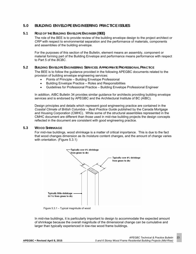
5.3 WOOD SHRINKAGE For mid-rise buildings, wood shrinkage is a matter of critical importance. This is due to the fact that wood changes dimension as its moisture content changes, and the amount of change varies with orientation. (Figure 5.3.1)
In mid-rise buildings, it is particularly important to design to accommodate the expected amount of shrinkage because the overall magnitude of the dimensional change can be cumulative and larger than typically experienced in low-rise wood frame buildings.
Figure 5.3.1 – Typical magnitude of wood

APEGBC Technical & Practice Bulletin APEGBC Revised April 8, 2015 5 and 6 Storey Wood Frame Residential Building Projects (Mid-Rise)
24
The moisture content eventually comes into equilibrium with the relative humidity of the air surrounding the wood. Wood supplied to construction sites is generally 15-19% moisture content, well below the fiber saturation point but still above the equilibrium moisture content of wood kept at the relative humidity of typical building indoor environments. The result of the above factors is that in wood framed construction an allowance must be made for an initial period of wood shrinkage, and then some cycling of dimension over the year as the indoor relative humidity changes. Average indoor RH is generally higher in summer than winter in heated buildings so the moisture content of the wood can cycle between about 15% and 5% (possibly higher in the exterior walls). As a result, wood in the building expands in the summer and shrinks in the winter. In platform-framed construction, the frame can shrink as much as 5% of the cumulative length of cross-grained wood in the structure. Where there are hygroscopically stable building elements (ones that don’t shrink) that are continuous across floors and/or independently supported to the ground, there can be significant vertical differential movement between the element and the wood frame envelope assemblies. This must be accommodated. Some examples include the following: a) The junction between wood frame and masonry walls must be flexible to accommodate initial
shrinkage and annual cycling movement while maintaining air and water tightness and fire separation characteristics. The BCBC does not allow combustible membranes to pass by firewalls. In most cases it is also not practical to rigidly attach the wood structure or interior finishes to masonry walls. Because of the above concerns, as well as concerns related to the relative flexibility of wood and masonry element in seismic situations, masonry firewalls are discouraged for mid-rise buildings. Proprietary systems are becoming available but the full range of issues around shrinkage and other matters need to be addressed in the specific design application under consideration as they are not inherently dealt with in the proprietary system itself.
b) If there are elements that do not shrink which penetrate the roof, the junction at the roof must be detailed to accommodate the expected differential movement. These could include elevator penthouses, the top of masonry firewalls, chimneys and plumbing stacks.
c) The use of masonry cladding independently supported to the ground must consider cumulative shrinkage. Masonry standards allow up to 11m to be supported to the ground without an intermediate shelf angle. Special consideration must be give to elements that span between the wood frame and the masonry cladding. This includes windows, vent terminations, and through wall flashings. In general shrinkage can be accommodated by making the opening in the brick extend below the elevation of projecting element and protecting the gap with a flashing. At upper floors cladding will generally need be supported by the frame and provided with movement joints dimensioned to accommodate the expected shrinkage.

APEGBC Technical & Practice Bulletin APEGBC Revised April 8, 2015 5 and 6 Storey Wood Frame Residential Building Projects (Mid-Rise)
25
d) If there are projections such as balconies that are attached to the frame but also provided
with supports or columns independently supported to the ground differential shrinkage can change the slope of the projections. Seasonal moisture variations occur such that shrinkage generally occurs indoors during the winter and outdoors during the summer. This must be accommodated in the design and detailing.
The cumulative amount of differential shrinkage can be reduced by being consistent in the amount of cross grained dimensional lumber in the load paths and by using dry wood. In platform framed construction much of the cross grained wood is in the floor structure. The floor platforms can be taken out of the load path by hanging the floor structure. For example, in the USA one balloon framing method used involves framing the wall panels with a single bottom plate and double top plate and hang the floor structure with joist hangers (Figure 5.3.2). This effectively takes the typical perimeter header or rim joist out of the equation when evaluating cumulative shrinkage – a substantial reduction in cross grain wood. It is necessary to be consistent across the floor plate, so that similar measures must be adopted for interior walls.
The use of structural members fabricated from engineered wood rather than dimensional lumber is also beneficial. Engineered wood products are manufactured with dry lumber so initial shrinkage is considerably less than sawn lumber. These products are also more dimensionally stable when subjected to changes in RH.
Figure 5.3.2 – Use of joist hanger to reduce amount of cross grain wood shrinkage.

APEGBC Technical & Practice Bulletin APEGBC Revised April 8, 2015 5 and 6 Storey Wood Frame Residential Building Projects (Mid-Rise)
26
5.4 CHANGE IN ENVIRONMENTAL LOADS – IMPACT ON BUILDING ENVELOPE An increase in building height from 4 storeys to 6 storeys generally increases the exposure of the building and thus increases the wind and rain load experienced by the assemblies that comprise the building envelope. The simplified procedures in the BCBC predict an increase in wind loads for a six storey building in the order of 10% over the loads predicted for a similar 4 storey building. This increased load factor needs to be considered by the design team along with other factors that influence exposure to determine the likely wind loading. Site characteristics like proximity to large open bodies of water, location on a hill, or open terrain can all have an impact at least as great as that associated with the increase from 4 to 6 storeys.
5.5 IMPACT OF INCREASED WIND AND RAIN LOADS The higher wind and rain loads needs to be assessed for the impact on the structure, attachment of cladding elements, and a variety of other issues that are commonly considered in the design and construction of high-rise buildings. Components of wood frame building envelopes that may be uniquely impacted by increased wind and rain loads include the following:
5.5.1 AIR BARRIER The air barrier system in building envelope assemblies must accommodate the imposed wind load and transfer it to the building structure. In many cases it is a combination of materials that comprise the air barrier system, however there are usually one or two materials that play a dominant role within any particular air barrier strategy. For example, sheet polyethylene and butyl sealant are the dominant materials in a sealed polyethylene approach to achieving air tightness. Breather type sheathing membranes (such as Tyvek Commercial Wrap) are the key material in an exterior air barrier strategy, while the exterior sheathing or interior GWB are the key materials in more rigid air barrier systems. All of these systems tend to perform acceptably (within the limitations of each system) when the wind load acts to cause the primary air barrier material to bear against the supporting structure. They are generally less able to accommodate the imposed wind load when the wind acts to pull air barrier materials away from the supporting structure. Air barrier systems that rely on breather type sheathing membrane products (such as Tyvek) on the outside of the sheathing may be particularly vulnerable to higher wind suction loads. There is potential for the wind to cause the membranes to tear around fasteners and other materials used to secure the cladding to the structure. Typically the practice in BC is that these exterior air barrier materials are supported at intervals by wood strapping and there is little evidence to suggest that tearing has been occurring in current wood frame construction. The use of cladding, such as masonry veneer, that relies on localized penetrations of the sheathing membrane by metal ties will increase the potential for tearing of air barrier materials. There is very little test data available to allow for a more analytical or even empirical approach to the determination of structural adequacy for these types of air barrier systems. Precautionary measures could include tightly spaced strapping to secure the membrane and selection of more robust (strength and tear resistance) membranes.

APEGBC Technical & Practice Bulletin APEGBC Revised April 8, 2015 5 and 6 Storey Wood Frame Residential Building Projects (Mid-Rise)
27
Figure 5.3.3 – Concentrated loads at metal ties Figure 5.3.4 – More evenly distributed loads using wood
strapping
5.5.2 SPECIFIED RATINGS FOR WINDOWS
Increased exposure conditions and thus higher loads dictate specification of higher performance levels for windows, both in terms of structural performance and water penetration resistance. In addition to the increase in wind loads, the DRWP calculation that is used to determine an appropriate water penetration performance class will also increase by approximately 10% when considering an increase in building height from 4 to 6 storeys. The result of the increase in loading is that some window assemblies that have been used in low rise wood frame buildings may not provide adequate performance in taller 6 storey buildings.
5.5.3 CUMULATIVE RUN-OFF Water that impacts on the walls and windows during wind driven rain events accumulates as in runs down the building to grade level. Features such as drip flashings encourage water to drip free of the building minimizing the impact of wetting on the components and materials below. However, it is likely that in many circumstances there will be more water accumulating on the lower levels of walls and windows in 6 storey buildings when compared with similar 4 storey buildings. This accumulation of run-off needs to be considered in designing the water shedding surface features of the building envelope. It may also be a factor in the selection of a more robust water penetration control strategy, and in the selection of more moisture tolerant materials (Figure 5.3.5).

APEGBC Technical & Practice Bulletin APEGBC Revised April 8, 2015 5 and 6 Storey Wood Frame Residential Building Projects (Mid-Rise)
28
Figure 5.3.5 – Cumulative effect of rainfall on an exterior wall
5.5.4 WIND UPLIFT ON ROOFS Higher wind loads result in higher wind uplift forces on the edges of roofs of 6 storey buildings. As a result, some roofing applications that are commonly used in low-rise buildings may not be appropriate for some sites (low slope asphalt shingle roofs, for example).
5.5.5 MOISTURE DURING CONSTRUCTION The detrimental effects of moisture during construction (such as deterioration of wood products, needing dry substrates for installation of water-proofing materials) are accentuated in six storey buildings. This is caused by both the greater height of exposure as well as the greater potential duration of exposure to wetting. More complete and robust weather protection may be required during construction on 6 storey wood frame buildings.
5.6 INCREASED STRUCTURAL MASS The additional vertical loads imposed by increasing the building height to 5 or 6 storeys will require that the wood framing provide additional capacity. Additional framing may also be required to transfer lateral loads within the taller structure. Such increased framing requirements may involve massive timber framing members, closer spacing of framing members, use of more engineered wood products or a combination of these approaches. From a building envelope perspective a change in framing that results in more structure can limit the space available to place insulation within the framed portion of the wall assembly. For example, increasing the studs from 38x140@400 to 102x140@400 studs with R21 batt insulation will result in a decrease in effective R-Value from R18.3 to R14.8 overall. Designers need to be aware of this potential change to the ratio of insulation and framing and find ways to accommodate it in achieving the overall energy targets and/ or code requirements for the building. Strategies such as lower percentage of glazed area, use of additional insulation layers,

APEGBC Technical & Practice Bulletin APEGBC Revised April 8, 2015 5 and 6 Storey Wood Frame Residential Building Projects (Mid-Rise)
29
or modified HVAC systems can be used to accommodate a decrease in insulation level within the stud space. The increased framing on the lower levels of six storey wood frame buildings will also limit the space available for service penetrations such as ducts, and piping. More careful planning and coordination of the structural, mechanical and building envelope system interaction will be required during the design phase of projects.
5.7 MAINTENANCE AND RENEWAL All buildings will require maintenance and renewals activities to be undertaken over their lifespan. Decisions made during the design stage of a project will impact on the ease and cost of future maintenance and renewal activities.
5.7.1 ACCESS Mid-rise buildings are tall enough that ladder access is generally not possible. It becomes necessary to consider access methods that are more common for high-rise buildings such as suspended access equipment (swingstages and bosun chairs). Alternately boom lifts can be used to access upper areas of these 6 storey buildings. If suspended access equipment is intended then an appropriate roof anchoring system must be installed and the logistics of moving swingstages around the building perimeter must be worked out. Highly articulated building features (such as roof overhangs, balconies and steps in building section) can make this type of access difficult.
Figure 5.3.6 - Highly articulated roof line makes provision of roof anchors and use of suspended access equipment difficult. If boom lifts are to be relied on, access provisions must be planned at the design stage. Parking garage roof slabs must accommodate the vehicle loads, and hard and soft landscape features must allow for movement of the portable lift equipment around the perimeter of the building.

APEGBC Technical & Practice Bulletin APEGBC Revised April 8, 2015 5 and 6 Storey Wood Frame Residential Building Projects (Mid-Rise)
30
5.7.2 ENVELOPE DESIGN Generally, maintenance and renewals is more expensive for taller buildings due to the higher costs of access. However, for mid-rise buildings there are some decisions that can be made during design to ease the maintenance burden. Some of these include the following:
5.7.2.1 Dryer Vents
Dryer vents require periodic cleaning due to lint build-up. The implications of not cleaning dryer vents can be significant, not only in terms of dryer operation, but in terms of envelope performance. The back pressure caused by plugged dryer vents can result in warm moist air being forced into the exterior wall assembly. Locating vents where they are readily accessible (on balconies) will facilitate regular cleaning. However, these exhaust locations can create problems associated with the condensation of exhaust air on colder components of the building envelope if not discharged to a space where the air is very quickly mixed with outdoor air.
Alternate solutions could include the use of common ducts to the roof with booster fans, or the use of a secondary lint screen clean-out location close to the dryer (within the laundry room typically). This latter solution greatly reduces (but does not eliminate) the need for cleaning of the exterior exhaust hood screen.
5.7.2.2 Interior Glazed Windows
Replacement of insulating glass units is typically required every 10 to 25 years over the life of a building. While this work can be done from the exterior, the access set-up costs to replace one piece of glazing from the exterior can be very high. Therefore, the use of windows that are glazed from the interior is generally preferable
5.7.2.3 Durable Finishes and Sealants Sealants and finishes are the items requiring most frequent maintenance and renewal activity for the building envelope. Therefore, utilizing more durable materials can cut down on overall costs considerably. Higher quality paints and silicone sealants are usually only marginally more expensive than the minimum acceptable solution but can add a lot of value over the life of the building.
Figure 5.3.7 - Planning for access to building perimeter is essential if boom lifts are to be used. Capacity of parking garage roof slab and hard and soft landscaping features are critical considerations.

APEGBC Technical & Practice Bulletin APEGBC Revised April 8, 2015 5 and 6 Storey Wood Frame Residential Building Projects (Mid-Rise)
31
6.0 QUALITY ASSURANCE/QUALITY CONTROL The SER, Fire Protection Engineer and Building Envelope Engineer must apply quality assurance processes when providing professional engineering services on mid-rise buildings which as a minimum meet the requirements of APEGBC Quality Management Bylaws 14(b), (1), (2) and (4) with regards to:
(1) Retention of complete design and review files for their projects for a minimum period of 10 years;
(2) In-house checks of their designs as a standard procedure; (4) Field reviews, by members or licensees, of their projects during construction.
In addition, Bylaw 14(b) (3) requires that all structural designs for mid-rise buildings must be independently reviewed. Bylaw 14(b)(3) reads as follows:
“concept reviews of their structural designs by members or licensees not originally involved in the designs;
Concept reviews under (3) above shall be in addition to any checks which are undertaken under (2) above. These reviews shall evaluate the structural designs to determine if the structural concepts appear complete, consistent and general compliance with the appropriate codes. Representative samples of the individual elements shall be checked to evaluate the analysis, design and detailing procedures used by the design engineer.”
The APEGBC Guideline for Professional Structural Concept Review is to be followed when carrying out such reviews. The checklist for Professional Structural Concept Review form which is attached to the Guideline for Professional Structural Concept Review is to be completed and sealed with signature and date by the professional engineer completing the concept review. With respect to the Structural Engineer’s Field Review program following are some recommended procedures to be followed: a) See Section 3.3 (c) of this bulletin regarding the provision of notes on structural drawings
relevant to the structural engineer’s Field Review process.
b) Field Reviews are to occur on a floor by floor basis. Additional Field Reviews should take place after all services have been installed and prior to any boarding. Re-review of required corrective measures may be facilitated by appropriate photo documentation.
c) It is recommended that there be a start up meeting to clarify all the review requirements prior to the commencement of framing.
With respect to independent peer review considerations for Fire Protection Engineers it is recommended that when alternative solutions are proposed under Clause 1.2.1.1.1 b) of the BCBC or when unique conditions occur that may affect the performance of life safety or fire protection systems on mid-rise buildings the Fire Protection Engineer should propose to the architect and CRP that the design be independently reviewed by another Fire Protection Engineer. Such independent reviews should be conducted in accordance with the Society for Fire Protection Guide for Peer Review which confirms that as part of the peer review process the preparation of a report is required to document the process and findings. Finally with respect to Field Reviews the bylaw implies that all Field Reviews are to be undertaken by Members. There are some circumstances where an assisting non-Member or a subordinate Member may be delegated to carry out Field Reviews under the direct supervision and full responsibility of the EOR. Direct supervision of a task such as Field Reviews which occurs outside the office is, by definition, difficult and care must be taken to ensure that Field Reviews carried out in this context

APEGBC Technical & Practice Bulletin APEGBC Revised April 8, 2015 5 and 6 Storey Wood Frame Residential Building Projects (Mid-Rise)
32
meet the standard expected of a professional engineer. Direct supervision of those carrying out Field Reviews would typically take the form of providing specific instructions on what to observe, check, confirm, test, record and report back to the professional engineer. Where circumstances go beyond this or where engineering decisions/judgments are required, contact must be made with the EOR so that the engineering decisions/judgments are made by the EOR and, further direction/instruction can, at that point, be provided to the non-Member or a subordinate Member operating under the direct supervision and responsibility of the EOR. When an EOR is directing a non-Member or a subordinate Member with respect to undertaking Field Review tasks that are to be carried out under the EOR’s direct supervision, the EOR must ensure that such work is carried out in a fashion which meets the definition of “direct supervision.” Section 1(1) of the Engineers and Geoscientists Act states:
“Direct supervision” means the responsibility for the control and conduct of the engineering of geosciences work of a subordinate.”
Meeting the intent of this definition includes having the EOR exercise his or her professional judgment and due diligence in addressing the following matters: 1. Considering all the circumstances surrounding the project and the above context, whether or
not it is appropriate to delegate one or more of the Field Reviews to a non-Member or a subordinate Member.
2. Consideration of the level, complexity or critical nature of the Field Review to be conducted, in order that the EOR can be satisfied with the quality and accuracy of the observations being made by the assisting non-Member or a subordinate Member.
3. Whether or not the assisting non-Member or a subordinate Member that will be carrying out the Field Reviews, has the appropriate level of training and experience, taking into consideration the complexity of the project at hand.
4. The instruction required to be provided to the assisting non-Member or a subordinate Member on the level of effort to be exercised in the Field Review, the level of detail required when reporting on the Field Review and the specific aspects of the construction activities, which are to be included in the Field Review.
5. Subsequent review of the field reports by the EOR and follow up, as required.

APEGBC Technical & Practice Bulletin APEGBC Revised April 8, 2015 5 and 6 Storey Wood Frame Residential Building Projects (Mid-Rise)
33
7.0 EDUCATION, TRAINING AND EXPERIENCE All professional engineers must adhere to APEGBC Code of Ethics Principle 2 (to undertake and accept responsibility for professional assignments only when qualified by training or experience), and therefore must evaluate his/her qualifications and possess appropriate education, training and experience consistent with the professional engineering services being provided. APEGBC require that all Members providing professional engineering services for structural, fire protection and building envelope services relevant on mid-rise building projects have the appropriate expertise and experience to understand and apply the concepts presented in this bulletin. The sections of this bulletin on Structural Engineering Practice Issues (3.0), Fire Protection Engineering Practice Issues (4.0) and Building Envelope Engineering Practice Issues (5.0) all reference relevant standards and practices which Members providing these types of services must be experienced in applying. Members should not proceed with providing professional services for mid-rise buildings in these fields of practice unless they are familiar with and experienced in dealing with and applying the concepts presented in this bulletin.

APEGBC Technical & Practice Bulletin APEGBC Revised April 8, 2015 5 and 6 Storey Wood Frame Residential Building Projects (Mid-Rise)
34
8.0 REFERENCE AND RELATED DOCUMENTS Wood Design Manual 2005. Canadian Wood Council. Ottawa, Ontario. Introduction to Wood Design - A Learning Guide to Complement the Wood Design Manual 2005. Canadian Wood Council. Ottawa, Ontario.
Note: This reference can be used for shrinkage related calculations in 2009 APEGBC Guidelines.
CSA O86 - Engineering Design in Wood. 2009. Canadian Standards Association. Toronto, Ontario. To be published. Marsh, W. A. Updated Seismic Design of Wood Frame Buildings. Document prepared for the Executive Committee of the Structural Engineering Consultants of BC. 1997
Note: This is the first design example on wood-frame construction by Structural Engineering Consultants of BC. The footprint of this building was used in the 6-storey design example for which sample calculations were prepared as contained in Appendix E of the APEGBC Technical and Practice Bulletin - Structural, Fire Protection and Building Envelope Professional Engineering Services for 5 and 6 Storey Wood Frame Residential Building Projects (Mid-Rise Buildings).
Marsh, W. A. Multi-Unit Residential Building Design According to Part 4 Seismic Provisions of NBCC 2005. Document prepared for the NBCC 2005 Seismic Design Seminar, Vancouver Structural Engineers Group Society. 2006
Note: This is the second design example on wood-frame construction by Vancouver Structural Engineers Group Society. The footprint of the same building was also used in the 6-storey design example for which sample calculations were prepared as contained in Appendix E of the APEGBC Technical and Practice Bulletin - Structural, Fire Protection and Building Envelope Professional Engineering Services for 5 and 6 Storey Wood Frame Residential Building Projects (Mid-Rise Buildings).
National Building Code of Canada 2005. Canadian Commission on Building and Fire Codes, National Research Council of Canada. Ottawa, Ontario. Ni, C., Popovski, M. Seismic Performance of 6-Storey Wood Frame Buildings. Report prepared for Building and Safety Policy Branch, Ministry of Housing and Social Development, Government of BC. Victoria, British Columbia. February 2009 Rainer, J.H.; Karacabeyli, E.. Ensuring Good Seismic Performance with Platform Frame Wood Housing. Construction Technology Update No. 45. National Research Council. 20004 p. <http://irc.nrc-cnrc.gc.ca/pubs/ctus/45_e.html>
Note: This NRC Construction Update summarizes the recommendations based on the observations (please see publication below) on seismic resistance for wood-frame construction. The publication identifies weak first storey as an issue for certain buildings.
Rainer, J.H.; Karacabeyli, E. Performance of Wood-Frame Building Construction in Earthquakes. Special Publication No. SP-40. 28 p. FPInnovations Forintek. 1999
Note: This publication gives a summary of findings from reconnaissance studies on performance of wood-frame buildings in 7 earthquakes. The publication identifies weak first storey as an issue for certain buildings.

APEGBC Technical & Practice Bulletin APEGBC Revised April 8, 2015 5 and 6 Storey Wood Frame Residential Building Projects (Mid-Rise)
35
SEAOC, 2007. 2006 IBC Structural/Seismic Design Manual, Volume 2. Building Design Examples for Light-Frame, Tilt-Up and Masonry. Structural Engineers Association of California. Sacramento, California
Note: While this publication provides good design examples, the current BCBC must be followed when applying the concepts presented.
BC Building Code (2006). Published by the Office of Housing and Construction Standards, BC Ministry of Forests and Range and Minister Responsible for Housing. Victoria, British Columbia. Guidelines for Structural Engineering Services for Building Projects. APEGBC. Burnaby, British Columbia. 1993 Coastal Climate of British Columbia – Best Practice Guide. Canada Mortgage and Housing Corporation (CMHC)

APEGBC Technical & Practice Bulletin APEGBC Revised April 8, 2015 5 and 6 Storey Wood Frame Residential Building Projects (Mid-Rise)
36
APPENDIX A: MINISTERIAL ORDER

APEGBC Technical & Practice Bulletin APEGBC Revised April 8, 2015 5 and 6 Storey Wood Frame Residential Building Projects (Mid-Rise)
37

APEGBC Technical & Practice Bulletin APEGBC Revised April 8, 2015 5 and 6 Storey Wood Frame Residential Building Projects (Mid-Rise)
38

APEGBC Technical & Practice Bulletin APEGBC Revised April 8, 2015 5 and 6 Storey Wood Frame Residential Building Projects (Mid-Rise)
39

APEGBC Technical & Practice Bulletin APEGBC Revised April 8, 2015 5 and 6 Storey Wood Frame Residential Building Projects (Mid-Rise)
40

APEGBC Technical & Practice Bulletin APEGBC Revised April 8, 2015 5 and 6 Storey Wood Frame Residential Building Projects (Mid-Rise)
41
APPENDIX B: DEFINITIONS Authority Having Jurisdiction (AHJ) The governmental body responsible for the enforcement of any part of the BCBC or the official or agency designated by that body to exercise such a function. British Columbia Building Code (BCBC) 2006 The British Columbia Building Code (BCBC) used in British Columbia for the construction or alteration of buildings. Coordinating Registered Professional (CRP) Often referred to as the "Prime Consultant", the CRP is the individual who is registered as a Member in good standing of the APEGBC or the AIBC, and who has the responsibility to coordinate the design and Field Review of the various design professionals (such as electrical, structural, mechanical, fire protection, geotechnical, architectural) for the project. Electrical Engineer of Record (EER) The Member with general responsibility for electrical integrity of the electrical systems as provided for in the APEGBC Guidelines for Electrical Engineering Services for Building Projects. Engineer of Record (EOR) The Member taking overall professional responsibility related to the carrying out of a particular professional activity. Field Review A review of the work: (a) at a project site of a development to which a building permit relates, and (b) where applicable, at fabrication locations where building components are fabricated for use at the project site that a registered professional in his or her professional discretion considers necessary to ascertain whether the work substantially complies in all material respects with the plans and supporting documents prepared by the registered professional for which the building permit is issued. Fire Protection Engineer of Record (FPER) The Member, registered by the APEGBC as a Professional Engineer, who specializes in the science of Fire Protection Engineering with the responsibility for completing any aspect of the Fire Protection Engineering as outlined in Appendix D of this bulletin. In general, the FPER will be responsible for specific parts of the Schedules B-1, B-2, and C-B of the BCBC as well as the design of fire and life safety systems. Another Member, such as the MER may provide a performance based specification at the incipient stages of a project. This Member is not the FPER for the purposes of this bulletin. Fire Protection Engineering The application of science and engineering principles to protect people and their environment from destructive fire and includes:
analysis of fire hazards; mitigation of fire damage by proper design, construction, arrangement, and use of buildings,
materials, structures, industrial processes, and transportation systems; and the design, installation and maintenance of fire detection and suppression and communication
systems. Fire Protection Engineer (FPE) A Member, registered by APEGBC as a Professional Engineer, who specializes in the science of Fire Protection Engineering with the responsibility for completing any aspect of the services described in Appendix D: Guidelines for Professional Practice for a Fire Protection Engineer. Fire Resistance Rating (FRR) The time in minutes or hours that a material or assembly of materials will withstand the passage of flame and the transmission of heat when exposed to fire under specified conditions of test and performance

APEGBC Technical & Practice Bulletin APEGBC Revised April 8, 2015 5 and 6 Storey Wood Frame Residential Building Projects (Mid-Rise)
42
criteria, or as determined by extension or interpretation of information derived there from as prescribed in the BCBC. Since it is not practicable to measure the fire resistance of constructions in situ, they must be evaluated under some agreed test conditions. A specified fire-resistance rating is not necessarily the actual time that the assembly would endure in situ in a building fire, but is that which the particular construction must meet under the specified methods of test. Firestopping (obtained from NRC) A material, component or system, and its means of support, used to fill gaps between fire separations, between fire separations and other construction assemblies, or used around items which wholly or partially penetrate fire separations, to restrict the spread of fire and often smoke thus maintaining the integrity of a fire separation. Fireblocking (obtained from NRC) A material, component or system installed in a concealed space in a building to restrict the spread of fire and often smoke in that concealed space, or from that concealed space to an adjacent space. GWB Gypsum Wallboard. Letters of Assurance Standard forms of the BCBC informing the AHJ which aspects of a project design and Field Reviews are the responsibility of a particular registered professional. Mechanical Engineer of Record (MER) The Member with general responsibility for the mechanical integrity of the mechanical systems as provided for in the APEGBC Guidelines for Mechanical Engineering Services for Building Projects. Member A Member or the holder of a Limited Licence acting within their scope of practice in good standing of the APEGBC in accordance with the Engineers and Geoscientists Act. Struct. Eng. (Struct.Eng.) A grade of membership granted by APEGBC to a Structural Engineer who has been qualified and approved to take responsibility for structural engineering services as the SER for buildings in British Columbia that fall under Parts 4 of the BCBC, the City of Vancouver Building Bylaw or another local building code or bylaw of the AHJ. Structural Engineer of Record (SER) The Member with general responsibility for the structural integrity of the primary structural system as provided for in the APEGBC Guidelines for Structural Engineering Services for Building Projects. Tc The period given by the BCBC for shearwall or other structures in Clause 4.1.8.11.3(c) of the BCBC. Formula being; Tc = 0.05(hn)^0.75, where hn is m.

APEGBC Technical & Practice Bulletin APEGBC Revised April 8, 2015 5 and 6 Storey Wood Frame Residential Building Projects (Mid-Rise)
43
APPENDIX C: E XAMPLE TOLERANCES ON STRUCTURAL DRAWINGS AND WOOD FRAME SHEARWALLS A. Tolerances on Structural Drawings
Following are example construction tolerances than can be referenced on the structural drawings; a. Wall Construction Tolerances
1. Wall Stud Spacing +/- 6 mm 2. Wall Plumb +/- 12 mm/2440 mm 3. Wall Level +/- 6 mm/914 mm 4. Wall Square +/- 9 mm/2440 mm 5. Variation in Stud Lengths +/- 3 mm 6. Individual Stud out of Plane +/- 3 mm 7. Straightness of Top and Bottom Pates +/- 6 mm/914 mm 8. Lap of Top Plates acting as Chord Transfers +/- 12 mm 9. Specified Nail Spacing +/- 6 mm 10. Maximum Nail Penetration into Sheathing 3 mm 11. Maximum Spacing between Sheathing and Supports 3 mm
b. Floor and Roof Construction Tolerances
1. Joist Spacing +/- 6 mm 2. Overall Floor Level +/- 12 mm/3050 mm 3. Localized Floor Level +/- 6 mm / 914 mm 4. Joist Depth Variation +/- 3 mm 5. Specified Nail spacing +/- 6 mm 6. Maximum Nail Penetration into Sheathing 3 mm 7. Truss Spacing +/- 6 mm 8. Truss Plumb +/- 6 mm / 1220 mm 9. Truss Bearing Requirements +/- 6 mm2 10. Chord and Web Bracing – as per individual truss design requirements 11. Truss Construction Tolerances – as per TPIC 12. Beam Spacing +/- 6 mm 13. Nail Spacing for Built-Up Beams +/- 3 mm 14. Variation in Individual Beam Depth of Build-Up Beam +/- 3 mm 15. Beam Bearing Requirements +/- 3 mm 16. Beam Level +/- 12 mm / 2440
mm 17. Beam Plumb +/- 3 mm
B. Behaviour of Wood Frame Shearwalls
a) Nailed wood panel shearwalls, in common with other shear yielding Seismic Force Resisting Systems such as braced frames and moment frames, have the potential to exhibit soft story behavior when subject to design level earthquake ground motions.
b) Prior to the changes made to the BCBC on April 3, 2009 (Ministerial Order M121) the BCBC provided two methods of determining seismic design forces for buildings, the Equivalent Static Force Procedure and the Dynamic Analysis Method. There are restrictions on the use of the Equivalent Static Force Procedure, but if irregularity Types 5 and 6 are not permitted, mid-rise wood buildings will generally be considered to be regular buildings and be permitted to use the Equivalent Static Force Procedure. Seismic design force levels are a function of the building’s fundamental period of vibration and decrease as the period increases. The BCBC provides an empirically derived period, called the code period, Tc, that can be used to calculate the lateral force for design, but it also allows for a period to be calculated using engineering mechanics principles taking into consideration the buildings stiffness and mass. The period calculated by this method can be used to calculate the lateral design forces using the Equivalent Static Force Procedure, but BCBC places an upper limit on the period used for

APEGBC Technical & Practice Bulletin APEGBC Revised April 8, 2015 5 and 6 Storey Wood Frame Residential Building Projects (Mid-Rise)
44
design of twice the code period Tc, to insure the design forces are not too small. Thus the period used for design of the seismic forces by the Equivalent Static Force Procedure, termed Ta, will be bounded, Tc<Ta<2Tc. Current practice generally has been to use the code period Tc as this does not require any period calculation, but the calculated period is often much larger and so the design forces can generally be reduced. The Dynamic Analysis Method can be used to determine the seismic forces but they cannot be less than 80% of the seismic forces determined using the Equivalent Static Force Procedure provided the building is considered regular. If the building is not regular the dynamically calculated forces cannot be less than 100% of the Equivalent Static Force Procedure forces.
c) The APEGBC Six Storey Wood Frame Building Structural Task Force (the “Task Force”) undertook a study to examine whether soft storeys would be an issue for mid-rise wood structures designed to the BCBC seismic design provisions. The methodology of the study was to subject a wood shearwall system, designed to BCBC using different force levels as described in b. to a series of non-linear time history analyses using ten earthquake records scaled to represent the expected hazard.
d) If the building is designed by the Equivalent Static Force Procedure using Rd=3.0 and the empirical code period (Static at Tc), as has traditionally been done for wood-frame buildings, it is expected that there will be sufficient strength to inhibit soft story formation. Consequently, the Task Force recommended that this option is retained in the Bulletin and is equally applicable to wood frame buildings of 4 storeys or less.
e) FPInnovations Forintek also undertook a study of this issue using a representative building. Dynamic analyses were performed by Forintek and Colorado State University using earthquake records provided by UBC. The building design strength used for this study was based on Rd=3.0 and a design Ta of twice the code formula Tc. The design selection provided 20% additional capacity. While the building was likely representative of an average design, it was not a lower bound strength case. The study showed that for the building examined, soft storeys would not be an issue.
f) To investigate the potential for soft storeys the Task Force used the lowest level of design that would be allowed by the BCBC. This was determined using the Dynamic Analysis Method and scaled to 80% of the force determined using the Equivalent Static Force Procedure with 2 x Tc. The results of many nonlinear analyses on these models, using the ten earthquake records scaled to represent the design hazard, showed that soft storeys developed for about half the records. This number of failures indicated that for the mid-rise buildings the design force levels should be increased above the minimum force that could be calculated using the BCBC.
g) A number of possible solutions to the soft storey issue will be considered for the NBC 2015. In the interim two simple solutions would be to prohibit certain force determination procedures and/or to specify an increase in the minimum force level. In consultation with some members of CANCEE, wood industry engineers and wood design consultants, it was decided that the simplest method would be specify an increase in the minimum force level. Analyses showed that an increase of 50% in the design force above the minimum resulted in very few failures. This can be achieved by not allowing the reduction to 80% of the force determined using Equivalent Static Force Procedure and by then increasing the minimum Equivalent Static Force Procedure results by another 20%. This would not require any change in the current practice which uses Tc to determine the design forces, unless Ta is close to Tc, which has not been observed in the analyses carried out in this study.

APEGBC Technical & Practice Bulletin APEGBC Revised April 8, 2015 5 and 6 Storey Wood Frame Residential Building Projects (Mid-Rise)
45
APPENDIX D: GUIDELINES FOR PROFESSIONAL PRACTICE FOR A FIRE PROTECTION ENGINEER The following document represents Section 4 the APEGBC Guideline for Fire Protection Engineering Services for Building Projects which has not been finalized for publication. This document provides appropriate guidance on professional practice for APEGBC Members acting as the Fire Protection Engineer on a mid-rise building project. 4.0 GUIDELINES FOR PROFESSIONAL PRACTICE
The services which a FPE should consider as part of good practice are outlined below. This outline may assist in explaining the services of the FPE to a client; but is not exhaustive. There are three broad ranges of services provided by FPE’s in building projects. These are Design Services (FPER) and two types of code services, the Fire and Life Safety Fire Protection Engineering Services and Prescriptive Design Services provided by the FPE. An FPE may provide one or more types of services on the same project. The Design Services may also be performed by an MER or EER and the information contained herein should in no way be construed as restricting their ability to perform such designs provided they are qualified to do so. Often, the MER may provide performance based specifications and sign Letters of Assurance. The FPE who provides the detailed design for the fire suppression system is the FPER for the purposes of this guideline.
4.1 Scope of Services – Design
Fire Protection Design Services may be provided by an FPE, the FPER, the EER (e.g. for the Fire Alarm System), the MER (e.g. for the Sprinkler System, Standpipe System, Kitchen Suppression System, dry chemical suppression systems, or gaseous agent suppression systems), or a combination of the design professionals of record and Specialist Engineers. Where the MER or EER are performing the designs, they should also refer to the appropriate Guidelines, e.g. the Guidelines for Mechanical Engineering Services for Building Projects or Guidelines for Electrical Engineering Services for Building Projects. For existing buildings, the FPE may act as the CRP and be responsible for providing or coordinating most, if not all, design services on the project. Before commencement of Design Services, the FPE should discuss with the client:
4.1.1. The terms of reference and the scope of work for basic services and additional services; 4.1.2. Reach agreement on fees, payment schedule and professional liability insurance coverage; 4.1.3. Reach agreement on a contract. (Documents No. 31 or 32 prepared by the Association of
Canadian Engineering Companies are recommended as a basis for this contract.); 4.1.4. For a "fast-track" project, in addition to the above, the FPE should establish with the client the
terms and conditions under which preliminary or partially complete contract documents may be issued in advance and clearly define the requirements for partially complete contract documents;
4.2 Basic Fire Protection Engineering Services
The usual stages of the basic services, as discussed below, are generally organized in an agreement according to the sequential stages of a typical project. Each stage of the basic services generally contains those items which pertain most typically to the progress of work for that construction stage. Because of the requirements of a specific project, certain basic services/activities may be required to be performed out of the normal sequence or in different stages than indicated in the scope of services.

APEGBC Technical & Practice Bulletin APEGBC Revised April 8, 2015 5 and 6 Storey Wood Frame Residential Building Projects (Mid-Rise)
46
In many projects, the FPER is brought on as part of a design build contract. Many of the following steps therefore would not be required. Even for a designer active in earlier stages of the project, involvement in many of these steps may be minimal or not relevant. For instance, reports on types of systems will generally not be required. In addition, the FPER may be responsible for only one of the disciplines potentially within the field of Fire Protection Engineering. Other engineers, such as the MER, the EER, or other FPEs, may be undertaking design for the other fields within the scope of fire protection design. Similarly, many aspects of the following, including most of Sections 4.2.3 and 4.2.4, would not be applicable to an FPE engaging in Fire and Life Safety Analysis. While some aspects of other sections are relevant, research results may lead to only a few or possible one practical design alternative.
4.2.1 "Conceptual" or “Schematic" Design Stage
In the Conceptual or Schematic Stage, the FPER may:
4.2.1.1. Attend, as required, periodic meetings with the client and design team to obtain the client's instructions regarding the client's functional, aesthetic, cost and scheduling requirements to prepare a preliminary design concept and to report on the fire protection systems which may include consideration of economy, performance, capital cost, sustainability, compatibility with other design elements and requirements of relevant codes and authorities;
4.2.1.2. Assist the CRP or owner in:
(a) defining the need for any specialty consulting services which may be required for the project, e.g., Alternative Solutions, code, and Certified Professional, life cycle assessment;
(b) reviewing the project schedule including any milestone dates; (c) determining channels of communication; (d) determining drawing standards and Specifications format; (e) determining the number and timing of project team meetings during each stage of the
project;
4.2.1.3. Establish dates by which information affecting the fire protection design will be needed from other disciplines;
4.2.1.4. Conduct a site review and review existing drawings where appropriate; 4.2.1.5. Establish criteria for the electrical, mechanical and other consultants as required; 4.2.1.6. Identify fire protection design criteria, prepare preliminary calculations for:
(a) sprinkler and standpipe design, establish basic hydraulic design criteria, water supply
arrangements and characteristics, need for fire pump or unusual water supply, type of standpipe system,
(b) fire alarm design, basic fire alarm system requirements, special fire alarm system
requirements such as high building measures and institutional needs, (c) other fire protection system designs, basic system criteria required to provide the basis for
the system design.

APEGBC Technical & Practice Bulletin APEGBC Revised April 8, 2015 5 and 6 Storey Wood Frame Residential Building Projects (Mid-Rise)
47
4.2.1.7. Consider developing with the client and CRP and the design team sustainability goals for the project.
4.2.1.8. Develop the fire protection scheme for the fire protection systems. Develop alternate schemes
where appropriate. Consider materials and systems suitable to the project requirements. Consider the requirements of the other design professionals and provide the information they require;
4.2.1.9. Check applicable codes, regulations and restrictions, insurance requirements and other factors
affecting the design of the project; 4.2.1.10 Prepare a preliminary cost estimate or cooperate appropriately with others responsible for
reporting the estimate; 4.2.1.11. Determine the allocation of suitable space for service rooms and other major fire protection
installations; 4.2.1.12. Establish, where appropriate, comparative information to be used in selection of fire protection
systems for the project; 4.2.1.13. Provide, if required, brief outline specifications for proposed materials; 4.2.1.14. Describe the major fire protection system(s) and each significant component and material; 4.2.1.15. Explain to the client all new construction materials or new techniques proposed for use in the
project and their alternatives, including the risks, advantages and disadvantages over both the short and long term, so that the client can weigh the choices and make an informed decision before the FPE proceeds further;
4.2.1.16. Advise the client of the recommended fire protection systems. Review the effect of these
systems on the fire protection construction budget for the project; 4.2.1.17. A client may assume responsibility for all or some of the foregoing Conceptual or Schematic
Design Stage activities provided: (a) the FPE's ability to satisfy the requirements of the subsequent stages of these Guidelines is
unimpaired; (b) the responsibility for such preliminary design activities is clearly defined in writing; (c) the client or FPE, in writing, waives the FPE's responsibility for such preliminary design
activities and their effect on the selection of the fire protection systems. This waiver does not relieve the requirement for the FPER to comply with items included as signatory parts of the Schedules B-1 and B-2.
4.2.2 Design Development Stage
In the Design Development Stage when the selected scheme is developed in sufficient detail to enable commencement of the final design and construction documents by all participants of the design team, the FPER may:
4.2.2.1. Attend, if required, meetings with the client and design team; 4.2.2.2. Consider re-visiting the sustainable goals and strategies identified during the conceptual design
stage of the project. 4.2.2.3. Review results of studies by appropriate specialist consultants;

APEGBC Technical & Practice Bulletin APEGBC Revised April 8, 2015 5 and 6 Storey Wood Frame Residential Building Projects (Mid-Rise)
48
4.2.2.4. Prepare preliminary fire protection analysis and design calculations for typical fire protection
elements of the fire protection systems. Select appropriate equipment; 4.2.2.5. Prepare preliminary design drawings based on information coordinated with other consultants
showing layouts of typical areas; 4.2.2.6. Prepare or edit the "Outline Specifications" for fire protection items, as required; 4.2.2.7. Coordinate fire protection design with space and servicing criteria to meet the requirements of
the other design team participants. In particular, notify the EER, MER, and/or the Architect of all points of interface between the fire protection and the other disciplines and determine as soon as possible the electrical characteristics and electrical requirements of all fire protection loads and potential conflicts between the fire protection, mechanical, and electrical riser locations;
4.2.2.8. Coordinate the location of the fire hose and standpipe systems with other disciplines of the
project team to ensure that the standpipe risers are properly protected without compromising the minimum clearance in the exiting stairs.
4.2.2.9. The FPER is responsible for specifying the types of fire suppression systems used in areas
subject to freezing and the development of appropriate design details or specifications. If heat tracing is provided, the MER is responsible for specifying the minimum heating per unit area or per unit length of pipe, and the type and thickness of thermal insulation. Where there is no MER, then the FPER takes over the role.
4.2.2.10. Submit design development documentation for review and approval by the client. 4.2.3 Contract Document Stage 4.2.3.1 General:
(a) design the fire protection systems; (b) attend periodic coordination meetings, as required; (c) coordinate with the AHJ as required; (d) establish testing and Field Review requirements; (e) comply with fire resistance requirements as determined by the CRP or specialty
consultants. (f) confirm that the fire protection systems meet the sustainable goals of the project and that
the sustainable goals identified by the design team at the Design Development Stage are met with respect to the responsibilities of the FPER.
(g) seal documents per the Engineers and Geoscientists Act. (h) all designs must receive an in-house design check as a standard procedure as per Bylaw
14 (b) (2) of the Act.
4.2.3.2. Fire Protection Calculations The FPER must prepare fire protection calculations to support all fire protection designs. The fire protection calculations should be prepared legibly and presentably and filed by the FPER for record purposes. Hard copy of input and output of any computer analysis should be included as well as a description of the software used.

APEGBC Technical & Practice Bulletin APEGBC Revised April 8, 2015 5 and 6 Storey Wood Frame Residential Building Projects (Mid-Rise)
49
In general, fire protection calculations include but are not limited to: (a) design criteria:
discussion and description of design basis including assumptions; codes and design standards used with edition dates; list of fire protection design parameters and provisions greater than code requirements
as requested by the client or otherwise used by the FPER; (b) location diagrams for fire protection elements; (c) computer analysis and design results, if applicable; (d) special studies and analysis where required by code;
4.2.3.3. Fire Protection Design The fire protection designs are usually based on codes and referenced standards (such as
those prepared by NFPA and ULC) Other design guides, such as ASHRAE, the electrical code, and indirectly referenced NFPA standards, should be used where appropriate. In addition, there may be designs based on criteria determined by other FPE’s.
4.2.3.4. Fire Protection Drawings Prepare complete, contract drawings. The drawings should be made, where possible, to the
same scale as that of the building layout drawings and should define the work: Where scale of drawings or complexity of work make drawing difficult to be read and
interpreted, separate drawings should be provided for such areas of the work as fire protection and other special systems;
(b) schematics and diagrams should be provided as required for all major systems with notes
to describe the function of control, flow and operation; (c) plot plans and/or site plans showing water supply arrangements and connections to public
utility services as required, complete with elevations, should be included; (d) for hydraulic calculations, node points with self explanatory interconnection between the
drawings and hydraulic calculations; (e) floor plan layouts for all design systems such as sprinkler or fire alarm systems as
appropriate should be provided. Complete pipe and/or conductor sizing should be shown on these documents. Seismic restraint details should be provided. Sizes, types, locations and temperature ratings of all sprinkler heads and hose connection outlets pressure regulating pressures and location of valves and types of fire alarm devices should be shown;
(f) to avoid conflicts, supplementary details should be provided for valve/pump or electrical
rooms and congested areas;
(g) where the FPER is also responsible for wiring, locations should be indicated where protection of conductors is mandated by code (such as required for high buildings or fire pumps). Wiring locations are often not required otherwise and can be located by the contractor unless necessary, for example in renovation, due to the need to minimize the impact of wiring on existing architectural spaces. Conduits and piping work can be shown in single line except where necessary to show arrangements and clearance for piping or duct work in ceiling spaces, shafts, header trenches, pipe chases and for tight or close-coupled equipment. This piping should be shown in double-line detail with appropriate valves, fittings and accessories;

APEGBC Technical & Practice Bulletin APEGBC Revised April 8, 2015 5 and 6 Storey Wood Frame Residential Building Projects (Mid-Rise)
50
(h) the FPER is to note on the drawing where the basis of design criteria has been established
by others; (i) schedules should be included to provide capacities and details of performance of
compressors, pumps, etc. Alternatively, these schedules may be included in the specifications;
(j) all drawings as well as details, elevations and sections should be properly cross-
referenced; (k) the FPER’s drawings, if any, are prepared for construction of special elements or all the
work of a project. These drawings normally should comply with the contract documents, the requirements for details to be incorporated in the design standard, recommendations contained in the fire protection reports prepared by the FPER or other FPE’s, and sound engineering and construction practices. The FPER's review of other FPE's drawings shall be for general conformance with the contract documents and intent of the Fire Protection recommendations. They may also contain requirements that are required to be integrated into the design prepared by the FPER. This review is not for the purpose of determining adequacy of elements and correctness of dimensions or quantities for which the FPER is responsible. The review shall not constitute approval of the contractor's safety measures in or near the work site or methods of construction.
4.2.3.5. Specifications
(a) where the documents form part of a tender package, prepare specifications using a format suitable for inclusion with the overall contract documents;
(b) the specifications should include information on:
submittals required; standards, codes, by-laws governing work; quality control requirements; materials including material specification to meet the sustainable goals of the project; where applicable waste management for materials related to the installation of the fire
protection systems; workmanship and fabrication; tolerances; information for temporary works and erection information where necessary to ensure
the intent and integrity of the design; construction Field Review and testing; notification by the contractor before significant segments of the work are begun; warranties; performance criteria for design and detailing by specialty engineers.
(c) where appropriate, the specifications may be abbreviated and become part of the drawings; (d) the specifications generally set out that the FPER's review of submittals and Field Review
of work as well as any testing by independent agencies reporting to the client are undertaken to inform the client of the quality of the contractor's performance and that this review and testing are not for the benefit of the contractor. The contractor must provide his own independent quality control program.
4.2.4 Tendering Stage 4.2.4.1. Assist in the preparation of pre-qualification documents, if required; 4.2.4.2. Assist in reviewing bidder's qualifications, if required;
APEGBC Technical & Practice Bulletin APEGBC Revised April 8, 2015 5 and 6 Storey Wood Frame Residential Building Projects (Mid-Rise)
51
4.2.4.3. Assist the client in obtaining required approvals, licences and permits. Prepare and supply Letters of Assurance and documents required by the AHJ or the code;
4.2.4.4. Assist in analysis and evaluation of tenders submitted; 4.2.4.5. Provide assistance to the client in answering queries raised by the bidding contractors and
issue fire protection addenda and clarification of fire protection documents, as required; 4.2.4.6. Assist in the preparation of the contract, if required. 4.2.5 Construction Stage
It is essential that Field Reviews be provided for all systems for which the FPER is responsible to ascertain whether or not the work substantially complies with the fire protection contract or design documents.
It is preferable that the field services be provided by the FPER; however, where practical the FPER may delegate these duties to other qualified individuals. Field Reviews including construction observation and testing to allow the design FPER to form a professional opinion about the fire protection aspects of the work undertaken by the contractor. Such observation and testing will also be as considered necessary by the design FPER to complete the Letters of Assurance to the appropriate municipal authority. Field services by the FPER should not be construed to relieve the contractor of the contractor's responsibility for building the project in accordance with the contract documents. The FPER does not have control of and thus is not responsible for: construction means, methods, techniques or procedures; safety precautions and programs in connection with the construction work; the acts or omissions of the contractor, the sub-contractors, or any of the contractor’s or sub-contractors’ agents or employees or any other persons performing any of the construction work. In addition, the FPER is not responsible for the failure by the contractor or sub-contractors to carry out the construction work in accordance with the contract documents. Construction observation or Field Reviews by the FPER does not relieve the contractor of responsibility for construction of the project, controlling progress, providing safe working conditions, and correcting any deviations from project requirements. Some items reviewed by the FPER may also require review by other members of the design team or by testing and inspection agencies. Such work may include proprietary products and fire protection elements designed by others.
4.2.5.1. Field Services During Construction:
Field services should include, but not necessarily be limited to, the following and may vary depending on the complexity of the job.
(a) attend construction meetings; (b) confirm communication channels and procedures; (c) assist in confirming, reporting and scheduling procedures for testing and Field Reviews; (d) assist in confirming procedures for shop drawings and other submittals; (e) confirm that the qualifications of manufacturers meet the specifications;

APEGBC Technical & Practice Bulletin APEGBC Revised April 8, 2015 5 and 6 Storey Wood Frame Residential Building Projects (Mid-Rise)
52
(f) advise the contractor and the CRP on the interpretation of the fire protection drawings and specifications and issue supplementary details and instructions during the construction period as required;
(g) if requested, advise the client on the validity of charges for additions to or deletions from
the contract and on the issue of change orders; (h) review and comment on, if requested by the client, the contractor's applications for
progress payments. Estimate, if required, completed work and materials on site for payment according to the terms of the construction contract;
(i) review reports from the testing and inspection agencies to determine if the agency has
verified compliance of the reported item of work with the fire protection contract documents. Initiate any necessary action;
(j) coordinate Field Reviews of frost protection of concealed piping in walls and ceilings with
the architect; (k) conduct substantial and total performance Field Reviews of the fire protection components
of the project, note deficiencies and review completed corrections; (l) submit, if required, Letters of Assurance and final design drawings to the CRP or the AHJ;
as appropriate; (m) attend the start-up of the fire protection systems and respond as required to any design-
related operational difficulties. Arrange and perform a Field Review when the contractor has applied for substantial completion of the project; prepare a list of deficiencies (workmanship, completeness and function) and, when these have been rectified, issue the final report.
4.2.5.2. Review of Submittals
Submittals should be reviewed for general compliance with the fire protection contract documents and do not include: checking dimensions or quantities or the review of the contractor's safety measures or methods of construction. (a) review the shop drawings and other submittals for conformance with the contract
documents and the intent of the design; (b) confirm that the submittals have been reviewed by the general contractor and relevant sub-
contractor before review by the FPER; (c) when appropriate and/or required, confirm that the shop drawings bear the signature and
professional seal of the specialty engineer responsible for the design of such specialty systems as pressure vessels. Responsibility for the detail design remains with the specialty engineer whose seal and signature appears on the specialty drawings. To clarify responsibility, the FPER may qualify the extent of work which has been designed by the specialty engineer;
(d) may, as per contractual obligations, review record drawings, where provided, prepared and
submitted by the contractor in electronic format or on white prints or mylar copies to reflect the as-built condition of the project as turned over to the client. The client shall be advised that these drawings are prepared by the contractor and have been reviewed only for general conformity to the drawing standards and the intent of the design and that the FPER cannot accept responsibility for their accuracy, the FPER would not normally seal such drawings. Record drawings may not be provided if there are no significant changes from the original final design drawings prepared and sealed by the FPER;

APEGBC Technical & Practice Bulletin APEGBC Revised April 8, 2015 5 and 6 Storey Wood Frame Residential Building Projects (Mid-Rise)
53
(e) arrange for the contractor to submit and review the Operating and Maintenance Manual for
the equipment/systems supplied on this project. The data submitted should include manufacturer's recommendations for maintenance of each piece of equipment and other such information which will enable the client to assume operation of the building. In addition to regulatory or contractual requirements, the manual should explain special features of the system, such as filling antifreeze systems or pressure tanks, setting pressure regulating valves, or special hazards, such as the potential for explosions, if not properly detailed in manufacturers literature.
4.2.5.3. Field Review
(a) visit the site at intervals appropriate to the stage of construction to determine the quality and the progress of the construction of those elements designed by the FPER. At the discretion of the FPER, proprietary products, connections and seismic restraint elements which have been designed by specialty engineers should be Field Reviewed by those specialty engineers at the appropriate stage of construction and reported in writing to the FPER;
(b) prepare site visit reports outlining observations and deficiencies in the work and bring them
to the attention of the contractor's site representative; (c) distribute site visit reports to the contractor, CRP and other parties as appropriate. Where
the owner directly retains the services of the FPER, it is recommended that the owner also be sent copies of the reports;
(d) conduct a final project review and advise the client of continuing or newly-determined
defects or deficiencies in the project; (e) Field Reviews by the FPER are intended to confirm that the work or progress of the work
substantially conforms to the design and the design objectives or intent. 4.2.5.4. Commissioning
While ongoing Field Reviews are usually required during a project, the demonstration of the efficacy of the fire protection systems at the completion of projects is essential for Fire Protection systems. The FPER should assure that testing has been performed by the contractor or sub-contractors such as: (a) for fire alarm designers, following verification by the appropriate contractor,
spot checking fire alarm devices for alarm initiation and zoning checking audibility of the alarm devices confirming off-site monitoring, where provided
(b) for sprinkler designers
checking the water supply with a flow test checking flow operation of the sprinkler system and associated alarm devices confirming that required sprinkler related fire alarm devices have been provided and the
system has been verified (c) for HVAC related designers
review the balancing of the system for compliance with the design objectives review the interaction of the system with other design components (such as the fire
alarm system) to check overall system performance
(d) for other designs provide functional tests to demonstrate the efficacy of the systems
APEGBC Technical & Practice Bulletin APEGBC Revised April 8, 2015 5 and 6 Storey Wood Frame Residential Building Projects (Mid-Rise)
54
The FPER is to ascertain that upon completion of the Contractor’s Material and Test Certificates the following has been properly done:
flushing of underground feed mains review of dry and preaction system trip times. Trip tests must be made to:
(a) ensure that the dry or preaction system will trip. (b) ensure that water will reach the site of the fire within a reasonable time period
The review of full drain tests for irregularities that may indicate problems with the sprinkler system water supply.
It may not be feasible to conduct a full operational tests but the demonstration should test the interaction of as many components as possible.
4.3 BUILDING FIRE AND LIFE SAFETY ANALYSIS (FPE)
Building fire and life safety analysis comprises an overview of a building to establish the requirements for fire and life safety, identification of building features which do or do not provide the appropriate level of safety, and development of the appropriate remedies to achieve the required level of safety. The analysis may be based on the requirements of a prescriptive building code or on an “objective - based” building code, the latter approach requiring the application of Fire Protection Engineering principles to demonstrate that the required objectives will be achieved. For many building projects, the analysis may be a blend of the two approaches. That is, the prescriptive approach will be used to identify the fire and life safety requirements for the building, non-compliant building features will be identified, and, where appropriate, an engineering analysis will be undertaken to identify cost effective alternatives for those features for which explicit compliance with a prescriptive requirement is not possible because of design or operational constraints.
4.3.1 Prescriptive Analysis
The following is a list of some of the services that may be provided:
4.3.1.1. Review of schematic designs to identify building parameters which determine the building code requirements applicable to the building.
4.3.1.2. Extract the applicable building code fire and life safety requirements and determine how to
apply those requirements to the building. 4.3.1.3. Prepare a building code concepts report for the guidance of the design team. 4.3.1.4. Provide advice to the design team during the working drawing stage on how to achieve building
code compliance for particular issues. This will also include advising on compliance with standards referenced by the code.
4.3.1.5. Review the working drawings at predetermined stages to check for general conformance to the
applicable code requirements. 4.3.1.6. Prepare a building code analysis report for the assistance of the AHJ during the building permit
application review. 4.3.1.7. Provide advice to the design team for the resolution of building code compliance issues which
arise during the construction stage. 4.3.1.8. Provide assistance to the design team during the commissioning of life safety systems. 4.3.1.9. Where requested by the owner or the CRP, provide Field Review to identify and resolve code
compliance issues to facilitate the final occupancy Field Review.

APEGBC Technical & Practice Bulletin APEGBC Revised April 8, 2015 5 and 6 Storey Wood Frame Residential Building Projects (Mid-Rise)
55
4.3.2 Performance - Based Analysis An objective based code is a tool that can be used in developing a Performance Based Design. Some of services that could be provided include:
4.3.2.1. Review the conceptual plans of the building to identify the building parameters which determine
the building code objectives which influence the design of the building. 4.3.2.2. Review the building code to identify the objectives which will have to be met in the building. 4.3.2.3. Meet with the owner and the design team to determine if there are objectives or requirements in
addition to the code objectives. 4.3.2.4. Develop performance criteria which will establish that the objectives are met. 4.3.2.5. Identify relevant fire scenarios and develop design fires. Prepare a report for discussion with
the design team and the AHJ to obtain agreement with the objectives, criteria, and design fires. 4.3.2.6. Develop and evaluate trial designs. 4.3.2.7. Where a trial design does not meet the performance criteria, modify and re-evaluate the design. 4.3.2.8. If design modification is not appropriate, review the owner’s or special objectives to determine if
the objectives and associated performance criteria can be modified. If this is not possible, abandon the design.
4.3.2.9. In consultation with the owner and/or the design team, finalize the selection of the design and
prepare a performance - based design report. 4.3.2.10. Review the performance - based design report with the AHJ and other stakeholders to obtain
comments and concurrence with the results of the analysis. 4.3.2.11. Finalize the performance - based design report. 4.3.2.12. Assist the design team in the preparation of construction documentation to establish that the
documentation reflects the requirements of the design report. 4.3.2.13. Conduct Field Reviews to establish that any special features required by the design report are
installed correctly. 4.3.2.14. Assist in the commissioning of fire and life safety systems in the building. 4.3.2.15. Assist in the preparation of operations and maintenance manuals and review those manuals to
establish that they adequately describe the fire and life safety systems requirements and any other special building features that are required.
4.3.2.16. When satisfied the Performance Based Design has been adequately executed, provide a Letter
of Assurance to the AHJ. 4.3.3 Mixed Analysis
A partial list of services which may be provided are: 4.3.3.1. For those features of the proposed design which cannot meet a prescriptive requirement
explicitly, identify the intent of the particular prescriptive building requirement(s) which will not be met.

APEGBC Technical & Practice Bulletin APEGBC Revised April 8, 2015 5 and 6 Storey Wood Frame Residential Building Projects (Mid-Rise)
56
4.3.3.2. Establish the performance criteria which will be used to evaluate the acceptability of an alternative solution.
4.3.3.3. Review the intent of the prescriptive building code requirement(s) and the proposed
performance criteria with the design team and the AHJ. 4.3.3.4. Evaluate the alternatives and, in consultation with the design team, select finalize the selection
of the design. 4.3.3.5. Prepare a report on the analysis as a standalone document or for incorporation in the building
code analysis report. 4.3.3.6. Review construction documentation to establish that the alternative solution(s) are adequately
described. 4.3.3.7. Conduct Field Reviews to establish that the alternative solution(s) are being installed correctly. 4.3.3.8. Assist in the preparation of operations and maintenance manuals to establish that they contain
the appropriate information with respect to the alternative solution(s). 4.3.3.9. Witness commissioning tests of any special systems which are required by the alternative
solution(s). 4.3.3.10. Provide a Letter of Assurance to the AHJ when the engineer is satisfied that the alternative
solution(s) have been correctly executed. 4.3.4 Specialty Fire Protection Engineering Analysis Services
In addition to Fire Protection Engineering Design Services and Fire Protection Engineering Analysis for an entire project, a FPE may also be requested to provide services for only one or a small number of specific aspects of a building project. This may include activities such as development of alternative solutions to provide the level of performance required by Division B of the BCBC in the areas defined by the objectives and functional statements in the BCBC, analysis of certain aspects of a building to assess code compliance, or assistance to project designers or owners with respect to determining the best method of meeting a code requirement. For these specialty Fire Protection Engineering analysis services, the FPE should:
4.3.4.1. Develop a scope of services that clearly defines the specialty FPE’s specialty analysis services
and areas of involvement. 4.3.4.2. Establish clear lines of communication with respect to receiving direction as to the work
required, and to reporting results, recommendations or observations. 4.3.4.3. Review applicable documents with respect to the area of analysis. Fire Protection Engineering analysis services may include, but not be limited to: 4.3.4.4. Review of alternative solution designs, products or materials. 4.3.4.5. Programming of items such as owner’s equipment and fire and life safety systems, where
investigation and analysis must determine user requirements for a statement of system requirements, materials, performance and reliability.
4.3.4.6. Conducting a risk and reliability analysis. 4.3.4.7. Field Review and testing or commissioning of fire and life safety systems.

APEGBC Technical & Practice Bulletin APEGBC Revised April 8, 2015 5 and 6 Storey Wood Frame Residential Building Projects (Mid-Rise)
57
4.3.4.8. Surveys of existing fire and life safety systems and equipment. 4.3.4.9. Computer fire modeling. 4.3.4.10. Services as an expert witness in connection with any public hearing, arbitration, or court
proceeding concerning the project, including attendant preparation. 4.3.4.11. Analysis of the fire-resistance rating of an existing or proposed structural member or assembly,
or fire separation. 4.3.4.12. Review of special hazards such as industrial processes or storage regulated by the British
Columbia Fire Code or the Vancouver Fire By-Law. 4.3.4.13. Design of fire protection systems to protect special hazards. 4.3.4.14. Analysis of egress and exiting from a building or portion of a building. 4.3.4.15. Spatial separation analysis for a building or portion of the building. 4.3.4.16. Field Review during construction for specific building features or systems. 4.3.4.17. Review of fire department access to a building. 4.3.4.18. Analysis of fire protection water supply for a building or development. 4.3.4.19. Analysis of combustible load in a building or portion of a building. 4.3.4.20. Development of alternative solutions or performance-based design aspects with respect to
compliance with the intent of specific code requirements Where the specialty analysis services include development of alternative solutions or performance-based approaches to meet the intent of code requirement, the FPE should: 4.3.4.21. Identify the intent of the prescriptive code requirement(s) that will not be met, and the criteria
that will be used to evaluate the acceptability of an alternative solution. 4.3.4.22. Determine potential alternatives that meet the intent of the prescriptive requirement(s). 4.3.4.23. Evaluate the alternatives and, in consultation with appropriate members of the design team,
finalize the selection of the design. 4.3.4.24. Prepare a report on the analysis as a standalone document or for incorporation in a code
analysis report. 4.3.4.25. Review, as appropriate, the proposed alternative solution(s) with the AHJ and respond to
questions or concerns that they may have regarding the proposed approach. This will normally include submittal of documentation, in a format acceptable to the authorities.
4.3.4.26. Review appropriate construction documentation to establish that the alternative solution(s) are
adequately described. 4.3.4.27. Conduct Field Reviews where considered necessary to assess construction or installation of
the alternative solution(s).

APEGBC Technical & Practice Bulletin APEGBC Revised April 8, 2015 5 and 6 Storey Wood Frame Residential Building Projects (Mid-Rise)
58
4.3.4.28. Where applicable, assist in the preparation of operations and maintenance manuals to establish that they contain the appropriate information with respect to the alternative solution(s).
4.3.4.29. Where applicable, witness commissioning tests of any special systems that are required by the
alternative solution(s). 4.3.4.30. Provide confirmation in writing to the AHJ when the alternative solution(s) have been
satisfactorily constructed or installed. 4.4 ADDITIONAL FIRE PROTECTION ENGINEERING SERVICES
Services beyond those outlined under basic services are frequently required. These services are generally not considered part of the basic fire protection services. These services may be provided by the FPE or FPER under terms mutually agreed upon by the client and the FPE(R).
4.4.1. Additional Services Special services are those which ordinarily cannot be foreseen when the scope of services is first developed or are not normally included as basic services. These may be included in specialty FPE services outlined in 4.3.4. The following includes some of the special services that may be provided:
4.4.1.1. Additional services due to changes in the scope, complexity, diversity, design, location, or
magnitude of the project as described and agreed to under the basic service agreement; 4.4.1.2. Preparation of alternate fire and life safety system designs and related documentation after
selection of the original system made during the conceptual or schematic design stages; 4.4.1.3. Review, design and documentation of alternative solution or substitute systems if requested by
the CRP, the client, or the contractor, for tendering to obtain competitive bids for items such as proprietary products;
4.4.1.4. Work connected with the preparation of documents for tendering segregated contracts, pre-
tendered contracts, phased or fast-track construction, legal agreements or covenants required; 4.4.1.5. Review of alternative solution designs or products after completion of the contract documents; 4.4.1.6. Work resulting from changes necessary because of construction cost over-run which is outside
the control of the FPE; 4.4.1.7. Translation of contract documents into a second language, conversion to other units, special
preparation of drawings for reduction; 4.4.1.8. Programming of such items as owner’s equipment and fire and life safety systems where
investigation and analysis must determine user requirements for a statement of system requirements, materials, performance and reliability;
4.4.1.9. Analysis of long range plans as defined by the CRP and attendant preliminary sketches and
reports (master planning); 4.4.1.10. Preparation of alternative building or system designs and attendant documentation when
required by the CRP or client either for review or for competitive tender prices; 4.4.1.11. Construction, project management, coordination or negotiation services; 4.4.1.12. Conducting risk and reliability analysis and/or value engineering (life cycle costing) analysis
including schematics where required by the CRP, client or AHJ;

APEGBC Technical & Practice Bulletin APEGBC Revised April 8, 2015 5 and 6 Storey Wood Frame Residential Building Projects (Mid-Rise)
59
4.4.1.13. Preparation of analyses, designs, or other documentation for future implementation not included in construction contract;
4.4.1.14. Preparation of bills of material or schedules of material at any time during the project; 4.4.1.15. Resident engineering services during construction; 4.4.1.16. Preparation of analyses, drawings, specifications and change orders and administration of
contract additions and/or deletions which are initiated by the client but either have not been implemented or result in a reduction in the contract price;
4.4.1.17. Testing of building system components requiring confirmation of conformance with
specifications and standards; 4.4.1.18. The preparation or detailed review of operating or maintenance manuals; 4.4.1.19. Preparation of final design drawings where requested. (The FPE does not guarantee the
accuracy of information provided to him by the contractor); 4.4.1.20. Providing services after expiry of the period of one (1) year following Certification of Substantial
Performance or “occupancy” depending on services provided; 4.4.1.21. Complete or partial revision of design documents previously approved by the client or in
keeping with written instruction or drawings previously received from the client; 4.4.1.22. Commissioning of building fire and life safety systems including: mechanical, electrical and
other emergency systems; 4.4.1.23. Advisory services which include: testimony; consultation and advice; appraisals; valuations;
research; other services leading to specialized conclusions and recommendations; 4.4.1.24. Surveys of existing fire and life safety systems/equipment; 4.4.1.25. Review of balancing of air and water/liquid systems where they directly impact on the FPE’s
scope of work; 4.4.1.26. Modeling analysis, which involves the use of computer programs or other models/mockups to
simulate a potential fire in a building; 4.4.1.27. Work beyond the extent of the project; 4.4.1.28. Review of seismic restraints designed by specialty engineers for fire and life safety systems; 4.4.1.29. Preparing or assisting with the preparation of cost estimates. The FPE shall inform the client of
the variable inherent in the estimate and the expected degree of variation from the estimate. Where the degree of variation is critical, the owner should have the estimate independently verified;
4.4.1.30. Filing or assisting in full or staged building permit application; 4.4.1.31. Preparation of demolition documents; 4.4.1.32. Tenant-improvement related design services; 4.4.1.33. Design or review of the effects of the contractor’s methods, procedures or construction
equipment on the project;

APEGBC Technical & Practice Bulletin APEGBC Revised April 8, 2015 5 and 6 Storey Wood Frame Residential Building Projects (Mid-Rise)
60
4.4.1.34. Work resulting from corrections or revisions required because of errors or omissions not related
to work under the responsibility, obligation or duty of the FPE; 4.4.1.35. Services required that are beyond or inconsistent with original instructions given by the client or
owner, as a result of changes in codes, laws or regulations, or change orders; 4.4.1.36. Services required as a result of errors, omissions, or poor workmanship by the contractor, sub-
contractors or by other professionals on the project; 4.4.1.37. Services involved with regulatory meetings, public hearings or legal proceeding concerning the
project including attendant preparation of same; 4.4.1.38. Services as an expert witness or fact witness in project related disputes; 4.4.1.39. Review and/or design of substitute systems; 4.4.1.40. Preparation of shop or fabrication drawings not part of the basic scope of work; 4.4.1.41. Extra services due to extended time schedules for design or construction; 4.4.1.42. Services resulting from damage as the result of fire, man-made disasters, or natural disasters; 4.4.1.43. Overtime work requiring premium pay when authorized; 4.4.1.44. Travelling time outside normal requirements; 4.4.1.45. Environmental impact comparison between various fire protection systems using a lifecycle
assessment process.

APEGBC Technical & Practice Bulletin APEGBC Revised April 8, 2015 5 and 6 Storey Wood Frame Residential Building Projects (Mid-Rise)
61
APPENDIX E: EXAMPLE OF A STRUCTURAL DESIGN FOR A SIX STOREY WOOD FRAME RESIDENTIAL BUILDING
Table of Contents 1. BUILDING DESCRIPTION 2. PRELIMINARY DESIGN OF SHEARWALL SYSTEM 3. RE-DESIGN OF SHEARWALL 4. DIAPHRAGM DESIGN 5. DESIGN FORMULAS 6. PERIOD CONVERGENCE CALCULATIONS

APEGBC Technical & Practice Bulletin APEGBC Revised April 8, 2015 5 and 6 Storey Wood Frame Residential Building Projects (Mid-Rise)
62
1. BUILDING DESCRIPTION a. Building Configuration
The sample building is a six storey apartment building with a storey height of 2.8m floor to floor located in Vancouver on a site that consists of stiff soil. Total building height above ground is 16.8 m. Typical layout of shearwalls is shown in Figure 1.a.
b. Design Assumptions
1) Importance Category: Normal Site Class: D Ss = 1.8 Sr = 0.2 2) Gravity Loads
Roof Snow: 0.8 1.64 Roof Dead: Say, = 0.7 Floor Dead: Say, = 1.3 Partition Dead: Say = 0.5
3) Seismic Weight:
Roof: Wroof = 0.25 1.64 0.7 0.5 0.5 1.36 Floor: Wfloor = 1.3 0.5 1.8
4) ,
5) Seismic Data: 0.2 0.94 0.5 0.64 1.0 0.33 2.0 0.17 0.47

APEGBC Technical & Practice Bulletin APEGBC Revised April 8, 2015 5 and 6 Storey Wood Frame Residential Building Projects (Mid-Rise)
63

APEGBC Technical & Practice Bulletin APEGBC Revised April 8, 2015 5 and 6 Storey Wood Frame Residential Building Projects (Mid-Rise)
64
2. PRELIMINARY DESIGN OF SHEARWALL SYSTEM
a. Total Lateral Seismic Force By Clause 4.1.8.11
0.05 0.05 16.8 0.415 By Clause 4.1.8.4 0.2 0.2 1.1 0.94 1.034 Since F S 0.5 1.17 0.64 0.749 F S 0.2 1.1 0.94 1.034 Therefore 0.5 0.749, 1.034 0.749. Using linear interpolation,
0.415 1.034 0.749 1.0340.5 0.2
0.415 0.2
0.83 Note that and are calculated from Table 4.1.8.4.B and C using linear interpolation. They are the function of the site only. From Table 4.1.8.11, Higher Mode Factor “Mv” and Base Overturning Reduction Factor “J” are all unity. Then 0.83 1.0 1.0
. .0.163
But Vshall not be greater than 0.2 1.5
So
1.034 1.0
.0.135
Also shall not be less than 2.0 1.17 0.17 1.0 1.0.
0.039
Therefore the base shear ratio 0.135
Total seismic weight 1.36 5 1.8 1748 18100 Total building base shear 0.135 18100 2444

APEGBC Technical & Practice Bulletin APEGBC Revised April 8, 2015 5 and 6 Storey Wood Frame Residential Building Projects (Mid-Rise)
65
b. Distribution of base shear to floors Since 0.415 0.7 , 0
By Clause 4.1.8.11.6), lateral forces for all floors are presented in Table 2.b
Table 2.b Level Storey
MasskN
StoreyHeightm
LateralForcekN
6roof
2376 2.8 568
5 3145 2.8 626
4 3145 2.8 500
3 3145 2.8 375
2 3145 2.8 250
1 3145 2.8 125
c. Distribution of lateral forces to shearwalls
By assuming flexible diaphragm, lateral forces can be distributed to each wall by tributary area method. Distribution of lateral forces on basis of a rigid diaphragm including the effects of torsion is not addressed in this example (see 3.4.2j of the Bulletin for more information). Figure 1.a show marks of shearwalls in both principle directions. Tributary area and base shear for each wall are shown in Table 2.c.
Table 2.c – Distribution of Lateral Force to Shearwalls
Direction ShearwallMark
Tributaryarea(m2)
BaseShear(kN)
LengthofWall(m)
NumberofWalls
N‐S
1 138 193 11.0 2
2 138 193 13.0 4
3 190 266 18.6 2
4 106 148 10.3 2
5 62 87 6.1 2
6 47 66 4.6 2
7 55 76 5.2 2
E‐W
A 72 100 6.0 10
B 50 62 3.8 2
C 180 252 12.0 2
D 200 280 14.0 2
E 92 128 8.0 2
d. Shearwall Design
Shearwall “A” is selected to show the design procedure. To reduce lateral deflection of a six storey shearwall, a strong tie-down system ATS developed by Simpson Strong Tie is used through the full height of the wall where up-lift needs to be resisted.
Deflection of shearwall consists of deflection due to bending, panel shear, nail slip and hold down slip. Shearwall design formulas are developed through pages 76 to page 79.
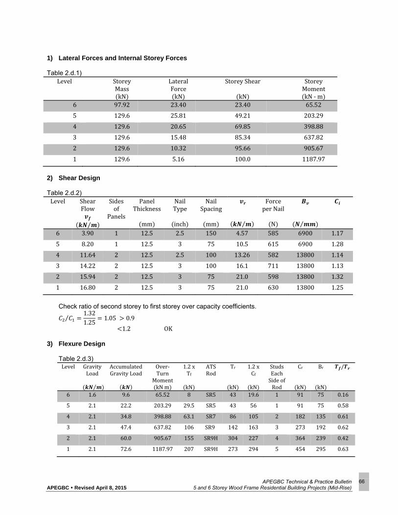
APEGBC Technical & Practice Bulletin APEGBC Revised April 8, 2015 5 and 6 Storey Wood Frame Residential Building Projects (Mid-Rise)
66
1) Lateral Forces and Internal Storey Forces Table 2.d.1)
Level StoreyMasskN
LateralForcekN
StoreyShear
kN
StoreyMomentkN‐m
6 97.92 23.40 23.40 65.52
5 129.6 25.81 49.21 203.29
4 129.6 20.65 69.85 398.88
3 129.6 15.48 85.34 637.82
2 129.6 10.32 95.66 905.67
1 129.6 5.16 100.0 1187.97
2) Shear Design Table 2.d.2) Level Shear
Flow⁄
Sidesof
Panels
PanelThickness
mm
NailType
inch
NailSpacing
mm ⁄
ForceperNail
N
⁄ 6 3.90 1 12.5 2.5 150 4.57 585 6900 1.17
5 8.20 1 12.5 3 75 10.5 615 6900 1.28
4 11.64 2 12.5 2.5 100 13.26 582 13800 1.14
3 14.22 2 12.5 3 100 16.1 711 13800 1.13
2 15.94 2 12.5 3 75 21.0 598 13800 1.32
1 16.80 2 12.5 3 75 21.0 630 13800 1.25
Check ratio of second storey to first storey over capacity coefficients.
⁄1.321.25
1.05 0.9
1.2 OK3) Flexure Design Table 2.d.3)
Level GravityLoad⁄
AccumulatedGravityLoad
Over‐Turn
MomentkNm
1.2xTf
kN
ATSRod
Tr
kN
1.2xCf
kN
StudsEachSideofRod
Cr
kN
Br
kN
/
6 1.6 9.6 65.52 8 SR5 43 19.6 1 91 75 0.16
5 2.1 22.2 203.29 29.5 SR5 43 56 1 91 75 0.58
4 2.1 34.8 398.88 63.1 SR7 86 105 2 182 135 0.61
3 2.1 47.4 637.82 106 SR9 142 163 3 273 192 0.62
2 2.1 60.0 905.67 155 SR9H 304 227 4 364 239 0.42
1 2.1 72.6 1187.97 207 SR9H 273 294 5 454 295 0.63

APEGBC Technical & Practice Bulletin APEGBC Revised April 8, 2015 5 and 6 Storey Wood Frame Residential Building Projects (Mid-Rise)
67
Note: When select ATS roads, dropping of stiffness from upper floor to lower floor is not recommended.
This could happen when choose, saySR7Hfor level 2 and SR9 for level 3. AlthoughTr Level3 165.46kN 1.2Tf 155kN,the stiffness of rod for level 2 drops by 40% 9/8”rodv.s7/8”rod
At level 1 where ATS rod will be anchored into foundation, Tr will be governed by anchorage capacities.
For a typical apartment building with normal storey height, bearing of studs on wood plate will govern the size and number of end studs in compression. For ground level, D.Fir plate may be used since the plate will be pressure treated and with reduced bearing capacity.
Value of Tf/Tr will be used to calculate the real hold down slip given the assumed maximal slip at the full tie down rod capacity and linear variation of the slip based on the stress level of the tie down rod.
e. Deflection Calculation and Rational Calculation of Fundamental Period 1) Sectional bending stiffness of shearwall with ATS hold-down system (refer to page 77) Level 6 For ATS SR5 ⅝”ΦRod ,Ag 198mm2, Ae 146mm2 (refer to Table 12.3 of Concrete
Design Handbook, 3rd Ed.) Ar 0.4Ag 0.6Ae 166.8mm2 Astuds 2x38x140 10640mm2 2–2x6studs jd Lw–2h–g 6000–2x38–152 5772mm
/ 200,000/9500 400/19
y2 n⋅Ar⋅jd/ n⋅Ar 2bh
40019
166.8 5772/40019
166.8 2 140 38 1432.27
y1 jd–y2 4339.73mm
∙ 2 ∙ 200,000 166.8 4339.73 9500 10640 1432.27 8.36 10 ∙
Compare to
2
1064057722
9500 16.83 10 ∙
The sectional bending stiffness will be over estimated by 100%.

APEGBC Technical & Practice Bulletin APEGBC Revised April 8, 2015 5 and 6 Storey Wood Frame Residential Building Projects (Mid-Rise)
68
Table 2.e.1) shows sectional bending stiffness of shearwalls for other levels. Table 2.e.1) – Sectional Bending Stiffness of Shearwall Storey jd
mm Astudsmm2
Agmm2
Aemm2
Armm2
y1mm
y2mm
EI eff
N‐mm2 x1014
6 5772 10640 198 146 166.8 4339.73 1432.27 8.36
5 5772 10640 198 146 166.8 4339.73 1432.27 8.36
4 5696 21280 388 298 334.0 4291.32 1414.68 16.30
3 5620 31920 641 492 551.6 4120.83 1499.17 25.50
2 5544 42560 641 492 551.6 4355.57 1188.43 26.60
1 5468 53200 641 492 551.6 4488.29 979.71 27.10
2) Shearwall Deflection Due to Overall Bending
Refer to formulas on page 76
∆2
3
2. . 1 &
0 2800
2 8.36 10 23.4 10 28003 8.36 10 0.205
2
65.52 10 2800
8.36 1049.21 10 28002 8.36 10
4.5 10
∆i and i for other levels are shown in Table 2.e.2)
Table 2.e.2).1 ∆i and i
Level ∆imm
iradx10‐4
6 0.205 Noneedtocalculate
5 0.738 4.504
4 0.803 5.175
3 0.856 5.681
2 1.201 8.112
1 1.584 10.83
Refer to formulas on page 77
∆ ∆
0.205 2800 4.504 5.175 5.681 8.112 10.83 10 9.81

APEGBC Technical & Practice Bulletin APEGBC Revised April 8, 2015 5 and 6 Storey Wood Frame Residential Building Projects (Mid-Rise)
69
Table 2.e.2).2 shows shearwall deflections due to overall bending at each level. Table 2.e.2).2 - Deflection Due to Bending
Level InterstoreyDriftmm
TotalDriftmm
6 9.81 38.56
5 9.08 28.75
4 7.70 19.67
3 6.16 11.98
2 4.23 5.82
1 1.58 1.58
3) Shearwall Deflection Due to Panel Shear
Refer to page 78 for Level 6,
∆ ∙
,3.9
28006900
1.58
Table 2.3.3) shows shearwall deflections due to panel shear at each level.
Table 2.e.3) - Deflection Due to Panel Shear
Level InterstoreyDriftmm
TotalDriftmm
6 1.58 16.80
5 3.33 15.22
4 2.36 11.89
3 2.89 9.53
2 3.23 6.64
1 3.41 3.41
4) Shearwall Deflection Due to Nail Slipping
Refer to page 78 and shear design results on Table 2.d.2), for level 6, 2.5” nail with 585 N per nail,
0.64585 500600 500
0.88 0.64 0.844
∆ 0.0025 , 0.0025 2800 0.84 5.91

APEGBC Technical & Practice Bulletin APEGBC Revised April 8, 2015 5 and 6 Storey Wood Frame Residential Building Projects (Mid-Rise)
70
Table 2.e.4) shows shearwall deflections due to nail slipping at each level. Table 2.e.4) - Deflection Due to Nail Slipping
Level InterstoreyDriftmm
TotalDriftmm
6 5.91 32.5
5 4.83 26.6
4 5.86 21.7
3 6.23 15.9
2 4.59 9.6
1 5.04 5.0
5) Shearwall Deflection Due to Hold-Down Slipping
It is assumed that the maximal slip of ATS system at its full capacity to be 1mm. The actual
value of slip will be proportioned to the real level of stress. For example, at level 1, Tf/Tr 0.63fromTable2.d.3 ,Slip1 0.63x1mm 0.63mm
∆ 0.636000
2800 0.294
Refer to page 79, ∆
0.63 0.42 0.49 ,so forth.
Table 2.e.5) shows shearwall deflections due to hold-down slipping at each level. Table 2.e.5) - Deflection Due to Hold-Down Slipping
Level InterstoreyDriftmm
TotalDriftmm
6 1.41 5.39
5 1.34 3.97
4 1.07 2.64
3 0.78 1.57
2 0.49 0.79
1 0.29 0.29
6) Drift Limit Check Drift limit is 2.5% for building of normal importance.
∆ 9.81 1.58 5.91 1.41 5.1 95.42
∆ 95.422800
3.4% 2.5%,

APEGBC Technical & Practice Bulletin APEGBC Revised April 8, 2015 5 and 6 Storey Wood Frame Residential Building Projects (Mid-Rise)
71
Table 2.e.6) – Drift Check
Level ∆ DriftRatio Remark
6 95.42 3.4% NG
5 94.74 3.4% NG
4 86.63 3.1% NG
3 81.89 2.9% NG
2 64.03 2.3% OK
1 52.68 1.9% OK
7) Rational Calculation of Fundamental Period
2Σ Δ
Σ ∆ ∆
Where ∆ are the elastic deflections in storey i due to the forces Fi Table 2.e.7)
Level ∆ mm
FikN
Wi
kN
6 93.21 23.4 97.92
5 74.50 25.81 129.60
4 55.93 20.65 129.60
3 38.94 15.48 129.60
2 22.88 10.32 129.60
1 10.33 5.16 129.60
Given g 9.81m/sec2,Ta 1.214sec
Table 2.e.8)
Level ∆ibending
∆ishear
∆iNail
∆ihold‐down
∆i
6 38.56 16.80 32.5 5.39 93.21
5 28.75 15.22 26.6 3.97 74.50
4 19.67 11.89 21.7 2.64 55.93
3 11.98 9.53 15.9 1.57 38.94
2 5.82 6.64 9.6 0.79 22.88
1 1.58 3.41 5.0 0.29 10.33
Since Ta 1.214 2Tcode 2x0.415 0.83secIn the next step,Vbase(T=0.83)x1.2will be used for strength re-design of shearwall.

APEGBC Technical & Practice Bulletin APEGBC Revised April 8, 2015 5 and 6 Storey Wood Frame Residential Building Projects (Mid-Rise)
72
3. RE-DESIGN OF SHEARWALL
a. Base shear at Tof0.83sec V/W 0.10,J 0.934 (refer to page 85) To avoid soft storey from happening due to higher mode vibration for a six storey shearwall, base shear determined here above will be multiplied by 1.2. i.e. Vd/W 0.10x1.2 0.12forstrengthdesign. Since Ta 0.83 0.7,Ft needs to be considered. Ft 0.07TaV 0.25V 0.0581VV–Ft 0.9419V
Overturn Moment reductions due to higher mode also apply. Refer to pages 86 to 89 for lateral force calculations, shear design, flexure design, deflection calculations and period calculation. The following tables present the results of the above calculations. Table 3.a.2 – Shear Design Level Sidesof
PanelsPanel
Thicknessmm
NailType
inch
NailSpacingmm
ShearResistanceVr kN/m
ShearFlow
Vf kN/m
Vr/Vf
Ci6 1 12.5 2.5 150 4.57 4.12 1.11
5 1 12.5 3.0 100 8.05 7.72 1.04
4 2 12.5 3.0 150 10.82 10.59 1.02
3 2 12.5 2.5 100 13.26 12.75 1.04
2 2 12.5 3.0 100 16.10 14.19 1.13
1 2 12.5 3.0 100 16.10 14.19 1.08
C2/C1 1.13/1.08 1.05 0.9 1.2 OK
Table 3.a.1 – Lateral Force and Interstorey Forces BaseShear 0.12W 89.43kN
Level LateralForce kN
StoreyBaseShear
kN
Jx StoreyOver‐turnMomentxJx kN‐ m
6 24.74 24.74 1.0 69.29
5 21.56 46.31 1.0 198.94
4 17.25 63.56 1.0 376.90
3 12.94 76.49 0.99 584.59
2 8.62 85.12 0.97 805.11
1 4.31 89.43 0.95 1028.39

APEGBC Technical & Practice Bulletin APEGBC Revised April 8, 2015 5 and 6 Storey Wood Frame Residential Building Projects (Mid-Rise)
73
Table 3.a.3 – Flexure Design Level ATSRod NumberofStudEach
SideofRod6 SR5 1
5 SR5 1
4 SR7 2
3 SR9 3
2 SR9 4
1 SR9H 5
Table 3.a.4 – Drift Level ∆ DriftRatio Remark
6 96.61 3.5% N.G.
5 103.85 3.7% N.G.
4 92.79 3.3% N.G.
3 82.29 2.9% N.G.
2 69.13 2.5% OK
1 59.10 2.1% OK
Ta 1.31secBy Clause 4.1.8.11.3) for the purpose of calculating the deflections, the period without upper limit may be used.
b. Calculations show that the period converged to 1.21 sec after three more rounds of runs (round 2a, round 2b and round 2c). See pages 91 to 108 for detailed calculations. Table 3.b.1 - Periods of Several Runs round Period
sec PhaseofShearWallDesign
1 1.214 1
2 1.311 2
2a 1.208 2
2b 1.213 2
2c 1.213 2
Periodconverged

APEGBC Technical & Practice Bulletin APEGBC Revised April 8, 2015 5 and 6 Storey Wood Frame Residential Building Projects (Mid-Rise)
74
Table 3.b.2 - Drift Ratio at the End of Deflection Runs Level ∆
mm DriftRatio Remark
6 53.32 1.9% OK
5 54.97 2.0% OK
4 47.33 1.7% OK
3 42.35 1.5% OK
2 35.46 1.3% OK
1 28.63 1.0% OK
4. DIAPHRAGM DESIGN
The tributary area ratio for shearwall “A” over the whole floor area is 72m2/1748m2 = 4.119%. Proportion lateral forces in Table 3.a.1 to the whole building we’ve got, Table 4.1 Level StoreyLateral
ForceforShearwalls
kN
ShearwallOverCapacityration,CifromTable3.a.2
StoreyLateralForceforDiaphragms
kN
6 602 1.11 668
5 523 1.04 544
4 419 1.02 427
3 314 1.04 327
2 209 1.13 236
1 105 1.08 113
Since VTotal 0.12W 2172kNVTotal/6 362kNis the minimal diaphragm design force. The diaphragm design forces are, Table 4.2 Level Diaphragm
Force kN UnitAreaForce kPa
6 668 0.382
5 544 0.311
4 427 0.244
3 362 0.207
2 362 0.207
1 362 0.207
Note: Floor area = 1748 m2 Design of cantilevered diaphragm at level 6. Span 13.3mx2 26.6m

APEGBC Technical & Practice Bulletin APEGBC Revised April 8, 2015 5 and 6 Storey Wood Frame Residential Building Projects (Mid-Rise)
75
W 0.382kPax28m 10.7kN/mM x10.7x26.62 947kN/m
Chordforce 1.2x 1.2x 41kN Try 2 – 38 x 140 chord SPF No. 1 or 2 Tr ΦFtAnKzt0.9x 1.15x1x1x1x5.5MPa x38x140x2x1.378kN 41kN OK
Design of Chord Splice Try steel straps CMST12x8’ long each side by Simpson, Tr 51.74kN Tf 41kN OK
Shear: Vf 13.3mx10.7kN/m /28m 5.1kN/mUse12.5mmDF‐LPLYWOODunblockedwith2.5”nailat150mmatedgesand300mminfieldVr 5.55kN/m Vf 5.1kN/m OK
CMST 12 Each Side

APEGBC Technical & Practice Bulletin APEGBC Revised April 8, 2015 5 and 6 Storey Wood Frame Residential Building Projects (Mid-Rise)
76
∆i
Leveli‐1Mi 1xHi
½ViH2i
Mi 1
ViHi
EI i
Leveli
Hi
DeflectionduetoMi 1 andViHi
i
i
BMDi
5. DESIGN FORMULAS
Shearwall Design Formulas
i = +
∆ 2
2
23
2
3
Note: jdi to be refined after flexure design of shearwall, assuming jdi 0.95Lw for the initial calculation.
V6 F5 M6 V6H6
V5 F5 V6 M5 V5H5 M6V4 F4 V5 M4 V4H4 M5
V3 F3 V4 M3 V3H3 M4
V2 F2 V3 M2 V2H2 M3
V1 F1 V2 M1 V1H1 M2
EI1
F1
EI2
F2
EI3
F3
EI4
F4
EI5
F5
EI6
F6
P6
P3V4 M4
P5V6
M6
jd1
M3
V1
Jd4
P2
Lw 6.0m
M1
V1
jd2
M2
V1
Jd3
P1
jd5
Jd6
P4V5
M5
H2
H3
H4
Level1
Level2
Level3
W2
W3
W4
H1Ground
W1
Level6
W5
W6
Level4
Level5
H5
H6

APEGBC Technical & Practice Bulletin APEGBC Revised April 8, 2015 5 and 6 Storey Wood Frame Residential Building Projects (Mid-Rise)
77
Drift Calculation Formula (Due to Bending) 0.4 0.6
jd Lw–2h–g,n Es/Ew
2
2
5H6
4 H5 H6
3 H4 H5 H6
1 H2 H3 H4 H5 H6
2 H3 H4 H5 H6
Δ1 Δ2 Δ3
Δ6
Δ4Δ5
1 H2 H3 H4
1 H2 H3
1H2
2H3
2 H3 H4
1 H2 H3 H4 H5
2 H3 H4 H5
3 H4 H5
4H5
H6
H5
H4
H3
H2
H1
Level6
Level4
Level1
Level3
Level2
Ground
Level5
ATSHold‐DownSystem
Ar Es
C.G.
y2y1jd
g hh
b

APEGBC Technical & Practice Bulletin APEGBC Revised April 8, 2015 5 and 6 Storey Wood Frame Residential Building Projects (Mid-Rise)
78
Δ1
Δ2
Δ3
Δ4
Δ5
Δ6Level6
Level3
Level4
Level5
Level2
Ground
Level1
H6
H5
H4
H3
H2
H1
H4
H3
H6
H5
Drift Calculation Formula (Due to Panel Shear)
/ ,
∆
Drift Calculation Formula (Due to Nail Slip)
∆ 0.0025
∆ ∆
N/Nail en 2.5” nail
(mm)
en
3” nail(mm)
300 0.29 0.23 400 0.46 0.35 500 0.64 0.49 600 0.88 0.66 700 1.21 0.86 800 1.70 1.13 900 2.33 1.48
1000 1.95
Δ1
Δ2
Δ3
Δ4
Δ5
Δ6Level6
Level3
Level4
Level5
Level2
Level1
H6
H5
H4
H3
H2
H1

APEGBC Technical & Practice Bulletin APEGBC Revised April 8, 2015 5 and 6 Storey Wood Frame Residential Building Projects (Mid-Rise)
79
Drift Calculation Formula (Due to Hold-Down Slip)
Max Slip at Full Strength of H.D.
H6
H5
H4
H3
H2
Level6
Level4
Level3
Level2
Level1
Ground
Level5 H6
Slip3 3
2
Slip11
Lw
Slip2
Slip4 4
6
2
1
5
Lw
Slip6
6
5
3
4
Slip5
a a a a a a
a a a a a
a a a a
a a a
a a
a
, 1 for ATS System
Assumedbutneedsconfirmation
a
a
a
a
a
a
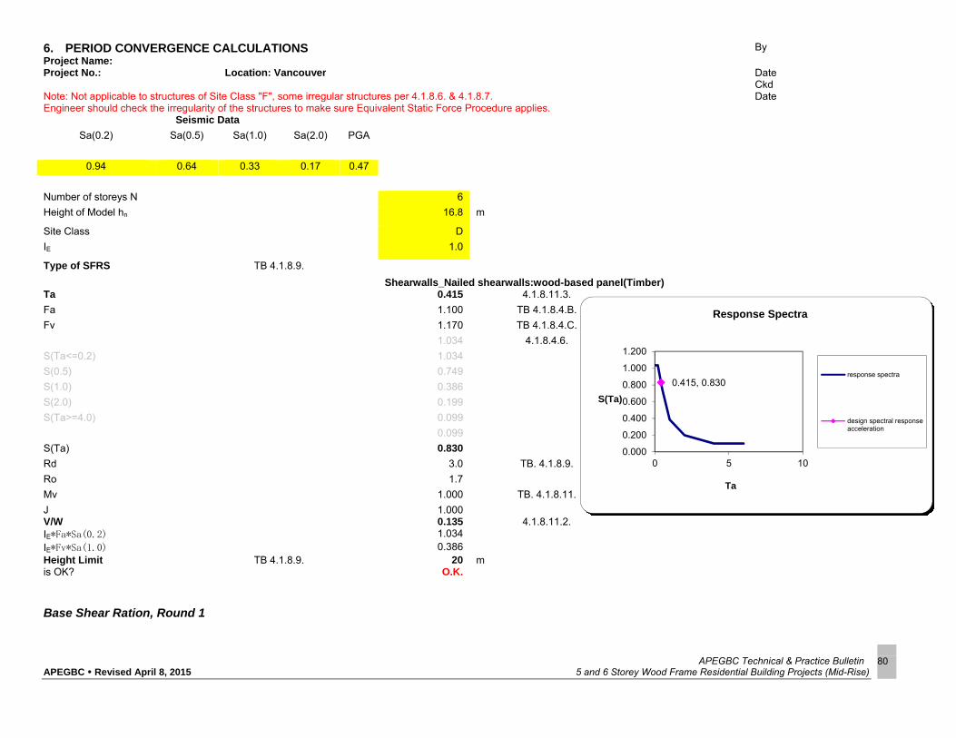
APEGBC Technical & Practice Bulletin APEGBC Revised April 8, 2015 5 and 6 Storey Wood Frame Residential Building Projects (Mid-Rise)
80
Base Shear Ration, Round 1
6. PERIOD CONVERGENCE CALCULATIONS Project Name:
By
Project No.: Location: Vancouver Date Ckd Note: Not applicable to structures of Site Class "F", some irregular structures per 4.1.8.6. & 4.1.8.7. Date Engineer should check the irregularity of the structures to make sure Equivalent Static Force Procedure applies.
Seismic Data
Sa(0.2) Sa(0.5) Sa(1.0) Sa(2.0) PGA
0.94 0.64 0.33 0.17 0.47
Number of storeys N 6
Height of Model hn 16.8 m
Site Class D
IE 1.0
Type of SFRS TB 4.1.8.9.
Shearwalls_Nailed shearwalls:wood-based panel(Timber) Ta 0.415 4.1.8.11.3.
Fa 1.100 TB 4.1.8.4.B.
Fv 1.170 TB 4.1.8.4.C.
1.034 4.1.8.4.6.
S(Ta<=0.2) 1.034
S(0.5) 0.749
S(1.0) 0.386
S(2.0) 0.199
S(Ta>=4.0) 0.099
0.099
S(Ta) 0.830
Rd 3.0 TB. 4.1.8.9.
Ro 1.7
Mv 1.000 TB. 4.1.8.11.
J 1.000 V/W 0.135 4.1.8.11.2. IE*Fa*Sa(0.2) 1.034 IE*Fv*Sa(1.0) 0.386 Height Limit TB 4.1.8.9. 20 m is OK? O.K.
0.415, 0.830
0.000
0.200
0.400
0.600
0.800
1.000
1.200
0 5 10
S(Ta)
Ta
Response Spectra
response spectra
design spectral responseacceleration

APEGBC Technical & Practice Bulletin APEGBC Revised April 8, 2015 5 and 6 Storey Wood Frame Residential Building Projects (Mid-Rise)
81
Shearwall Design, Round 1
design parametres Lw 6.00 m length of shearwall jd_initial 5.70 m assuming jd=0.95Lw for initial calculation V/W 0.135 base shear ratio from the first round calculation ` Tcode = 0.415 sec RdR0 5.100 allowable storey drift ratio = 2.50%
stud size 2x6 single stud area 5320.00 mm2 stud material
SPF
plate material
SPF specified bearing strength
5.30 MPa
lateral force and internal storey forces
storey storey height
(m)
storey mass (kN)
base shear (kN) Wi*Hi Wi*Hi / ∑Wi*Hi
lateral force (kN)
storey base shear
(kN)
storey over-turn moment (kNm)
6 2.80 97.92
100.82
1645.06 0.23 23.40 23.40 65.52 5 2.80 129.60 1814.40 0.26 25.81 49.21 203.29 4 2.80 129.60 1451.52 0.20 20.65 69.85 398.88 3 2.80 129.60 1088.64 0.15 15.48 85.34 637.82 2 2.80 129.60 725.76 0.10 10.32 95.66 905.67 1 2.80 129.60 362.88 0.05 5.16 100.82 1187.97
shear design
storey storey
base shear (kN)
shear flow vf
(kN/m) sides of panels
panel thickness
(mm)
nail type (inch)
nail spacing
(mm)
shear resistance
vr (kN/m)
force per nail (N)
Bv (N/mm)
vr/vf (Ci)
6 23.40 3.90 1 12.50 2.50 150.00 4.57 584.97 6900 1.17 5 49.21 8.20 1 12.50 3.00 75.00 10.50 615.08 6900 1.28 4 69.85 11.64 2 12.50 2.50 100.00 13.26 582.10 13800 1.14 3 85.34 14.22 2 12.50 3.00 100.00 16.10 711.14 13800 1.13 2 95.66 15.94 2 12.50 3.00 75.00 21.00 597.87 13800 1.32 1 100.82 16.80 2 12.50 3.00 75.00 21.00 630.13 13800 1.25
check C2/C1, 0.9<=C2/C1<=1.2 C2/C1= 1.05 OK

APEGBC Technical & Practice Bulletin APEGBC Revised April 8, 2015 5 and 6 Storey Wood Frame Residential Building Projects (Mid-Rise)
82
Shearwall Design, Round 1
flexure design
storey storey
gravity load (kN/m)
accumulated total
gravity load (kN)
storey over-turn moment (kNm)
1.2 Tf (kN)
1.2 Cf (kN)
ATS Rod Tr
(kN)
number of studs each side of rod
Cr (kN)
Br (kN)
Tf/Tr
6 1.60 9.60 65.52 8.03 19.55 SR5 42.45 1 90.89 74.58 0.16 5 2.10 22.20 203.29 29.48 56.12 SR5 42.45 1 90.89 74.58 0.58 4 2.10 34.80 398.88 63.09 104.85 SR7 85.79 2 181.77 134.84 0.61 3 2.10 47.40 637.82 105.84 162.72 SR9 141.96 3 272.66 191.88 0.62 2 2.10 60.00 905.67 154.67 226.67 SR9H 303.74 4 363.54 238.65 0.42 1 2.10 72.60 1187.97 206.54 293.66 SR9H 273.25 5 454.43 295.50 0.63
sectional bending stiffness
storey jd_refined
(mm) Ecmprsn (MPa)
Etnsn (MPa)
Acmprsn (mm2)
Ag (mm2)
Ae (mm2)
Ar (mm2) y1
(mm) y2
(mm) (EI)eff
(N-mm2)
6 5772.00 9500 200000 10640 198.00 146.00 166.80 4339.73 1432.27 8.36E+14 5 5772.00 9500 200000 10640 198.00 146.00 166.80 4339.73 1432.27 8.36E+14 4 5696.00 9500 200000 21280 388.00 298.00 334.00 4281.32 1414.68 1.63E+15 3 5620.00 9500 200000 31920 641.00 492.00 551.60 4120.83 1499.17 2.55E+15 2 5544.00 9500 200000 42560 641.00 492.00 551.60 4355.57 1188.43 2.66E+15 1 5468.00 9500 200000 53200 641.00 492.00 551.60 4488.29 979.71 2.71E+15
shearwall deflection due to overall bending
storey storey
height (m)
storey base shear
(kN)
storey over-turn moment (kNm)
(EI)eff (N-mm2)
ΘMstorey
(rad) ∆Mstorey
(mm) (∆Mi+Hi∑Θi)storey
(mm) ∆Mtotal
(mm)
6 2.80 23.40 65.52 8.36E+14 0.205 9.81 38.56 5 2.80 49.21 203.29 8.36E+14 4.504E-04 0.738 9.08 28.75 4 2.80 69.85 398.88 1.63E+15 5.175E-04 0.803 7.70 19.67 3 2.80 85.34 637.82 2.55E+15 5.681E-04 0.856 6.16 11.98 2 2.80 95.66 905.67 2.66E+15 8.112E-04 1.201 4.23 5.82 1 2.80 100.82 1187.97 2.71E+15 1.083E-03 1.584 1.58 1.58

APEGBC Technical & Practice Bulletin APEGBC Revised April 8, 2015 5 and 6 Storey Wood Frame Residential Building Projects (Mid-Rise)
83
shearwall deflection due to panel shear
storey storey height
(m)
shear flow vf
(kN/m)
Bv (N/mm)
∆Vstorey
(mm) ∆Vtotal
(mm)
6 2.80 3.90 6900 1.58 16.80 5 2.80 8.20 6900 3.33 15.22 4 2.80 11.64 13800 2.36 11.89 3 2.80 14.22 13800 2.89 9.53 2 2.80 15.94 13800 3.23 6.64 1 2.80 16.80 13800 3.41 3.41
shearwall deflection due to nail slipping
storey storey height
(m)
force per nail (N)
nail type (inch)
en25 en30 en ∆en storey (mm)
∆en total
(mm)
6 2.80 584.97 2.50 0.84 0.63 0.84 5.91 32.465 5 2.80 615.08 3.00 0.93 0.69 0.69 4.83 26.557 4 2.80 582.10 2.50 0.84 0.63 0.84 5.86 21.726 3 2.80 711.14 3.00 1.26 0.89 0.89 6.23 15.867 2 2.80 597.87 3.00 0.87 0.66 0.66 4.59 9.637 1 2.80 630.13 3.00 0.98 0.72 0.72 5.04 5.042
shearwall deflection due to hold down slipping
storey storey height
(m)
hold down system
max hold down slip
(mm)
proportioned hold down
slip (mm)
α (rad)
αaccumulated
(rad) ∆hd slp storey
(mm) ∆hd slp total
(mm)
6 2.80 SR5 1.00 0.16 2.63E-05 5.04E-04 1.41 5.385 5 2.80 SR5 1.00 0.58 9.64E-05 4.78E-04 1.34 3.974 4 2.80 SR7 1.00 0.61 1.02E-04 3.81E-04 1.07 2.636 3 2.80 SR9 1.00 0.62 1.04E-04 2.79E-04 0.78 1.568 2 2.80 SR9H 1.00 0.42 7.07E-05 1.76E-04 0.49 0.786 1 2.80 SR9H 1.00 0.63 1.05E-04 1.05E-04 0.29 0.294
Shearwall Design, Round 1

APEGBC Technical & Practice Bulletin APEGBC Revised April 8, 2015 5 and 6 Storey Wood Frame Residential Building Projects (Mid-Rise)
84
shearwall storey drift and drift ratio
storey storey height
(m)
(∆Mi+Hi∑Θi)storey
(mm) ∆Vstorey
(mm) ∆en storey (mm)
∆hd slp storey (mm)
∆storey
(mm)
∆storey x RdR0 (mm)
drift ratio
6 2.80 9.81 1.58 5.91 1.41 18.71 95.42 3.4% no good 5 2.80 9.08 3.33 4.83 1.34 18.58 94.74 3.4% no good 4 2.80 7.70 2.36 5.86 1.07 16.99 86.63 3.1% no good 3 2.80 6.16 2.89 6.23 0.78 16.06 81.89 2.9% no good 2 2.80 4.23 3.23 4.59 0.49 12.55 64.03 2.3% ok 1 2.80 1.58 3.41 5.04 0.29 10.33 52.68 1.9% ok
shearwall total deflection at storey level
storey storey level
(m) ∆Mtotal (mm)
∆Vtotal
(mm) ∆en total
(mm) ∆hd slp total
(mm) ∆total
(mm)
lateral force (kN)
seismic weight (kN)
period (sec)
6 16.80 38.56 16.80 32.46 5.39 93.21 23.40 97.92
1.214
5 14.00 28.75 15.22 26.56 3.97 74.50 25.81 129.60 4 11.20 19.67 11.89 21.73 2.64 55.93 20.65 129.60 3 8.40 11.98 9.53 15.87 1.57 38.94 15.48 129.60 2 5.60 5.82 6.64 9.64 0.79 22.88 10.32 129.60 1 2.80 1.58 3.41 5.04 0.29 10.33 5.16 129.60
alternative calculation of the fundamental period 2/3 building height = 11.20 m ∆2/3 building height = 55.93 mm VD = 100.82 kN g = 9.81 m/s2 W = 745.92 kN K = 1802.77 kN/m T = 1.29 second
Shearwall Design, Round 1

APEGBC Technical & Practice Bulletin APEGBC Revised April 8, 2015 5 and 6 Storey Wood Frame Residential Building Projects (Mid-Rise)
85
Base Shear Ration, Round 2
Project Name: By Project No.: Location: Vancouver Date
Ckd Note: Not applicable to structures of Site Class "F", some irregular structures per 4.1.8.6. & 4.1.8.7. Date Engineer should check the irregularity of the structures to make sure Equivalent Static Force Procedure applies.
Seismic Data Sa(0.2) Sa(0.5) Sa(1.0) Sa(2.0) PGA
0.94 0.64 0.33 0.17 0.47 Number of storeys N 6 Height of Model hn 16.8 m Site Class D IE 1
Type of SFRS TB 4.1.8.9.
Shearwalls_Nailed shearwalls:wood-based panel(Timber)
Ta 0.830 4.1.8.11.3.
Fa 1.100 TB 4.1.8.4.B.
Fv 1.170 TB 4.1.8.4.C.
1.034
4.1.8.4.6.
S(Ta<=0.2) 1.034
S(0.5) 0.749
S(1.0) 0.386
S(2.0) 0.199
S(Ta>=4.0) 0.099
0.099
S(Ta) 0.510
Rd 3.0 TB. 4.1.8.9.
Ro 1.7
Mv 1.000 TB. 4.1.8.11.
J 0.934
V/W 0.100 4.1.8.11.2.
IE*Fa*Sa(0.2) 1.034
IE*Fv*Sa(1.0) 0.386
Height Limit TB 4.1.8.9. 20 m
is OK? O.K.
0.415, 0.830
0.000
0.200
0.400
0.600
0.800
1.000
1.200
0 5 10
S(Ta)
Ta
Response Spectra
response spectra
design spectral responseacceleration

APEGBC Technical & Practice Bulletin APEGBC Revised April 8, 2015 5 and 6 Storey Wood Frame Residential Building Projects (Mid-Rise)
86
Shearwall design, Round 2
design parametres Lw 6.00 m length of shearwall 2* Tcode 0.830
0.830 jd_initial 5.70 m assuming jd=0.95Lw for initial calculation Tround1 1.214
V/W 0.100 base shear ratio from the second round calculation moment reduction factor due to high mode
RdR0 5.100 allowable storey drift ratio = 2.50% J= 0.934
stud size 2x6 single stud area 5320.00 mm2 stud material
SPF
plate material
SPF specified bearing strength
5.30 MPa
lateral force and internal storey forces
storey storey height
(m) storey mass (kN)
base shear x 1.2 (kN)
Wi * Hi Wi*Hi / ∑Wi*Hi
lateral force (kN)
storey base shear (kN)
level height
(m) Jx
storey over-turn moment (kNm)
storey over-turn moment *
Jx (kNm)
6 2.80 97.92
89.43
1645.06 0.23 24.74 24.74 16.80 1.00 69.29 69.29 5 2.80 129.60 1814.40 0.26 21.56 46.31 14.00 1.00 198.94 198.94 4 2.80 129.60 1451.52 0.20 17.25 63.56 11.20 1.00 376.90 376.90 3 2.80 129.60 1088.64 0.15 12.94 76.49 8.40 0.99 591.09 584.59 2 2.80 129.60 725.76 0.10 8.62 85.12 5.60 0.97 829.42 805.11 1 2.80 129.60 362.88 0.05 4.31 89.43 2.80 0.95 1079.83 1028.39
shear design
storey storey
base shear (kN)
shear flow vf (kN/m)
sides of panels
panel thickness
(mm)
nail type (inch)
nail spacing
(mm)
shear resistance
vr (kN/m)
force per nail (N)
Bv (N/mm)
vr/vf (Ci)
6 24.74 4.12 1 12.50 2.50 150.00 4.57 618.62 6900 1.11 5 46.31 7.72 1 12.50 3.00 100.00 8.05 771.78 6900 1.04 4 63.56 10.59 2 12.50 3.00 150.00 10.82 794.46 13800 1.02 3 76.49 12.75 2 12.50 2.50 100.00 13.26 637.45 13800 1.04 2 85.12 14.19 2 12.50 3.00 100.00 16.10 709.33 13800 1.13 1 89.43 14.91 2 12.50 3.00 100.00 16.10 745.26 13800 1.08
check C2/C1, 0.9<=C2/C1<=1.2 C2/C1= 1.05 OK

APEGBC Technical & Practice Bulletin APEGBC Revised April 8, 2015 5 and 6 Storey Wood Frame Residential Building Projects (Mid-Rise)
87
flexure design
storey storey
gravity load (kN/m)
accumulated total
gravity load (kN)
storey over-turn moment
(kNm)
1.2 Tf (kN)
1.2 Cf (kN)
ATS Rod Tr
(kN)
number of studs each side of rod
Cr (kN)
Br (kN)
Tf/Tr
6 1.60 9.60 69.29 8.83 20.35 SR5 42.45 1 90.89 74.58 0.17 5 2.10 22.20 198.94 28.56 55.20 SR5 42.45 1 90.89 74.58 0.56 4 2.10 34.80 376.90 58.47 100.23 SR7 85.79 2 181.77 134.84 0.57 3 2.10 47.40 584.59 94.63 151.51 SR9 141.96 3 272.66 191.88 0.56 2 2.10 60.00 805.11 133.50 205.50 SR9 141.96 4 363.54 238.65 0.78 1 2.10 72.60 1028.39 172.94 260.06 SR9H 273.25 5 454.43 295.50 0.53
sectional bending stiffness
storey jd_refined
(mm) Ecmprsn (MPa)
Etnsn (MPa)
Acmprsn (mm2)
Ag (mm2)
Ae (mm2)
Ar (mm2) y1
(mm) y2
(mm) (EI)eff
(N-mm2)
6 5772.00 9500 200000 10640 198.00 146.00 166.80 4339.73 1432.27 8.36E+14 5 5772.00 9500 200000 10640 198.00 146.00 166.80 4339.73 1432.27 8.36E+14 4 5696.00 9500 200000 21280 388.00 298.00 334.00 4281.32 1414.68 1.63E+15 3 5620.00 9500 200000 31920 641.00 492.00 551.60 4120.83 1499.17 2.55E+15 2 5544.00 9500 200000 42560 641.00 492.00 551.60 4355.57 1188.43 2.66E+15 1 5468.00 9500 200000 53200 641.00 492.00 551.60 4488.29 979.71 2.71E+15
shearwall deflection due to overall bending
storey storey
height (m)
storey base shear
(kN)
storey over-turn moment
(kNm)
(EI)eff (N-mm2)
ΘMstorey
(rad) ∆Mstorey
(mm) (∆Mi+Hi∑Θi)storey
(mm) ∆Mtotal
(mm)
6 2.80 24.74 69.29 8.36E+14 0.217 9.20 35.72 5 2.80 46.31 198.94 8.36E+14 4.494E-04 0.731 8.46 26.52 4 2.80 63.56 376.90 1.63E+15 4.949E-04 0.764 7.10 18.07 3 2.80 76.49 591.09 2.55E+15 5.304E-04 0.797 5.65 10.96 2 2.80 85.12 829.42 2.66E+15 7.465E-04 1.104 3.87 5.31 1 2.80 89.43 1079.83 2.71E+15 9.873E-04 1.443 1.44 1.44
Shearwall design, Round 2

APEGBC Technical & Practice Bulletin APEGBC Revised April 8, 2015 5 and 6 Storey Wood Frame Residential Building Projects (Mid-Rise)
88
shearwall deflection due to panel shear
storey storey height
(m)
shear flow vf
(kN/m)
Bv (N/mm)
∆Vstorey
(mm) ∆Vtotal
(mm)
6 2.80 4.12 6900 1.67 15.44 5 2.80 7.72 6900 3.13 13.77 4 2.80 10.59 13800 2.15 10.64 3 2.80 12.75 13800 2.59 8.49 2 2.80 14.19 13800 2.88 5.90 1 2.80 14.91 13800 3.02 3.02
shearwall deflection due to nail slipping
storey storey height
(m)
force per nail (N)
nail type (inch)
en25 en30 en ∆en storey (mm)
∆en total
(mm)
6 2.80 618.62 2.50 0.94 0.70 0.94 6.59 41.869 5 2.80 771.78 3.00 1.56 1.05 1.05 7.38 35.279 4 2.80 794.46 3.00 1.67 1.12 1.12 7.81 27.902 3 2.80 637.45 2.50 1.00 0.73 1.00 7.03 20.097 2 2.80 709.33 3.00 1.26 0.89 0.89 6.20 13.072 1 2.80 745.26 3.00 1.43 0.98 0.98 6.88 6.875
shearwall deflection due to hold down slipping
storey storey height
(m)
hold down system
max hold down slip
(mm)
proportioned hold down
slip (mm)
α (rad)
αaccumulated
(rad) ∆hd slp storey
(mm) ∆hd slp total
(mm)
6 2.80 SR5 1.00 0.17 2.89E-05 5.28E-04 1.48 5.742 5 2.80 SR5 1.00 0.56 9.35E-05 4.99E-04 1.40 4.263 4 2.80 SR7 1.00 0.57 9.47E-05 4.06E-04 1.14 2.865 3 2.80 SR9 1.00 0.56 9.26E-05 3.11E-04 0.87 1.729 2 2.80 SR9 1.00 0.78 1.31E-04 2.19E-04 0.61 0.858 1 2.80 SR9H 1.00 0.53 8.79E-05 8.79E-05 0.25 0.246
Shearwall design, Round 2
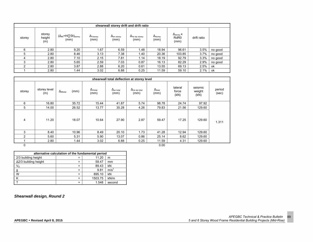
APEGBC Technical & Practice Bulletin APEGBC Revised April 8, 2015 5 and 6 Storey Wood Frame Residential Building Projects (Mid-Rise)
89
shearwall storey drift and drift ratio
storey storey height
(m)
(∆Mi+Hi∑Θi)storey
(mm) ∆Vstorey
(mm) ∆en storey (mm)
∆hd slp storey (mm)
∆storey
(mm)
∆storey x RdR0 (mm)
drift ratio
6 2.80 9.20 1.67 6.59 1.48 18.94 96.61 3.5% no good 5 2.80 8.46 3.13 7.38 1.40 20.36 103.85 3.7% no good 4 2.80 7.10 2.15 7.81 1.14 18.19 92.79 3.3% no good 3 2.80 5.65 2.59 7.03 0.87 16.13 82.29 2.9% no good 2 2.80 3.87 2.88 6.20 0.61 13.55 69.13 2.5% ok 1 2.80 1.44 3.02 6.88 0.25 11.59 59.10 2.1% ok
shearwall total deflection at storey level
storey storey level
(m) ∆Mtotal (mm)
∆Vtotal
(mm) ∆en total
(mm) ∆hd slp total
(mm) ∆total
(mm)
lateral force (kN)
seismic weight (kN)
period (sec)
6 16.80 35.72 15.44 41.87 5.74 98.78 24.74 97.92
1.311
5 14.00 26.52 13.77 35.28 4.26 79.83 21.56 129.60
4 11.20 18.07 10.64 27.90 2.87 59.47 17.25 129.60
3 8.40 10.96 8.49 20.10 1.73 41.28 12.94 129.60 2 5.60 5.31 5.90 13.07 0.86 25.14 8.62 129.60 1 2.80 1.44 3.02 6.88 0.25 11.59 4.31 129.60 0 0.00
alternative calculation of the fundamental period 2/3 building height = 11.20 m ∆2/3 building height = 59.47 mm VD = 89.43 kN g = 9.81 m/s2 W = 895.10 kN K = 1503.75 kN/m T = 1.548 second
Shearwall design, Round 2

APEGBC Technical & Practice Bulletin APEGBC Revised April 8, 2015 5 and 6 Storey Wood Frame Residential Building Projects (Mid-Rise)
90
storey storey height
(m)
panel thickness
(mm)
Bv (N/mm)
∆V+en
storey (mm)
shear flow vf
(kN/m)
Av (mm2)
G (MPa)
6 2.80 12.50 6900 8.26 4.12 1.44E+04 552.00
5 2.80 12.50 6900 10.51 7.72 2.12E+04 552.00
4 2.80 12.50 13800 9.95 10.59 1.54E+04 1104.00
3 2.80 12.50 13800 9.61 12.75 1.92E+04 1104.00
2 2.80 12.50 13800 9.07 14.19 2.26E+04 1104.00
1 2.80 12.50 13800 9.90 14.91 2.18E+04 1104.00
storey α
(rad)
storey over-turn moment
* Jx (kNm)
rotional spring
(kNm/rad)
Etnsn (MPa)
(EI)eff (N-mm2)
Ieff (mm4)
6 2.89E-
05 69.29 2.40E+06 9500.00 8.36E+14 8.80E+10
5 9.35E-
05 198.94 2.13E+06 9500.00 8.36E+14 8.80E+10
4 9.47E-
05 376.90 3.98E+06 9500.00 1.63E+15 1.71E+11
3 9.26E-
05 584.59 6.31E+06 9500.00 2.55E+15 2.69E+11
2 1.31E-
04 805.11 6.16E+06 9500.00 2.66E+15 2.80E+11
1 8.79E-
05 1028.39 1.17E+07 9500.00 2.71E+15 2.85E+11
Shearwall design, Round 2
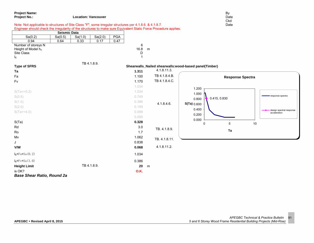
APEGBC Technical & Practice Bulletin APEGBC Revised April 8, 2015 5 and 6 Storey Wood Frame Residential Building Projects (Mid-Rise)
91
Base Shear Ratio, Round 2a
Project Name: By Project No.: Location: Vancouver Date
Ckd Note: Not applicable to structures of Site Class "F", some irregular structures per 4.1.8.6. & 4.1.8.7. Date Engineer should check the irregularity of the structures to make sure Equivalent Static Force Procedure applies.
Seismic Data Sa(0.2) Sa(0.5) Sa(1.0) Sa(2.0) PGA
0.94 0.64 0.33 0.17 0.47 Number of storeys N 6 Height of Model hn 16.8 m Site Class D IE 1
Type of SFRS TB 4.1.8.9.
Shearwalls_Nailed shearwalls:wood-based panel(Timber)
Ta 1.311 4.1.8.11.3.
Fa 1.100 TB 4.1.8.4.B.
Fv 1.170 TB 4.1.8.4.C.
1.034
4.1.8.4.6.
S(Ta<=0.2) 1.034
S(0.5) 0.749
S(1.0) 0.386
S(2.0) 0.199
S(Ta>=4.0) 0.099
0.099
S(Ta) 0.328
Rd 3.0 TB. 4.1.8.9.
Ro 1.7
Mv 1.062 TB. 4.1.8.11.
J 0.838
V/W 0.068 4.1.8.11.2.
IE*Fa*Sa(0.2) 1.034
IE*Fv*Sa(1.0) 0.386
Height Limit TB 4.1.8.9. 20 m
is OK? O.K.
0.415, 0.830
0.000
0.200
0.400
0.600
0.800
1.000
1.200
0 5 10
S(Ta)
Ta
Response Spectra
response spectra
design spectral responseacceleration

APEGBC Technical & Practice Bulletin APEGBC Revised April 8, 2015 5 and 6 Storey Wood Frame Residential Building Projects (Mid-Rise)
92
Shearwall Design, Round 2a
design parametres Lw 6.00 m length of shearwall 2* Tcode 0.830
1.311 jd_initial 5.70 m assuming jd=0.95Lw for initial calculation Tround1 1.311
V/W 0.068 base shear ratio from the second round calculation moment reduction factor due to high mode
RdR0 5.100 allowable storey drift ratio = 2.50% J= 0.838
stud size 2x6 single stud area 5320.00 mm2 stud material
SPF
plate material
SPF specified bearing strength
5.30 MPa
lateral force and internal storey forces
storey storey height
(m) storey mass (kN)
base shear (kN)
Wi * Hi Wi*Hi / ∑Wi*Hi
lateral force (kN)
storey base shear (kN)
level height
(m) Jx
storey over-turn moment (kNm)
storey over-turn moment *
Jx (kNm)
6 2.80 97.92
50.93
1645.06 0.23 15.41 15.41 16.80 1.00 43.15 43.15 5 2.80 129.60 1814.40 0.26 11.84 27.25 14.00 1.00 119.46 119.46 4 2.80 129.60 1451.52 0.20 9.47 36.73 11.20 1.00 222.29 222.29 3 2.80 129.60 1088.64 0.15 7.10 43.83 8.40 0.97 345.01 335.68 2 2.80 129.60 725.76 0.10 4.74 48.57 5.60 0.93 481.00 446.32 1 2.80 129.60 362.88 0.05 2.37 50.93 2.80 0.88 623.62 550.55
shear design
storey storey
base shear (kN)
shear flow vf (kN/m)
sides of panels
panel thickness
(mm)
nail type (inch)
nail spacing
(mm)
shear resistance
vr (kN/m)
force per nail (N)
Bv (N/mm)
vr/vf (Ci)
6 15.41 2.57 1 12.50 2.50 150.00 4.57 385.27 6900 1.78 5 27.25 4.54 1 12.50 3.00 100.00 8.05 454.20 6900 1.77 4 36.73 6.12 2 12.50 3.00 150.00 10.82 459.07 13800 1.77 3 43.83 7.31 2 12.50 2.50 100.00 13.26 365.25 13800 1.82 2 48.57 8.09 2 12.50 3.00 100.00 16.10 404.72 13800 1.99 1 50.93 8.49 2 12.50 3.00 100.00 16.10 424.46 13800 1.90
check C2/C1, 0.9<=C2/C1<=1.2 C2/C1= 1.05 OK

APEGBC Technical & Practice Bulletin APEGBC Revised April 8, 2015 5 and 6 Storey Wood Frame Residential Building Projects (Mid-Rise)
93
Shearwall Design, Round 2a
flexure design
storey storey
gravity load (kN/m)
accumulated total
gravity load (kN)
storey over-turn moment
(kNm)
1.2 Tf (kN)
1.2 Cf (kN)
ATS Rod Tr
(kN)
number of studs each side of rod
Cr (kN)
Br (kN)
Tr/Tf
6 1.60 9.60 43.15 3.32 14.84 SR5 42.45 1 90.89 74.58 0.07 5 2.10 22.20 119.46 11.83 38.47 SR5 42.45 1 90.89 74.58 0.23 4 2.10 34.80 222.29 25.92 67.68 SR7 85.79 2 181.77 134.84 0.25 3 2.10 47.40 335.68 42.23 99.11 SR9 141.96 3 272.66 191.88 0.25 2 2.10 60.00 446.32 57.96 129.96 SR9 141.96 4 363.54 238.65 0.34 1 2.10 72.60 550.55 72.34 159.46 SR9H 273.25 5 454.43 295.50 0.22
sectional bending stiffness
storey jd_refined
(mm) Ecmprsn (MPa)
Etnsn (MPa)
Acmprsn (mm2)
Ag (mm2)
Ae (mm2)
Ar (mm2) y1
(mm) y2
(mm) (EI)eff
(N-mm2)
6 5772.00 9500.00 200000.00 10640.00 198.00 146.00 166.80 4339.73 1432.27 8.36E+14 5 5772.00 9500.00 200000.00 10640.00 198.00 146.00 166.80 4339.73 1432.27 8.36E+14 4 5696.00 9500.00 200000.00 21280.00 388.00 298.00 334.00 4281.32 1414.68 1.63E+15 3 5620.00 9500.00 200000.00 31920.00 641.00 492.00 551.60 4120.83 1499.17 2.55E+15 2 5544.00 9500.00 200000.00 42560.00 641.00 492.00 551.60 4355.57 1188.43 2.66E+15 1 5468.00 9500.00 200000.00 53200.00 641.00 492.00 551.60 4488.29 979.71 2.71E+15
shearwall deflection due to overall bending
storey storey
height (m)
storey base shear
(kN)
storey over-turn moment
(kNm)
(EI)eff (N-mm2)
ΘMstorey
(rad) ∆Mstorey
(mm) (∆Mi+Hi∑Θi)storey
(mm) ∆Mtotal
(mm)
6 2.80 15.41 43.15 8.36E+14 0.135 5.41 20.85 5 2.80 27.25 119.46 8.36E+14 2.724E-04 0.441 4.95 15.44 4 2.80 36.73 222.29 1.63E+15 2.937E-04 0.452 4.14 10.49 3 2.80 43.83 345.01 2.55E+15 3.109E-04 0.467 3.28 6.36 2 2.80 48.57 481.00 2.66E+15 4.341E-04 0.641 2.24 3.07 1 2.80 50.93 623.62 2.71E+15 5.712E-04 0.834 0.83 0.83
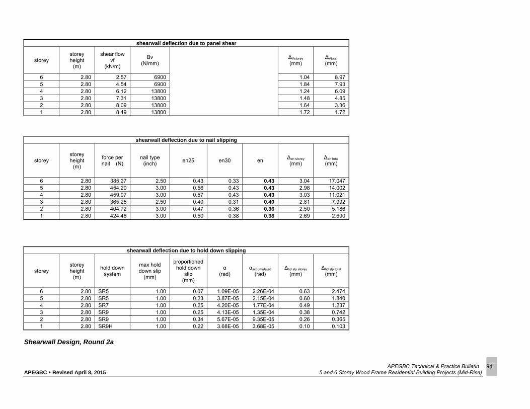
APEGBC Technical & Practice Bulletin APEGBC Revised April 8, 2015 5 and 6 Storey Wood Frame Residential Building Projects (Mid-Rise)
94
shearwall deflection due to panel shear
storey storey height
(m)
shear flow vf
(kN/m)
Bv (N/mm)
∆Vstorey
(mm) ∆Vtotal
(mm)
6 2.80 2.57 6900 1.04 8.97 5 2.80 4.54 6900 1.84 7.93 4 2.80 6.12 13800 1.24 6.09 3 2.80 7.31 13800 1.48 4.85 2 2.80 8.09 13800 1.64 3.36 1 2.80 8.49 13800 1.72 1.72
shearwall deflection due to nail slipping
storey storey height
(m)
force per nail (N)
nail type (inch)
en25 en30 en ∆en storey (mm)
∆en total
(mm)
6 2.80 385.27 2.50 0.43 0.33 0.43 3.04 17.047 5 2.80 454.20 3.00 0.56 0.43 0.43 2.98 14.002 4 2.80 459.07 3.00 0.57 0.43 0.43 3.03 11.021 3 2.80 365.25 2.50 0.40 0.31 0.40 2.81 7.992 2 2.80 404.72 3.00 0.47 0.36 0.36 2.50 5.186 1 2.80 424.46 3.00 0.50 0.38 0.38 2.69 2.690
shearwall deflection due to hold down slipping
storey storey height
(m)
hold down system
max hold down slip
(mm)
proportioned hold down
slip (mm)
α (rad)
αaccumulated
(rad) ∆hd slp storey
(mm) ∆hd slp total
(mm)
6 2.80 SR5 1.00 0.07 1.09E-05 2.26E-04 0.63 2.474 5 2.80 SR5 1.00 0.23 3.87E-05 2.15E-04 0.60 1.840 4 2.80 SR7 1.00 0.25 4.20E-05 1.77E-04 0.49 1.237 3 2.80 SR9 1.00 0.25 4.13E-05 1.35E-04 0.38 0.742 2 2.80 SR9 1.00 0.34 5.67E-05 9.35E-05 0.26 0.365 1 2.80 SR9H 1.00 0.22 3.68E-05 3.68E-05 0.10 0.103
Shearwall Design, Round 2a

APEGBC Technical & Practice Bulletin APEGBC Revised April 8, 2015 5 and 6 Storey Wood Frame Residential Building Projects (Mid-Rise)
95
shearwall storey drift and drift ratio
storey storey height
(m)
(∆Mi+Hi∑Θi)storey
(mm) ∆Vstorey
(mm) ∆en storey (mm)
∆hd slp storey (mm)
∆storey
(mm)
∆storey x RdR0 (mm)
drift ratio
6 2.80 5.41 1.04 3.04 0.63 10.13 51.64 1.8% ok 5 2.80 4.95 1.84 2.98 0.60 10.38 52.92 1.9% ok 4 2.80 4.14 1.24 3.03 0.49 8.90 45.41 1.6% ok 3 2.80 3.28 1.48 2.81 0.38 7.95 40.53 1.4% ok 2 2.80 2.24 1.64 2.50 0.26 6.64 33.87 1.2% ok 1 2.80 0.83 1.72 2.69 0.10 5.35 27.28 1.0% ok
shearwall total deflection at storey level
storey storey level
(m) ∆Mtotal (mm)
∆Vtotal
(mm) ∆en total
(mm) ∆hd slp total
(mm) ∆total
(mm)
lateral force (kN)
seismic weight (kN)
period (sec)
6 16.80 20.85 8.97 17.05 2.47 49.34 15.41 97.92
1.208
5 14.00 15.44 7.93 14.00 1.84 39.22 11.84 129.60 4 11.20 10.49 6.09 11.02 1.24 28.84 9.47 129.60 3 8.40 6.36 4.85 7.99 0.74 19.94 7.10 129.60 2 5.60 3.07 3.36 5.19 0.36 11.99 4.74 129.60 1 2.80 0.83 1.72 2.69 0.10 5.35 2.37 129.60
alternative calculation of the fundamental period 2/3 building height = 11.20 m ∆2/3 building height = 28.84 mm VD = 50.93 kN g = 9.81 m/s2 W = 745.92 kN K = 1766.08 kN/m T = 1.30 second
Shearwall Design, Round 2a

APEGBC Technical & Practice Bulletin APEGBC Revised April 8, 2015 5 and 6 Storey Wood Frame Residential Building Projects (Mid-Rise)
96
Shearwall Design, Round 2a
storey storey height
(m)
panel thickness
(mm)
Bv (N/mm)
∆V+en
storey (mm)
shear flow vf
(kN/m)
Av (mm2)
G (MPa)
6 2.80 12.50 6900 4.09 2.57 1.82E+04 552.00
5 2.80 12.50 6900 4.82 4.54 2.72E+04 552.00
4 2.80 12.50 13800 4.27 6.12 2.07E+04 1104.00
3 2.80 12.50 13800 4.29 7.31 2.46E+04 1104.00
2 2.80 12.50 13800 4.14 8.09 2.83E+04 1104.00
1 2.80 12.50 13800 4.41 8.49 2.78E+04 1104.00
storey α
(rad)
storey over-turn moment
* Jx (kNm)
rotional spring
(kNm/rad)
Etnsn (MPa)
(EI)eff (N-mm2)
Ieff (mm4)
6 1.09E-
05 43.15 3.97E+06 9500.00 8.36E+14 8.80E+10
5 3.87E-
05 119.46 3.09E+06 9500.00 8.36E+14 8.80E+10
4 4.20E-
05 222.29 5.30E+06 9500.00 1.63E+15 1.71E+11
3 4.13E-
05 335.68 8.12E+06 9500.00 2.55E+15 2.69E+11
2 5.67E-
05 446.32 7.87E+06 9500.00 2.66E+15 2.80E+11
1 3.68E-
05 550.55 1.50E+07 9500.00 2.71E+15 2.85E+11

APEGBC Technical & Practice Bulletin APEGBC Revised April 8, 2015 5 and 6 Storey Wood Frame Residential Building Projects (Mid-Rise)
97
Base Shear Ration, Round 2b
Project Name: By Project No.: Location: Vancouver Date
Ckd Note: Not applicable to structures of Site Class "F", some irregular structures per 4.1.8.6. & 4.1.8.7. Date Engineer should check the irregularity of the structures to make sure Equivalent Static Force Procedure applies.
Seismic Data Sa(0.2) Sa(0.5) Sa(1.0) Sa(2.0) PGA
0.94 0.64 0.33 0.17 0.47 Number of storeys N 6 Height of Model hn 16.8 m Site Class D IE 1
Type of SFRS TB 4.1.8.9.
Shearwalls_Nailed shearwalls:wood-based panel(Timber)
Ta 1.208 4.1.8.11.3.
Fa 1.100 TB 4.1.8.4.B.
Fv 1.170 TB 4.1.8.4.C.
1.034
4.1.8.4.6.
S(Ta<=0.2) 1.034
S(0.5) 0.749
S(1.0) 0.386
S(2.0) 0.199
S(Ta>=4.0) 0.099
0.099
S(Ta) 0.347
Rd 3.0 TB. 4.1.8.9.
Ro 1.7
Mv 1.042 TB. 4.1.8.11.
J 0.858
V/W 0.071 4.1.8.11.2.
IE*Fa*Sa(0.2) 1.034
IE*Fv*Sa(1.0) 0.386
Height Limit TB 4.1.8.9. 20 m
is OK? O.K.
0.415, 0.830
0.000
0.200
0.400
0.600
0.800
1.000
1.200
0 5 10
S(Ta)
Ta
Response Spectra
response spectra
design spectral responseacceleration

APEGBC Technical & Practice Bulletin APEGBC Revised April 8, 2015 5 and 6 Storey Wood Frame Residential Building Projects (Mid-Rise)
98
Shearwall Design, Round 2b
design parametres Lw 6.00 m length of shearwall 2* Tcode 0.830
1.208 jd_initial 5.70 m assuming jd=0.95Lw for initial calculation Tround1 1.208
V/W 0.071 base shear ratio from the second round calculation moment reduction factor due to high mode
RdR0 5.100 allowable storey drift ratio = 2.50% J= 0.858
stud size 2x6 single stud area 5320.00 mm2 stud material
SPF
plate material
SPF specified bearing strength
5.30 MPa
lateral force and internal storey forces
storey storey height
(m) storey mass (kN)
base shear (kN)
Wi * Hi Wi*Hi / ∑Wi*Hi
lateral force (kN)
storey base shear (kN)
level height
(m) Jx
storey over-turn moment (kNm)
storey over-turn moment *
Jx (kNm)
6 2.80 97.92
52.89
1645.06 0.23 15.71 15.71 16.80 1.00 43.99 43.99 5 2.80 129.60 1814.40 0.26 12.39 28.10 14.00 1.00 122.68 122.68 4 2.80 129.60 1451.52 0.20 9.92 38.02 11.20 1.00 229.14 229.14 3 2.80 129.60 1088.64 0.15 7.44 45.46 8.40 0.98 356.42 348.01 2 2.80 129.60 725.76 0.10 4.96 50.42 5.60 0.94 497.58 466.28 1 2.80 129.60 362.88 0.05 2.48 52.89 2.80 0.90 645.68 579.69
shear design
storey storey
base shear (kN)
shear flow vf (kN/m)
sides of panels
panel thickness
(mm)
nail type (inch)
nail spacing
(mm)
shear resistance
vr (kN/m)
force per nail (N)
Bv (N/mm)
vr/vf (Ci)
6 15.71 2.62 1 12.50 2.50 150.00 4.57 392.74 6900 1.75 5 28.10 4.68 1 12.50 3.00 100.00 8.05 468.41 6900 1.72 4 38.02 6.34 2 12.50 3.00 150.00 10.82 475.26 13800 1.71 3 45.46 7.58 2 12.50 2.50 100.00 13.26 378.81 13800 1.75 2 50.42 8.40 2 12.50 3.00 100.00 16.10 420.13 13800 1.92 1 52.89 8.82 2 12.50 3.00 100.00 16.10 440.79 13800 1.83
check C2/C1, 0.9<=C2/C1<=1.2 C2/C1= 1.05 OK

APEGBC Technical & Practice Bulletin APEGBC Revised April 8, 2015 5 and 6 Storey Wood Frame Residential Building Projects (Mid-Rise)
99
flexure design
storey storey
gravity load (kN/m)
accumulated total
gravity load (kN)
storey over-turn moment
(kNm)
1.2 Tf (kN)
1.2 Cf (kN)
ATS Rod Tr
(kN)
number of studs each side of rod
Cr (kN)
Br (kN)
Tr/Tf
6 1.60 9.60 43.99 3.50 15.02 SR5 42.45 1 90.89 74.58 0.07 5 2.10 22.20 122.68 12.51 39.15 SR5 42.45 1 90.89 74.58 0.25 4 2.10 34.80 229.14 27.36 69.12 SR7 85.79 2 181.77 134.84 0.27 3 2.10 47.40 348.01 44.83 101.71 SR9 141.96 3 272.66 191.88 0.26 2 2.10 60.00 466.28 62.16 134.16 SR9 141.96 4 363.54 238.65 0.36 1 2.10 72.60 579.69 78.48 165.60 SR9H 273.25 5 454.43 295.50 0.24
sectional bending stiffness
storey jd_refined
(mm) Ecmprsn (MPa)
Etnsn (MPa)
Acmprsn (mm2)
Ag (mm2)
Ae (mm2)
Ar (mm2) y1
(mm) y2
(mm) (EI)eff
(N-mm2)
6 5772.00 9500.00 200000.00 10640.00 198.00 146.00 166.80 4339.73 1432.27 8.36E+14 5 5772.00 9500.00 200000.00 10640.00 198.00 146.00 166.80 4339.73 1432.27 8.36E+14 4 5696.00 9500.00 200000.00 21280.00 388.00 298.00 334.00 4281.32 1414.68 1.63E+15 3 5620.00 9500.00 200000.00 31920.00 641.00 492.00 551.60 4120.83 1499.17 2.55E+15 2 5544.00 9500.00 200000.00 42560.00 641.00 492.00 551.60 4355.57 1188.43 2.66E+15 1 5468.00 9500.00 200000.00 53200.00 641.00 492.00 551.60 4488.29 979.71 2.71E+15
shearwall deflection due to overall bending
storey storey
height (m)
storey base shear
(kN)
storey over-turn moment
(kNm)
(EI)eff (N-mm2)
ΘMstorey
(rad) ∆Mstorey
(mm) (∆Mi+Hi∑Θi)storey
(mm) ∆Mtotal
(mm)
6 2.80 15.71 43.99 8.36E+14 0.138 5.58 21.54 5 2.80 28.10 122.68 8.36E+14 2.792E-04 0.452 5.11 15.96 4 2.80 38.02 229.14 1.63E+15 3.024E-04 0.466 4.28 10.85 3 2.80 45.46 356.42 2.55E+15 3.209E-04 0.482 3.39 6.58 2 2.80 50.42 497.58 2.66E+15 4.488E-04 0.663 2.32 3.18 1 2.80 52.89 645.68 2.71E+15 5.912E-04 0.863 0.86 0.86
Shearwall Design, Round 2b

APEGBC Technical & Practice Bulletin APEGBC Revised April 8, 2015 5 and 6 Storey Wood Frame Residential Building Projects (Mid-Rise)
100
shearwall deflection due to panel shear
storey storey height
(m)
shear flow vf
(kN/m)
Bv (N/mm)
∆Vstorey
(mm) ∆Vtotal
(mm)
6 2.80 2.62 6900 1.06 9.28 5 2.80 4.68 6900 1.90 8.22 4 2.80 6.34 13800 1.29 6.32 3 2.80 7.58 13800 1.54 5.03 2 2.80 8.40 13800 1.70 3.49 1 2.80 8.82 13800 1.79 1.79
shearwall deflection due to nail slipping
storey storey height
(m)
force per nail (N)
nail type (inch)
en25 en30 en ∆en storey (mm)
∆en total
(mm)
6 2.80 392.74 2.50 0.45 0.34 0.45 3.13 17.906 5 2.80 468.41 3.00 0.58 0.45 0.45 3.12 14.773 4 2.80 475.26 3.00 0.60 0.46 0.46 3.19 11.652 3 2.80 378.81 2.50 0.42 0.32 0.42 2.97 8.465 2 2.80 420.13 3.00 0.50 0.38 0.38 2.65 5.497 1 2.80 440.79 3.00 0.53 0.41 0.41 2.85 2.850
shearwall deflection due to hold down slipping
storey storey height
(m)
hold down system
max hold down slip
(mm)
proportioned hold down
slip (mm)
α (rad)
αaccumulated
(rad) ∆hd slp storey
(mm) ∆hd slp total
(mm)
6 2.80 SR5 1.00 0.07 1.15E-05 2.41E-04 0.68 2.646 5 2.80 SR5 1.00 0.25 4.09E-05 2.30E-04 0.64 1.971 4 2.80 SR7 1.00 0.27 4.43E-05 1.89E-04 0.53 1.327 3 2.80 SR9 1.00 0.26 4.39E-05 1.45E-04 0.40 0.798 2 2.80 SR9 1.00 0.36 6.08E-05 1.01E-04 0.28 0.394 1 2.80 SR9H 1.00 0.24 3.99E-05 3.99E-05 0.11 0.112
Shearwall Design, Round 2b

APEGBC Technical & Practice Bulletin APEGBC Revised April 8, 2015 5 and 6 Storey Wood Frame Residential Building Projects (Mid-Rise)
101
shearwall storey drift and drift ratio
storey storey height
(m)
(∆Mi+Hi∑Θi)storey
(mm) ∆Vstorey
(mm) ∆en storey (mm)
∆hd slp storey (mm)
∆storey
(mm)
∆storey x RdR0 (mm)
drift ratio
6 2.80 5.58 1.06 3.13 0.68 10.45 53.28 1.9% ok 5 2.80 5.11 1.90 3.12 0.64 10.77 54.95 2.0% ok 4 2.80 4.28 1.29 3.19 0.53 9.28 47.32 1.7% ok 3 2.80 3.39 1.54 2.97 0.40 8.30 42.35 1.5% ok 2 2.80 2.32 1.70 2.65 0.28 6.95 35.46 1.3% ok 1 2.80 0.86 1.79 2.85 0.11 5.61 28.63 1.0% ok
shearwall total deflection at storey level
storey storey level
(m) ∆Mtotal (mm)
∆Vtotal
(mm) ∆en total
(mm) ∆hd slp total
(mm) ∆total
(mm)
lateral force (kN)
seismic weight (kN)
period (sec)
6 16.80 21.54 9.28 17.91 2.65 51.37 15.71 97.92
1.213
5 14.00 15.96 8.22 14.77 1.97 40.92 12.39 129.60 4 11.20 10.85 6.32 11.65 1.33 30.15 9.92 129.60 3 8.40 6.58 5.03 8.46 0.80 20.87 7.44 129.60 2 5.60 3.18 3.49 5.50 0.39 12.57 4.96 129.60 1 2.80 0.86 1.79 2.85 0.11 5.61 2.48 129.60
alternative calculation of the fundamental period 2/3 building height = 11.20 m ∆2/3 building height = 30.15 mm VD = 52.89 kN g = 9.81 m/s2 W = 745.92 kN K = 1754.51 kN/m T = 1.31 second
Shearwall Design, Round 2b

APEGBC Technical & Practice Bulletin APEGBC Revised April 8, 2015 5 and 6 Storey Wood Frame Residential Building Projects (Mid-Rise)
102
storey storey height
(m)
panel thickness
(mm)
Bv (N/mm)
∆V+en
storey (mm)
shear flow vf
(kN/m)
Av (mm2)
G (MPa)
6 2.80 12.50 6900 4.20 2.62 1.80E+04 552.00
5 2.80 12.50 6900 5.02 4.68 2.70E+04 552.00
4 2.80 12.50 13800 4.47 6.34 2.05E+04 1104.00
3 2.80 12.50 13800 4.51 7.58 2.43E+04 1104.00
2 2.80 12.50 13800 4.35 8.40 2.79E+04 1104.00
1 2.80 12.50 13800 4.64 8.82 2.75E+04 1104.00
storey α
(rad)
storey over-turn moment
* Jx (kNm)
rotional spring
(kNm/rad)
Etnsn (MPa)
(EI)eff (N-mm2)
Ieff (mm4)
6 1.15E-
05 43.99 3.84E+06 9500.00 8.36E+14 8.80E+10
5 4.09E-
05 122.68 3.00E+06 9500.00 8.36E+14 8.80E+10
4 4.43E-
05 229.14 5.17E+06 9500.00 1.63E+15 1.71E+11
3 4.39E-
05 348.01 7.94E+06 9500.00 2.55E+15 2.69E+11
2 6.08E-
05 466.28 7.67E+06 9500.00 2.66E+15 2.80E+11
1 3.99E-
05 579.69 1.45E+07 9500.00 2.71E+15 2.85E+11
Shearwall Design, Round 2b

APEGBC Technical & Practice Bulletin APEGBC Revised April 8, 2015 5 and 6 Storey Wood Frame Residential Building Projects (Mid-Rise)
103
Base Shear Ratio, Round 2c
Project Name: By Project No.: Location: Vancouver Date
Ckd Note: Not applicable to structures of Site Class "F", some irregular structures per 4.1.8.6. & 4.1.8.7. Date Engineer should check the irregularity of the structures to make sure Equivalent Static Force Procedure applies.
Seismic Data Sa(0.2) Sa(0.5) Sa(1.0) Sa(2.0) PGA
0.94 0.64 0.33 0.17 0.47
Number of storeys N 6
Height of Model hn 16.8 m
Site Class D
IE 1
Type of SFRS TB 4.1.8.9.
Shearwalls_Nailed shearwalls:wood-based panel(Timber)
Ta 1.213 4.1.8.11.3.
Fa 1.100 TB 4.1.8.4.B.
Fv 1.170 TB 4.1.8.4.C.
1.034
4.1.8.4.6.
S(Ta<=0.2) 1.034
S(0.5) 0.749
S(1.0) 0.386
S(2.0) 0.199
S(Ta>=4.0) 0.099
0.099
S(Ta) 0.346
Rd 3.0 TB. 4.1.8.9.
Ro 1.7
Mv 1.043 TB. 4.1.8.11.
J 0.857
V/W 0.071 4.1.8.11.2.
IE*Fa*Sa(0.2) 1.034
IE*Fv*Sa(1.0) 0.386
Height Limit TB 4.1.8.9. 20 m is OK? O.K.
0.415, 0.830
0.000
0.200
0.400
0.600
0.800
1.000
1.200
0 5 10
S(Ta)
Ta
Response Spectra
response spectra
design spectral responseacceleration

APEGBC Technical & Practice Bulletin APEGBC Revised April 8, 2015 5 and 6 Storey Wood Frame Residential Building Projects (Mid-Rise)
104
design parametres
Lw 6.00 m length of shearwall 2* Tcode 0.830 1.213
jd_initial 5.70 m assuming jd=0.95Lw for initial calculation Tround1 1.213
V/W 0.071 base shear ratio from the second round calculation moment reduction factor due to high mode
RdR0 5.100 allowable storey drift ratio = 2.50% J= 0.857
stud size 2x6 single stud area 5320.00 mm2 stud material
SPF
plate material
SPF specified bearing strength
5.30 MPa
lateral force and internal storey forces
storey storey height
(m) storey mass (kN)
base shear (kN)
Wi * Hi Wi*Hi / ∑Wi*Hi
lateral force (kN)
storey base shear (kN)
level height
(m) Jx
storey over-turn moment (kNm)
storey over-turn moment *
Jx (kNm)
6 2.80 97.92
52.80
1645.06 0.23 15.70 15.70 16.80 1.00 43.95 43.95 5 2.80 129.60 1814.40 0.26 12.37 28.06 14.00 1.00 122.53 122.53 4 2.80 129.60 1451.52 0.20 9.89 37.96 11.20 1.00 228.81 228.81 3 2.80 129.60 1088.64 0.15 7.42 45.38 8.40 0.98 355.87 347.41 2 2.80 129.60 725.76 0.10 4.95 50.33 5.60 0.94 496.78 465.31 1 2.80 129.60 362.88 0.05 2.47 52.80 2.80 0.90 644.62 578.25
shear design
storey storey
base shear (kN)
shear flow vf (kN/m)
sides of panels
panel thickness
(mm)
nail type (inch)
nail spacing
(mm)
shear resistance
vr (kN/m)
force per nail (N)
Bv (N/mm)
vr/vf (Ci)
6 15.70 2.62 1 12.50 2.50 150.00 4.57 392.40 6900 1.75 5 28.06 4.68 1 12.50 3.00 100.00 8.05 467.73 6900 1.72 4 37.96 6.33 2 12.50 3.00 150.00 10.82 474.48 13800 1.71 3 45.38 7.56 2 12.50 2.50 100.00 13.26 378.16 13800 1.75 2 50.33 8.39 2 12.50 3.00 100.00 16.10 419.38 13800 1.92 1 52.80 8.80 2 12.50 3.00 100.00 16.10 439.99 13800 1.83
check C2/C1, 0.9<=C2/C1<=1.2 C2/C1= 1.05 OK
Shearwall Design, Round 2c

APEGBC Technical & Practice Bulletin APEGBC Revised April 8, 2015 5 and 6 Storey Wood Frame Residential Building Projects (Mid-Rise)
105
flexure design
storey storey
gravity load (kN/m)
accumulated total
gravity load (kN)
storey over-turn moment
(kNm)
1.2 Tf (kN)
1.2 Cf (kN)
ATS Rod Tr
(kN)
number of studs each side of rod
Cr (kN)
Br (kN)
Tr/Tf
6 1.60 9.60 43.95 3.49 15.01 SR5 42.45 1 90.89 74.58 0.07 5 2.10 22.20 122.53 12.48 39.12 SR5 42.45 1 90.89 74.58 0.24 4 2.10 34.80 228.81 27.29 69.05 SR7 85.79 2 181.77 134.84 0.27 3 2.10 47.40 347.41 44.70 101.58 SR9 141.96 3 272.66 191.88 0.26 2 2.10 60.00 465.31 61.96 133.96 SR9 141.96 4 363.54 238.65 0.36 1 2.10 72.60 578.25 78.18 165.30 SR9H 273.25 5 454.43 295.50 0.24
sectional bending stiffness
storey jd_refined
(mm) Ecmprsn (MPa)
Etnsn (MPa)
Acmprsn (mm2)
Ag (mm2)
Ae (mm2)
Ar (mm2) y1
(mm) y2
(mm) (EI)eff
(N-mm2)
6 5772.00 9500.00 200000.00 10640.00 198.00 146.00 166.80 4339.73 1432.27 8.36E+14 5 5772.00 9500.00 200000.00 10640.00 198.00 146.00 166.80 4339.73 1432.27 8.36E+14 4 5696.00 9500.00 200000.00 21280.00 388.00 298.00 334.00 4281.32 1414.68 1.63E+15 3 5620.00 9500.00 200000.00 31920.00 641.00 492.00 551.60 4120.83 1499.17 2.55E+15 2 5544.00 9500.00 200000.00 42560.00 641.00 492.00 551.60 4355.57 1188.43 2.66E+15 1 5468.00 9500.00 200000.00 53200.00 641.00 492.00 551.60 4488.29 979.71 2.71E+15
shearwall deflection due to overall bending
storey storey
height (m)
storey base shear
(kN)
storey over-turn moment
(kNm)
(EI)eff (N-mm2)
ΘMstorey
(rad) ∆Mstorey
(mm) (∆Mi+Hi∑Θi)storey
(mm) ∆Mtotal
(mm)
6 2.80 15.70 43.95 8.36E+14 0.137 5.57 21.50 5 2.80 28.06 122.53 8.36E+14 2.789E-04 0.452 5.10 15.94 4 2.80 37.96 228.81 1.63E+15 3.019E-04 0.465 4.27 10.83 3 2.80 45.38 355.87 2.55E+15 3.204E-04 0.481 3.39 6.56 2 2.80 50.33 496.78 2.66E+15 4.481E-04 0.662 2.31 3.18 1 2.80 52.80 644.62 2.71E+15 5.902E-04 0.862 0.86 0.86
Shearwall Design, Round 2c

APEGBC Technical & Practice Bulletin APEGBC Revised April 8, 2015 5 and 6 Storey Wood Frame Residential Building Projects (Mid-Rise)
106
shearwall deflection due to panel shear
storey storey height
(m)
shear flow vf
(kN/m)
Bv (N/mm)
∆Vstorey
(mm) ∆Vtotal
(mm)
6 2.80 2.62 6900 1.06 9.27 5 2.80 4.68 6900 1.90 8.20 4 2.80 6.33 13800 1.28 6.31 3 2.80 7.56 13800 1.53 5.02 2 2.80 8.39 13800 1.70 3.49 1 2.80 8.80 13800 1.79 1.79
shearwall deflection due to nail slipping
storey storey height
(m)
force per nail (N)
nail type (inch)
en25 en30 en ∆en storey (mm)
∆en total
(mm)
6 2.80 392.40 2.50 0.45 0.34 0.45 3.13 17.865 5 2.80 467.73 3.00 0.58 0.44 0.44 3.11 14.736 4 2.80 474.48 3.00 0.59 0.45 0.45 3.18 11.622 3 2.80 378.16 2.50 0.42 0.32 0.42 2.96 8.442 2 2.80 419.38 3.00 0.49 0.38 0.38 2.64 5.482 1 2.80 439.99 3.00 0.53 0.41 0.41 2.84 2.842
shearwall deflection due to hold down slipping
storey storey height
(m)
hold down system
max hold down slip
(mm)
proportioned hold down
slip (mm)
α (rad)
αaccumulated
(rad) ∆hd slp storey
(mm) ∆hd slp total
(mm)
6 2.80 SR5 1.00 0.07 1.14E-05 2.41E-04 0.67 2.638 5 2.80 SR5 1.00 0.24 4.08E-05 2.29E-04 0.64 1.964 4 2.80 SR7 1.00 0.27 4.42E-05 1.88E-04 0.53 1.323 3 2.80 SR9 1.00 0.26 4.37E-05 1.44E-04 0.40 0.796 2 2.80 SR9 1.00 0.36 6.06E-05 1.00E-04 0.28 0.392 1 2.80 SR9H 1.00 0.24 3.97E-05 3.97E-05 0.11 0.111
Shearwall Design, Round 2c

APEGBC Technical & Practice Bulletin APEGBC Revised April 8, 2015 5 and 6 Storey Wood Frame Residential Building Projects (Mid-Rise)
107
Shearwall
Design, Round 2c
shearwall storey drift and drift ratio
storey storey height
(m)
(∆Mi+Hi∑Θi)storey
(mm) ∆Vstorey
(mm) ∆en storey (mm)
∆hd slp storey (mm)
∆storey
(mm)
∆storey x RdR0 (mm)
drift ratio
6 2.80 5.57 1.06 3.13 0.67 10.43 53.21 1.9% ok 5 2.80 5.10 1.90 3.11 0.64 10.75 54.85 2.0% ok 4 2.80 4.27 1.28 3.18 0.53 9.26 47.23 1.7% ok 3 2.80 3.39 1.53 2.96 0.40 8.29 42.26 1.5% ok 2 2.80 2.31 1.70 2.64 0.28 6.94 35.38 1.3% ok 1 2.80 0.86 1.79 2.84 0.11 5.60 28.56 1.0% ok
shearwall total deflection at storey level
storey storey level
(m) ∆Mtotal (mm)
∆Vtotal
(mm) ∆en total
(mm) ∆hd slp total
(mm) ∆total
(mm)
lateral force (kN)
seismic weight (kN)
period (sec)
6 16.80 21.50 9.27 17.87 2.64 51.27 15.70 97.92
1.213
5 14.00 15.94 8.20 14.74 1.96 40.84 12.37 129.60 4 11.20 10.83 6.31 11.62 1.32 30.08 9.89 129.60 3 8.40 6.56 5.02 8.44 0.80 20.82 7.42 129.60 2 5.60 3.18 3.49 5.48 0.39 12.54 4.95 129.60 1 2.80 0.86 1.79 2.84 0.11 5.60 2.47 129.60
alternative calculation of the fundamental period 2/3 building height = 11.20 m ∆2/3 building height = 30.08 mm VD = 52.80 kN g = 9.81 m/s2 W = 745.92 kN K = 1755.03 kN/m T = 1.31 second

APEGBC Technical & Practice Bulletin APEGBC Revised April 8, 2015 5 and 6 Storey Wood Frame Residential Building Projects (Mid-Rise)
108
Shearwall Design, Round 2c
storey storey height
(m)
panel thickness
(mm)
Bv (N/mm)
∆V+en storey (mm)
shear flow vf
(kN/m)
Av (mm2)
G (MPa)
6 2.80 12.50 6900 4.19 2.62 1.80E+04 552.00
5 2.80 12.50 6900 5.01 4.68 2.70E+04 552.00
4 2.80 12.50 13800 4.46 6.33 2.05E+04 1104.00
3 2.80 12.50 13800 4.49 7.56 2.43E+04 1104.00
2 2.80 12.50 13800 4.34 8.39 2.79E+04 1104.00
1 2.80 12.50 13800 4.63 8.80 2.75E+04 1104.00
storey α
(rad)
storey over-turn moment *
Jx (kNm)
rotional spring
(kNm/rad)
Etnsn (MPa)
(EI)eff (N-mm2)
Ieff (mm4)
6 1.14E-05 43.95 3.85E+06 9500.00 8.36E+14 8.80E+10
5 4.08E-05 122.53 3.00E+06 9500.00 8.36E+14 8.80E+10
4 4.42E-05 228.81 5.18E+06 9500.00 1.63E+15 1.71E+11
3 4.37E-05 347.41 7.94E+06 9500.00 2.55E+15 2.69E+11
2 6.06E-05 465.31 7.68E+06 9500.00 2.66E+15 2.80E+11
1 3.97E-05 578.25 1.46E+07 9500.00 2.71E+15 2.85E+11
