apache as series 2009 and older (excluding 2004) smartrax
TRANSCRIPT

Apache AS Series
2009 and Older (Excluding 2004) SmarTrax™ Installation
Manual
P/N 016-4001-044 Rev A 04/16 E15766
Copyright 2010, 2016
While every effort has been made to ensure the accuracy of this document, Raven Industries assumes no responsibility for omissions and errors. Nor is any liability assumed for damages resulting from the use of information contained herein.
Raven Industries shall not be responsible or liable for incidental or consequential damages or a loss of anticipated benefits or profits, work stoppage or loss, or impairment of data arising out of the use, or inability to use, this system or any of its components. Raven Industries shall not be held responsible for any modifications or repairs made outside our facilities, nor damages resulting from inadequate maintenance of this system.
As with all wireless and satellite signals, several factors may affect the availability and accuracy of wireless and satellite navigation and correction services (e.g. GPS, GNSS, SBAS, etc.). Therefore, Raven Industries cannot guarantee the accuracy, integrity, continuity, or availability of these services and cannot guarantee the ability to use Raven systems, or products used as components of systems, which rely upon the reception of these signals or availability of these services. Raven Industries accepts no responsibility for the use of any of these signals or services for other than the stated purpose.
Disclaimer
Table of Contents
Manual No. 016-4001-044 i
Chapter 1 Important Safety Information................................................. 1
Important Safety Information ..................................................................................................... 1Hydraulic Safety .................................................................................................................. 2Electrical Safety ................................................................................................................... 2
Chapter 2 Introduction............................................................................. 3
Updates ..................................................................................................................................... 4Preparing for Installation ........................................................................................................... 4
Recommendations .............................................................................................................. 4Tools Needed ...................................................................................................................... 4Point of Reference ............................................................................................................... 4
Hydraulic Fittings ....................................................................................................................... 5Kit Contents ............................................................................................................................... 5
Chapter 3 Mounting the SmarTrax Hydraulic Valve .............................. 9
Mount the SmarTrax Hydraulic Valve ........................................................................................ 9Install Fittings on the SmarTrax Valve ................................................................................. 9Install Pressure Transducer ................................................................................................. 9Mount the SmarTrax Hydraulic Valve ................................................................................ 10
Chapter 4 Hydraulic Connections......................................................... 11
Install the Pressure and the Excess Flow Hoses .................................................................... 12AS Models ......................................................................................................................... 12710 Models ........................................................................................................................ 13
Install the Tank Hose (All Models) ........................................................................................... 14Install the Left and Right Steer Hoses (All Models) ................................................................. 15Hydraulic Connection Diagram ............................................................................................... 16
Chapter 5 Wiring and Electrical Connections ..................................... 17
Connecting the SmarTrax Hydraulic Valve .............................................................................. 17Connecting the Pressure Transducer ...................................................................................... 17Route the Valve Cable Harness .............................................................................................. 18Install the Foot Switch ............................................................................................................. 18Install the SmarTrax Node ....................................................................................................... 19
To Install the Node: ............................................................................................................ 20
Chapter 6 Start-Up Procedures............................................................. 23
Remove Air from the Hydraulic System .................................................................................. 23Verify the SmarTrax Installation .............................................................................................. 24

Table of Contents
ii Apache AS Series 2009 and Older (Excluding 2004) SmarTrax Installation Manual
Chapter 7 System Drawings.................................................................. 25
Can Node Wiring Diagram .................................................................................................26Envizio Pro/ Viper Pro .......................................................................................................27Cruizer ............................................................................................................................... 28

CHAPTER
1
Manual No. 016-4001-044 1
Chapter 1Important Safety Information
Important Safety Information
Read this manual and the operation and safety instructions included with your implement and/or controller carefully before installing the SmarTrax™ system.
• Follow all safety information presented within this manual
• If you require assistance with any portion of the installation or service of your Raven equipment, contact your local Raven dealer for support.
• Follow all safety labels affixed to the SmarTrax components. Be sure to keep safety labels in condition and replace any missing or damaged labels. To obtain replacements for missing or damaged safety labels, contact your local Raven dealer.
When operating the machine after installing SmarTrax, observe the following safety measures:
• Be alert and aware of surroundings.
• Do not operate SmarTrax or any agricultural equipment while under the influence of alcohol or an illegal substance.
• Remain in the operator’s position in the machine at all times when SmarTrax is engaged.
• Disable SmarTrax when exiting from the operator’s seat and machine.
• Do not drive the machine with SmarTrax enabled on any public thorough-fare or main road.
• Determine and remain a safe working distance from other individuals. The operator is responsible for disabling SmarTrax when the safe working distance has diminished.
• Ensure SmarTrax is disabled prior to starting any maintenance work on SmarTrax or the machine.
Please review the operation and safety instructions included with your implement and/or controller.
NOTICE

Chapter 1
2 Apache AS Series 2009 and Older (Excluding 2004) SmarTrax Installation Manual
• Always wear appropriate protective equipment when working on hydraulics.
• This machine must remain stationary and switched off and supported while installation or maintenance is conducted.
• Before starting the hydraulic installation, be sure to bleed pressure from the hydraulic system.
• Hydraulic fluid may be hot or under high pressure. When starting the machine for the first time after installing the SmarTrax system, be sure that all persons stand clear of the machine in case a hose or fitting has not been completely tightened.
Hydraulic Safety• Raven Industries recommends that appropriate protective equipment be worn at all times when working on
the hydraulic system.
• Never attempt to open or work on a hydraulic system with the equipment running. Care should always be taken when first opening a system that has previously been pressurized.
• When disconnecting the hydraulic hoses or purging is required, be aware that the hydraulic oil may be extremely hot and under high pressure. Caution must be exercised.
• Any work carried out on the hydraulic system must be performed in accordance with the machine manufacturer's approved maintenance instructions.
• When installing SmarTrax hydraulics or performing diagnostics, maintenance, or routine service, ensure precautions are taken to prevent any foreign material or contaminants from being introduced in the machine's hydraulic system. Objects or materials that are able to bypass the machine’s hydraulic filtration system will adversely reduce performance and possibly damage the SmarTrax hydraulic valves.
Electrical Safety• Always verify that the power leads are connected to the correct polarity as marked. Reversing the power
leads could cause severe damage to the equipment.
• Ensure that the power cable is the last cable to be connected.
WARNING
CAUTION

CHAPTER
2
Manual No. 016-4001-044 3
Chapter 2Introduction
Congratulations on your purchase of the Raven SmarTrax system. This system is designed to provide cutting-edge, hands-free steering of agricultural equipment via GPS (Global Positioning System) coordinates.
This manual applies to the following machines. For future reference, write your serial number in the space below.
Make: Apache AS Series Year: 2009 and Older (Excluding 2004)Serial Number:
FIGURE 1. Apache AS 715
Chapter 2
4 Apache AS Series 2009 and Older (Excluding 2004) SmarTrax Installation Manual
UpdatesUpdates for Raven manuals as well as software updates for Raven consoles are available at the Applied Technology Division web site:
http://www.ravenprecision.com/Support/index2.jsp
Sign up for e-mail alerts and we will notify you when updates for your Raven products are available on the Raven web site.
http://www.ravenprecision.com
Preparing for InstallationBefore installing SmarTrax, park the machine where the ground is level, clean, and dry. Be sure to follow proper safety practices and procedures during the SmarTrax installation procedure. Bleed pressure from the hydraulic system and leave the machine turned off for the duration of the installation process. Carefully read and follow the instructions in this manual to properly complete the installation process.
Recommendations
Observe the following recommendations while installing the SmarTrax system:
• Use part numbers to identify parts.
• Do not remove the plastic wrapping from a part until it is necessary for installation.
• Do not remove plastic caps from a part until it is necessary for installation.
Tools Needed
Before beginning the installation process, it is a good idea to gather all the tools that you will need. These tools include the following items:
• Screwdrivers of various sizes
• SAE Standard-sized wrenches
• Allen wrenches
• Utility knife
• Drill
• Drill bits
• Side Cutters
• Pliers
Point of Reference
The instructions in this manual assume that you are standing behind the machine, looking toward the cab.

2
Manual No. 016-4001-044 5
Introduction
Hydraulic FittingsThe following fitting types may be referenced in this manual:
FIGURE 2. Hydraulic Fitting Types
Kit ContentsThis section contains a list of the kit contents that you should have received with this SmarTrax kit. Before you begin assembling the kit, compare the items in your SmarTrax kit with this list. If you have questions about your kit, contact your local Raven dealer or the Raven Customer Support Center.
In addition to the following kits, a node kit is required to complete installation of the SmarTrax system. Contact your local Raven dealer for available kits and ordering information.
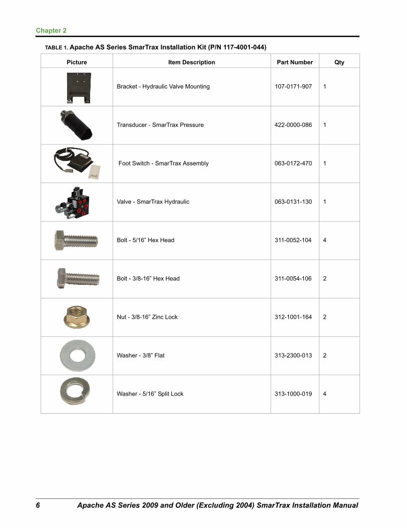
TABLE 1. Apache AS Series SmarTrax Installation Kit (P/N 117-4001-044)
Picture Item Description Part Number Qty
Not pictured Manual - SmarTrax Installation 016-4001-044 1
Not pictured Manual - SmarTrax Operation 016-0171-277 1
Cable - SmarTrax Deutsch Node 115-4001-045 1
Cable - SmarTrax Valve Harness 115-4001-046 1
Cable - Power 115-4001-077 1
Cable - CAN BUS 6” Adapter Tee 115-017-364 1
ORFS Fitting (M)SAE O-Ring Fitting (M)JIC Fitting (M)
Chapter 2
6 Apache AS Series 2009 and Older (Excluding 2004) SmarTrax Installation Manual
Bracket - Hydraulic Valve Mounting 107-0171-907 1
Transducer - SmarTrax Pressure 422-0000-086 1
Foot Switch - SmarTrax Assembly 063-0172-470 1
Valve - SmarTrax Hydraulic 063-0131-130 1
Bolt - 5/16” Hex Head 311-0052-104 4
Bolt - 3/8-16” Hex Head 311-0054-106 2
Nut - 3/8-16” Zinc Lock 312-1001-164 2
Washer - 3/8” Flat 313-2300-013 2
Washer - 5/16” Split Lock 313-1000-019 4
TABLE 1. Apache AS Series SmarTrax Installation Kit (P/N 117-4001-044)
Picture Item Description Part Number Qty

2
Manual No. 016-4001-044 7
Introduction
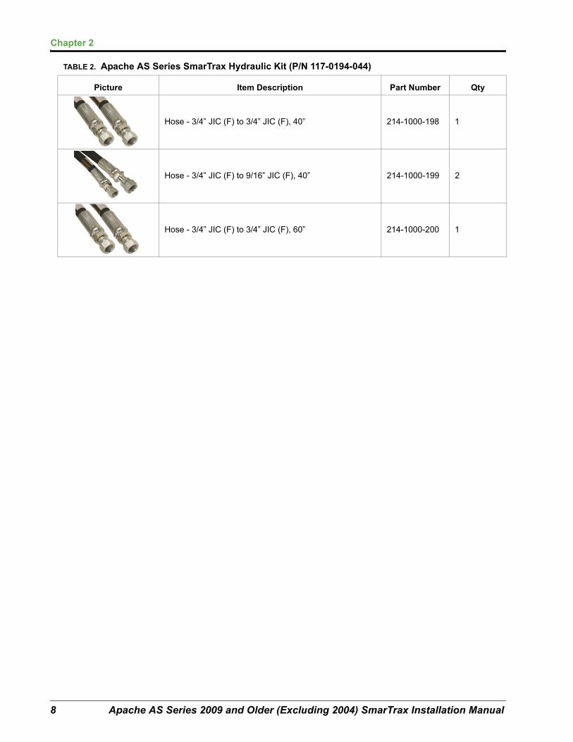
TABLE 2. Apache AS Series SmarTrax Hydraulic Kit (P/N 117-0194-044)
Picture Item Description Part Number Qty
Fitting - 9/16” JIC (M/F) 45° Swivel Elbow 333-0012-027 3
Fitting - 3/4” JIC (M/M/F) Swivel Run Tee Adapter 333-0012-039 1
Fitting - 9/16” JIC (M/F) 90° Swivel Elbow 333-0012-042 4
Fitting - 9/16” JIC (M/M/F) Swivel Run Tee Adapter 333-0012-043 2
Fitting - 9/16” JIC (M) to 9/16” SAE O-RING (M) Straight Adapter
333-0012-045 2
Fitting - 3/4” JIC (M) to 7/8” SAE O-RING (M) Straight Adapter
333-0012-056 2
Fitting - 3/4” JIC (M/F) 90° Swivel Elbow 333-0012-064 4
Fitting - 9/16” JIC (M) to 7/8” SAE O-RING (M) Straight Adapter
333-0012-106 1
Fitting - 3/4” JIC (M) to 3/4” JIC (M) Straight Adapter 333-0012-164 2
Hose - 9/16” JIC (F) to 9/16” JIC (F), 108” 214-1000-197 2
Chapter 2
8 Apache AS Series 2009 and Older (Excluding 2004) SmarTrax Installation Manual
Hose - 3/4” JIC (F) to 3/4” JIC (F), 40” 214-1000-198 1
Hose - 3/4” JIC (F) to 9/16” JIC (F), 40” 214-1000-199 2
Hose - 3/4” JIC (F) to 3/4” JIC (F), 60” 214-1000-200 1
TABLE 2. Apache AS Series SmarTrax Hydraulic Kit (P/N 117-0194-044)
Picture Item Description Part Number Qty

CHAPTER
3
Manual No. 016-4001-044 9
Chapter 3Mounting the SmarTrax Hydraulic Valve
Mount the SmarTrax Hydraulic Valve
Install Fittings on the SmarTrax ValveBefore mounting the SmarTrax valve on the machine, install the proper fittings in the valve. This prepares the valve for installation and simplifies the hose connection process later in the procedure. Refer to the following table to install the fittings in the appropriate ports of the SmarTrax valve.
Install Pressure Transducer
Install the pressure transducer directly to the ‘PS’ Port on the SmarTrax hydraulic valve.
FIGURE 1. Pressure Transducer Connected to SmarTrax Hydraulic Valve
Fitting Part Number Port
9/16” JIC (M) to 9/16” SAE O-RING (M) Straight Adapter 333-0012-045 A and B
3/4” JIC (M) to 7/8” SAE O-RING (M) Straight Adapter 333-0012-056 P and EF
9/16” JIC (M) to 7/8” SAE O-RING (M) Straight Adapter 333-0012-106 T
Pressure Transducer

Chapter 3
10 Apache AS Series 2009 and Older (Excluding 2004) SmarTrax Installation Manual
Mount the SmarTrax Hydraulic Valve1. Mount the SmarTrax hydraulic valve (P/N 063-0131-130) to the mounting bracket (P/N 107-0171-907)
using the supplied 5/16” bolts (P/N 311-0052-104) and 5/16” lock washers (P/N 313-1000-019).
2. Mount the mounting bracket to the bottom of the catwalk behind the fuel tank and fill station controls using the supplied 3/8” bolts (P/N 311-0054-106), 3/8” flat washers (P/N 313-2300-013), and 3/8” lock nuts (P/N 312-1001-164).
FIGURE 2. Valve Mounting Location
SmarTrax Valve (P/N 063-0131-130)
SmarTrax Mounting Bracket (P/N 107-0171-907)
Valve Mounting Location

CHAPTER
4
Manual No. 016-4001-044 11
Chapter 4Hydraulic Connections
WARNINGHydraulics may be under pressure. Never attempt to open or work on a hydraulic system with the equipment running. Care should always be taken when working on a system that has previously been pressurized. When disconnecting or purging hydraulic connections, be aware that hydraulic oil within the system may be extremely hot and under high pressure.
WARNINGTampering with hydraulic valves may cause serious injuries or death and will void warranty.
CAUTIONEnsure precautions are taken to prevent any foreign material or contaminants from being introduced into the machine’s hydraulic system. Objects or materials that are able to bypass the machine’s hydraulic filtration system will adversely reduce performance and possibly damage the SmarTrax hydraulic valves.
CAUTIONBefore beginning the SmarTrax hydraulic installation procedure, turn off the machine and relieve hydraulic pressure by turning the wheel left and right.

Chapter 4
12 Apache AS Series 2009 and Older (Excluding 2004) SmarTrax Installation Manual
Install the Pressure and the Excess Flow Hoses
AS Models1. Locate the steering pump on the back of the transmission below the cab.
For 2006 and older models- Disconnect the existing pressure hose from the pump. Install the supplied 3/4” JIC (M/M) connector fitting (P/N 333-0012-164) to the pressure hose and connect the supplied 3/4” JIC (F) hose (P/N 314-100-200) to the other end of the fitting.
For 2007 and newer models- Remove the hose from the filter and attach the supplied 3/4” JIC (F) hose (P/N 214-1000-200) to the filter.
FIGURE 1. Pressure Connection
2. Route the hose to Port ‘EF’ on the SmarTrax hydraulic valve using a 3/4” JIC 90° elbow (P/N 333-0012-064) if necessary.
3. Connect the supplied 3/4” JIC (F) hose (P/N 214-1000-198) to the Port ‘P’ on the SmarTrax hydraulic valve.
4. Route the other end of the hose to the open port on the steering pump.
FIGURE 2. SmarTrax Hydraulic Valve
‘P’ Port
‘EF’ Port

4
Manual No. 016-4001-044 13
Hydraulic Connections
710 Models1. Disconnect the existing pressure hose from the steering pump.
2. Route the hose to Port ‘EF’ on the SmarTrax hydraulic valve using a 3/4” JIC 90° elbow (P/N 333-0012-064) if necessary.
FIGURE 3. Pressure Connection
3. If needed, connect the supplied hoses (P/N 214-1000-198 and 200) together using the supplied 3/4” JIC (M/M) connector fitting (P/N 333- 0012-164).
4. Attach one end to the pressure port on the pump and the other end to the Port ‘P’ on the SmarTrax hydraulic valve.
FIGURE 4. SmarTrax Hydraulic Valve
‘P’ Port
‘EF’ Port

Chapter 4
14 Apache AS Series 2009 and Older (Excluding 2004) SmarTrax Installation Manual
Install the Tank Hose (All Models)1. Disconnect the existing tank hose from the ‘GPS’ port on the valve block under the cab.
2. Install the 3/4” JIC (M/M/F) supplied run tee (P/N 333-0012-039) and reconnect the original tank hose to the fitting.
FIGURE 5. Tank Connection
3. Connect the 3/4” JIC (F) end of the supplied hose (P/N 214-1000-199) to the remaining branch of the tee fitting and route the 9/16” JIC (F) end of the hose to Port ‘T’ of the SmarTrax hydraulic valve.
FIGURE 6. SmarTrax Hydraulic Valve
Port ‘T’
4
Manual No. 016-4001-044 15
Hydraulic Connections
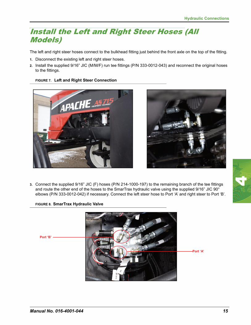
Install the Left and Right Steer Hoses (All Models)The left and right steer hoses connect to the bulkhead fitting just behind the front axle on the top of the fitting.
1. Disconnect the existing left and right steer hoses.
2. Install the supplied 9/16” JIC (M/M/F) run tee fittings (P/N 333-0012-043) and reconnect the original hoses to the fittings.
FIGURE 7. Left and Right Steer Connection
3. Connect the supplied 9/16” JIC (F) hoses (P/N 214-1000-197) to the remaining branch of the tee fittings and route the other end of the hoses to the SmarTrax hydraulic valve using the supplied 9/16” JIC 90° elbows (P/N 333-0012-042) if necessary. Connect the left steer hose to Port ‘A’ and right steer to Port ‘B’.
FIGURE 8. SmarTrax Hydraulic Valve
Port ‘A’
Port ‘B’

Chapter 4
16 Apache AS Series 2009 and Older (Excluding 2004) SmarTrax Installation Manual
Hydraulic Connection Diagram

CHAPTER
5
Manual No. 016-4001-044 17
Chapter 5Wiring and Electrical Connections
Connecting the SmarTrax Hydraulic Valve1. Locate the connector labeled ‘LEFT’ on the SmarTrax valve cable harness (P/N 115-4001-046).
2. Insert the connector labeled ‘LEFT’ to the bottom solenoid installed in port ‘2’ on the SmarTrax hydraulic valve. See Figure 5, “Cable Harness Installation Schematic,” on page 21.
3. Repeat step 1 and step 2 to connect the ‘RIGHT’ connector to the top solenoid on port ‘2’.
4. Locate the connector labeled ‘Double Blocker 1 and 2’ on the SmarTrax valve cable harness. Insert the connectors into the ‘1A and 1B’ solenoids.
Connecting the Pressure Transducer1. On the valve cable harness (P/N 115-4001-046), identify the connector labeled ‘PSI’.
2. Connect the ‘PSI’ connector to the pressure transducer using the provided di-electric if necessary.
CAUTIONEnsure that the power cable is the last cable connected.Do not reverse the power leads. Doing so will cause severe damage to the equipment. Ensure the leads are connected to the correct polarity.
Chapter 5
18 Apache AS Series 2009 and Older (Excluding 2004) SmarTrax Installation Manual
Route the Valve Cable HarnessOnce the SmarTrax hydraulic valve and pressure transducer are connected to the valve cable harness, route the remaining connectors into the cab.
1. Locate an access point through which the valve cable harness (P/N 115-4001-046) may be routed into the cab.
2. Route the cable to the access point and use the provided cable ties to secure the cable to avoid catching or damaging the cable during normal equipment operation.
Note: When routing the SmarTrax valve cable harness, follow the path of other hoses or cables to avoid potential wear areas.
3. Feed enough of the cable into the cab to allow each cab control component to be connected.
4. Spool and secure any excess cable.
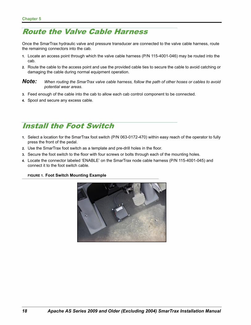
Install the Foot Switch1. Select a location for the SmarTrax foot switch (P/N 063-0172-470) within easy reach of the operator to fully
press the front of the pedal.
2. Use the SmarTrax foot switch as a template and pre-drill holes in the floor.
3. Secure the foot switch to the floor with four screws or bolts through each of the mounting holes.
4. Locate the connector labeled ‘ENABLE’ on the SmarTrax node cable harness (P/N 115-4001-045) and connect it to the foot switch cable.
FIGURE 1. Foot Switch Mounting Example

5
Manual No. 016-4001-044 19
Wiring and Electrical Connections
Install the SmarTrax NodeWhen choosing the location for the SmarTrax node, consider the following points:
• The node is not weatherproof. Mount the SmarTrax node inside the machine’s cab or driver’s compartment.
• The node mounting location must not create tripping hazards and allow cable routing to avoid crimping or damaging the cables or the node connections.
• Mount the SmarTrax node to a flat surface with two of the arrows on the node parallel to the ground and in a location where it will not be kicked or jarred during normal equipment operation.
• One of the six numbered direction arrows on the node must be oriented in the direction of forward vehicle travel. Note the number of the arrow corresponding to forward travel for SmarTrax calibration. One arrow must also point straight up.
• Mount the node to a flat, level surface.
• Securely fasten the node using bolts or screws through at least two of the three mounting holes. When mounted properly, the node should not become loose or rotate.
FIGURE 2. Node Mounting
Direction Arrows
Any two arrows must be parallel with level ground
Mounting Tabs

Chapter 5
20 Apache AS Series 2009 and Older (Excluding 2004) SmarTrax Installation Manual
To Install the Node:1. Remove the side panel on the machine.
2. Next, remove the three bolts from the fuse mount.
FIGURE 3. Side Panel
3. Using the mounting tabs on the node as a template, mark and pre-drill holes. Using bolts or self tapping screws (not supplied), secure the node into position.
FIGURE 4. Node Installed
4. Connect the rectangular 12 pin connectors on the node cable (P/N 115-4001-045) for Viper Pro/Envizio Pro to the SmarTrax valve cable harness (P/N 115-4001-046).
5. Connect the large, rectangular connectors to the SmarTrax node.
6. Connect your receiver or source of DGPS to the connector labeled ‘DGPS’ on the node adapter cable.
7. Connect the console providing machine guidance to the remaining DB-9 connector.
8. Connect the 4-pin deutsch plug to the vehicle’s CANbus system (Viper Pro/Envizio Pro) or the DB-9 display cable (Cruizer).
9. Electrical hookup is recommended as shown in the Can Node Wiring Diagram on page 26.
10. Use power cable (P/N 115-4001-077) to connect to power. For 2009 model year, an optional power cable (P/N 700-000-533) is available from the factory/Apache Dealer.
Note: High Current Power, which is used to run steering operations, should be connected to a separate power source than Logic Power, which is used to run processing and communication between the node and the guidance console.
Remove

5
Manual No. 016-4001-044 21
Wiring and Electrical Connections
FIGURE 5. Cable Harness Installation Schematic

Chapter 5
22 Apache AS Series 2009 and Older (Excluding 2004) SmarTrax Installation Manual

CHAPTER
6
Manual No. 016-4001-044 23
Chapter 6Start-Up Procedures
Remove Air from the Hydraulic SystemAnytime a hydraulic system is purged for maintenance, or during the SmarTrax system installation, air is introduced into the hydraulic lines. Anytime the system is purged or fittings are loosened or disconnected, it is important to remove air pockets from the hydraulic system to avoid unwanted operation of the hydraulic system.
To remove air from the hydraulic system, turn the wheels fully from side to side repeatedly. If air pockets are present, the wheels may not move consistently while the steering wheel is operated. Continue turning the wheels until the wheels move steadily and smoothly with the steering wheel.
WARNINGWhen starting the machine for the first time, keep the area around the machine clear of people or bystanders in case a fitting or hose has not been fully tightened.
WARNINGDO NOT use hands to check for leaks. Hydraulic fluid under pressure can penetrate the skin and cause serious injury or death.
Always wear appropriate protective equipment when working with the hydraulic system.

Chapter 6
24 Apache AS Series 2009 and Older (Excluding 2004) SmarTrax Installation Manual
Verify the SmarTrax Installation1. Turn on the machine.
2. With the machine running, double-check all fitting and hose connections to ensure that:
• Hoses are not rubbing or interfering with other moving parts.
• Hydraulic fluid is not leaking.
3. If there are any problems, shutdown the machine and correct problems immediately.
If you need additional assistance, contact your local Raven dealer or the Raven Customer Support Center at1-800-243-5435.

CHAPTER
7
Manual No. 016-4001-044 25
Chapter 7System Drawings
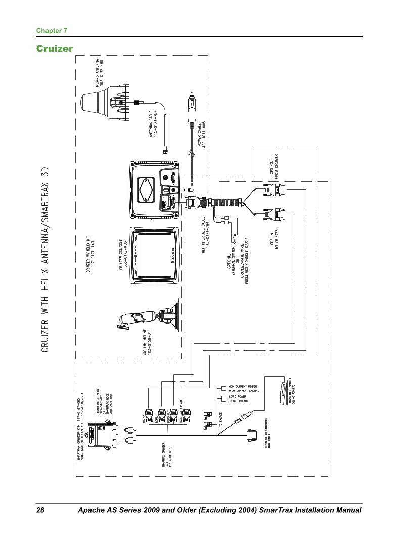
The following diagrams may be helpful for installing or troubleshooting the SmarTrax system. The following diagrams may show optional features or components not required for operation and will not apply to your system if the required hardware has not been installed.
Contact your local dealer for purchasing or more information on components shown in the following diagrams.
Additional system diagrams are available from the Raven Industries web site:
http://www.ravenprecision.com/Support/ApplicationDrawings/index2.jsp

Chapter 7
26 Apache AS Series 2009 and Older (Excluding 2004) SmarTrax Installation Manual
Can Node Wiring Diagram

7
Manual No. 016-4001-044 27
System Drawings
Envizio Pro/ Viper Pro
Chapter 7
28 Apache AS Series 2009 and Older (Excluding 2004) SmarTrax Installation Manual
Cruizer

Index
Manual No. 016-4001-044 29
Numerics710 Models Pressure and Excess Flow
Hoses- Installation 13
AAS Models Pressure and Excess Flow
Hoses- Installation 12
CCAN Node Wiring Diagram 20Console Cable Harness Routing 18
EExcess Flow Hose- Installation 12
HHydraulic Connection Diagram 16Hydraulic Connections 11
IInstallation
Foot Switch 18Recommendations
SmarTrax Node 19
KKit Contents 5
LLeft Steer Hose- Installation 15
MMount the SmarTrax Hydraulic Valve 9
PPreparing for Installation 4
Point of Reference 4Recommendations 4Tools Needed 4
Pressure Hose- Installation 12
RRight Steer Hose- Installation 15
SSafety Information 1
Electrical Safety 2Hydraulic Safety 2
Start-Up ProceduresVerify the SmarTrax Installation 24
System Drawings 25
TTank Hose- Installation 14
UUpdates 4
WWiring & Electrical Connections
Pressure Transducer 17SmarTrax Hydraulic Valve 17
Wiring and Electrical Connections 17

Index
30 Apache AS Series 2009 and Older (Excluding 2004) SmarTrax Installation Manual

Raven Industries will not assume any expense or liability for repairs made outside our facilities without written consent. Raven Industries is not responsible for damage to any associated equipment or products and will not be liable for loss of profit or other special damages. The obligation of this warranty is in lieu of all other warranties, expressed or implied, and no person or organization is
authorized to assume any liability for Raven Industries.
Damages caused by normal wear and tear, misuse, abuse, neglect, accident, or improper installation and maintenance are not covered
by this warranty.
What Does this Warranty Cover?
How Long is the Coverage Period?
How Can I Get Service?
What Will Raven Industries Do?
What is not Covered by this Warranty?
Bring the defective part and proof of purchase to your Raven dealer.If your dealer agrees with the warranty claim, the dealer will send the part and proof of purchase to their distributor or to Raven Industries
for final approval.
Upon confirmation of the warranty claim, Raven Industries will, at our discretion, repair or replace the defective part and pay for return
freight.
RAVEN INDUSTRIESLimited Warranty
This warranty covers all defects in workmanship or materials in your Raven Applied Technology Division product under normal use,
maintenance, and service.
Raven Applied Technology Division products are covered by this warranty for 12 months after the date of purchase. This warranty coverage applies only to the original owner and is nontransferable.