ap800 - aunexusa.com
TRANSCRIPT
AP Series 1 Channel Amplifiers
Performance Class D Mono Amplifier Series
Models: AP800.1D, AP1200.1D
Installation and Operation Manual
Please take time to thoroughly read through this manual to familiarize yourself with your new amplifier. This will ensure that your amplifier will perform at its optimum capabilities.
Para obtener una copia de este manual en español, visite www.aunexusa.com y luego vaya a la página del producto que necesita. Haga clic en la pestaña Soporte y descargue su manual en español.
AP1200.1D
AP800.1D
1
Congratulations and thank you for purchasing an Aunex AP Series Amplifier. This product has been engineered and manufacturedutilizing precision quality parts and craftsmanship. Improvements in sound quality and system performance will be greatly enhanced with the use of this amplifier.
To ensure maximum performance we highly recommend you have your new Aunex product installed by an Authorized Aunex Dealer. Should you decide to install this product yourself, please make sure to read this manual thoroughly to familiarize yourself with the necessary installation requirements and tuning procedures.
Please read your warranty and retain a copy of your purchasereceipt and original carton should your amplifier ever needsto be serviced and warranted.
Visit our website for the latest information on all Aunex products at: www.aunexusa.com. If you have any questions regarding this product, please contact your Authorized Aunex Dealer forassistance or call / email Aunex Technical Support Department at (909) 589-5010 / [email protected].
Caution: Continuous exposure to sound pressure levels over 100dBmay cause permanent hearing loss. High powered audio systems canproduce sound pressure levels that can exceed over 150dB. Please limit your exposure to continuous high listening volumes.

2
Feature Set of the AP Series Mono Amplifiers
• Heavy Density Aluminum Extruded Heatsink• 2 Layer PCB, SMD Technology• Differential Balanced RCA Inputs• Fully Variable Crossover 30Hz – 500Hz @ 24dB/Octave Slope• Fully Variable Infrasonic Filter 10Hz – 50Hz @ 24dB/Octave• Boost Eq. 0 – 18dB @ 45Hz Center• Fully Variable Phase 0 - 180⁰ • Auto-sensing in High Level Input Mode o Remote Input Becomes Remote Output Trigger if High level Input is used. • Power and Protection Logo Illuminated Status Indicator o Blue Indicates Amplifier is powered On o Red Indicates the Amplifier is in Protection • 4 Gauge Power & Ground Terminals• 12 Gauge Speaker Output Terminals• Advance Protection Circuit Monitoring: Short, Thermal, Overload and Impedance• Finish: Anodized with Texture Paint
What’s Included
• (1) AP Series Mono Class D Amplifier • (1) Remote Level Controller and Cable• (1) High Level Speaker Plug• (6) Self Tapping Screws; (4) for Amplifier, (2) for Remote• (2) Allen Wrenches• (1) Instruction Manual• (1) Sticker

3
Important Safety Considerations
• To prevent personal injury and damage to the unit, please read the following instructions in this manual. • This product is designed to use in vehicles with 12Volt, negative-ground electrical systems. • Install this product in a dry location away from your vehicles’ safety equipment (airbags, seat belt system, etc.). Water and humidity may damage internal components. • Use the included mounting accessories to secure this product so that it does not come loose. • Check before drilling to make sure you do not drill into any vital vehicle system. • Protect all system wiring from sharp metal edges. • Do not disassemble or modify this unit; doing so will void your manufacturer’s warranty.
Important Installation Precautions
Installation of mobile audio equipment requires experience.Although this manual provides general installation procedures,it will not show the exact installation method for your particularvehicle.
If you do not have the required knowledge and experience,we recommend that you have your equipment installed by anAuthorized Aunex Dealer.
• Turn off all stereo and other electrical devices before you begin.• Disconnect the negative (-) lead from your vehicle’s battery to avoid an electrical short. Reconnect the negative lead to your battery once your installation is complete. So, in other words the negative lead from our vehicle’s battery is the first connection you remove before starting your installation and the last connect your make after you finish your installation. • Check your mounting location to make sure there is sufficient room for your installation placement preference.

4
Mounting Placement
Choose a structurally sound location to mount your Aunexamplifier, making sure there are no items behind the area wherethe screws will be driven.
For optimum sound quality, it is highly recommended that youpurchase Aunex wiring accessories as they are designed to give your amplifiers high-quality signal it needs to operate at peakperformance levels. Aunex provides a wide selection from RCA cables and power wire to speaker wire and battery connectors.
Important Installation Precautions Continued
• Install this product in a dry location away from your vehicles’ safety equipment. Keeping the amplifier dry and installed in a well-ventilated area will help ensure many years of listening enjoyment.• When running power cables through sheet metal it is best to use grommets and loom to properly insulate your cables from metal edges. • Avoid mounting the amplifier with the top fins facing down as this may increase the operating temperature of your amplifier.• If mounting underneath a seat, make sure that there is at least 1 inch (25mm) of space above the amplifier to permit proper cooling. • Avoid mounting the amplifiers on a subwoofer enclosure as prolonged excessive vibration may damage your amplifier.

5
Side Panel Layout
1 2
9 10 11 12 13
3 4 5 6 7 8
1. Remote Level Control: With the Remote Level Control plugged to your amplifier, you can now adjust the amount of output of your subwoofer from the convenience of this controller.
6
Side Panel Layout Continued
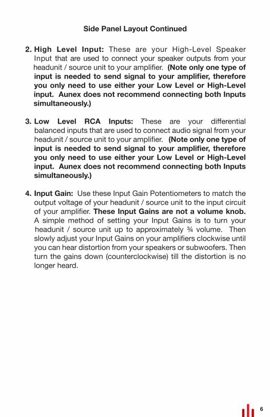
2. High Level Input: These are your High-Level Speaker Input that are used to connect your speaker outputs from your
headunit / source unit to your amplifier. (Note only one type of input is needed to send signal to your amplifier, therefore you only need to use either your Low Level or High-Level
input. Aunex does not recommend connecting both Inputs simultaneously.)
3. Low Level RCA Inputs: These are your differential balanced inputs that are used to connect audio signal from your headunit / source unit to your amplifier. (Note only one type of input is needed to send signal to your amplifier, therefore
you only need to use either your Low Level or High-Level input. Aunex does not recommend connecting both Inputs simultaneously.)
4. Input Gain: Use these Input Gain Potentiometers to match the output voltage of your headunit / source unit to the input circuit of your amplifier. These Input Gains are not a volume knob. A simple method of setting your Input Gains is to turn your
headunit / source unit up to approximately ¾ volume. Then slowly adjust your Input Gains on your amplifiers clockwise until you can hear distortion from your speakers or subwoofers. Then turn the gains down (counterclockwise) till the distortion is no longer heard.

7
Side Panel Layout Continued
5. Infrasonic Filter: This variable potentiometer will provide a roll off point for lower frequencies (10Hz – 50Hz variable) that could potentially damage your subwoofers from over-excursion. The frequency setting for your Infrasonic Filter is to be set relative to your speaker’s low-frequency capabilities along with enclosure tuning. In a sealed box Aunex recommends setting the
Infrasonic Filter between 25Hz – 35Hz. In a ported enclosure Aunex recommends setting the Infrasonic filter at ½ an Octave below your tuned frequency.
For example, let say your ported enclosure is tuned at 40Hz. Take ½ of 40Hz which is 20Hz (this is one octave lower). Now take another half off 20Hz which is then 10Hz (this is half anoctave lower). Now take 10Hz from 40Hz which is 30Hz and where you should set your Infrasonic Filter.
6. Boost Eq: Your AP Series amplifiers incorporates a Boost Eq. circuit that can increase output 0-18dB centered at 45Hz. Note if you turn up the Boost Eq, you will need to readjust the Input Gains to avoid clipping the output signal.
7. Phase Switch: Depending on the absolute phase of your main speakers and amplifier and the distances of the subwoofer and the main speaker from the main listening position, the bass in the crossover region maybe smoother if you reverse the
subwoofer’s phase. Try both settings to determine which polarity produces the best overall bass performance in your system. Typically, though, phase is left at the 0⁰ for most installation.
8. Low Pass (LP) Filter Frequency Filter: This potentiometer allows you to adjust the crossover frequency from 30Hz – 500Hz.

8
9. Speaker Outputs: Your AC amplifier speaker outputs are designed to accept 16 AWG to 12 AWG wire. Turn the set screws
on this terminal counterclockwise to loosen the screws using the supplied Hex wrench. Strip the PVC jacket from your speaker wire ½ inch (12mm). Then insert the bare wire into the terminal block so that no bare speaker wire is exposed. Then tighten the set screw by turning it clockwise.
Loading your amplifier below the recommendedimpedance rating found on page 14 is not recommended and may cause your amplifier to enter into protection mode and may void your warranty.
For maximum current flow, Aunex recommends that you tin your speaker wire before connecting it to the speaker outputterminals. In addition, Aunex recommends using highquality 100% OFC (Oxygen Free Copper) or Tinned 100% OFCspeaker wire. This will ensure that your speaker / subwoofer receives maximum output from your amplifier.
10. Fuse Holder: This is your fuse block. Should there be a short in your system or if your amplifier is being overdriven, these fuse(s) will typically burn to prevent damage to your amplifier. If it is required to replace your fuse(s), use the same fuse rating that comes with your amplifier. Using a higher fuse may damage your amplifier and will void your warranty.
11. +12Volt Positive Terminal: The +12Volt positive terminal is designed to accept up to 4 AWG wire. Use the supplied fuse block and make your +12Volt connection directly to the positive battery post. The Fuse should be installed within 18” (457mm) of the battery. This fuse is vital to protecting the vehicle and amplifier from a dead short. Turn the set screws on this terminal counterclockwise to loosen the screw using the supplied Hex wrench. Strip the PVC jacket from your power wire ½ inch (12mm). Then insert the bare wire into the terminal block so that no bare power wire is exposed. Then tighten the set screw by turning it clockwise.
Side Panel Layout Continued

9
For maximum current flow, Aunex recommends that you tin your power wire before connecting it to the +12Volt terminal. Inaddition, Aunex recommends using high quality 100% OFC (Oxygen Free Copper) or Tinned 100% OFC speaker wire. This will ensure that your speaker / subwoofer receives maximum output from your amplifier.
12. Remote Input Terminal: This terminal must be connected to a switched +12Volt source. If the source unit does not have a remote Turn on lead, then a switched +12 supply should be used such as the ACC +12Volt. Run an 18-gauge wire from the Remote Turn-On Lead from your headunit / source unit to this terminal.
If you are using the High-Level Speaker Outputs connection to the amplifiers’ RCA inputs, you do not need to connect a remote input to your amplifier. Your amplifier willautomatically detect the speaker signal and will turn on your amplifier via its DC Offset circuit. In addition, theremote input terminal then becomes a remote output trigger which can be used to turn on another amplifier or processor that requires a +12volt remote connection.
13. Ground: The ground terminal is designed to accept up to 4 AWG wire. Make your ground connection directly to the chassis of the vehicle as close to the amplifier as possible. Make sure this connection is made with the same gauge wire as used for your +12Volt connection. Ensure that all dirt, grease and paint is removed from your chassis ground point prior to attaching the ground wire. Aunex recommends when making your chassis ground to use a star washer which will help prevent your ground bolt from loosening.
Side Panel Layout Continued

10
Power Connection
For maximum current flow, Aunex recommends that you tin your ground wire before connecting it to the ground terminal of your amplifier. In addition, Aunex recommends using high quality 100% OFC (Oxygen Free Copper) or Tinned 100% OFC speaker wire. This will ensure that your speaker / subwoofer receives maximum output from your amplifier.
Connect to Source unit’saccessory lead orswitched 12v source
Connect to chassis groundof vehicle. Keep Grounds as shortas possible
See Specifications for Fuse Rating
Fuse
Less than 18”
Vehicle Battery
_NEG
+POS

11
Common Installation Diagrams
The illustrations below show the common installation methods for your amplifier. It is important to make sure that the impedance of your subwoofers is either 1 ohm or higher. Connecting youramplifier below these impedances are not recommended as they will cause your amplifier to go into protection. If you are unsure of the impedance, it is recommended that use a DMM (Digital Multi-Meter) to check the impedance of your connection at theamplifiers’ Speaker Output Terminals. Your amplifier will need to be off in order to get accurate measurements.
1. A Single Voice Coil Subwoofer Speaker
1-OHM Subwoofer
(min)+ _
12
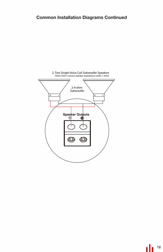
Common Installation Diagrams Continued
2-4 ohm Subwoofer
2. Two Single Voice Coil Subwoofer Speakers (Note: Don’t connect speaker impediance under 1 ohm)
+ _ + _

13
Note: One of the leading causes of amplifierfailure is using inferior Power, Ground andSpeaker wires that are not sufficient inquality to deliver the necessary current to keep youramplifier performing at its peak level. As all Aunex amplifiers are designed to deliver high power output, we recommend that you do not use any power wires that contains CCA(Copper Clad Aluminum). Instead we recommend only using high quality 100% OFC (Oxygen FreeCopper) or 100% Tinned OFC (Oxygen FreeCopper) wires. This will help give youramplifier the proper current and will ensure that your amplifier will perform at this peakperform level for many years to come.
Ask your Authorized Aunex Dealer or visitwww.aunexusa.com to view the complete line ofinstallation accessory that will compliment your audio investment. Aunex provides a wide election from RCA cables and power wire to speaker wire and battery connectors.

14
Technical Specifications
*Due to continuous product improvements; specifications and features are subject to change without notice. Please visit www.aunexusa.com for the most current information.
*This manual is the exclusive property of Aunex, Inc. Any reproduction of this manual or use other than its intended purposes is strictly prohibited without the express written consent of Aunex, Inc. ©Copyright 2020 Aunex, Inc.
Specifications AP800.1D AP1200.1DChannels 1 1Rated RMS Power 4 Ohms Mono @ 14.4 Volts 300 Watts x 1 500 Watts x 1Rated RMS Power 2 Ohms Mono @ 14.4 Volts 600 Watts x 1 900 Watts x 1Rated RMS Power 1 Ohm Mono @ 14.4 Volts 800 Watts x 1 1200 Watts x 1Peak Music Power 1600 Watts 2400 WattsFrequency Response 10Hz – 500Hz 10Hz – 500HzTHD + Noise < 0.5% < 0.2%S/N Ratio A-Weighted > 105dB > 106dBInput Sensitivity (Low Level RCA) 250mV – 6V 250mV – 6VInput Sensitivity (High Level Speaker Output) 450mV – 11V 450mV – 11VCrossover Low Pass (24dB/Octave) 50Hz – 500Hz 50Hz – 500HzBoost EQ Low Pass - 45Hz Centered 0 – 18dB 0 – 18dB Infrasonic Filter 10Hz – 50Hz 10Hz - 50HzPhase - Fully Variable 0 - 180⁰ 0 - 180⁰Efficiency @ 4 Ohm 85% 85%Operating Voltage 9 – 17 Volts 9 – 17 VoltsFuse Requirement 80A (Included) 120A (Included)Dimensions (H x W x D) Inches 2.0 x 8.5 x 7.2 2.0 x 11.6 x 7.2 Dimensions (H x W x D) MM 52 x 215 x 182 52 x 295 x 182

15
TroubleshootingProblem Solution
1. Check to see if Power, Remote and Ground is connected to the Amplifier.2. Check Power and Remote Turn-on lead for proper +12 Voltage. (12 - 16 Volts DC acceptable range.)3. Check the inline fuse, replace if necessary.1. Check your RCA connectors to see if there is signal with a DMM (Digital Multi-Meter) to measure AC voltage.2. Check your speakers to see if there is short. 1. Readjust your amplifiers gains to lower setting.2. Readjust your source unit volume.3. Make sure your RCA's and Speaker wires are routed away from your Power and Ground connections.4. Remove existing ground wires for all electrical components. Reground wires to a different location. Verify the grounding location is clean, paint from ground point has been removed and is rust free.5. Add a secondary ground cable from the negative battery terminal to the chassis metal or engine block of vehicle.6. Check your RCA cables or speaker input for any damage.1. Readjust your amplifiers gains to a lower setting.2. Readjust your source unit volume.3. Readjust the Boost Eq. 1. Amplifier may be in thermal protection due to heat. 2. Check the inline fuse, replace if necessary.3. Check the voltage at the amplifier power input terminals.
Logo Status LED is Red / Protection Circuit Active
Amplifier does not work; no LED's on
Amplifier powers up; no sound
Distorted sound from speakers
Hissing / Enginer noise from speakers

16
California’s Proposition 65 (Prop 65) entitles consumers inCalifornia to special warnings for products that contain chemicals knows to the state of California to cause cancer,birth defects or other reproducttive harm if consumers areexposed to such chemicals above certain threshold levels.
While this law is only for California and Aunex sells products to consumers in California, Aunex is required to display this warning.
California Prop 65 Warning
Warning: This product can expose you to chemicals which are known to the State of California to cause cancer or birth defectsor other reproductive harm. For more information visit www.p65warnings.ca.gov.
17
Limited Warranty – AP Series Amplifiers
Aunex, Inc. warrants this product to be free of defects inmaterials and workmanship for a period of 1 year from the original purchase date. This warranty is non-transferrable and applies only to the original purchaser from an Authorized Aunex Dealer. (AnyFactory Refurbished Amplifier (B-Stock Products)carries a 90 Day warranty period.) Should service be necessarywithin the warranty period, Aunex will at its discretion repair orreplace the defective unit with a new or remanufacturedproduct at no charge. Damage caused by misuse, abuse,accidental damage, product modification, failure to follow instalation instructions, unauthorized repairs will not be coveredunder warranty. This warranty does not cover incidental orconsequential damages and does not cover the cost of having the unitremoved or reinstalled. Cosmetic damages by accident ornormal wear and tear are not covered under warranty.Subsequent damage to a other component will not be covered.
Warranty will be voided if the product’s serial number has been removed or defaced. Any applicable implied warranties arelimited in duration to a period of the express warranty asprovided in this manual beginning with the date of the originalpurchase and no warranties whether express or implied shall apply to this product thereafter. Some states do not allow limitation on impliedwarranties; therefore, these exclusions may not apply to you.This warranty gives you specific legal rights; however, youmay have other rights that vary from state to state.
Warranty

All warranty returns should be sent to Aunex freight prepaidand must be accompanied by proof of purchase; a copy of thepurchase sales receipt. All returns whether sent by the Dealer of purchase or directly from the consumers must have a valid RMA number (Return Merchandise Authorization). Returns without avalid RMA number will be refused. The RMA number must be clearly written on the outside of your return package.Non-defective units will be returned to sender freight collect.Customers are responsible for shipping charges and insurance in sending products back to Aunex. Freight damage on returns is not covered under warranty so be sure to package your return in the original box or packaged securely in another box to preventpossible freight damage. Warranty expiration on items without proof of purchase will be determined from the manufacturing date code.
Products purchased outside of the United States of Americaare covered by that country’s distributor and not by Aunex, Inc. For Service Information in the U.S.A. and to obtain a Return Merchandise Authorization number (RMA) please call Aunex at (909) 589-5010.
Warranty Continued

Declare Your Independence!
Aunex, Inc.13865 Magnolia Avenue, Unit C
Chino, CA 91710T. (909) 589-5010 / F. (909) 589-5011
8:30am – 5:30pm (PST – Pacific Standard Time)www.aunexusa.com