ap physics b ch 22, 23, & 24
DESCRIPTION
15/21 AP Physics B.... or College Physics... read to study!!TRANSCRIPT

1
I Love
Physics!

Chapter 22
Electromagnetic Waves
2

22.2 Production of Electromagnetic Waves
Oscillating charges will produce electromagnetic waves:
3

22.2 Production of Electromagnetic WavesThe electric and magnetic waves are perpendicular to each other, and to the direction of propagation.
4
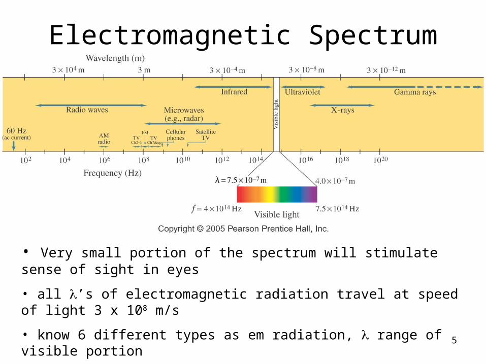
Electromagnetic Spectrum
• Very small portion of the spectrum will stimulate sense of sight in eyes
• all ’s of electromagnetic radiation travel at speed of light 3 x 10⁸ m/s
• know 6 different types as em radiation, range of visible portion
• high frequency gamma rays, X-rays have highest energy
• em radiation does not require a medium to propagate5
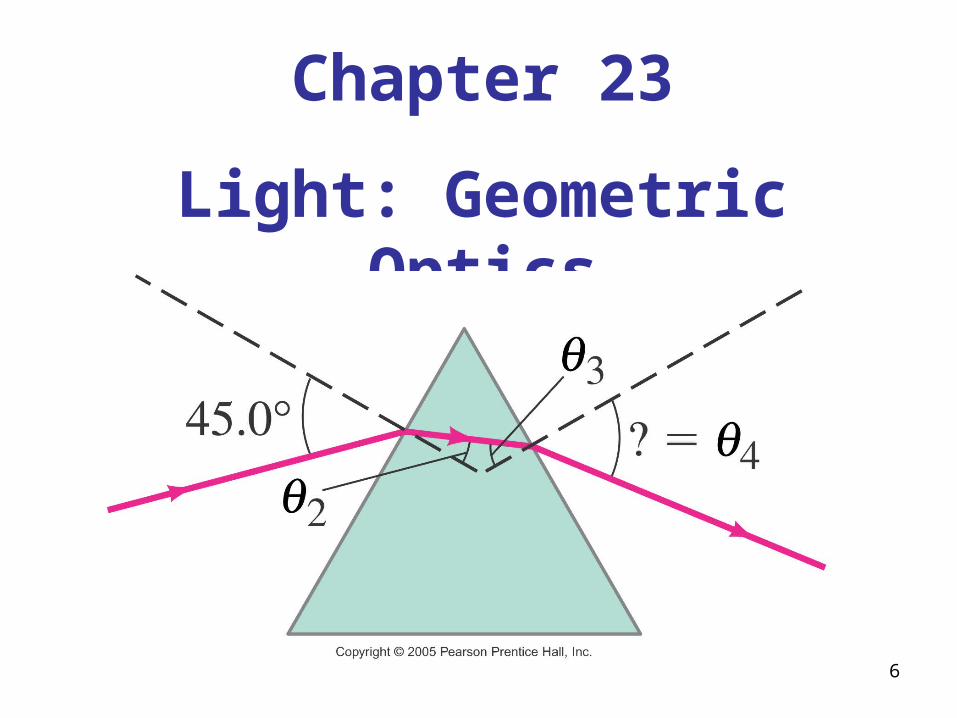
Chapter 23
Light: Geometric Optics
6

Light Rays
Light rays (arrows as in geometry) used to represent the propagating wave fronts they are perpendicular to
7
8
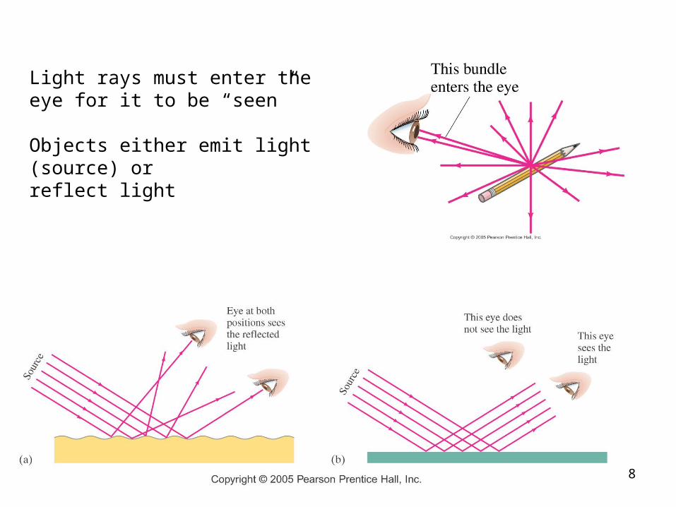
Light rays must enter the eye for it to be “seen”
Objects either emit light (source) orreflect light

Law of Reflection
Law of Reflection:
angle of incidence (i) = angle of reflection (r)
angles of incidence (incoming) and reflection (outgoing) rays are measured FROM THE NORMAL to the reflecting surface NOT from the surface
9

Image Characteristics• “Object” is the real thing in front of the
mirror• Image has 3 characteristics1.Nature
– Real or virtual
2.Orientation– Upright (correct side up) or inverted (upside
down)
3.Size– Larger than the object, same size, smaller
than object10

Image Nature• Real image
– are created in front of the mirror – light rays actually converge at a point– image can appear on a screen – only created by spherical mirrors
• Virtual– appear to be created behind the mirror– no light rays actually converge at or emanate from a
virtual imageI Love
Physics!
11

Plane MirrorsImage characteristics ALWAYS the same:
Nature: Virtual
Orientation: upright
Size: same
Plane mirrors also reverse the image left to right
12

23.2 Reflection; Image Formation by a Plane Mirror
What you see when you look into a plane (flat) mirror is an image, which appears to be behind the mirror.
since reflected rays will not intersect on the real side you must extend the reflected ray to the back side to find virtual image
ho = object height
hi = image height
do = object distance
di = image distance
For plane mirrors
do = di ho = hi 13

Spherical Mirrors
C = center of curvature of the sphere
R = radius of curvature; distance from C to back of mirror
• light ray parallel to principal axis are focussed
• concave – towards the axis
• convex – away from the axis
14

Incident parallel rays
focal point F
15

Concave Convex
parallel incident rays focussed through focal point F in front of mirror
2
Rf
parallel incident rays appear to come from virtual focal point F behind mirror
2
Rf negative focal length
16

Rays 1,2,3 for RTD’s
Opposite of ray 1; through F on way to mirror, out parallel
Through C – back on itself; not always possible
need 2 rays intersecting to locate tip of the object 17

Concave Mirrorsour objects will usually be upright Image
characteristics vary depending on location of object
do
di
ho
hi
18

Virtual Image from Concave Mirror
when object is inside focal point F image becomes virtual, upright, larger
19

Convex Mirrors
• Image characteristics ALWAYS: virtual, upright, smaller• Car mirror on side
20
since reflected rays will not intersect on the real side you must extend the reflected ray to the back side to find virtual image

Mirror Calculations
1 1 1
o id d f Lens-Mirror Equation
i i
o o
h dm
h d Magnification Equation
focal length 2
Rf concave
convex
2
Rf
21

Sign Conventions for Spherical Mirrors (p764)
+ do real object XXXXXX
di real image virtual image
f concave converging
convex diverging
hi upright image inverted image
m upright image inverted image
m > 1.0 larger image m =1.0 same size m < 1.0 smaller image
22

Chapter 26 – Refraction & Lenses
Refraction of light
change in direction of a light ray when it travels from one transparent medium into a different transparent medium of different optical density
23

Refraction • Light ray must be incident on the different
medium at an angle i 0o
• All angles measured from the normal
normal
i
r
medium 1
medium 2
24

Index of Refraction n• Even though light is electromagnetic radiation and does
not require a medium it does change speed when it enters a medium of different optical density
• Index of refraction n is a relative measure of this velocity change
cn
v c = speed of light in vacuum = 3.00 x 10⁸ m/s
v = speed of light in refracting medium
• n is always 1.0 since speed of light in material other than air or vacuum is less than 3 x 10⁸ m/s
• no units for index since it is a coefficient25

26

Direction change due to speed change
slower medium - mud
faster medium - asphalt
wheels of a car driving off road onto shoulder
this wheel moves faster while other wheel moves slower
this explains why light ray must be incident at angle > 0o
27
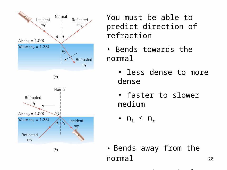
You must be able to predict direction of refraction
• Bends towards the normal
• less dense to more dense
• faster to slower medium
• ni < nr
• Bends away from the normal
• more dense to less dense
• slower to faster medium
• ni > nr28
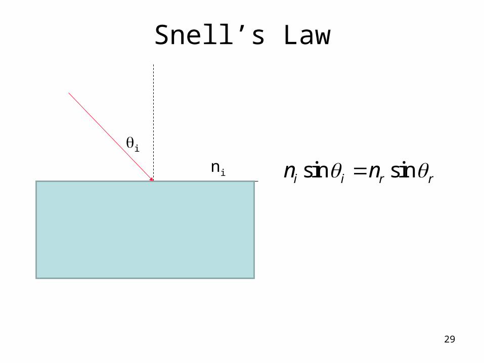
Snell’s Law
ni
nr
i
r
sin sini i r rn n
29

23.6 Total Internal Reflection
When light travels from slower to faster medium there is an angle of incidence for which the angle of refraction will be 90°; this is called the critical angle c:
30

Converging lens
Light rays are refracted twice
• towards normal entering glass
• away from normal exiting glass
31

Diverging lens
32
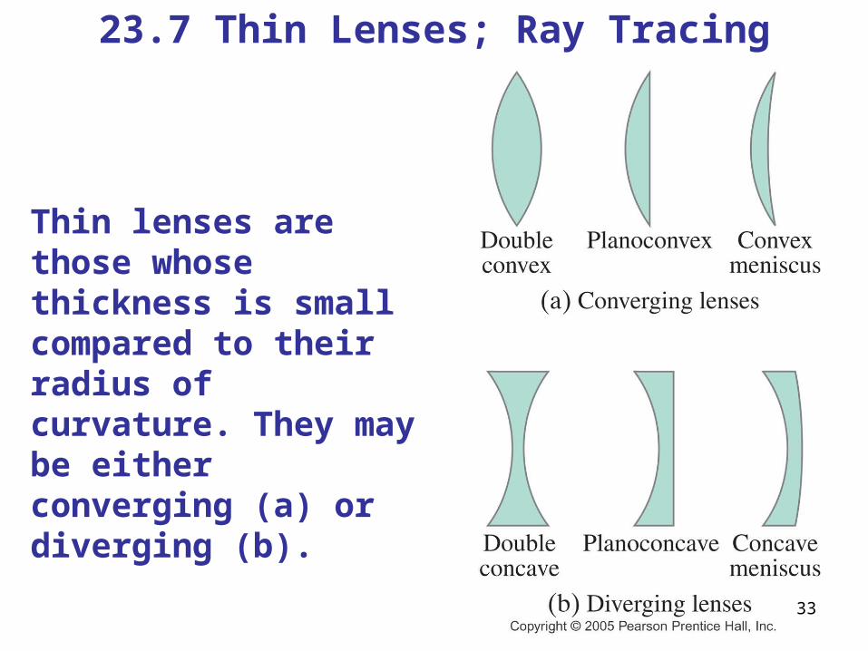
23.7 Thin Lenses; Ray Tracing
Thin lenses are those whose thickness is small compared to their radius of curvature. They may be either converging (a) or diverging (b).
33

3 Ray Brothers are back!
Ray 3 is the easiest ray to use
34

RTD for converging lens
• Image characteristics the same as for concave mirror
• real images form on EXIT side of lens, not on the “front” side as with mirrors.
35

virtual images form on ENTRANCE side of lens36
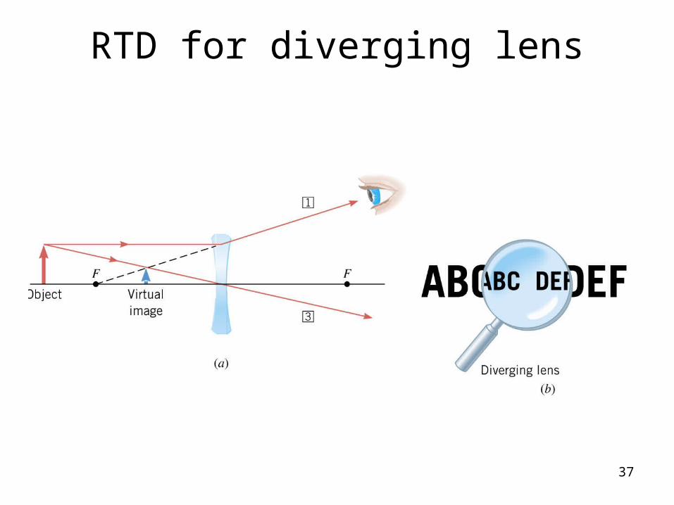
RTD for diverging lens
37

Sign Conventions for Lenses (p792)
+ do real object XXXXXX
di real image
(exit side)
virtual image(entrance side)
f converging diverging
hi upright image inverted image
m upright image inverted image
m > 1.0 larger image m =1.0 same size m < 1.0 smaller image
38

23.9 Combinations of Lenses
In lens combinations, the image formed by the first lens becomes the object for the second lens (this is where object distances may be negative).
39
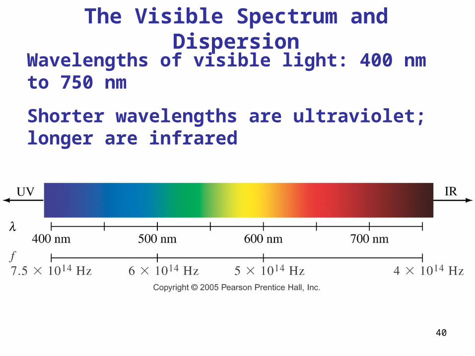
The Visible Spectrum and Dispersion
Wavelengths of visible light: 400 nm to 750 nm
Shorter wavelengths are ultraviolet; longer are infrared
40

The Visible Spectrum and Dispersion
The various wavelengths of visible light refract different amounts – another example of the wave nature of light
41

Formation of Rainbows
Actual rainbows are created by dispersion in tiny drops of water.
42
“I set My bow in the cloud, and it shall be for a sign of a covenant between Me and the earth.” Genesis 9:13

43

24.8 Interference by Thin Films
Another way path lengths can differ, and waves interfere, is if the travel through different media.
If there is a very thin film of material – a few wavelengths thick – light will reflect from both the bottom and the top of the layer, causing interference.
This can be seen in soap bubbles and oil slicks, for example. 44

45
3 things to account for in thin film interference problems
1) wavelength change due to speed of light decreasing compared to speed in air (vacuum) = 3 x 10⁸ m/s
2) constructive interference or destructive interference occurring at the top surface of the film
3) waves reflected at boundaries undergoing inversion or not due to index of refraction difference

24.8 Interference by Thin Films
The wavelength of the light will be different in the oil and the air. Index of refraction n is a measure of this speed change.
46
air air
film film
fcn
v f

47
Path length difference for interference
For the eye to see bright region at AC there must be a PLD = m m = 1,2,3..
For the eye to see a dark region at AC there must be a PLD = m(/2) m = 1, 3, 5..
There is always a PLD = 2t due to the transmitted wave 2 passing through the film and being reflected off the bottom surface.
Constructive: PLD = m= 2t
Destructive: PLD = m(/2) = 2t
BUT one more factor involved

48
There is a half cycle inversion when wave reflects from a higher index (n) medium, as at the air-to-gasoline boundary. Similar to rope fixed to a wall.
There is no inversion when wave reflects reflects from a lower index medium, as at the gasoline-to-water boundary. Similar to rope free to move at boundary.
Inversion of wave at boundary

49
There will be a /2 PLD between waves 1 and 2 due to inversion at top surface but not at second surface.
Constructive (bright spot)
PLD = m= 2t + /2 m = 1, 2, 3
Destructive (dark spot)
PLD = m(/2) = 2t + /2 m = 1, 3, 5

50
The PLD between waves 1 and 2 will only be due to the travel through the coating because the /2 inversion happens at both boundaries, so net result is they are both still in phase.
Constructive (bright spot)
PLD = m= 2t m = 1, 2, 3
Destructive (dark spot)
PLD = m(/2) = 2t m = 1, 3, 5
n = 1.2n = 1.5

24.8 Interference by Thin FilmsA similar effect takes place when a shallowly curved piece of glass is placed on a flat one. When viewed from above, concentric circles appear that are called Newton’s rings.
51