ap-3500 (acp enabled) - goarista.com · user manual ap-3500 (acp enabled) * intel atom n 270, 1.6...
TRANSCRIPT

USER MANUAL
AP-3500 (ACP Enabled)* INTEL ATOM N 270, 1.6 GHz* UP TO 2GB DDR2-667 SODIMM* ACP ENABLED VERSION* DUAL MONITOR VGA + DVI* VESA MOUNTING BRACKET (OPTIONAL)

Contents
Product safety precautions .............................................................................................1FCC declaration of conformity ........................................................................................1Copyright 2014..................................................................................................................2Disclaimer .........................................................................................................................2Features.............................................................................................................................3Applications ......................................................................................................................3Unpacking .........................................................................................................................3Product Overview .............................................................................................................4
I/O panel .......................................................................................................................4VGA pin description .........................................................................................................5DVI pin description ...........................................................................................................6Physical dimensions .......................................................................................................7Installing ............................................................................................................................8Connecting to a display ...................................................................................................10
1. Connect to a display via DVI cable. ..........................................................................102. Connect to a display via VGA cable. ........................................................................10
Connecting a keyboard and a mouse .............................................................................11Connecting to a network ..................................................................................................12Connecting earphones/headphones or speakers .........................................................12Connecting the power adapter ........................................................................................13Using BIOS ........................................................................................................................14
About the setup utility ...................................................................................................14The standard configuration .....................................................................................14Entering the setup utility ..........................................................................................14BIOS navigation keys ..............................................................................................15
Using BIOS ...................................................................................................................15Standard CMOS Features .......................................................................................16Advanced BIOS Features .......................................................................................18Advanced Chipset Features ....................................................................................23Integrated Peripherals .............................................................................................26Power Management Setup ......................................................................................31PnP/PCI Configurations ..........................................................................................34PC Health Status .....................................................................................................35Load Fail-Safe Defaults Option ...............................................................................36Load Optimized Defaults Option .............................................................................36Set Supervisor/User Password ...............................................................................36Save & Exit Setup ...................................................................................................37Exit Without Saving .................................................................................................37
Specifications ...................................................................................................................38

Maintenance ......................................................................................................................391. Maintenance. ............................................................................................................392. Product Limited Warranty. ........................................................................................393. Technical Support. ....................................................................................................404. RMA Procedures. .....................................................................................................405. RMA Credit Policy. ....................................................................................................416. RMA Transportation Policy. ......................................................................................417. RMA Shipping Instruction. ........................................................................................428. Arista’s Limited Liability. ............................................................................................439. Disclaimer. ................................................................................................................43

1
Product safety precautionsRead all of these instructions and save this manual for later use. Follow all warnings and instructions concerning the product.• Do not cover or block the ventilation holes in the enclosure. • Do not insert sharp objects or spill liquids into AP-3500 through the openings of its
enclosure.Thismaycauseanaccidentalfire,electricshockorfailure.• Unplug the unit when not in use for an extended period of time. • Consult a service technician if the AP-3500 does not operate normally when you have
followed the instructions in this manual. • Donotattempttorepairthisproductyourself.Alwaysgetaqualifiedservicetechnicianto
carry out adjustments or repairs.• Use only the power cord supplied with the unit. In the event that another power cord is used,
onethatisdifferentthantheoneprovidedbythesupplier,makesurethatitiscertifiedbythe local and applicable national standards. If the power cable is faulty in any way, please contact the manufacturer or the nearest authorized repair service provider for a replacement.
• The power supply cord is used as the main disconnect device. Ensure that the socket outlet is easily accessible after installation.
• Overloaded AC outlets, extension cords, frayed power cords, and broken plugs are extremelydangerous.Theymay,andcan,resultinanelectricalshockorfirehazard.Callanauthorized service technician for any replacements.
• Hands must be dry when plugging in the power cord into an AC outlet to prevent electrical shock. Do not damage the power cord by disassembling, bending, pulling or exposing it to heatasitmaycauseafireorelectricalshock.
• Makesuretocompletelyinsertthepowerplug.Insecureconnectionscancausefires.• Unplug the AP-3500 if cleaning or maintenance is needed. The unit may only be cleaned
with a dry cloth. Never use alcohol, solvents or ammonia-based liquids. • Do not subject the AP-3500 to severe vibration or high impact conditions.
Note: This equipment has been tested and found to comply with the limits for a Class B digital device, pursuant to Part 15 of the FCC Rules. These limits are designed to provide reasonable protection against harmful interference in a residential installation. This equipment generates, uses, and can radiate radio frequency energy and, if not installed and used in accordance with the instructions, may cause harmful interference to radio communications. However, there is no guarantee that interference will not occur in a particular installation. If this equipment does cause harmful interference to radio or television reception, which can be determined by turning the equipment off and on the user is encouraged to try and correct the interference by one or more of the following measures:
- Reorient or locate the receiving antenna.- Increase the separation between the equipment and receiver- Connect the equipment into an outlet on a circuit different from that to which the receiver is
connected- Consult the dealer or an experienced radio/TV technician for help
FCC declaration of conformity

2
FCC declaration of conformityThe information contained in this user’s manual and all accompanying documentation is copyrighted and all rights are reserved. This publication may not, in whole or in part, be reproduced, transcribed, stored in a retrieval system, translated into any language or computer language, or transmitted in any form whatsoever without the prior written consent from the manufacturer, except for copies retained by the purchasers for their personal archival purposes. The manufacturer reserves the right to revise this user’s manual and all accompanying documentation and to make changes in the content without obligation to notify any person or organization of the revision or change.
IN NO EVENT WILL THE VENDOR BE LIABLE FOR DIRECT, INDIRECT, SPECIAL, INCIDENTAL, OR CONSEQUENTIAL DAMAGES ARISING OUT OF THE USE OR INABILITY TO USE THIS PRODUCT OR DOCUMENTATION; EVEN IF ADVISED OF THE POSSIBILITY OF SUCH DAMAGES. IN PARTICULAR, THE VENDOR SHALL NOT HAVE LIABILITY FOR ANY HARDWARE, SOFTWARE, OR DATA STORED OR USED WITH THE PRODUCT, INCLUDING THE COSTS OF REPAIRING, REPLACING,OR RECOVERING SUCH HARDWARE, SOFTWARE, OR DATA.
All trademarksmentioned in thisdocumentareacknowledged.Thespecifications in thismanual are subject to change without notice.
© Copyright 2014
Disclaimer• Specificationsandinformationcontained inthismanualarefurnishedfor informational
use only and subject to change without notice, and should not be constructed as a commitment by Arista. Arista assumes no responsibility for any errors or omissions that may appear in this manual.
• With respect to the contents of this manual, Arista does not provide warranty of any kind, either expressed or implied, including but not limited to the implied warranties or conditionsofmerchantabilityorfitnessforaparticularpurpose.
• InnoeventshallArista, itsdirectors,officers,employees,oragentsbe liable foranyindirect, special, incidental, or consequential damages (including damages for loss of profits,lossofbusiness,lossofdata,interruptionofbusinessandthelike),evenifAristahas been advised of the possibility of such damages arising from any defect or error in the manual or product.
CALIFORNIA, USA ONLYThe Lithium battery adopted on this motherboard contains Perchlorate, a toxic substance controlled in Perchlorate Best Management Practices (BMP) regulations passed by the California Legislature. When you discard the Lithium battery in California, USA, please follow the related regulations in advance.“Perchlorate Material-special handling may apply, see www.dtsc.ca.gov/hazardouswaste perchlorate”
CAUTION: RISK OF EXPLOSION IF BATTERY IS REPLACED BY AN INCORRECT TYPE.
DISPOSE OF USED BATTERIES ACCORDING TO THE INSTRUCTIONS.

3
Features
• Intel Atom N 270, 1.6 GHz• UP to 2GB DDR2-667 SODIMM• ACP Enabled Version• Dual monitor VGA + DVI• VESA Mounting Bracket (optional)
•ApplicationsThe product covered herein are designed and manufactured for following application areas.• Officeelectronics• Instrumentation and measuring equipment• Machine tools• Audiovisual equipment• Home appliances• Communication equipment other than trunk lines • Do not use the products covered herein for the following equipment that demands
extremely high performance in terms of functionality, reliability, or accuracy.• Aerospace equipment• Communication equipment for trunk lines• The board is not user serviceable or repairable. Warranty does not cover user error in
connectinguptothecontrollerandisinvalidatedbyunauthorizedmodificationorrepairs.
Unpacking
Unpack the contents and inspect the items closely to make sure no item is damaged and all items listed are present in your package:
adapter x1 AC power cord x1 Drive CD rom x1AP-3500 (ACP Enabled) x1

4
Product Overview
I/O panel
1 2 x USB2.0 port 2 DVI port 3 VGA connector 4 2 x LAN RJ-45 Port 5 PS/2 Mouse/Keyboard Port
6 12V DC input 7 Power button 8 2 x USB 2.0 port 9 Earphone/headphone jack10 Microphone jack
There are two LEDs on each LAN port. Please refer to the table below for the LAN port LED indications.
Activity/Link LED
SPEED LED
LAN Port LED IndicationsActivity/Link LED SPEED LEDStatus Description Status DescriptionOff No Link Off 10Mbps connectionBlinking Data Activity Orange 100Mbps connectionOn 100Mbps connection Green 1Gbps connection
7
8 910
1
2
3
4
5 6

5
VGA pin description
1
2
3
4
5
6
7
8
9
10
11
12
13
14
15
VGA signal input connectorPin NO. Pin Assignment Pin Description Remark
1 VGA R VGA Red signal2 VGA G VGA Green signal3 VGA B VGA Blue signal4 NC No connection5 GND Ground6 GND Ground7 GND Ground8 GND Ground9 NC No connection
10 GND Ground11 NC No connection12 CRT DDC Data The data of display data channel13 VGA HS VGA H-Sync signal14 VGA VS VGA V-Sync signal15 CRT DDC Clock The clock of display data channel

6
DVI pin description
DVI signal input connectorPin NO. Pin Description Pin NO. Pin Description
1 T.M.D.S _ Data 2- 16 Hot plug _ detect2 T.M.D.S _ Data 2+ 17 T.M.D.S _ Data 0-3 Ground 18 T.M.D.S _ Data 0+4 N/A 19 Ground5 N/A 20 N/A6 DDC _ clock 21 N/A7 DDC _ data 22 Ground8 Analog _ VSYNC 23 T.M.D.S _ Clock +9 T.M.D.S _ Data 1- 24 T.M.D.S _ Clock -
10 T.M.D.S _ Data 1+ C1 Analog _ RED11 Ground C2 Analog _ Green12 N/A C3 Analog _ Blue13 N/A C4 Analog _ HSYNC14 + 5V power input C5 Analog ground15 Ground
8
1234567
1011121314151624
C1
C2
C3
C4C5
23222120191817 9

7
Physical dimensions The following diagram depicts the dimensions of the AP-3500.
Model Number W1 L1 H1 W2 L2 H2 WeightAP-3500
(ACP Enabled) 2.77" 7.14" 9.31" 1.76" 6.00" 8.74" 0.91 KG
H1: 9.31"
H2: 8.74"
L1: 7.14"
L2: 6.00"W1: 2.77"
W2:1.76"

8
InstallingThis unit can be placed on a shelf or table, or mounted onto the back of a computer screen. Refer to the illustration below to mount the unit onto the back of a computer screen.
Screw holes
1. Locate the four screw holes in the back of the computer screen.
2. Fix the mount panel (optional) to the back of the screen with screws.

9
3. Slide the base bracket to remove it from the unit.
Base bracket
4. Push the unit into the mount panel until the panel clicks and locks the unit in place.
Slide
5. To uninstall the unit, press the two irons (with springs) simultaneously on both sides to release the unit.

10
Connecting to a display
NospecifictoolsarerequiredtoconnecttheAP-3500toadisplayormonitor.Simplyfollowtheseinstructions outlined in the diagram below.
1. Connect to a display via DVI cable
:Signalflow
:Signalflow
ARISTA ADM-1815 Display (SOLD SEPERATELY)
ARISTA ADM-1815 Display (SOLD SEPERATELY)
DVI cable (not supplied)
2. Connect to a display via VGA cable
VGA cable (not supplied)
AP-3500 (ACP Enabled)
AP-3500 (ACP Enabled)

11
AP-3500 (ACP Enabled)
AP-3500 (ACP Enabled)
Figure 1 shows how to connect a USB keyboard and mouse and Figure 2 shows how to connect a PS/2 keyboard and mouse.
Connecting a keyboard and a mouse
Figure 1
Figure 2

12
AP-3500 (ACP Enabled)
Modem
• Connect earphones/headphones or speakers with a 3.5mm audio cable (NOT INCLUDED).
• Connect one end of the network cable (not supplied) to the LAN port of your PC, and connect the other end to the broadband modem or router.
LAN cable (not supplied)
3.5mm audio cable (NOT INCLUDED)
Note: If you are using supplied cables and accessories, ensure that they are correct for the unit.
Connecting to a network
Connecting earphones/headphones or speakers

13
• Connect the round shape plug end of the AC/DC adapter to the DC Power input connector of the AP-3500. Connect the female end of the power cable to the AC power input receptacle on the AC/DC adapter. Then plug the male end of the power cable into an AC outlet.
AC/DC power adapter and cable (supplied)
Connecting the power adapter
AP-3500 (ACP Enabled)
Note: If you are using supplied cables and accessories, ensure that they are correct for the unit.
The12VdcinputisforconnectiontoasuitableCertified,SELV-LPSor(US)NECClassAC adapter.

14
Using BIOS
Award’s BIOS ROM has a built-in Setup program that allows user to modify the basic system configuration.Thistypeofinformationisstoredinbattery-backedCMOSRAMsothatitretainsthe Setup information when the power is turned off.
About the setup utility
The standard configuration AstandardconfigurationhasalreadybeensetintheSetupUtility.However,werecommendthatyou read this chapter in case you need to make any changes in the future.
This Setup Utility should be used:•whenaconfigurationerrorisdetectedandyouarepromptedtomakechangestotheSetupUtility•whentryingtoresolveIRQconflicts•whenmakingchangestothePowerManagementconfiguration•whenchangingthepasswordormakingotherchangestotheSecuritySetup
Entering the setup utilityPower on the computer and press <Del> immediately. This will allow you to enter Setup.
The default BIOS setting for this motherboard apply for most conditions with optimum performance. We do not suggest users change the default values in the BIOS setup and take no responsibility to any damage caused by changing the BIOS settings.
Phoenix-AwardBIOS CMOS Setup Utility
Standard CMOS Features
Advanced BIOS Features
Advanced Chipset Features
Integrated Peripherals
Power Management Setup
PnP/PCIConfigurations
PC Health Status
Load Fail-Safe Defaults
Load Optimized Defaults
Set Supervisor Password
Set User Password
Save & Exit Setup
Exit Without Saving
Time, Date, Hard Disk Type...
Esc : Quit
F10 : Save & Exit Setup
: Select Item

15
BIOS navigation keys
The BIOS navigation keys are listed below:
When you start the Setup Utility, the main menu appears. The main menu of the Setup Utility displays a list of the options that are available. A highlight indicates which option is currently selected. Use the cursor arrow keys to move the highlight to other options. When an option is highlighted, execute the option by pressing <Enter>.
Some options lead to pop-up dialog boxes that prompt you to verify that you wish to execute that option. Other options lead to dialog boxes that prompt you for information.
Some options (marked with a triangle ) lead to submenus that enable you to change the values for the option. Use the cursor arrow keys to scroll through the items in the submenu.
In this manual, default values are enclosed in parenthesis. Submenu items are denoted by a triangle .
Using BIOS
KEY FUNCTIONESC Exits the current menu
Scrolls through the items on a menu+/-/PU/PD Modifiestheselectedfield’svalues
F10 SavesthecurrentconfigurationandexitssetupF1 Displays a screen that describes all key functionsF5 Loads previously saved values to CMOSF6 LoadsaminimumconfigurationfortroubleshootingF7 Loads an optimum set of values for peak performance

16
Standard CMOS Features
When you choose the Standard CMOS Features option from the Initial Setup Screen menu, the screenshownbelowisdisplayed.ThisstandardSetupMenuallowsuserstoconfiguresystemcomponentssuchasdate,time,harddiskdrive,floppydriveanddisplay.Onceafieldishighlighted,on-line help information is displayed on the right of the Menu screen.
Date and Time
The Date and Time items show the current date and time on the computer. If you are running a Windows OS, these items are automatically updated whenever you make changes to the Windows Date and Time Properties utility.
SATA Devices
This motherboard features two SATA connectors supporting two SATA drives. SATA refers to Serial ATA (Advanced Technology Attachment), the standard interface for the IDE hard drives which are currently used in most PCs.
Phoenix-AwardBIOS CMOS Setup UtilityStandard CMOS Features
Menu Level
: Move
Date (mm:dd:yy) Thu. May 22 2014Time (hh:mm:ss) 11 : 5 : 34
Serial ATA Channel 1 [None]Serial ATA Channel 2 [None]
Video [EGA/VGA]Halt On [All Errors]
Base Memory 640KExtended Memory 2086912KTotal Memory 2087936K
Item Help
Change the internalclock
Enter: Select F10: Save ESC: Exit F1: General Help
F5: Previous Values F6: Fail-Safe Defaults F7: Optimized Defaults
+/-/PU/PD: Value
Phoenix-AwardBIOS CMOS Setup UtilitySerial ATA Channel 1
Menu Level
IDE HDD Auto-Detection [Press Enter]
Serial ATA Channel 1 [Auto]Access Mode [Auto]
To auto-detect the HDD’s size, head...on this channel
Capacity 0 MB
Cylinder 0Head 0Precomp 0Landing Zone 0Sector 0
Item Help
: Move Enter: Select F10: Save ESC: Exit F1: General Help
F5: Previous Values F6: Fail-Safe Defaults F7: Optimized Defaults
+/-/PU/PD: Value

17
IDE HDD Auto-Detection
Press <Enter> while this item is highlighted to prompt the Setup Utility to autumatically detect and configureanIDEdeviceontheIDEchannel.
Serial ATA Channel 1/2 (Auto)
LeavethisitematAutotoenablethesystemtoautomaticallydetectandconfigureSATAdevicesonthechannel.Ifitfailstofindadevice,changethevaluetoManualandthenmanuallyconfigurethe drive by entering the characteristics of the drive in the items described below.
Refer to your drive's documentation or look on the drive casing if you need to obtain this information. If no device is installed, change the value to None.
Before attempting to configure a hard disk drive, ensure that you have the configuration information supplied by the manufacturer of your hard drive. Incorrect settings can result in your system not recognizing the installed hard disk.
Access Mode (Auto)
ThisitemdefineswaysthatcanbeusedtoaccessSATAharddisks.LeavethisvalueatAutoandthe system will automatically decide the fastest way to access the hard disk drive.
Video (EGA/VGA)Thisitemdefinesthevideomodeofthesystem.Thismotherboardhasabuilt-inVGAgraphicssystem; you must leave this item at the default value.
Halt On (All Errors)
Press <Esc> to return to the Standard CMOS Features page.
Press <Esc> to return to the main menu setting page.

18
Advanced BIOS Features
Thissectionallowsyou toconfigureand improveyoursystemandallowsyou tosetupsomesystem features according to your preference.
Phoenix-AwardBIOS CMOS Setup UtilityAdvanced BIOS Features
Menu Level
: Move
CPU Feature [Press Enter]Hard Disk Boot Priority [Press Enter]Virus Warning [Disabled]CPU L1 & L2 Cache [Enabled]CPU L3 Cache [Enabled]Hyper-Threading Technology [Enabled]Quick Power On Self Test [Enabled]First Boot Device [Hard Disk]Second Boot Device [CD ROM]Third Boot Device [USB-CDROM]Boot Other Device [Enabled]Boot Up NumLock Status [On]Gate A20 Option [Fast]Typematic Rate Setting [Disabled]Typematic Rate (Chars/Sec0 6Typematic Delay (Msec) 250Security Option [Setup]APIC Mode EnabledMPS Version Control For OS [1.4]
Item Help
Enter: Select F10: Save ESC: Exit F1: General Help
F5: Previous Values F6: Fail-Safe Defaults F7: Optimized Defaults
+/-/PU/PD: Value
xx
x
Phoenix-AwardBIOS CMOS Setup UtilityAdvanced BIOS Features
Menu Level
: Move
CPU L3 Cache [Enabled]Hyper-Threading Technology [Enabled]Quick Power On Self Test [Enabled]First Boot Device [Hard Disk]Second Boot Device [CD ROM]Third Boot Device [USB-CDROM]Boot Other Device [Enabled]Boot Up NumLock Status [On]Gate A20 Option [Fast]Typematic Rate Setting [Disabled]Typematic Rate (Chars/Sec0 6Typematic Delay (Msec) 250Security Option [Setup]APIC Mode EnabledMPS Version Control For OS [1.4]OS Select For DRAM >64MB [Non-OS2]Report No FDD For WIN 95 [No]Full Screen LOGO Show [Enabled]Small Logo (EPA) Show [Disabled]
Item Help
Enter: Select F10: Save ESC: Exit F1: General Help
F5: Previous Values F6: Fail-Safe Defaults F7: Optimized Defaults
+/-/PU/PD: Value
xx
x
19
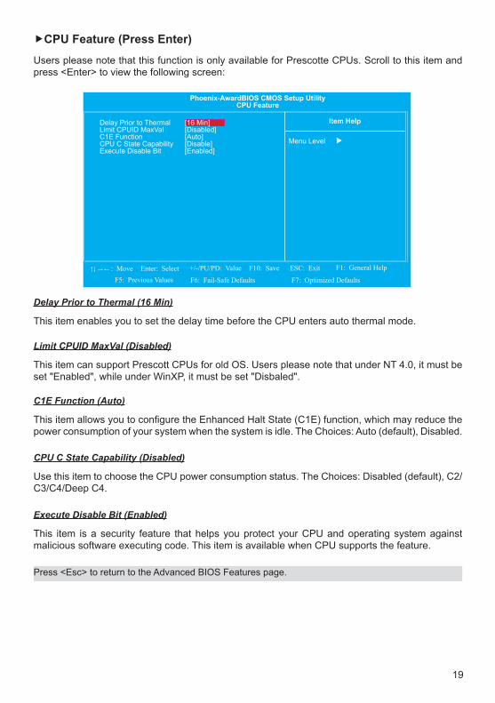
CPU Feature (Press Enter)
Users please note that this function is only available for Prescotte CPUs. Scroll to this item and press <Enter> to view the following screen:
Delay Prior to Thermal (16 Min)
This item enables you to set the delay time before the CPU enters auto thermal mode.
Limit CPUID MaxVal (Disabled)
This item can support Prescott CPUs for old OS. Users please note that under NT 4.0, it must be set "Enabled", while under WinXP, it must be set "Disbaled".
Phoenix-AwardBIOS CMOS Setup UtilityCPU Feature
Menu Level
Delay Prior to Thermal [16 Min]Limit CPUID MaxVal [Disabled]C1E Function [Auto]CPU C State Capability [Disable]Execute Disable Bit [Enabled]
Item Help
: Move Enter: Select F10: Save ESC: Exit F1: General Help
F5: Previous Values F6: Fail-Safe Defaults F7: Optimized Defaults
+/-/PU/PD: Value
C1E Function (Auto)
ThisitemallowsyoutoconfiguretheEnhancedHaltState(C1E)function,whichmayreducethepower consumption of your system when the system is idle. The Choices: Auto (default), Disabled.
CPU C State Capability (Disabled)
Use this item to choose the CPU power consumption status. The Choices: Disabled (default), C2/C3/C4/Deep C4.
Execute Disable Bit (Enabled)
This item is a security feature that helps you protect your CPU and operating system against malicious software executing code. This item is available when CPU supports the feature.
Press <Esc> to return to the Advanced BIOS Features page.

20
Hard Disk Boot Priority (Press Enter)
Scroll to this item and press <Enter> to view the following screen:
Virus Warning (Disabled)Thisoptionflashesonthescreen.Duringandafterthesystembootup,anyattempttowritetotheboot sector or partition table of the hard disk drive will halt the system with the following message. You can run an anti-virus program to locate the problem. The default setting is "Disabled".
CPU L1 & L2 Cache (Enabled)
These two options speed up memory access. However, it depends on the CPU/chipset design. The default setting is "Enabled". CPUs with no built-in internal cache will not provide the "CPU Internal Cache" item on the menu.
CPU L3 Cache (Enabled)
This item is only available when processors support L3. Some high-end processors support L3. If the CPU do support L3, you may set this item to enable or disable. Leave this item at the default value for better performance.
Phoenix-AwardBIOS CMOS Setup UtilityHard Disk Boot Priority
Menu Level
1. Bootable Add-in Cards Item Help
: Move Enter: Select F10: Save ESC: Exit F1: General Help
F5: Previous Values F6: Fail-Safe Defaults F7: Optimized Defaults
+/-/PU/PD: Value
Use < > or < > to select a device, then press <+> to move it down the list. Press <ESC> to exit this menu.
Press <Esc> to return to the Advanced BIOS Features page.
Hyper-Threading Technology (Enabled)
This item is only available when the chipset supports Hyper-Threading and you are using a Hyper-Threading CPU.
Quick Power on Self Test (Enabled)
Enable this item to shorten the power on self testing (POST) and have your system start up faster. Youmightliketoenablethisitemafteryouareconfidentthatyoursystemhardwareisoperatingsmoothly.

21
Boot Other Device (Enabled)
When enabled, the system searches all other possible locations for an operating system if it fails tofindoneinthedevicesspecifiedundertheFirst,Second,andThirdbootdevices.
Boot Up MumLock Status (On)
ThisitemdefinesifthekeyboardNumLockkeyisactivewhenyoursystemisstarted.
Gate A20 Option (Fast)
Thisitemdefineshowthesystemhandleslegacysoftwarethatwaswrittenforanearliergenerationof processors. Leave this item at the default value.
Typematic Rate Setting (Disabled)
If this item is enabled, you can use the following two items to set the typematic rate and the typematic delay settings for your keyboard.
• Typematic Rate (Chars/Sec): Use this item to define how many characters per second are generated by a held-down key.
• Typematic Delay (MSec): Use this item to define how many milliseconds must elapse before a held-down key begins generating repeat characters.
Security Option (Setup)
Ifyouhaveinstalledpasswordprotection,thisitemdefinesifthepasswordisrequiredatsystemstart up, or if it is only required when a user tries to enter the Setup Utility.
First/Second/Third Boot Device (Hard Disk/CDROM/USB-CDROM)
Use these three items to select the priority and order of the devices that your system searches for an operating system at start-up time.
• APIC Mode (Enabled): This item allows you to enable or disable the APIC (Advanced Programmable Interrupt Controller) mode. APIC provides symmetric multi-processing (SMP) for systems, allowing support for up to 60 processors.
MPS Version Control for OS (1.4)
TheBIOSsupportsversion1.1and1.4oftheIntelmultiprocessorspecification.Selectversionsupported by the operation system running on this computer. The Choices: 1.4 (default), 1.1.
OS Select For DRAM >64MB (Non-OS2)
This item is only required if you have installed more than 64 MB of memory and you are running the OS/2 operating system. Otherwise, leave this item at the default.
Peport No FDD For WIN 95 (No)
SetthisitemtothedefaultifyouarerunningasystemwithnofloppydriveandusingWindows95;thisensurescompatibilitywiththeWindows95logocertification.

22
Full Screen LOGO Show (Enabled)
Allows you to determine whether to display the manufacturer's Logo at system startup. Disable it to display normal POST message.
Small Logo (EPA) Show (Disabled)
This item enables or disables the display of the EPA logo during boot.
Press <Esc> to return to the main menu setting page.

23
Advanced Chipset Features
Since the features in this section are related to the chipset on the CPU board and are completely optimized, you are not recommended to change the default settings in this setup table unless you are well oriented with the chipset features.
DRAM Timing Selectable (By SPD)
The value in this feild depends on performance parameters of the installed memory chips (DRAM). Do not change the value from the factory setting unless you install new memory that has a different performance rating than the original DRAMs.
CAS Latency Time (Auto): When synchronous DRAM is installed, the number of clock cycles of CAS latency depends on the DRAM timing. Do not reset this field from the default value specified by the system designer.
DRAM RAS# to CAS# Delay (Auto): This field allows you insert a timing delay between the CAS and RAS strobe signals, used when DRAM is written to, read from, or refreshed. Disabled gives faster performance; and Enabled gives more stable performance.
DRAM RAS# Precharge (Auto): Select the number of CPU clocks allocated for the Row Address Strobe (RAS#) signal to accumulate its charge before the DRAM is refreshed. If insufficient time is allowed, refresh may be incomplete and data lost.
Precharge Delay (tRAS) (Auto): The precharge time is the number of cycles it takes for DRAM to accumulate its charge before refresh.
System Memory Frequency (Auto): This item sets the main memory frequency. When you use an external graphics card, you can adjust this to enable the best performance for your system.
•
•
•
•
•
Phoenix-AwardBIOS CMOS Setup UtilityAdvanced Chipset Features
Menu Level
: Move
DRAM Timing Selectable [By SPD]CAS Latency Time [Auto]DRAM RAS# to CAS# Delay [Auto]DRAM RAS# Precharge [Auto]Precharge delay (tRAS) [Auto]System Memory Frequency [Auto]SLP_S4# Assertion Width [4 to 5 Sec.]System BIOS Cacheable [Enabled]Video BIOS Cacheable [Disabled]Memory Hole At 15M-16M [Disabled]PCI Express Root Port Func [Press Enter]
** VGA Setting **On-Chip Frame Buffer Size [8MB]DVMT Mode [DVMT]DVMT/FIXED Memory Size [128MB]Boot Display [Auto]
Item Help
Enter: Select F10: Save ESC: Exit F1: General Help
F5: Previous Values F6: Fail-Safe Defaults F7: Optimized Defaults
+/-/PU/PD: Value
xxxxx

24
SLP_S4# Assertion Width (4 to 5 Sec.)
This item selects a minimum assertion width of the SLP_S4# signal.
System BIOS Cacheable (Enabled)
This item allows the system to be cached in memory for faster execution. Enable this item for better performance.
Video BIOS Cacheable (Disabled)
The item allows the video BIOS to be cached in memory for faster execution.
Memory Hole At 15M-16M (Disabled)
You can reserve this area of system memory for ISA adapter ROM. When this area is reserved, it cannot be cached. The user information of peripherals that need to use this area of system memory usually discusses their memory requirements. The default value is "Disabled".
PCI Express Root Port Func (Press Enter)
Scroll to this item and press <Enter> to view the following screen:
PCI Express 1/2/3/4 (Auto)
This item allows you to enable/disable the PCI Express port. The Choices: Auto (default), Disabled.
PCI-E Compliancy Mode (v1.0a)
This item allows you to select the PCI-E Compliancy Mode. The Choices: v1.0a (default), v1.0.
Phoenix-AwardBIOS CMOS Setup UtilityPCI Express Root Port Func
Menu Level
PCI Express Port 1 [Auto]PCI Express Port 2 [Auto]PCI Express Port 3 [Auto]PCI Express Port 4 [Auto]PCI-E Compliancy mode [v1.0a]
Item Help
: Move Enter: Select F10: Save ESC: Exit F1: General Help
F5: Previous Values F6: Fail-Safe Defaults F7: Optimized Defaults
+/-/PU/PD: Value
Press <Esc> to return to the Advanced Chipset Features page.

25
On-Chip Frame Buffer Size (8MB)
This item will be different as your memory modules. When the memory size is decided, this frame buffersizewillalsobefixed.TheChoices:8MB(default),1MB.
DVMT Mode (DVMT)
This item allows you to select the DVMT operating mode.
DVMT/FIXED Memory Size (128MB)
WhensettoFixedMode,thegraphicsdriverwillreserveafixedportionofthesystemmemoryasgraphics memory. When set to DVMT Mode, the graphics chip will dynamically allocate system memory as graphics memory, according to system and graphics requirements.
Boot Display (Auto)
This item is to set the system display device during boot up and the value may be updated according to the setting of OS driver.
Press <Esc> to return to the main menu setting page.

26
Integrated Peripherals
Theseoptionsdisplayitemsthatdefinestheoperationofperipheralcomponentsonthesystem'sinput/output ports.
Onchip IDE Devices (Press Enter)
Scroll to this item and press <Enter> to view the following screen:
IDE HDD Block Mode (Enabled)
Block mode is also called block transfer, multiple commands, or multiple sector read/write. If your IDE hard drive supports block mode (most new drives do), select Enabled for automatic detection of the optimal number of block read/writes per sector the drive can support.
Phoenix-AwardBIOS CMOS Setup UtilityIntegrated Peripherals
Menu Level
: Move
OnChip IDE Device [Press Enter]Onboard Device [Press Enter]Super IO Device [Press Enter]USB Device Setting [Press Enter]
Item Help
Enter: Select F10: Save ESC: Exit F1: General Help
F5: Previous Values F6: Fail-Safe Defaults F7: Optimized Defaults
+/-/PU/PD: Value
Phoenix-AwardBIOS CMOS Setup UtilityOnChip IDE Devices
Menu Level
: Move
IDE HDD Block Mode [Enabled]IDE DMA transfer access [Enabled]On-Chip Primary PCI IDE [Enabled]IDE Primary Master PIO [Auto]IDE Primary Slave PIO [Auto]IDE Primary Master UltraDMA [Auto]IDE Primary Slave UltraDMA [Auto]
Item Help
Enter: Select F10: Save ESC: Exit F1: General Help
F5: Previous Values F6: Fail-Safe Defaults F7: Optimized Defaults
+/-/PU/PD: Value
If your IDE hard drive supports block mode select Enabled for automatic detection of the optimal number ofblock read/writes per sector the drive can support

27
On-Chip Primary PCI IDE (Enabled)
The integrated peripheral controller contains an IDE interface with support for two IDE channels. Select Enabled to activate each channel separately.
IDE Primary Master/Slave PIO (Auto)
Each IDE channel supports a master device and a slave device. These four items let you assign which kind of PIO (Programmed Input/Output) is used by IDE devices. Choose Auto to let the system auto detect which PIO mode is best, or select a PIO mode from 0-4.
IDE Primary Master/Slave UDMA (Auto)
This mainboard supports UltraDMA technology, which provides faster access to IDE devices. If you install a device that supports UltraDMA, change the item on this list to Auto. You may have to install the UltraDMA driver supplied with this mainboard in order to use an UltraDMA device.
Onboard Device (Press Enter)
Scroll to this item and press <Enter> to view the following screen:
HD Audio Select (Enabled)
Select [Auto], [Enabled] or [Disabled] for the onboard HD Audio feature. If you select [Auto], the onboard HD Audio will be disabled when PCI Sound Card is plugged.
Onboard Lan Boot ROM (Disabled)
This item allows you to enable or disable the onboard LAN Boot ROM function.
IDE DMA transfer access (Enabled)
This item allows you to enabled the transfer access of the IDE DMA.
Phoenix-AwardBIOS CMOS Setup UtilityOnboard Device
Menu Level
HD Audio Select [Enabled]Onboard Lan Boot ROM [Disabled]
Item Help
: Move Enter: Select F10: Save ESC: Exit F1: General Help
F5: Previous Values F6: Fail-Safe Defaults F7: Optimized Defaults
+/-/PU/PD: Value
Press <Esc> to return to the Integrated Peripherals page.
Press <Esc> to return to the Integrated Peripherals page.

28
Super IO Device (Press Enter)
Scroll to this item and press <Enter> to view the following screen:
POWER ON Function (BUTTON ONLY)
This feature allows you to set the method by which your system can be turned on.
Watch Dog Timer Select (Disabled)
The watchdog timer makes the system auto-reset while it stops to work for a period. The integrated watchdog timer can be setup as system reset mode by program.
This setting is used to Enable or Disable the Watch Dog Timer function. It must be used in conjunction with the Watch Dog jumper. To enable, choose from 1, 2, 3, 4, 8, 15 or 30 min.
KB Power ON Password (Enter): Set the password when Power On by Keyboard is set to Password. Press <Enter> on this item and set a password with up to 5 characters and then press <Enter> to accept. To turn on the system, enter the password and press <Enter>.Note: To cancel the password, press <Enter> on this item. When prompted for the password, press <Enter> again without entering the password to clear the password settings.
Hot Key Power ON (Ctrl-F1): When the POWER ON Function is set to Hot KEY, use this item to set the hot key combination that turns on the system.
Onboard Serial Port 1 (3F8/IRQ4)
This option is used to assign the I/O address and interrupt request (IRQ) for onboard serial port 1 (COM1).
Onboard Parallel Port (378/IRQ7)
This option is used to assign the I/O address and interrupt request (IRQ) for the onboard parallel port.
•
•
Phoenix-AwardBIOS CMOS Setup UtilitySuper IO Device
Menu Level
POWER ON Function [BUTTON ONLY]KB Power ON Passward EnterHot Key Power ON Ctrl-F1Onboard Serial Port 1 [3F8/IRQ4]Onboard Parallel Port [378/IRQ7]Parallel Port Mode [SPP]EPP Mode Select EPP1.7ECP Mode Use DMA 3
Item Help
: Move Enter: Select F10: Save ESC: Exit F1: General Help
F5: Previous Values F6: Fail-Safe Defaults F7: Optimized Defaults
+/-/PU/PD: Value
xx
xx

29
EPP Mode Select (EPP 1.7)
Use this item to select the EPP Mode Type: EPP1.7 or EPP1.9.
Parallel Port Mode (SPP)
This option enables you to set the data transfer protocol for your parallel port. Options: SPP (Standard Parallel Port), EPP (Enhanced Parallel Port), ECP (Extended Capabilities Port), and ECP+EPP.
ECP Mode Use DMA (3)
When the onboard parallel port is set to ECP mode, the parallel port can use DMA3 or DMA1.
Press <Esc> to return to the Integrated Peripherals page.

30
USB Device Setting
Scroll to this item and press <Enter> to view the following screen:
USB 1.0 Controller (Enabled)
Enables or disables the onboard USB 1.0 controller. We recommend users keep the dafault value. Disabling it might cause the USB devices not to work properly.
USB 2.0 Controller (Enabled)
Enables or disables the onboard USB 2.0 controller. We recommend users keep the dafault value. Disabling it might cause the USB devices not to work properly.
USB Operation Mode (High Speed)Auto decide USB device operation mode. [High Speed]: If USB device was high speed device,then it operated on high speed mode. If USB device was full/low speed,then it operated on full/low speed mode. [Full/Low Speed]: All of USB device operated on full/low speed mode. The Choices: High Speed (default), Full/Low Speed.
USB Keyboard Function (Enabled)
Enable this item if you plan to use a keyboard connected through the USB port in a legacy operating system (such as DOS) that does not support Plug and Play.
USB Mouse Function (Enabled)
Enable this item if you plan to use a mouse connected through the USB port in a legacy operating system (such as DOS) that does not support Plug and Play.
Phoenix-AwardBIOS CMOS Setup UtilityUSB Device Setting
Menu Level
USB 1.0 Controller [Enabled]USB 2.0 Controller [Enabled]USB Operation Mode [High Speed]USB Keyboard Function [Enabled]USB Mouse Function [Enabled]USB Storage Function [Enabled]
*** USB Mass Storage Device Boot Setting ***
Item Help
: Move Enter: Select F10: Save ESC: Exit F1: General Help
F5: Previous Values F6: Fail-Safe Defaults F7: Optimized Defaults
+/-/PU/PD: Value
[Enable] or [Disable] Universal Host Controller Interface for Universal Serial Bus.
USB Storage Function (Enabled)
This item allows you to enable or disable the USB Storage Legacy Support.
Press <Esc> to return to the Integrated Peripherals page.

31
Power Management Setup
The Power Management Setup allows you to save energy of your system effectively. It will shut down the hard disk and turn OFF video display after a period of inactivity.
ACPI Function (Enabled)
Thisitemallowsyoutoenable/disabletheAdvancedConfigurationandPowerManagement(ACPI).The options available are Enabled, Disabled.
ACPI Suspend Type (S3(STR))
Usethisitemtodefinehowyoursystemsuspends.Inthedefault,S3(STR),thesuspendmodeis a suspend to RAM, i.e., the system shuts down with the exception of a refresh current to the system memory.
PowerManagement(UserDefine)
This option allows you to select the type (or degree) of power saving for Doze, Standby, and Suspend modes.
Phoenix-AwardBIOS CMOS Setup UtilityPower Management Setup
Menu Level
: Move
ACPI Function [Enabled]ACPI Suspend Type [S3(STR)]PowerManagement [UserDefine]Video Off Method [DPMS]Video Off In Suspend [Yes]Suspend Type [Stop Grant]MODEM Use IRQ [3]Suspend Mode [Disabled]HDD Power Down [Disabled]Soft-Off by PWR-BTTN [Instant-Off]PWRON After PWR-Fail [On]Wake Up by LAN [Disabled]Power On By Ring [Disabled]USB KB WakeUp From S3(S4) [Disabled]Resume by Alarm [Disabled]Date (of Month) Alarm 0Time (hh:mm:ss) 0: 0: 0
** Reload Global Timer Events **
Item Help
Enter: Select F10: Save ESC: Exit F1: General Help
F5: Previous Values F6: Fail-Safe Defaults F7: Optimized Defaults
+/-/PU/PD: Value
xx
Phoenix-AwardBIOS CMOS Setup UtilityPower Management Setup
Menu Level
: Move
MODEM Use IRQ [3]Suspend Mode [Disabled]HDD Power Down [Disabled]Soft-Off by PWR-BTTN [Instant-Off]PWRON After PWR-Fail [On]Wake Up by LAN [Disabled]Power On By Ring [Disabled]USB KB WakeUp From S3(S4) [Disabled]Resume by Alarm [Disabled]Date (of Month) Alarm 0Time (hh:mm:ss) 0: 0: 0
** Reload Global Timer Events **Primary IDE 0 [Disabled]Primary IDE 1 [Disabled]Secondary IDE 0 [Disabled]Secondary IDE 1 [Disabled]FDD, COM, LPT Port [Disabled]PCI PIRQ[A-D]# [Disabled]
Item Help
Enter: Select F10: Save ESC: Exit F1: General Help
F5: Previous Values F6: Fail-Safe Defaults F7: Optimized Defaults
+/-/PU/PD: Value
xx

32
Suspend Type (Stop Grant)
If this item is set to the default Stop Grant, the CPU will go into Idle Mode during power saving mode.
MODEM Use IRQ (3)
If you want an incoming call on a modem to automatically resume the system from a power-saving mode, use this item to specify the interrupt request line (IRQ) that is used by the modem. You might have to connect the fax/modem to the motherboard Wake On Modem connector for this feature to work.
Suspend Mode (Disabled)
Use this item to enable or disable the suspend mode function.
HDD Power Down (Disabled)
When enabled, the hard-disk drives will power down after a set time of system inactivity. All other devices remain active. The Choices: Disabled (default), 1 Min, 2 Min, 3 Min, 4 Min, 5 Min, 6 Min, 7 Min, 8 Min, 9 Min, 10 Min, 11 Min, 12 Min, 13 Min, 14 Min, 15Min.
Soft-Off by PWR-BTTN (Instant-Off)
UnderACPI(AdvancedConfigurationandPowermanagementInterface)youcancreateasoftwarepower down. In a software power down, the system can be resumed by Wake Up Alarms. This item lets you install a software power down that is controlled by the power button on your system. If the item is set to Instant-Off, then the power button causes a software power down. If the item is set to Delay 4 Sec. then you have to hold the power button down for four seconds to cause a software power down.
PWRON After PWR-Fail (On)
This item enables your computer to automatically restart or return to its last operating status after power returns from a power failure.
Wake Up by LAN (Disabled)
This item specifys whether the system will be awakened from power saving modes when activity orinputsignalofthespecifiedhardwareperipheralorcomponentisdetected.
Power On by Ring (Disabled)
The system can be turned off with a software command. If you enable this item, the system can automatically resume if there is an incoming call on the Modem. You must use an ATX power supply in order to use this feature.
Video off Method (DPMS)
Thisitemdefineshowthevideoispowereddowntosavepower.ThisitemissettoDPMS(DisplayPower Management Software) by default.
Video off In Suspend (Yes)
Thisoptiondefinesifthevideoispowereddownwhenthesystemisputintosuspendmode.

33
USB KB WakeUp From S3(S4) (Disabled)
This item allows you to enable/disable the USB device wakeup function from S3/S4 mode.
Resume by Alarm (Disabled)
Whenset toEnabled,additionalfieldsbecomeavailableandyoucanset thedate(dayof themonth), hour, minute and second to turn on your system. When set to 0 (zero) for the day of the month,thealarmwillpoweronyoursystemeverydayatthespecifiedtime.
**Reload Global Timer Events**
Global Timer (power management) events are I/O events whose occurrence can prevent the system from entering a power saving mode or can awaken the system from such a mode. In effect, the systemremainsalertforanythingthatoccurstoadevicethatisconfiguredasEnabled,evenwhenthe system is in a power-down mode.
Primary Secondary IDE 0/1 (Disabled)
When these items are enabled, the system will restart the power-saving timeout counters when any activity is detected on any of the drives or devices on the primary or secondary IDE channels.
FDD, COM, LPT Port (Disabled)
When this item is enabled, the system will restart the power-saving timeout counters when any activityisdetectedonthefloppydiskdrive,serialports,ortheparallelport.
PCI PIRQ[A-D]# (Disabled)
When this item is enabled, any activity from one of the listed devices wakes up the system.
Press <Esc> to return to the main menu setting page.

34
PnP/PCI Configurations
TheseoptionsconfigurehowPnP(PlugandPlay)andPCIexpansioncardsoperateinyoursystem.Both the the ISA and PCI buses on the motherboard use system IRQs (Interrup ReQuests) and DMAs (Direct Memory Access). You must set up the IRQ and DMA assignments correctly through thePnP/PCIConfigurationsSetuputilityforthemotherboardtoworkproperly.SelectingPnP/PCIConfigurationsonthemainprogramscreentodisplaythismenu:
Init Display First (PCI Slot)
This item allows you to choose the primary display card.
ResetConfigurationData(Disabled)
Ifyouenablethisitemandrestartthesystem,anyPlugandPlayconfigurationdatastoredintheBIOS Setup is cleared from memory.
Resources Controlled By (Auto(ESCD))
You should leave this item at the default Auto (ESCD). Under this setting, the system dynamically allocates resources to Plug and Play devices as they are required.If you cannot get a legacy ISA (Industry Standard Architecture) expansion card to work properly, you might be able to solve the problem by changing this item to Manual, and then opening up the IRQ Resources submenu.
IRQ Resources: In the IRQ Resources submenu, if you assign an IRQ to Legacy ISA, then that Interrupt Request Line is reserved for a legacy ISA expansion card. Press <Esc> to close the IRQ Resources submenu. In the Memory Resources submenu, use the first item Reserved Memory Baseto set the start address of the memory you want to reserve for the ISA expansion card. Use the section item Reserved Memory Length to set the amount of reserved memory. Press <Enter> to close the Memory Resources submenu.
•
Phoenix-AwardBIOS CMOS Setup UtilityPnP/PCIConfigurations
Menu Level
Init Display First [PCI Slot]ResetConfigurationData [Disabled]
Resources Controlled By [Auto(ESCD)]IRQ Resources Press Enter
PCI/VGA Palette Snoop [Disabled]
Item Help
: Move Enter: Select F10: Save ESC: Exit F1: General Help
F5: Previous Values F6: Fail-Safe Defaults F7: Optimized Defaults
+/-/PU/PD: Value
x

35
PC Health Status
On motherboards that support hardware monitoring, this item lets you monitor the parameters for critical voltages, temperatures and fan speeds.
Shutdown Temperature (Disabled)
Enables you to set the maximum temperature the system can reach before powering down.
CPU Warning Temperature (Disabled)
This item allows users to set the CPU warning temperature. The default setting is Disabled. Users may change it to 60°C/140°F, 65°C/149°F, 70°C/158°F, 75°C/167°F, or 80°C/176°F.
System Component Characteristics
Thesefieldsprovideyouwithinformationaboutthesystemscurrentoperatingstatus.Youcannotmakechangestothesefields.
PCI/VGA Palette Snoop (Disabled)
Some non-standard VGA display cards may not show colors properly. This feild allows you to set whether MPEG ISA/VESA VGA Cards can work with PCI/VGA or not. When enabled, a PCI/VGA can work with a MPEG ISA/VESA VGA Card. When disabled, a PCI/VGA cannot work with a MPEG ISA/VESA VGA Card.
Phoenix-AwardBIOS CMOS Setup UtilityPC Health Status
Menu Level
Shutdown Temperature [Disabled]CPU Warning Temperature [Disabled]Current System Temp 51°C/ 123°FCurrent CPU Temperature 52°C/ 125°FVcore 0.90VDCIN 12.40VVCC5V 5.09VVCC3.3V 3.31VVBAT 3.23V3VSB 3.34V
Item Help
: Move Enter: Select F10: Save ESC: Exit F1: General Help
F5: Previous Values F6: Fail-Safe Defaults F7: Optimized Defaults
+/-/PU/PD: Value
Press <Esc> to return to the main menu setting page.
Press <Esc> to return to the main menu setting page.

36
Load Fail-Safe Defaults Option
This option opens a dialog box that lets you install fail-safe defaults for all appropriate items in the Setup Utility: Press <Y> and the <Enter> to install the defaults. Press <N> and then <Enter> to not install the defaults. The fail-safe defaults place no great demands on the system and are generally stable.Ifyoursystemisnotfunctioningcorrectly,tryinstallingthefail-safedefaultsasafirststepin getting your system workingproperlyagain.Ifyouonlywanttoinstallfail-safedefaultsforaspecificoption,selectanddisplaythat option, and then press <F6>.
Load Optimized Defaults Option
This option opens a dialog box that lets you install optimized defaults for all appropriate items in the Setup Utility. Press <Y> and then <Enter> to install the defaults. Press <N> and then <Enter> to not install the defaults. The optimized defaults place demands on the system that may be greater than the performance level of the components, such as the CPU and the memory. You can cause fatal errors or instability if you installthe optimized defaults when your hardware does not support them. If you only want to install setup defaultsforaspecificoption,selectanddisplaythatoption,andthenpress<F7>.
Users please remain the factory BIOS default setting of “Load optimized Defaults” when install Operation System onto your system.
Set Supervisor/User Password
When this function is selected, the following message appears at the center of the screen to assist you in creating a password.
ENTER PASSWORDType the password, up to eight characters, and press <Enter>. The password typed now will clear anypreviouslyenteredpasswordfromCMOSmemory.Youwillbeaskedtoconfirmthepassword.Type the password again and press <Enter>. You may also press <Esc> to abort the selection. To disable password, just press <Enter> when you are prompted to enter password. A message willconfirmthepasswordbeingdisabled.Oncethepasswordisdisabled,thesystemwillbootandyou can enter BIOS Setup freely.
PASSWORD DISABLEDIf you have selected “System” in “Security Option” of “BIOS Features Setup” menu, you will be prompted for the password every time the system reboots or any time you try to enter BIOS Setup.If you have selected “Setup” at “Security Option” from “BIOS Features Setup” menu, you will be prompted for the password only when you enter BIOS Setup.
Supervisor Password has higher priority than User Password. You can use Supervisor Password when booting the system or entering BIOS Setup to modify all settings. Also you can use User Password when booting the system or entering BIOS Setup but can not modify any setting if Supervisor Password is enabled.
37
Save & Exit Setup
Highlight this item and press <Enter> to save the changes that you have made in the Setup Utility and exit the Setup Utility. When the Save and Exit dialog box appears, press <Y> to save and exit, or press <N> to return to the main menu.
Exit Without Saving
Highlight this item and press <Enter> to discard any changes that you have made in the Setup Utility and exit the Setup Utility. When the Exit Without Saving dialog box appears, press <Y> to discard changes and exit, or press <N> to return to the main menu.
If you have made settings that you do not want to save, use the “Exit Without Saving” item and press <Y> to discard any changes you have made.

38
Specifications
SystemCPU Intel Atom N 270 1.6 GHzChipset 945GSE + ICH7MMemory Up to 2GB DDR2-667Resolution Up to 1920 x 1080Video Interface VGA, DVIStorage Option Optional SATA DOMCompact Flash N/AKeyboard/Mouse USB/PS2Audio Line Out, MICWatchdog Timer N/AExpansion Slot Mini PCleI/O CommunicationUSB Port 4xUSB2.0 Serial Port N/AIEEE 1394 N/ALAN Dual Gigabit LANParallel N/AOS SUPPORTOS Support Windows, ACP EnabledPower/Thermal Specs.Power Requirement ( Max ) 12VDC@3APower Consumption ( Max ) 36WHeat Dissipation 85 BTU/hrPhysical InformationMounting Desktop / Optional VESA Mounting BracketNet Weight 0.91 KGPhysical Dimension (WxHxD)
181mm (L)x 70mm (W) x 237mm (H)7.14 inch x 2.77 inch x 9.31 inch
EnvironmentalOperating Temp 0° - 35° C (32° - 95° F)Storage Temp -40° - 60° C (-40° - 140° F)Relative Humidity 10% - 90% (non-condensing)Rating N/ACertification N/A

39
Maintenance
1. Maintenance
Warning! Do not operate or service the unit with its chassis open. There are hazardousvoltagesinside.Serviceshouldonlybeperformedbyqualifiedandauthorized personnel. Make sure your industrial display is powered down and unplugged before removing the cover or working on internal components.
2. Product Limited WarrantyArista Corp. hardware products purchased in the U.S. or Canada come with a 3-year limited warranty. The following sections describe the limited warranties and return policy for the U.S.
1) Limited Warranty Coverage• If product does not work properly because of a defect in materials or workmanship, Arista
Corp. will, for the length of the period of two years, starting with the date of original purchase (invoice date), at its option either repair your product with new or refurbished parts, or replace it with new or a refurbished product.
• The decision to repair or replace will be made by Arista Corp. During the “Labor” Limited Warranty period there will be no charge for labor. During the “Parts” Limited Warranty period, there will be no charge for parts.
• The customer pays the freight for shipping the defective products to Arista Corp. After repair or replace, Arista Corp. will ship and pay UPS Ground for the products being shipped back to the customer.
• This Limited Warranty only applies to products purchased and serviced in the United States. Customers outside of the United States will need to pay the freight for shipping to Arista Corp. and shipping back to the customer after repair or replacement.
2) Limited Warranty Limits and Exclusions• This Limited Warranty only covers failures due to defects in material or workmanship, and
does not cover normal wear and tear, cosmetic damages .• The Limited Warranty does not cover damages due to external causes including, but not
limited to, failures which are caused by products not supplied by Arista Corporation. • The Limited Warranty does not cover damages and/or failures which result from negligence,
accidents, misuse, abuse, neglect, mishandling, misapplication, alteration, faulty installation, set-up adjustment, improper maintenance, power surge, problems with electrical stability, failuretomaintainenvironmentalconditionswithinoperatingrangespecifiedbymanufacturer,relocationsorattemptstorelocatesystems,lightingdamage,modification,servicebyanyone other than authorized service providers, usage not in accordance with product instructions, failure to perform required preventive maintenance, problems caused by use of parts and components not supplied by Arista, and/or adding or altering components without concurrence of Arista Technical Support.
• Any signs that the serial numbers have been altered or tampered will void this warranty.• There is no expressed warranty except as stated under “Limited Warranty Coverage”. Under
no equitable theory shall Arista Corporation be held liable for monetary and/or non-monetary damages resulting from the normal or abnormal usage of our products. Use, distribution and/or similar engagement of ourproducts constitute implied agreement to these and similar Arista Corporation Limited Liability policies.
Regular maintenance of the unit can help prevent damage or downtime.

40
3.Technical Support1) Technical Support Availability• Arista Corporation is dedicated to your satisfaction. Arista’s Technical Support Team will
make every effort to solve the problem over the phone or through e-mail. If we cannot solve the problem over the phone or through e-mail, an RMA number will be issued.
• Information Needed When You Call: Product Serial Number & Details of the Problem.
2) Technical Support Contact Information• Technical Support Hours: Monday through Friday: 8:30am-5:30pm PST • Technical Support Phone Number : Phone: (510) 226-1800 ext. 137, Fax: (510) 226-1890 • Technical Support E-mail:[email protected]
4. RMA ProceduresReturn Material Authorizations• All returns require an RMA (Returned Material Authorization) number. Please contact Arista’s
customer service representative or complete the RMA request form to obtain an RMA number prior to returning product.
• Returns will be authorized in accordance with the following policy: If it is deemed that the part should be returned, Arista’s customer service representative will give the customer a return authorization number and ship to address to return the product.
• Products will not be accepted by Arista Corp. RMA department for return if not accompanied by a valid RMA number, which must be clearly marked on the outside of the package.
• Products must be returned within 30 days after the date of RMA number issued. After a 30-day period, the RMA number issued will be invalid. Please do not return products with invalid RMA numbers; Contact Arista’s customer service representative if your RMA number is invalid.
Warranty Returns• Products to be returned must be within the applicable warranty period. If the warranty period
is over, the original product will be returned to the customer. • The RMA number for Warranty Return will be issued within 24 hours from the time that the
RMA application form is received by Arista. Non-Warranty Returns • If the customer wishes to return a product for repair that is no longer within the warranty
period, or for damage not covered by the warranty, an Arista sales representative will advise the customer of the estimated cost of the repair.
• Return of the product will be the authorization to repair and agreement to pay for the cost of repair, whether or not it exceeds the original estimate.

41
5. RMA Credit PolicyReturns for Credit & Credit TypesReturns for credit that require Arista’s management approval may take up to 48 hours for processing/approval. Products can be returned for credit with the following conditions: Dead on Arrival (DOA): Customer must report DOA units to Arista’s RMA department in 14 calendar days after the product is received. Customer can request either return for credit or replacement. If replacement is requested, Arista will ship the replacement in 7 calendar days and invoice customer for the replacement. A credit memo will be issued to the customer after the DOAproductisreceivedandverified.Evaluation Return: Customer must notify Arista’s RMA department before or at the end of the evaluation period if customer decides to return the evaluation unit. An RMA number must be obtained from Arista prior to returning the unit. Short Shipment: Customer must report for any item received short-shipped or wrong products received in 7 calendar days after the product is received. Customer can request either shipment of missing items, replacement of wrong item or return for credit. If shipment of missing items or replacement of wrong items is requested, Arista will ship the replacement in 7 calendar days. A creditmemowillbeissuedtothecustomerafterthereturnedproductisreceivedandverified.Non-Open-Box Return: In a case where a customer places an incorrect order, over stock or double orders. The customer can request return for credit with the following restocking fee applied. Restocking Fee: A 15% restocking fee would apply to the non-open-box when returned within 3 months after invoice date. A 30% restocking fee would apply to the non-open-box returned within 6 months. Beyond 6 months after invoice date, a 50% restocking fee would apply to the non-open-box returned within 12 months. Beyond 12 months after invoice date, Arista will not grant authorization to return the non-open-box for credit. Return Condition: All valid return for credit products must be returned in the original packaging in “as new" condition with all items and accessories originally shipped with the product. Any damages will be assessed and the cost of repair or refurbishment will be deducted from the credit issued. No Credit DOA: No credit will be given to the customer for DOA products received by Arista beyond 30 calendar days after invoice date. No credit will be given to all non-cancelable, non-returnable, custom order parts.
6. RMA Transportation PolicyTransportation Charges• All customers are responsible for all freight charges involved in shipping the defective
products to Arista Corp. Arista Corp. will cover the cost of returning products that are under warranty via UPS Ground to customers in the United States after repair or replacement.
• International customers are responsible for all transportation, insurance, duties and other similar charges for all returned products shipped outside of the United States must ensure that the product is appropriately packaged. Shipping damages resulting from improper packaging will be the customer’s responsibility.
• Arista is not responsible for product lost during shipment. All products being returned for Limited Warranty repair or replacement must be sent freight prepaid.
Transportation Damages• Incasesoftransportationdamage,customerisresponsibleforfilinganyandallclaimswith
the shipping carrier. • To avoid any potential risk that an RMA product is lost or damaged while in transit to Arista,
it is recommended that the customer insures and declares the full value of the RMA product since the customer is 100% responsible for the RMA product while in transit to Arista.
• We urge customers to pack the RMA product carefully to avoid transit damage. Refused Shipment Restocking Fees• If a customer refuses a shipment, credit will be issued after refused product is received
andverifiedbyArista.Theshippingchargeplus15%restockingfeeswillbebilledtothecustomer.

42
7. RMA Shipping InstructionProduct Non-Acceptance• Products will not be accepted by Arista Corp. if not accompanied by a valid RMA number,
which must be clearly marked on the outside of the package.• Any products refused by Arista will incur the fees and/or charges applied by the shipping
carrier, and shall be the sole liability of the original shipper.
Sample RMA Shipping Label
ARISTA CORPORATIONAttention: RMA Department 40675 Encyclopedia Circle
Fremont, CA 94538 RMA: # _______________
PackageIdentification• Each box must reference the following information: Customer/Contact Name · Return
Address · Phone Number · RMA Number (issued by an authorized ARISTA source).• TheRMAnumbermustbewrittenontheoutsideoftheshippingcontainerforidentification
purposes.• Shipmentsnotproperlyidentifiedwillberefused.• To avoid any discrepancy of items received, please do not return accessories (manual, driver
CD, OS CD, cable, etc.) with RMA unit for repair. • If available, use the original box/packaging to ship back RMA unit to avoid transit damage.RMA Rejection PolicyProducts will not be accepted by Arista Corp. if not accompanied by a valid RMA number, which must be clearly marked on the outside of the package. Arista reserves the rights to return any RMA product received that dose not comply with the information given on the original Return Material Authorization (RMA) request, such as:• Invalid RMA number • RMA number not visible and/or not on the box shipping label• RMA condition described by customer differs from actual product condition • Expired RMA number • Unauthorized return (no RMA # was issued)• No Arista serial number on the product • Product physically damaged If you have any questions regarding Arista’s RMA procedures, product returns policies and/or othersimilarissues,pleasecallArista’sCustomerServiceandRMADepartmentduringofficehours, Monday through Friday (8:30am-5:30pm PST) • Phone: (510) 226-1800 ext. 400 • Fax: (510) 226-1890 • Email: [email protected]

43
8. Arista’s Limited Liability• Arista Corporation is not liable for incidental or consequential damages resulting from the use
of Arista products or arising out of any breach of Arista's full limited warranty.• Under no equitable theory shall Arista Corporation be held liable for monetary and/or non-
monetary damages resulting from the normal or abnormal usage of our products. Use, distribution and/or similar engagement of our products constitute implied agreement to these and similar Arista Corporation Limited Liability policies.
• Arista Corporation is not liable for damages or reimbursement for lost time, lost revenue, cost of having someone remove or re-install an installed unit if applicable, or travel to and from the service providers.
• All expressed and implied warranties, including the limited warranty of Merchantability are limited to the period of the limited warranty, unless otherwise indicated in writing by Arista Corporation.
Customer Responsibilities• By requesting service, the eligible customer acknowledges the terms of the limited warranty,
including the disclaimer and limitation of liability provision. • Priortoseekingservice,theendusermustback-upalldata,programs,filesand/orsimilar
digital documents that may become damaged and/or lost due to service.• Arista Corporation, WITHOUT LIMITATION, is not responsible for lost, damaged or otherwise
destroyed data due to service.
9. Disclaimer
ARISTA RESERVES THE RIGHT TO CHANGE ANY OF ITS TERMS OF SERVICE, WARRANTY POLICIES, SERVICE PROGRAMS, SERVICE METHODS AND/OR SIMILAR POLICIES AT ANY TIME AND WITHOUTPRIOR OR FORMAL NOTICE TO ITS CUSTOMERS, VENDORS, RESELLERS, END USERS OR SIMILAR.

44

Arista Corporation40675 Encyclopedia Circle, Fremont, CA 94538 U.S.A.
Tel: (510) 226-1800 Fax: (510) 226-1890http://www.goarista.com
Talk to us. We listen.