anybus x-gateway profibus to j1939 gateway user manual
TRANSCRIPT

������������� ��������������������� ��������������������������������� ��
HMS Industrial NetworksMailing address: Box 4126, 300 04 Halmstad, SwedenVisiting address: Stationsgatan 37, Halmstad, Sweden
Connecting DevicesTM
E-mail: [email protected]: www.anybus.com
Anybus X-gateway
PROFIBUS to J1939 Gateway
User ManualPart No. AB7615
For Firmware Revision 1.07.01 and Later
Manual Revision 2.00Doc.Id. HMSI-168-26

Table of Contents i
Table of Contents
Preface......................................................................... iii
Important User Information ................................... iii
Related Documentation.......................................... iv
............................................................................... iv
Anybus X-gateway Module Description ................ 1-1
Overview .................................................................... 1-1
Theory of Operation ................................................... 1-2
J1939 Features .......................................................... 1-3
PROFIBUS Features.................................................. 1-3
System Requirements ................................................ 1-4
Hardware Description................................................. 1-5
Installation................................................................ 2-1
Installation and Operation Requirements ................... 2-1
Power and Network Connections............................... 2-2
Connecting Power ...................................................... 2-3
Connecting J1939 ...................................................... 2-4
Connecting to PROFIBUS.......................................... 2-5
Configuration Port Connector..................................... 2-6
Configuration ........................................................... 3-1
Anybus X-gateway Configuration Tool (BWConfig) ... 3-1
J1939 Network Configuration..................................... 3-6
J1939 I/O Configuration ............................................. 3-9
PROFIBUS Network Configuration .......................... 3-16
PROFIBUS Master Configuration............................. 3-17
Example Application ............................................... 4-1
J1939 Network Configuration..................................... 4-2
J1939 I/O Configuration ............................................. 4-3
PROFIBUS Master Configuration............................... 4-6
J1939 Interface......................................................... 5-1
Address Management ................................................ 5-1
Communications Methods.......................................... 5-2
© 2012 HMS Industrial Networks AB Doc.Id. HMSI-128-26

Table of Contents ii
Message Transmission .............................................. 5-3
Receiving Messages .................................................. 5-6
Transport Protocol for Large Messages..................... 5-8
J1939 Diagnostic Messages ...................................... 5-9
Bus-Off Reset Option ............................................... 5-13
Offline Detection....................................................... 5-14
J1939 Baud Rate ..................................................... 5-17
PROFIBUS Interface............................................... 6-1
Network Communication ............................................ 6-1
Device Diagnostics..................................................... 6-2
Interaction with I/O Tables ......................................... 6-2
I/O Data Summary ..................................................... 6-6
Status and Diagnostics............................................. 7-1
X-gateway LEDs ........................................................ 7-1
J1939 Status Codes................................................... 7-4
J1939 Status Data in the Input Table ......................... 7-6
PROFIBUS Device Diagnostic Data........................... 7-8
Specifications............................................................ 8-1
Environmental Specifications ..................................... 8-1
EMC Directive Compliance ........................................ 8-1
Electrical Specifications.............................................. 8-1
Mechanical Specifications.......................................... 8-2
I/O Data Sizes ............................................................ 8-3
J1939 Specifications .................................................. 8-3
Connectors ................................................................ 9-1
Power ......................................................................... 9-1
J1939 ......................................................................... 9-2
PROFIBUS................................................................. 9-3
Configuration RS-232................................................. 9-4
Support ................................................................... 10-1
© 2012 HMS Industrial Networks AB Doc.Id. HMSI-128-26

Preface iii
Preface
Important User Information
The data and illustrations found in this document are not binding. We reserve the
right to modify our products in line with our policy of product development. The
information in this document is subject to change and should not be considered as
a commitment by HMS Industrial Networks. HMS Industrial Networks assumes
no responsibility for errors that may appear in this document
There are many applications of the Anybus X-gateway module. Those responsible
for the use of this device must satisfy themselves that all necessary steps have
been taken to verify an application meets all performance and safety requirements
including any applicable laws, regulations, codes, and standards.
The illustrations and samples in this guide are intended solely for the purpose of
example. HMS Industrial Networks does not assume responsibility or liability for
actual use based upon the examples shown in this publication.
FAIL-SAFE OR CRITICAL OPERATIONSThis product is not designed, intended, authorized, or warranted
to be suitable for use or resale as control equipment in, or for
other applications related to, hazardous or potentially-hazardous
environments or applications requiring high-availability or fail-
safe performance, such as in the operation of nuclear facilities,
aircraft navigation or communications systems, air traffic con-
trol, life support, public works, weapons systems, or any other
application in which the failure of a product could lead to prop-
erty damage, death, personal injury, or environmental damage.
© 2012 HMS Industrial Networks AB Doc.Id. HMSI-128-26

Preface iv
Related Documentation
PROFIBUS is a trademark of PROFIBUS International.
Microsoft, MS-DOS, and Windows are trademarks of Microsoft Corporation.
Document Name Author Web Page
PROFIBUS-DP Specification PROFIBUS International www.profibus.com
J1939 Recommended Practice SAE www.sae.org
Table 1-1 Related Documentation
© 2012 HMS Industrial Networks AB Doc.Id. HMSI-128-26

Chapter 1 Anybus X-gateway Module Description 1-1
Anybus X-gateway Module Description
Overview
The Anybus PROFIBUS to J1939 X-gateway allows you to monitor and control
data on a J1939 heavy duty vehicle network from a PROFIBUS-DP device. Data
from J1939 messages are mapped to I/O table locations, making them accessible
to the PROFIBUS network. The X-gateway acts as a PROFIBUS-DP slave,
allowing J1939 data to be exchanged with a PROFIBUS-DP master device using
I/O messaging.
Examples of applications of the PROFIBUS to J1939 Gateway:
• An interface used on a diesel generator package to access engine parame-ters from a Programmable Logic Controller (PLC).
• An on-vehicle gateway used to interface the J1939 vehicle network to an on board industrial automation based control system.
© 2012 HMS Industrial Networks AB Doc.Id. HMSI-128-26

Anybus X-gateway Module Description 1-2
Theory of Operation
The X-gateway provides centralized data storage, the “PassageWayTM”, for data
that is shared between the J1939 and PROFIBUS networks. Data is placed into the
PassageWay by one network interface, allowing the data to be read through the
other network interface.
The X-gateway appears as a single device on either network using standard proto-
col mechanisms. No special, or extended, protocol features are required of the
devices on either network to read and write the data flowing through the Passage-
Way; all cross-network activity is transparent to the devices on either network.
Figure 1-1 Anybus X-gateway PassageWay Operation
PR
OF
IBU
S-D
PJ1939 N
etwork
PassageWay
Input
Table
OutputTable
Receive PGNs
Send PGNs
Read Inputs
Write Outputs
© 2012 HMS Industrial Networks AB Doc.Id. HMSI-128-26

Anybus X-gateway Module Description 1-3
J1939 Features
• Transmission and reception of all types of fixed-length J1939 messages, including PDU1, PDU2, broadcast and destination specific.
• Monitoring of DM1 (active diagnostics) and DM2 (previously active diagnostics) messages.
• Complete network address management including address claim, protec-tion, and yield on higher priority conflict.
• Network address can be self-configurable over a range of addresses.
• J1939 Transport Protocol for transmission and reception of large mes-sages (9 - 1785 bytes). Both connection based (RTS/CTS) and broadcast (BAM) are supported.
• Configurable CAN bus-off reset option will reset the network interface and attempt to return to online when a CAN bus-off condition is detected.
PROFIBUS Features
• PROFIBUS-DP slave.
• Cyclic I/O data transmission.
• Device diagnostic message transmission.
• Baud rates ranging from 9.6 Kbps to 12 Mbps.
© 2012 HMS Industrial Networks AB Doc.Id. HMSI-128-26

Anybus X-gateway Module Description 1-4
System Requirements
The following hardware and software components are needed to use the Anybus
PROFIBUS to J1939 X-gateway.
Required Hardware• X-gateway module.
• J1939 network connection.
• PROFIBUS-DP network connection
• PROFIBUS-DP master device.
• 24 VDC power connection
• PC with an RS-232 communications port or USB serial adapter to execute Anybus X-gateway Configuration Tool (BWConfig).
• RS-232 null-modem cable to connect PC running BWConfig to the X-gateway.
Optional Hardware• DIN rail to mount the X-gateway.
Required Software• Anybus X-gateway Configuration Tool software (BWConfig) to config-
ure the X-gateway. BWConfig requires that the PC be running Microsoft Windows 98, NT, 2000, or XP.
© 2012 HMS Industrial Networks AB Doc.Id. HMSI-128-26

Anybus X-gateway Module Description 1-5
Hardware Description
All connections, whether power or fieldbus, to the X-gateway are made on one
end of the module. Phoenix-style connectors are provided for power and J1939
connections. A 9-pin D-Subminiature connector is provided for PROFIBUS con-
nection. There is a 9-pin D-Subminiature connector for the auxiliary RS-232 port
that is used for device configuration. See “Connectors” Page 9-1 for more details
on the connectors.
Also on the end of the X-gateway are switches that set the PROFIBUS network
configuration. 2 Rotary switches are used to set the network address. A single DIP
switch allows internal network termination to be enabled and disabled. See “Any-
bus X-gateway Configuration Tool (BWConfig)” Page 3-1 for details on config-
uring the PROFIBUS network interface.
On the front of the X-gateway module are 5 LEDs that are used for status indica-
tion. These LEDs provide visual status for the overall module, the J1939 interface,
and the PROFIBUS interface. See “X-gateway LEDs” Page 7-1 for details on
how the LEDs are used.
The back of the module has a DIN rail mount to allow the module to be mounted
on a DIN rail.
© 2012 HMS Industrial Networks AB Doc.Id. HMSI-128-26

Chapter 2 Installation 2-1
Installation
Installation and Operation Requirements
•Power, input and output (I/O) wiring must be in accordance with Class 1, Divi-sion 2 wiring methods - article 501-4(b) of the National Electric Code, NFPA 70 and in accordance with local codes.
•Warning - Explosion Hazard - Substitution of components may impair suitabil-ity for Class 1, Division 2.
•Warning - Explosion Hazard - When in hazardous locations turn off power before replacing or wiring modules.
•Warning - Explosion Hazard - Do not disconnect equipment unless power has been switched off or the area is known to be nonhazardous.
•Terminal tightening torque must be between 5-7 lbs-in (0.5-0.8 Nm).
•For use in Class 2 circuits only.
•Suitable for surrounding temperature of 65 degrees C maximum.
•Use 60/75 C copper wire only.
© 2012 HMS Industrial Networks AB Doc.Id. HMSI-128-26

Installation 2-2
Power and Network Connections
The power and network connections to the X-gateway are made on the end of the
module. The figure below indicates the location of each connector.
The PROFIBUS address is set with two switches:
10x(setting of right switch) + 1x(setting of left switch)
Figure 2-1 X-gateway Power and Network Connections
J1939 Power Configuration
PROFIBUSPROFIBUS Address PROFIBUSTermination
© 2012 HMS Industrial Networks AB Doc.Id. HMSI-128-26

Installation 2-3
Connecting Power
The power connection is a 2-pin terminal block located on the end of the module.
The female terminal block connector is provided with the X-gateway. Connec-
tions to be made are illustrated below.
The X-gateway requires 24 volts DC power. The module will start immediately
when power is applied (There is no On/Off switch on the module).
Figure 2-2 Power Connection
24VDC Common
24 VDC +
© 2012 HMS Industrial Networks AB Doc.Id. HMSI-128-26

Installation 2-4
Connecting J1939
The J1939 network connection is a 5-pin terminal block located next to the power
connection on the end of the module. The female terminal block connector is pro-
vided with the X-gateway. Connections to be made are illustrated below.
The CAN High and Low signal lines should be connected to the CAN High and
Low connections respectively on all devices on the network. The signal lines
should not be swapped on any device connections.
Note: The 24VDC terminals on pins 1 and 5 are physically connected to the
power on the 2-pin power connector. The module may alternatively be powered
from these pins.
Figure 2-3 J1939 Connection
24VDC +
24VDC Common
J1939 CAN High
J1939 CAN Low
J1939 CAN Shield
© 2012 HMS Industrial Networks AB Doc.Id. HMSI-128-26

Installation 2-5
Connecting to PROFIBUS
The PROFIBUS network connection is a 9-pin D-Subminiature female connector
located on the end of the module next to the PROFIBUS termination switch. Con-
nections to be made are as shown below.
The +5V Bus and GND Bus connections are used for bus termination. Some
devices like optical transceivers (RS-485 to fiber optics) might require external
power from these pins.
The RTS connection is used in some equipment to determine the direction of
transmission.
In typical applications only the A-Line, B-Line and Shield connections are used.
For information on setting the PROFIBUS network configuration (address, baud
rate, etc.), see “Anybus X-gateway Configuration Tool (BWConfig)” on page 3-1.
Pin Connection
3 B-Line
4 RTS
5 GND Bus
6 +5 V Bus
8 A-Line
© 2012 HMS Industrial Networks AB Doc.Id. HMSI-128-26

Installation 2-6
Configuration Port Connector
The configuration port is the 9-pin D-Subminiature female connector on the end
of the X-gateway. The connector has a standard RS-232 DTE pin configuration.
The connections to be made as shown below.
The X-gateway is connected to a PC for configuration using a null-modem cable
and a 9 pole dsub gender-shifter (male-male). A null-modem cable has pins 2 and
3 swapped so that the PC’s Transmit line is connected to the X-gateway’s Receive
line, and the PC’s Receive line is connected to the X-gateway’s Transmit line.
Note: The X-gateway does not make use of the modem control signals specified
for a DTE connector. Connecting the module through devices, such as isolation
modules, which assume control of these lines may cause the BWConfig commu-
nications to be unreliable.
Pin Connection
2 Receive Data
3 Transmit Data
5 Signal Ground
© 2012 HMS Industrial Networks AB Doc.Id. HMSI-128-26

Chapter 3 Configuration 3-1
Configuration
This chapter describes how the Anybus PROFIBUS to J1939 X-gateway is con-
figured using the Anybus X-gateway Configuration Tool (BWConfig). Detailed
descriptions of each configurable parameter in the gateway are provided as well as
how they are set in the tool.
Anybus X-gateway Configuration Tool (BWConfig)
The Anybus X-gateway Configuration Tool allows you to configure the parame-
ters associated with the J1939 network interface as well as to set up the contents
and layout of the I/O table.
BWConfig is a Microsoft Windows application that communicates with a X-gate-
way over a standard RS-232 serial link using the PC serial port or USB serial
adapter. BWConfig is compatible with Microsoft Windows 98, NT, 2000, and XP.
Installing the ToolInstall BWConfig from the CD by running Setup.exe which is found in the CD's
root directory.
If you have downloaded BWConfig from the web site, unzip the downloaded file
into a temporary directory and run Setup.exe which is found in the temporary
directory.
© 2012 HMS Industrial Networks AB Doc.Id. HMSI-128-26

Configuration 3-2
Connecting to the X-gateway ModuleConnect the PC running BWConfig to the X-gateway module using a standard
Null-Modem (pins 2 and 3 swapped) serial cable between the PC serial port or
USB adapter and the 9-pin D-Sub connector on the module. It does not matter
which PC serial port you use, BWConfig will scan each available port and detect
the connection automatically. No serial port configuration is required; BWConfig
will automatically set the baud rate.
Starting the ToolLaunch BWConfig from the Anybus Configuration folder in the Windows Start
Menu.
When BWConfig is started, it will attempt to locate a X-gateway module on one
of the PC serial ports. If a module is found, the status area of the tool will be
updated to show the module type and status of the module that was located.
If a module is not connected to the PC, or is powered off, when the tool is started,
the status area will indicate that no module was detected. Make sure that the mod-
ule is powered and the connection is made, then press the Refresh button on the
BWConfig tool bar; this will cause the tool to rescan the serial ports for a module.
© 2012 HMS Industrial Networks AB Doc.Id. HMSI-128-26

Configuration 3-3
BWConfig User InterfaceThe Anybus X-gateway Configuration Tool’s user interface is shown below.
Figure 3-1 BWConfig User Interface
© 2012 HMS Industrial Networks AB Doc.Id. HMSI-128-26

Configuration 3-4
Display PanesThe BWConfig display is divided into 3 panes.
Tool Operations
The following operations are available through the BWConfig menus and tool bar.
Anybus X-gateway Config-uration
Module type and status information about the X-gateway module that was detected.
J1939 Configuration Configuration of J1939 network parameters and status of the network interface.
J1939 I/O Configuration Configuration of the content and layout of the I/O tables.
New File Create a new X-gateway configuration for the selected type of module.
Open File Open a previously saved X-gateway configu-ration.
Save File Save the current X-gateway configuration to a file.
Refresh Device Status Refresh the module identity and status infor-mation. This will update the current status information shown by the tool. This can also be used to start the detection process if a mod-ule has not been detected by the tool, or the connection has been changed to a different module.
Upload Configuration Read the configuration that is currently stored in the X-gateway module. This will overwrite any configuration that is displayed on the tool’s user interface.
Download Configuration Send the configuration shown on the tool’s user interface to the X-gateway module.
© 2012 HMS Industrial Networks AB Doc.Id. HMSI-128-26

Configuration 3-5
Offline Configuration Offline configuration will allow a configura-tion to be created and saved without being connected to a module.
Add I/O Point Add a new input or output data point to the J1939 I/O configuration.
Edit I/O Point Change the parameters associated with the selected input or output data point in the J1939 I/O configuration.
Remove I/O Point Delete the selected input or output data point from the J1939 I/O configuration.
Flash Update Perform a field upgrade of the X-gateway module’s firmware.
Note: Care should be taken when upgrading firmware, an incomplete update could cause irreparable harm to the module.
© 2012 HMS Industrial Networks AB Doc.Id. HMSI-128-26

Configuration 3-6
J1939 Network Configuration
The J1939 network configuration contains the parameters used by the X-gateway
for J1939 address management and other network interface options. The parame-
ters are described below. Refer to Figure 3-1 to see how each parameter is dis-
played on the user interface.
Parameter Description Allowable Range
Device NAME The J1939 NAME to be used by the module in address claim messages. Each J1939 module should have a unique NAME. See the section “Setting the J1939 NAME” below for details on how the NAME is config-ured.
See the J1939-81 specification.
Network Address List
The list of addresses that the module is able to use on the J1939 network. The module will only claim a single address at a time. This is the list of possible addresses that it can use if it is unable to claim the first address.See “Address Management” on page 5-1 for details on how the address list is used.
Each addressmust be in the range 0-253.Up to 10 addresses may be in thelist.
Enable Bus-Off CAN Reset
If this option is enabled, the module will reset the CAN controller and attempt to go back online after a bus-off condition is detected. If the option is disabled, the module will remain offline after a bus-off condition until it is power cycled.For most applications, this option should be left disabled.
Enabled or Disabled
Swap I/O Bytes Enable or disable I/O data byte swapping.
This option will swap bytes in the I/O tables on 16-bit boundaries. This is helpful when using PROFIBUS, which expects data to be stored in reverse byte orientation from J1939.
Enabled or Disabled
Table 3-1 J1939 Network Configuration Parameters
© 2012 HMS Industrial Networks AB Doc.Id. HMSI-128-26

Configuration 3-7
Status Data in Input
Enable or disable the inclusion of status data in the Input table.
This option will allow the user to configure the module to add J1939 status data to the front of the input table. This option provides the same data that is used in the PROFIBUS Diagnostic data, but that is readable directly in the input data.
If this option is enabled, the usable J1939 device input data is reduced by 12 bytes to make room fo rthe status data. See “Input Table Organization” on page 6-4 for details on the input and status data.
Enabled or Disabled
Offline Detection Time
Enabling the Offline Detection will allow the module to detect when it is not connected to the J1939 network when there is no Output PGN’s configured. See “Offline Detection” on page 5-14 for a complete discussion.
1000ms to 60000ms when Enabled
Baud Rate The J1939 baud rate may be set to either 250K or 500K baud.
Important: The standard J1939 baud rate is 250K. Do not set the baud rate to a rate other then 250K unless you know for certain that the devices on the J1939 are communicat-ing at the other baud rate.
250K500K
Parameter Description Allowable Range
Table 3-1 J1939 Network Configuration Parameters
© 2012 HMS Industrial Networks AB Doc.Id. HMSI-128-26

Configuration 3-8
Setting the J1939 NAMEThe J1939 Device NAME dialog is shown below.
The NAME is a 64-bit value that must be unique for every module on a given
J1939 network. The meaning and format of the data contained in the NAME value
is defined in the J1939-81 specification.
The NAME value can be set 2 ways using the J1939 Device NAME dialog:
directly or by component. To set the NAME value directly, simply type the
desired value of each of the 8 bytes in hexadecimal using the top fields of the dia-
log. Each component of the NAME value is broken out and displayed in the lower
fields of the dialog; components can be edited individually using these fields.
Pressing the Apply button will update either set of fields to reflect the changes that
were made.
Note: The J1939 interface is configured during X-gateway initialization. If the
network configuration is changed, the module must be power cycled before the
changes will take effect.
Figure 3-2 J1939 Device NAME Dialog
© 2012 HMS Industrial Networks AB Doc.Id. HMSI-128-26

Configuration 3-9
J1939 I/O Configuration
The J1939 I/O configuration is used to define the content and format of the I/O
table. Data from J1939 messages that are to be monitored or transmitted is
mapped to locations within the J1939 device input or output tables respectively.
Inputs Versus OutputsThe J1939 device input table holds data that is collected from the J1939 network
and can be read on the PROFIBUS network. Input data points are associated with
data from messages that are received on the J1939 network.
The J1939 device output table holds data that is written by a device on the PROFI-
BUS network to be transmitted on the J1939 network. Output data points are asso-
ciated with data of messages that will be transmitted on the J1939 network.
I/O Configuration LimitsThe I/O configuration is limited as follows:
244 bytes maximum in the J1939 device input table if the Status In Input option is disabled.
232 bytes maximum in the J1939 device input table if the Status in Input option is enabled
240 bytes maximum in the J1939 device output table400 bytes total combined Input and Output table size including any status data
and command registers.200 total data points in the configuration. This is the combined number of
input and output data points.Up to 120 different PGN’s may be monitored by input data pointsUp to 100 different PGN’s may be transmitted by output data points
© 2012 HMS Industrial Networks AB Doc.Id. HMSI-128-26

Configuration 3-10
Data Point ParametersEach data point defines a single piece of data in the either the J1939 device input
or output table. The data point parameters are organized in columns in the J1939 I/
O configuration editor, shown below. Note that both Input and Output data points
have the same parameters with the exception of the message priority; only the out-
put data points have configurable message priority.
The data point editing dialog is shown below. This dialog is used to enter new, or
edit existing data points in the I/O configuration Note that the output editor is
shown; the input editor does not have the message priority parameter.
The parameters associated with I/O data points are described below.
Figure 3-3 J1939 Data Point Configuration
Figure 3-4 J1939 Data Point Editing Dialog
© 2012 HMS Industrial Networks AB Doc.Id. HMSI-128-26

Configuration 3-11
Parameter Description Allowable Range
Table Offset The offset into the J1939 device I/O table. If this is an input data point, the offset is into the input table; if this is an output data point, the offset is into the output table.
The offset is in bits. It is displayed as both bits and the corresponding byte and bit, shown as (byte, bit).
When entering this value in the editor: A sin-gle value will be interpreted as bits. 2 values separated by a comma or a period will be interpreted as a byte, bit combination. i.e. ‘16’ and ‘2,0’ are equivalent entries.
Input:0-3999 bits0-499 bytes
Output:0-3967 bits0-495 bytes
Data Length The amount of the data to be transferred between the I/O table and the J1939 message data.
The length is in bits. It is displayed as both bits and the corresponding byte and bit, shown as (byte, bit).
When entering this value in the editor: A sin-gle value will be interpreted as bits. 2 values separated by a comma or a period will be interpreted as a byte, bit combination. i.e. ‘16’ and ‘2,0’ are equivalent entries.
1-14280 bits0-1785 bytes
PGN The J1939 PGN associated with this data point.
If this is an input data point, the message data from messages received with this PGN will be transferred into the Input table. If this is an output data point, a message with this PGN will be built and transmitted using data from the Output table.
Any valid J1939 PGN
Table 3-2 J1939 I/O Data Point Parameters
© 2012 HMS Industrial Networks AB Doc.Id. HMSI-128-26

Configuration 3-12
Priority The J1939 message priority to be used when transmitting this message.
If this is an output data point, this is the mes-sage priority that will be used when the mes-sage is produced on the J1939 network.
If this is an input data point, this value is ignored. J1939 messages are screened by PGN and target address; the message priority is ignored.
The default priority is 6.
0-7
Target Address The J1939 network address associated with the data point.
If this is an input data point, messages received must match both the PGN and source address to be used for this data point. If the Target Address is 255, any message with a matching PGN, regardless of source address will be accepted.
If this is an output data point, the destination address of the transmitted message will be set to the Target Address. The message will be broadcast if the Target Address is set to 255.
0-253, 255
Parameter Description Allowable Range
Table 3-2 J1939 I/O Data Point Parameters (Continued)
© 2012 HMS Industrial Networks AB Doc.Id. HMSI-128-26

Configuration 3-13
Update Rate The desired update rate for the data point in milliseconds.
If this is in input data point, the data point is expected to be updated (a message received with matching PGN and address) within the configured Update Rate. If no update is received within the configured time, the mod-ule will request the data point’s PGN by trans-mitting a Request PGN to the Target Address. If the Update Rate is set to 0, the PGN will never be requested.
If the Update Rate is non-zero for an input point, and no update is received after an update period, the data associated with the PGN in the input table is set to 0xFF.
If this is an output data point, this is the rate at which the associated message will be trans-mitted on the network. If the Update Rate is set to 0, the message will only be transmitted when a Request PGN is received for the con-figured PGN.
0-65535
Message Offset The offset into the message data where the data associated with the data point begins. This is the location where data will be trans-ferred in and out of the message buffer.
The offset is in bits. It is displayed as both bits and the corresponding byte and bit, shown as (byte, bit).
When entering this value in the editor: A sin-gle value will be interpreted as bits. 2 values separated by a comma or a period will be interpreted as a byte, bit combination. i.e. ‘16’ and ‘2,0’ are equivalent entries.
0-14279 bits0-1784 bytes
Parameter Description Allowable Range
Table 3-2 J1939 I/O Data Point Parameters (Continued)
© 2012 HMS Industrial Networks AB Doc.Id. HMSI-128-26

Configuration 3-14
J1939 Diagnostic TablesThe X-gateway has the ability to monitor the commonly used diagnostic messages
on J1939. The Active Diagnostics (DM1) and Previously Active Diagnostics
(DM2) can be monitored by the X-gateway. Configuring diagnostic table monitor-
ing is done through the input data points in much the same manner as data PGN
configuration. The figure below shows the data point editor dialog when a diag-
nostic type is selected.
Figure 3-5 J1939 Data Point Editing Dialog for Diagnostics
© 2012 HMS Industrial Networks AB Doc.Id. HMSI-128-26

Configuration 3-15
The table below explains how the data point parameters are used when configur-
ing a diagnostic table.
Note: See “J1939 Diagnostic Messages” on page 5-9 for details of the format of
the diagnostic tables in the J1939 device input data table.
Note: The J1939 I/O configuration is initialized at X-gateway bootup and when-
ever a new configuration is downloaded to the module from BWConfig. Any
changes made to the I/O configuration will take place immediately after the con-
figuration is downloaded to the module.
Parameter Description Allowable Range
Data Point Type Set to Active DTC or Previously Active DTC to configure a diagnostic table.
Active DTC, Previously Active DTC
Table Offset See Table 3-2.
Table Size The number of diagnostic entries this table can hold. This will be the maximum amount of diagnostics that can be placed into the table. If the J1939 diagnostic message from the device contains more diagnostics than fit in the table, only those that fit will be copied, and the high bit in the table header will be set to indicate that the table has overflowed. The table size is limited to 128 entries. Note that the total space occupied in the J1939 device input table will be (size * 4) + 2 bytes.
1-128
PGN This will automatically be set to DM1 or DM2 DM1, DM2
Target Address The J1939 address of the device from which this table is to monitor diagnostics.
0-253
Update Rate See Table 3-2.
Message Offset This will automatically be set to 0 0
Table 3-3 Input Data Point Parameters for Diagnostic Tables
© 2012 HMS Industrial Networks AB Doc.Id. HMSI-128-26

Configuration 3-16
PROFIBUS Network Configuration
PROFIBUS Network AddressThe PROFIBUS network address is set using two rotary switches on the end of the
X-gateway. Each switch sets a digit of the address from 1 to 9, allowing for a
range of network addresses from 1 to 99.
The rotary switch nearest the 9-pin D-Sub PROFIBUS network connector sets the
10’s digit. The other switch sets the 1’s digit
Hint: If you look at the end of the X-gateway with the 9-pin D-Sub PROFIBUS
network connector on your left, the node address is easier to read.
PROFIBUS Baud RateThe PROFIBUS baud rate is set during the configuration of the PROFIBUS Mas-
ter. The X-gateway has automatic baud rate detection so no configuration of the
X-gateway itself is required.
PROFIBUS Network TerminationThe end nodes on a PROFIBUS-DP network must be terminated to avoid reflec-
tions on the bus line. The X-gateway is equipped with a termination switch to
enable termination for the node if it is required.
9.6 Kbps 1.5 Mbps
19.2 Kbps 3 Mbps
93.75 Kbps 6 Mbps
187.5 Kbps 12 Mbps
500 Kbps
Table 3-4 Supported PROFIBUS Baud Rates
© 2012 HMS Industrial Networks AB Doc.Id. HMSI-128-26

Configuration 3-17
Note: If an external termination connector is used, the termination switch must be
in the OFF position.
PROFIBUS Master Configuration
GSD FileEach device on a PROFIBUS-DP network has an associated GSD file containing
all necessary information about the device. This file is used by the network con-
figuration program during configuration of the network and PROFIBUS master.
The latest version of the GSD file for the Anybus X-gateway can be downloaded
from HMS Industrial Networks’ web site, or received by contacting HMS Indus-
trial Networks.
Modular InterfaceThe X-gateway provide a modular interface to the PROFIBUS master. The I/O
size and layout is defined in the PROFIBUS master configuration by combining I/
O modules defined in the GSD file.
The size of the I/O tables configured using the modules in the PROFIBUS master
configuration must exactly match the I/O sizes defined in the J1939 I/O configura-
tion defined in BWConfig plus the status data, if enabled, and the command regis-
ter. The actual modules used to make up the I/O tables is not as critical as the
requirement that the total input and output sizes agree with the X-gateway’s con-
figuration.
ON Position Network termination enabled.
If the module is the last or first module in the net-work, the bus termination should be set to ON, or an external connector used.
OFF Position Network termination disabled.
Table 3-5 PROFIBUS Termination Switch Function
© 2012 HMS Industrial Networks AB Doc.Id. HMSI-128-26

Configuration 3-18
The GSD file module collection includes several special purpose modules and a
collection of general purpose modules. The modules that are provided are listed
in the table below.
Module Description Data Size
Status/Cmd Registers Combines the J1939 Status Data in the Input and the Command Register in the Output.
6 words in2 words out
Status Registers J1939 Status Data in the Input 6 words in
Command Register Command Register in the Output 2 words out
IN/OUT: 1 Byte Single byte in both Input and Output 1 byte in1 byte out
IN/OUT: 1 Word Single 16-bit word in both Input and Output
1 word in1 word out
IN/OUT: 2 Words 2 16-bit words in both Input and Out-put
2 words in2 words out
IN/OUT: 4 Words 4 16-bit words in both Input and Out-put
4 words in4 words out
IN/OUT: 8 Words 8 16-bit words in both Input and Out-put
8 words in8 words out
IN/OUT: 16 Words 16 16-bit words in both Input and Output
16 words in16 words out
IN/OUT: 32 Words 32 16-bit words in both Input and Output
32 words in32 words out
IN/OUT: 64 Words 64 16-bit words in both Input and Output
64 words in64 words out
INPUT: 1 Byte Single byte in Input 1 byte in
INPUT: 1 Word Single 16-bit word in Input 1 word in
INPUT: 2 Words 2 16-bit words in Input 2 words in
INPUT: 4 Words 4 16-bit words in Input 4 words in
INPUT: 8 Words 8 16-bit words in Input 8 words in
INPUT: 16 Words 16 16-bit words in Input 16 words in
INPUT: 32 Words 32 16-bit words in Input 32 words in
INPUT: 64 Words 64 16-bit words in Input 64 words in
© 2012 HMS Industrial Networks AB Doc.Id. HMSI-128-26

Configuration 3-19
Module combinations in the PROFIBUS master configuration are limited to a
maximum of 24 modules.
OUTPUT: 1 Byte Single byte in Output 1 byte out
OUTPUT: 1 Word Single 16-bit word in Output 1 word out
OUTPUT: 2 Words 2 16-bit words in Output 2 words out
OUTPUT: 4 Words 4 16-bit words in Output 4 words out
OUTPUT: 8 Words 8 16-bit words in Output 8 words out
OUTPUT: 16 Words 16 16-bit words in Output 16 words out
OUTPUT: 32 Words 32 16-bit words in Output 32 words out
OUTPUT: 64 Words 64 16-bit words in Output 64 words out
Module Description Data Size
© 2012 HMS Industrial Networks AB Doc.Id. HMSI-128-26

Chapter 4 Example Application 4-1
Example Application
A system controller (PLC) on PROFIBUS requires some data that is collected by
an ECU on J1939. There is also a piece of data that is determined by the system
controller that would be beneficial for some of the ECUs that are on the J1939 net-
work. Additionally, the active diagnostics for an ECU will be monitored by the
controller.
The data required by the system controller is contained in the PGN 4608 message
as 2 12-bit values. The values are packed into the first 3 bytes of the message as
shown below.
Data from the system controller is to be produced using PGN 256. The data is a
16-bit value and will be placed into the first 2 bytes of the message data.
Figure 4-1 Example Application Network Diagram
BitByte
7 6 5 4 3 2 1 0
0 Value #1 bits 0-71 Value #2 bits 0-3 Value #1 bits 8-113 Value #2 bits 4-11
Figure 4-2 Example PGN 4608 Message Data Format
PROFIBUS
BW
ECU-1
ECU-2
ECU-3
PR
OFI
BU
S
J193
9
PGN 4608
PGN 256
Controller
© 2012 HMS Industrial Networks AB Doc.Id. HMSI-128-26
Example Application 4-2
J1939 Network Configuration
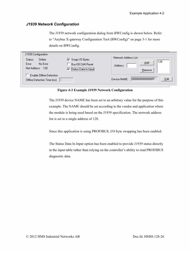
The J1939 network configuration dialog from BWConfig is shown below. Refer
to “Anybus X-gateway Configuration Tool (BWConfig)” on page 3-1 for more
details on BWConfig.
The J1939 device NAME has been set to an arbitrary value for the purpose of this
example. The NAME should be set according to the vendor and application where
the module is being used based on the J1939 specification. The network address
list is set to a single address of 128.
Since this application is using PROFIBUS, I/O byte swapping has been enabled.
The Status Data In Input option has been enabled to provide J1939 status directly
in the input table rather than relying on the controller’s ability to read PROFIBUS
diagnostic data.
Figure 4-3 Example J1939 Network Configuration
© 2012 HMS Industrial Networks AB Doc.Id. HMSI-128-26
Example Application 4-3
J1939 I/O Configuration
Input Data PointsThe input data points are responsible for determining where in the J1939 device
input table the J1939 data is to be placed. It is desirable to be able to address the 2
values in our example as individual words at the PROFIBUS master. Since the
values are packed into 3 bytes in the J1939 message, they need to be parsed out
into 2 16-bit words in the input table
This application will store up to 20 diagnostic entries in the diagnostic table for
the ECM at address 2. The diagnostic table will be requested from the ECM every
5 seconds.
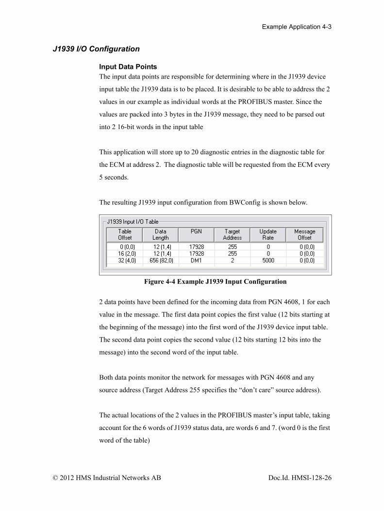
The resulting J1939 input configuration from BWConfig is shown below.
2 data points have been defined for the incoming data from PGN 4608, 1 for each
value in the message. The first data point copies the first value (12 bits starting at
the beginning of the message) into the first word of the J1939 device input table.
The second data point copies the second value (12 bits starting 12 bits into the
message) into the second word of the input table.
Both data points monitor the network for messages with PGN 4608 and any
source address (Target Address 255 specifies the “don’t care” source address).
The actual locations of the 2 values in the PROFIBUS master’s input table, taking
account for the 6 words of J1939 status data, are words 6 and 7. (word 0 is the first
word of the table)
Figure 4-4 Example J1939 Input Configuration
© 2012 HMS Industrial Networks AB Doc.Id. HMSI-128-26
Example Application 4-4
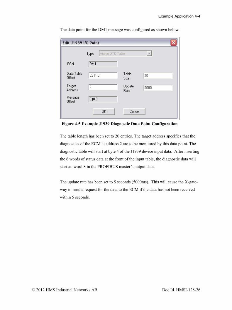
The data point for the DM1 message was configured as shown below.
The table length has been set to 20 entries. The target address specifies that the
diagnostics of the ECM at address 2 are to be monitored by this data point. The
diagnostic table will start at byte 4 of the J1939 device input data. After inserting
the 6 words of status data at the front of the input table, the diagnostic data will
start at word 8 in the PROFIBUS master’s output data.
The update rate has been set to 5 seconds (5000ms). This will cause the X-gate-
way to send a request for the data to the ECM if the data has not been received
within 5 seconds.
Figure 4-5 Example J1939 Diagnostic Data Point Configuration
© 2012 HMS Industrial Networks AB Doc.Id. HMSI-128-26

Example Application 4-5
Output Data PointsThe output data points determine what PGNs are going to be produced by the X-
gateway on J1939, and what the content of those PGN messages is going to be.
Since the example application only needs to produce 16 bits of data in a single
PGN message, the resulting configuration is quite simple. It is shown below.
The single data point specifies that 2 bytes of data from the beginning of the J1939
device output table is going to be copied into the first 2 bytes of the message. The
message will be transmitted with a PGN of 256 and a priority of 6 every 100ms.
The message will be broadcast (Target Address 255) so that it can be seen by
everyone on the network.
After accounting for the 4 bytes of command register, the data used for the PGN
256 message is located at word 2 of the PROFIBUS master’s output data. (the
output table starts at word 0)
Figure 4-6 Example J1939 Output Configuration
© 2012 HMS Industrial Networks AB Doc.Id. HMSI-128-26
Example Application 4-6
PROFIBUS Master Configuration
The I/O table sizes and layout for the X-gateway are defined in the PROFIBUS
master’s configuration tool using modules define in the X-gateway’s GSD file.
The I/O size defined by the PROFIBUW module configuration must exactly the
size defined by the J1939 I/O configuration in BWConfig.
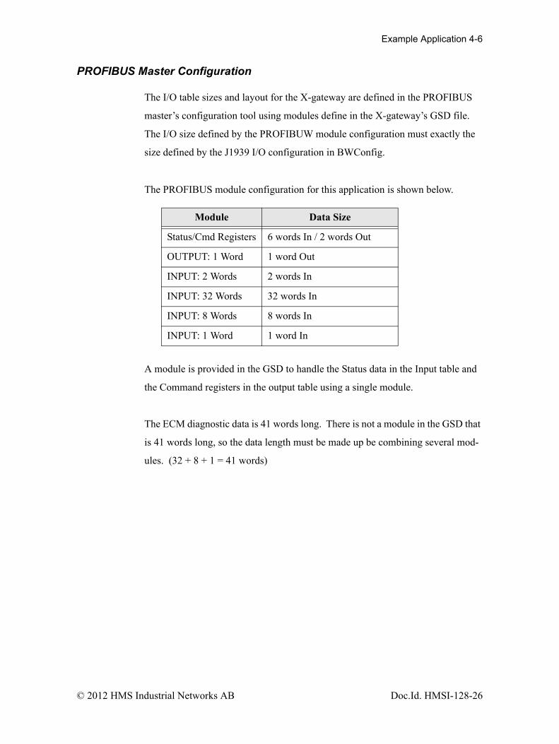
The PROFIBUS module configuration for this application is shown below.
A module is provided in the GSD to handle the Status data in the Input table and
the Command registers in the output table using a single module.
The ECM diagnostic data is 41 words long. There is not a module in the GSD that
is 41 words long, so the data length must be made up be combining several mod-
ules. (32 + 8 + 1 = 41 words)
Module Data Size
Status/Cmd Registers 6 words In / 2 words Out
OUTPUT: 1 Word 1 word Out
INPUT: 2 Words 2 words In
INPUT: 32 Words 32 words In
INPUT: 8 Words 8 words In
INPUT: 1 Word 1 word In
© 2012 HMS Industrial Networks AB Doc.Id. HMSI-128-26

Chapter 5 J1939 Interface 5-1
J1939 Interface
Address Management
The Anybus X-gateway address management is responsible for bringing the mod-
ule online on the J1939 network with a unique network address in accordance to
the J1939-81 specification. The address management will claim a configured
address, if possible, and protect it against lower priority contending address
claims. If a configured address is unable to be uniquely claimed, or is lost due to a
higher priority contending claim, the module will be taken offline.
This manual will not discuss the address management protocol in detail; readers
should reference the J1939-81 specification for complete details. The scope of this
section is to explain how the configuration of the address list affects address man-
agement.
Single Configured AddressIf a single address is configured in the address list, the module will attempt to
claim that address. If the configured address is successfully claimed, the module
will join the J1939 network using that address. If the address cannot be claimed,
the module remains offline.
Multiple Configured AddressesIf more than one address is configured in the address list, the module will attempt
to claim addresses in the order they appear in the list until it is either successful, or
it runs out of addresses. Once an address is successfully claimed, the module will
join the J1939 network using that address. If an address cannot be claimed, the
module moves to the next address in the list and attempts to claim that address. If
no addresses in the list can be claimed, the module remains offline.
© 2012 HMS Industrial Networks AB Doc.Id. HMSI-128-26

J1939 Interface 5-2
Address LossIf the module loses its current network address to a higher priority contending
address claim, it will cease all network activity using that address. If the address
list is configured with a single address, the module will remain offline after an
address loss. If the address list has multiple addresses, the module will attempt to
claim the next address on the list. If no addresses in the list can be successfully
claimed, the module will remain offline.
Invalid AddressesIf the address configured is invalid (outside of the range 0-253), the module will
remain offline and not attempt an address claim.
Request for Address ClaimedThe X-gateway will respond to a Request for the Address Claimed PGN
(0x00EE00) sent both destination specific and broadcast. The response is depen-
dent on the current address management state, and is discussed below.
• If the module has successfully claimed an address and is online, the response will be an Address Claimed message with the current address.
• If the module is offline because it has lost its address to a higher priority claim and cannot successfully claim another address, the response will be a Cannot Claim Address message.
• If the module is in the process of attempting to claim an address, it will not respond to the request.
• If the module is offline because it has not yet attempted to claim an address, or the configured address is invalid, it will not respond to the request.
Communications Methods
The J1939 network interface supports reception and transmission of the following
J1939 message types in accordance to the J1939-21 specification.
•PDU1 destination specific•PDU1 broadcast•PDU2 (broadcast)
© 2012 HMS Industrial Networks AB Doc.Id. HMSI-128-26

J1939 Interface 5-3
Message Transmission
Messages are transmitted on the J1939 network according to the J1939 output
configuration. Messages are assembled from data in the Output table and trans-
mitted on a cyclic time basis, or in response to a request for the associated PGN.
Data Point to Message RelationshipOutput data points with the same PGN and Target Address collectively define a
single message to be transmitted on the network.
Message AssemblyMessages are assembled according to the output data points configured for the
associated PGN and Target Address. Data is copied from the Output table to the
message buffer based on the sizes and offsets of all output data points configured
with the PGN and Target Address.
All bits in the message buffer that are not set from the Output table (ranges in the
buffer that are not referenced by output data points) are set to 1.
The message length is set according to the size of the data point with the largest
message offset. The length is rounded out to the nearest byte.
Note: Message length is strictly determined by the output data point configura-
tion for a given message. The X-gateway does not know the required data length
for all possible PGN's. The output data point configuration must provide a data
point that will specify the end of the message to ensure that the correct size mes-
sage is assembled.
© 2012 HMS Industrial Networks AB Doc.Id. HMSI-128-26

J1939 Interface 5-4
Automatic TransmissionMessages are transmitted automatically based on the Update Time parameter in
the output data points associated with the message. The smallest, non-zero Update
Time of all data points associated with the message will be used.
If the Update Time is configured as 0, no automatic transmission will occur for
the message. The only way that a message configured in this way will be transmit-
ted is if a request is received for the associated PGN.
Automatic transmission for a message will occur Update Time milliseconds after
the last transmission of the message, regardless of whether the last transmission
was automatic or a response to a request PGN.
© 2012 HMS Industrial Networks AB Doc.Id. HMSI-128-26
J1939 Interface 5-5
Handling Request PGNsRequests received that reference a PGN in an output data point will cause a mes-
sage transmission of that message. The message will be assembled and transmit-
ted immediately in response to the request, regardless of the timing of the
automatic transmission.
Requests received that reference a PGN not configured in an output data point will
cause a NAK response if the request was destination specific. Broadcast requests
for non-configured PGNs will be ignored.
Destination AddressesThe destination address used for message transmission is dependant on the associ-
ated output data point configuration or the request message, whichever caused the
transmission. The rules for destination addressing follow.
• If the message PGN is a PDU2 type, all PDU2 messages are broadcast by definition.
• If the transmission is automatic and the Target Address set to 255, the message will be broadcast.
• If the transmission is automatic and the Target Address is not 255, the message will be destination specific to the Target Address.
• If the transmission is due to a request and the request was destination spe-cific, the message will be destination specific to the source address of the request.
• If the transmission is due to a request and the request was broadcast, the message will be broadcast.
Message PriorityThe priority of the message being transmitted is set to the priority configured in
the Output Data Point. By specification, the default priority of J1939 messages is
6.
Important: Care should be taken when changing the priority of mes-
sages to a value other than 6 as it may affect the performance of other
traffic on the J1939 network.
© 2012 HMS Industrial Networks AB Doc.Id. HMSI-128-26

J1939 Interface 5-6
Receiving Messages
Handled MessagesThe following J1939 messages are handled by the X-gateway when they are
received from the network.
• Address Claimed messages are handled by address management. See “Address Management” on page 5-1.
• Request for Address Claimed messages are handled by address manage-ment. See “Address Management” on page 5-1.
• Request messages referencing PGNs configured in output data points trig-ger message transmission for the associated message. See “Message Transmission” on page 5-3.
• Messages with PGNs and source addresses matching configured input data points trigger an Input table update. See “Input Table Update” on page 5-6.
Input Table UpdateMessages received with a PGN and source address matching that configured for
an input data point will be parsed according to the configured data points.
Input data points are combined according to PGN and Target Address. All input
data points with matching PGN and Target Address are combined to define the
handling for a given message.
If the Target Address is configured as 255, all incoming messages with a match-
ing PGN will be parsed using the data point, regardless of source address. If the
Target Address is not 255, received messages must match both the PGN and
source address in order to be handled by the input data point. Received messages
are handled by all input data points that meet these rules; a given message may be
processed by more than one input data point.
If a received message passes an input data point’s matching test, the data from its
message buffer is copied to the Input table according to the data point configura-
tion. Data of the configured length is copied from the configured message buffer
offset to the configured Input table offset.
© 2012 HMS Industrial Networks AB Doc.Id. HMSI-128-26

J1939 Interface 5-7
Parameter Timeout IndicationParameter timeout indication has been provided to allow the PROFIBUS control-
ler to determine if a device on the J1939 network has gone inactive.
Input data points configured with a non-zero update rate will indicate a timeout
when the associated message is not received within the configured update rate.
The timeout indication is all bits in input table data for the input data point set to
1. This will effect all input data points associated with the PGN/Target Address.
The result appears as if a message was received which contained 0xFF for all data
bytes in the message.
Note: The timeout indication (all bits set to 1) will also be used for input data
points with non-zero update rates whenever an offline status is detected.
© 2012 HMS Industrial Networks AB Doc.Id. HMSI-128-26

J1939 Interface 5-8
Transport Protocol for Large Messages
The previous sections discussed message handling generically, ignoring message
sizes. Messages with buffer sizes of 8 bytes or less can be directly sent and
received on J1939. However, messages with buffer sizes greater than 8 bytes must
be fragmented, transmitted, and reassembled using the J1939 transport protocol.
This section will not discuss the details of the transport protocol, readers should
reference the J1939-21 specification; this document will provide a description of
when and how the transport protocol is used by the X-gateway.
Transmission of Large MessagesMessages larger than 8 bytes in length will be sent using transport protocol. If the
destination address is 255, the message will be broadcast using BAM (Broadcast
Announce Message) mechanisms. If the message is destination specific, a connec-
tion will be opened with the destination node and the message sent using RTS/
CTS (Request To Send/Clear To Send) mechanisms. For a complete discussion of
BAM and RTS/CTS refer to the J1939-21 specification.
Reception of Large MessagesThe X-gateway will receive large messages that are broadcast using BAM or sent
to the module using RTS/CTS. Once a complete message is received and reassem-
bled, it is processed generically as described in the previous sections.
LimitationsThe current implementation of the transport protocol in the X-gateway is limited
as described below.
• Only a single outgoing transport protocol session is active at a time, regardless of whether the message is transmitted using BAM or RTS/CTS. Large messages are queued for transmission and transmitted in the order in which they are queued.
• The module supports up to 35 concurrent incoming transport protocol ses-sions. The concurrent sessions may be any mixture of BAM and RTS/CTS sessions. Additional BAM sessions will be ignored and RTS connec-tion requests will be denied once the limit is reached.
© 2012 HMS Industrial Networks AB Doc.Id. HMSI-128-26

J1939 Interface 5-9
J1939 Diagnostic Messages
The DM1 (active diagnostics) and DM2 (previously active diagnostics) are the 2
most commonly used J1939 diagnostic messages. The X-gateway includes sup-
port for these 2 message types.
Using BWConfig, the user is able to configure an active or previously active diag-
nostic table (or both) for a given J1939 device. The X-gateway will update the
tables based on the contents of DM1 or DM2 messages produced on J1939 by the
device, and provide read access to the tables on PROFIBUS.
This section will describe how the diagnostic tables are handled. See “J1939
Diagnostic Tables” on page 3-14 for configuration details.
Diagnostic Table FormatThe active and previously active diagnostic tables have the same format. The for-
mat consists of a table header followed by a list of table entries.
Table HeaderThe table header is a 16-bit word and provides an indication of the number of
diagnostic entries that are currently in the table. It also contains the current J1939
lamp status information. The table header content is described below.
Bit Description
0-1 J1939 Protect lamp status.
2-3 J1939 Amber Warning lamp status.
4-5 J1939 Red Stop lamp status.
6-7 J1939 Malfunction lamp status.
8-14 Entry count. The current number of entries in the table.If the Update Rate is non-zero, the Entry count is set to 0xFF to indicate a timeout.
15 Table overflow indication.
Table 5-1 J1939 Diagnostic Table Header Content
© 2012 HMS Industrial Networks AB Doc.Id. HMSI-128-26

J1939 Interface 5-10
Table EntryEach entry in the table contains information for a single diagnostic (J1939 SPN/
FMI). Each table entry is 4 bytes with bit fields as described in the tables below.
The J1939 SPN value may be encoded differently in the diagnostic message
received from the ECU. Due to an early vagueness in the J1939-73 specification,
there is not a definite means to tell how the SPN is encoded. ECU’s that follow
the current specification will set the SPN Conversion Method flag to 0 and will
encode the SPN value in a specific way. ECU’s that follow the early specification
will set the Conversion Method flag to 1; however, there are 3 ways that the SPN
may be encoded in this case.
The X-gateway module, as of v2.03.01 provides the value of the Conversion
Method in the diagnostic table entries. If the Conversion Method is set to 1, the
user should refer to the ECU vendor to determine how the SPN is encoded.
The tables below illustrate how the SPN is stored in the diagnostic table entry for
each type of SPN encoding described in the J1939-73 specification.
SPN Conversion Method 0:
Word Byte Bits Description
0 0 0-2 J1939 SPN bits 16-18.
3-7 J1939 FMI.
1 0-6 Occurrence count.
7 SPN Conversion Method (set to 0)
1 2 0-7 J1939 SPN bits 0-7
3 0-7 J1939 SPN bits 8-15
Table 5-2 Diagnostic Table Entry Content for SPN Conversion Method 0
© 2012 HMS Industrial Networks AB Doc.Id. HMSI-128-26

J1939 Interface 5-11
SPN Conversion Method 1 - Encoding version 1 - The least significant bits with
the FMI and the upper 16 bits in Big Endian order.
SPN Conversion Method 1 - Encoding version 2 - The least significant bits with
the FMI and the upper 16 bits in Little Endian order.
Word Byte Bits Description
0 0 0-2 J1939 SPN bits 0-2
3-7 J1939 FMI.
1 0-6 Occurrence count.
7 SPN Conversion Method (set to 1)
1 2 0-7 J1939 SPN bits 11-18
3 0-7 J1939 SPN bits 3-10
Table 5-3 Diagnostic Table Entry Content for SPN Conversion Method 1, Version 1
Word Byte Bits Description
0 0 0-2 J1939 SPN bits 0-2
3-7 J1939 FMI.
1 0-6 Occurrence count.
7 SPN Conversion Method (set to 0)
1 2 0-7 J1939 SPN bits 3-10
3 0-7 J1939 SPN bits 11-18
Table 5-4 Diagnostic Table Entry Content for SPN Conversion Method 1, Version 2
© 2012 HMS Industrial Networks AB Doc.Id. HMSI-128-26
J1939 Interface 5-12
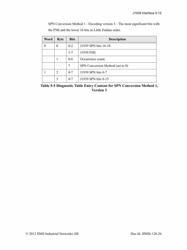
SPN Conversion Method 1 - Encoding version 3 - The most significant bits with
the FMI and the lower 16 bits in Little Endian order.
Word Byte Bits Description
0 0 0-2 J1939 SPN bits 16-18.
3-7 J1939 FMI.
1 0-6 Occurrence count.
7 SPN Conversion Method (set to 0)
1 2 0-7 J1939 SPN bits 0-7
3 0-7 J1939 SPN bits 8-15
Table 5-5 Diagnostic Table Entry Content for SPN Conversion Method 1, Version 3
© 2012 HMS Industrial Networks AB Doc.Id. HMSI-128-26

J1939 Interface 5-13
Bus-Off Reset Option
The bus-off reset option allows the X-gateway to be configured to attempt to
come back online after it has been knocked offline due to excessive CAN errors.
Option DisabledIf the bus-off reset option is disabled, the X-gateway will remain offline after a
bus-off condition is detected; it will not participate in any J1939 network activity.
The only way to bring the module back online is to power cycle the module.
Option EnabledIf the bus-off reset option is enabled, the X-gateway will reinitialize the CAN con-
troller after a bus-off condition is detected. Once the controller is reinitialized, the
module will attempt to go online and resume network activity on the J1939 net-
work.
WARNINGIt is suggested that the bus-off reset option be disabled for most applications.
Severe network problems can arise if the option is enabled and the X-gateway
module is the node that is causing the CAN errors.
Important: THIS OPTION SHOULD NEVER BE ENABLED
WHEN THE MODULE IS USED ON A CONTROL NETWORK OF
ANY KIND! IT SHOULD BE RESERVED FOR MONITORING
NETWORKS.
© 2012 HMS Industrial Networks AB Doc.Id. HMSI-128-26
J1939 Interface 5-14
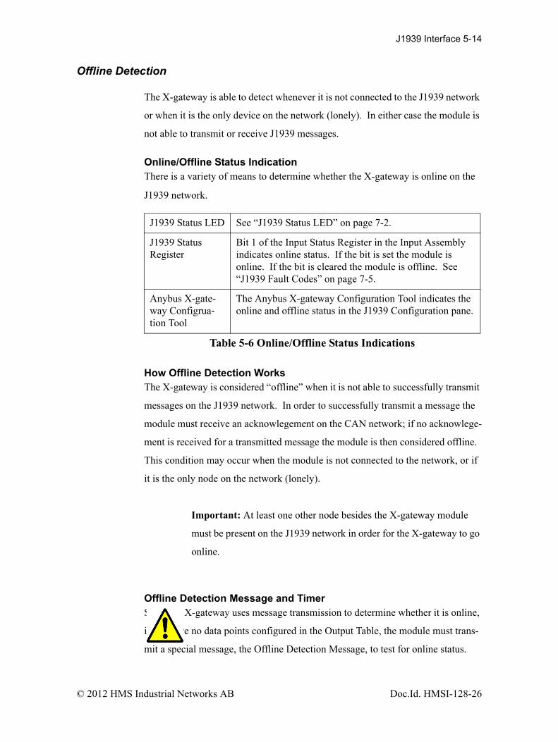
Offline Detection
The X-gateway is able to detect whenever it is not connected to the J1939 network
or when it is the only device on the network (lonely). In either case the module is
not able to transmit or receive J1939 messages.
Online/Offline Status IndicationThere is a variety of means to determine whether the X-gateway is online on the
J1939 network.
How Offline Detection WorksThe X-gateway is considered “offline” when it is not able to successfully transmit
messages on the J1939 network. In order to successfully transmit a message the
module must receive an acknowlegement on the CAN network; if no acknowlege-
ment is received for a transmitted message the module is then considered offline.
This condition may occur when the module is not connected to the network, or if
it is the only node on the network (lonely).
Important: At least one other node besides the X-gateway module
must be present on the J1939 network in order for the X-gateway to go
online.
Offline Detection Message and TimerSince the X-gateway uses message transmission to determine whether it is online,
if there are no data points configured in the Output Table, the module must trans-
mit a special message, the Offline Detection Message, to test for online status.
J1939 Status LED See “J1939 Status LED” on page 7-2.
J1939 Status Register
Bit 1 of the Input Status Register in the Input Assembly indicates online status. If the bit is set the module is online. If the bit is cleared the module is offline. See “J1939 Fault Codes” on page 7-5.
Anybus X-gate-way Configrua-tion Tool
The Anybus X-gateway Configuration Tool indicates the online and offline status in the J1939 Configuration pane.
Table 5-6 Online/Offline Status Indications
© 2012 HMS Industrial Networks AB Doc.Id. HMSI-128-26

J1939 Interface 5-15
The Offline Detection Message uses PGN 61184 (EF00h) with the source and
destination address both set to the address of the X-gateway.
The Offline Detection Message may be enabled or disabled in the configuration.
When the message is enabled, the Offline Detection Time determines how often
the Offline Detection Message will be sent. This effectively determines the time
within which an offline condition will be detected. If the application requies that
the offline status be detected quickly the time should be set to a smaller value; if
the application does not require quick detection the time may be set to a larger
value.
Note: The offline detection mechanism is always active regardless of whether the
X-gateway is in Run or Idle mode. The module will transmit Offline Detection
Messages when it is in Idle mode. This ensures that the online status being
reported is always correct.
Important: If periodic transmission of PGN 61184 could cause
adverse affects in the network application, make sure to disable the
Offline Detection in the configuration.
Important: The Offline Detection Time should be set as large as the
application will allow. Although setting the time to a small value will
provide quicker detection of an offline condition, there is a trade-off in
that the Offline Detection Message is being transmitted more often.
This trade-off could affect the performance of the X-gateway and of
the J1939 network overall.
© 2012 HMS Industrial Networks AB Doc.Id. HMSI-128-26

J1939 Interface 5-16
Offline Detection with Offline Detection Message DisabledWhen the Offline Detection Message feature in the configuration is disabled
offline detection will be performed on the messages transmitted by the output data
points. An offline condition will be detected whenever an output message is
transmitted. If the output data point transmission rate is large, an offline condition
that occurs between transmissions will be detected at the next transmission. If no
output data points are configured an offline condition will not be detected.
Offline Detection with Offline Detection Message EnabledWhen the Offline Detection Message feature in the configuration is enabled
offline detection will be performed on the messages transmitted by the output data
points as well as the Offline Detection Message. As described above, an offline
condition will be detected whenever an output message is transmitted. If the
Offline Detection Time is less than the output message transmission rate, the Out-
put Detection Message will be transmitted between output data point messages to
increase the rate at which an offline condition will be detected. If output data
point messages are transmitted at a faster rate than the Offline Detection Time, the
Offline Detection Message will not be transmitted.
© 2012 HMS Industrial Networks AB Doc.Id. HMSI-128-26

J1939 Interface 5-17
J1939 Baud Rate
The X-gateway is capable of supporting communication baud rates on the J1939
network of 250K and 500K baud. The correct baud rate must be configured
through the BWConfig Baud Rate option in the J1939 Configuration pane.
Important: The standard baud rate for J1939 is 250K baud. Do not
set the baud rate to 500K baud unless you are certain that all devices
on the network are communicating at 500K baud.
Important: Configuring the module with the incorrect baud rate may
cause other devices on the network to experience bus-off faults.
© 2012 HMS Industrial Networks AB Doc.Id. HMSI-128-26

Chapter 6 PROFIBUS Interface 6-1
PROFIBUS Interface
Network Communication
ProtocolThe Anybus PROFIBUS to J1939 X-gateway acts as a PROFIBUS-DP slave
node. It can be read from and written to by a PROFIBUS-DP master. The X-gate-
way will not initiate communication to other nodes on the PROFIBUS network; it
will only respond to incoming commands.
Details of the supported protocol features are listed below.
• PROFIBUS-DP EN 50 170 (DIN 19245).• Protocol version 1.10.• Baud rate range 9.6 Kbps - 12 Mbps.• Cyclic I/O data transmission.• Device diagnostic messages supported.
Physical Interface
Feature Specification
Media PROFIBUS bus line type A or B specified in EN50170.
Topology Master-Slave.
Connector 9-pin D-Subminiature female.
Cable Shielded twisted pair.
Isolation The bus is galvanically isolated from the X-gateway electronics.
Termination Switch selectable internal bus termination.
Table 6-1 PROFIBUS Physical Interface
© 2012 HMS Industrial Networks AB Doc.Id. HMSI-128-26

PROFIBUS Interface 6-2
Device Diagnostics
The X-gateway sends PROFIBUS device diagnostic messages to the PROFIBUS
master whenever there is a change in module status. The diagnostic data contains
information about the state of the module, the J1939 communications, and an indi-
cation of I/O data integrity. If the Status Data In Input option is set in the J1939
configuration, the information in the diagnostic message will also be included at
the front of the input table. The diagnostic data is presented in detail in “PROFI-
BUS Device Diagnostic Data” on page 7-8
Interaction with I/O Tables
I/O Table UpdatesThe PROFIBUS interface in the X-gateway accesses the I/O tables as requests
from the PROFIBUS master are processed; there is no buffering or timed updates
of the I/O within the module. Safeguards are in place to ensure data integrity by
prohibiting simultaneous access by the PROFIBUS and J1939 interfaces. There is
no synchronization between the 2 network interfaces.
When output data is received from the PROFIBUS master, the module will copy
the data to the Output table. The data is always placed at the beginning (offset 0)
of the Output table. This data is available to be read by the J1939 interface as soon
as it has been written.
When it is time to transmit input data to the PROFIBUS master, the module will
retrieve the data that is currently in the Input table. Data is always read from the
beginning (offset 0) of the Input table. The data will be what was placed there by
the last write to the Input table by the J1939 interface.
© 2012 HMS Industrial Networks AB Doc.Id. HMSI-128-26

PROFIBUS Interface 6-3
Data Endian-nessThe X-gateway transfers I/O data between PROFIBUS and J1939 without regard
to data content or format. Due to this, the user is responsible for making sure that
the devices on either network understand the format of the data.
J1939 is a little endian protocol; values are transmitted least significant byte first.
Hence, all data in the I/O tables is assumed to be stored as little endian by the
J1939 nodes.
Care should be taken to make sure that the PROFIBUS master handles input data
and transmits output data in a format usable by the target J1939 devices. Like-
wise, the master must be aware of the format of the data collected from the J1939
devices.
The I/O Byte Swap option will aid this issue by swapping the bytes on 16-bit
boundaries. However, the user is still responsible for knowing where in the I/O
tables J1939 data has been mapped. See “J1939 Network Configuration” on
page 3-6 for details on the I/O Byte Swap option.
© 2012 HMS Industrial Networks AB Doc.Id. HMSI-128-26

PROFIBUS Interface 6-4
Input Table OrganizationThe input data from the J1939 devices is in the input table in the format that is laid
out by the mapping defined by the input data points configured with BWConfig.
If the Status Data In Input option is not set, the J1939 data starts at the front of the
input table. If the Status Data In Input option is set, the J1939 data will be offset
by 12 bytes (6 words) in the input table, and the status data will be at the front of
the table.
The status data included in the input table conforms to the format defined below.
See the full details of the fields of this structure in “J1939 Status Data in the Input
Table” on page 7-6.
The GSD file for the X-gateway provides a module of the correct size for the sta-
tus data to allow for easy PROFIBUS configuration when this option is set.
Byte Offset
Description
0-1 X-gateway module status.
2-3 J1939 interface status
4-5 J1939 status code
6-7 J1939 CAN error counter
8-9 J1939 CAN bus-off counter
10-11 J1939 CAN receive overrun error counter
Table 6-2 J1939 Status Data Format
© 2012 HMS Industrial Networks AB Doc.Id. HMSI-128-26
PROFIBUS Interface 6-5
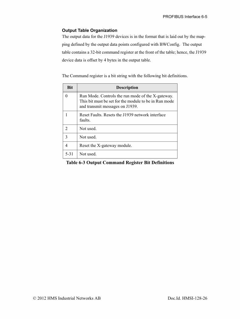
Output Table OrganizationThe output data for the J1939 devices is in the format that is laid out by the map-
ping defined by the output data points configured with BWConfig. The output
table contains a 32-bit command register at the front of the table; hence, the J1939
device data is offset by 4 bytes in the output table.
The Command register is a bit string with the following bit definitions.
Bit Description
0 Run Mode. Controls the run mode of the X-gateway.This bit must be set for the module to be in Run mode and transmit messages on J1939.
1 Reset Faults. Resets the J1939 network interface faults.
2 Not used.
3 Not used.
4 Reset the X-gateway module.
5-31 Not used.
Table 6-3 Output Command Register Bit Definitions
© 2012 HMS Industrial Networks AB Doc.Id. HMSI-128-26

PROFIBUS Interface 6-6
I/O Data Summary
The following diagram illustrates how the various components of the input data
are used to create the input data accessible from PROFIBUS.
Figure 6-1 Input Data Association - Status In Input Option Disabled
Figure 6-2 Input Data Association - Status In Input Option Enabled
© 2012 HMS Industrial Networks AB Doc.Id. HMSI-128-26

PROFIBUS Interface 6-7
The following diagram illustrates how the various components of the output data
are used to create the output data accessible from PROFIBUS.
Figure 6-3 Output Data Association
© 2012 HMS Industrial Networks AB Doc.Id. HMSI-128-26

Chapter 7 Status and Diagnostics 7-1
Status and Diagnostics
X-gateway LEDs
There is a group of LED indicators on the front of the X-gateway that is used to
annunciate the current status of the module and the network interfaces. The layout
of the LEDs is shown below.
X-gateway Status LED
Major unrecoverable faults are indicated by a series of green and red flashes. If
the X-gateway Status LED is flashing red and green for an extended period of
time, count the number of red and green flashes and call technical support.
Figure 7-1 X-gateway LEDs
State Summary Description
Flashing Green Idle Module is in Idle mode.
Solid Green Run Module is in Run mode.
Solid Orange Hardware Initialization
The LED will be in this state immedi-ately after power is applied.
Flashing Red/Green Error A major, unrecoverable fault has been detected.
Red, Green, OrangeAlternate Flashing
Self Test A self test of the module is in progress.
Table 7-1 X-gateway Status LED States
X-gateway Status
J1939 Status
Online
Diagnostic
OfflinePROFIBUS
© 2012 HMS Industrial Networks AB Doc.Id. HMSI-128-26

Status and Diagnostics 7-2
J1939 Status LED
State Summary Description
Flashing Green Initializing / Offline
The J1939 network interface is cur-rently being initialized and is waiting to come online. The module is not par-ticipating in J1939 traffic.
Solid Green Online A J1939 network address has been suc-cessfully claimed and the module is online and active.
Flashing Red/Green Online withFaults
The module is online and active on the J1939 network, but faults have been detected. Check the J1939 status code to determine the cause of the fault.
Solid Red Offline The module is not participating in the J1939 network.
Flashing Red Offline withFaults
The module is not participating in the J1939 network and faults have been detected. Check the J1939 status code to determine the cause of the fault.
Table 7-2 J1939 Status LED States
© 2012 HMS Industrial Networks AB Doc.Id. HMSI-128-26

Status and Diagnostics 7-3
PROFIBUS Online LED
PROFIBUS Offline LED
PROFIBUS Diagnostic LED
State Summary Description
Off Offline, or no module power
The X-gateway is either not powered, or not online on PROFIBUS.
Solid Green Online The X-gateway is online on the PRO-FIBUS network.
Table 7-3 PROFIBUS Online LED States
State Summary Description
Off Online, or no module power
The X-gateway is either not powered or is online on PROFIBUS.
Solid Red Offline The X-gateway is powered up, but is not participating in PROFIBUS activ-ity.
Table 7-4 PROFIBUS Offline LED States
State Summary Description
Off Normal No diagnostics are present.
Flashing Red at 1Hz
Configura-tion error
The input and/or output length set in module configuration does not match the value(s) set during network config-uration.
Flashing Red at 4Hz
Hardware error
An error occurred while initializing the PROFIBUS ASIC.
Table 7-5 PROFIBUS Diagnostic LED States
© 2012 HMS Industrial Networks AB Doc.Id. HMSI-128-26

Status and Diagnostics 7-4
J1939 Status Codes
The status codes for the J1939 interface are displayed by the Anybus X-gateway
Configuration Tool in the network configuration pane associated with the J1939
network. There are 2 status codes: a general status, and a J1939 fault status. The
general status is displayed as a textual status. The J1939 fault status codes is a bit
string, so the values are displayed in hexadecimal format to make them easier to
decipher.
© 2012 HMS Industrial Networks AB Doc.Id. HMSI-128-26

Status and Diagnostics 7-5
J1939 General Status
J1939 Fault Codes
Value Description
Initializing The J1939 network interface is initializing.
Offline The module is not participating in J1939 network activity.
Online The module is online and participating in J1939 network activ-ity.
Table 7-6 J1939 General Status Values
Bit Description
0 The address claim has failed. The Anybus X-gateway was unable to claim a unique J1939 network address and join network activity.
1 The CAN error counter has exceeded its warning limits at least one time since bootup or the last fault reset.
2 The CAN controller has reported a bus-off condition at least one time since bootup or the last fault reset.
3 A CAN receive overrun condition was detected at least one time since bootup or the last fault reset.
4 A J1939 transport protocol error has occurred at least one time since bootup or the last fault reset.
5 A receive message queue has overflowed at least one time since bootup or the last fault reset.
6 A transmit message queue has overflowed at least one time since bootup or the last fault reset.
7-15 Not used.
Table 7-7 J1939 Fault Code Bit Definitions
© 2012 HMS Industrial Networks AB Doc.Id. HMSI-128-26

Status and Diagnostics 7-6
J1939 Status Data in the Input Table
If the Status Data In Input option is set in the configuration, the J1939 status data
will be included at the front of the input table. The status data is 12 bytes long on
contains the following information.
ByteOffset
Sizein Bytes
Data Type Name Description
0 2 16-bit bit string
Module Status The current status of the module. See the bit definitions below.
2 2 UINT J1939 Interface Status
The current status of the J1939 inter-face. The following values are defined: 0x8000 Offline 0x8001 Online 0x8002 Initializing
4 2 16-bit bit string
J1939 Interface Faults
The current fault status of the J1939 interface. See the bit definitions in Table 7-7 Above.
6 2 UINT CAN Error Coun-ter
The number of CAN errors that have been accumulated. This counter is reset by the fault reset command bit.
8 2 UINT CAN Bus-Off Counter
The number of CAN bus-off errors that have occurred. This counter is reset by the fault reset command bit.
10 2 UINT CAN Overrun Counter
The number of CAN receive overrun errors that have occurred. This counter is reset by the fault reset command bit.
Table 7-8 J1939 Status Data Format
© 2012 HMS Industrial Networks AB Doc.Id. HMSI-128-26

Status and Diagnostics 7-7
The Module Status word in the Status data is a bit string with the following bit
definitions.
Bit Description
0 Run/IdleBit set indicates module is in Run mode.
1 J1939 OnlineBit set indicates module is online and active on J1939 network.
2 J1939 FaultBit set indicates that there is a fault on the J1939 net-work interface. See the value J1939 faults word for details.
3 PROFIBUS I/O Size Error.Bit set indicates a mismatch in I/O sizes between the X-gateway configuration and the PROFIBUS master configuration.
This bit is only used in the PROFIBUS Diagnostic data; it is not used in the Status Data in the input table.
4-15 Not used.
Table 7-9 Module Status Word Bit Definitions
© 2012 HMS Industrial Networks AB Doc.Id. HMSI-128-26

Status and Diagnostics 7-8
PROFIBUS Device Diagnostic Data
A PROFIBUS Diagnostic message is sent to the PROFIBUS master whenever
there is a change in module status. The diagnostic data can be used by the master
to determine the current status of the module, as well as a measure of I/O data
integrity.
Diagnostic Data FormatThe format of the PROFIBUS diagnostic data is the same as the status data in the
input table described above. Note that this data appears after the 6 byte header in
the PROFIBUS diagnostic message.
Static Diagnostic Control BitThe X-gateway makes use of the Static bit in the diagnostic control byte to notify
the PROFIBUS master that the I/O data integrity is in question. If the Static bit is
set, it is suggested that the PROFIBUS master ignore the input data and stop
updating the output data.
The Static bit is set in the diagnostic control byte if the X-gateway is not online on
the J1939 network.
© 2012 HMS Industrial Networks AB Doc.Id. HMSI-128-26

Chapter 8 Specifications 8-1
Specifications
Environmental Specifications
TemperatureOperating: 0 to 70 degrees Celsius
Non-Operating: -25 to 85 degrees Celsius
EMC Directive Compliance
This product is tested to meet the Council Directive 89/336/EC Electromagnetic
Compatibility (EMC) by applying the following standards, in whole or in part,
documented in a technical construction file:
• EN50081-2-EMC Generic Emission Standard, Part 2 - Industrial Envi-ronment
• EN50082-2-EMC Generic Immunity Standard, Part 2 - Industrial Envi-ronment
This product is intended for use in an industrial environment.
Electrical Specifications
DC PowerOperating voltage: 12-30v DC.
Current Requirements: 105-110 mA at 24 VDC.
© 2012 HMS Industrial Networks AB Doc.Id. HMSI-128-26
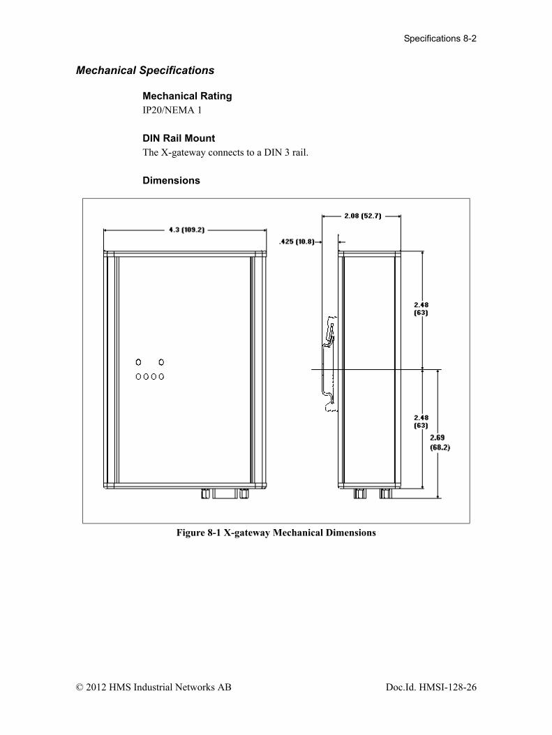
Specifications 8-2
Mechanical Specifications
Mechanical RatingIP20/NEMA 1
DIN Rail MountThe X-gateway connects to a DIN 3 rail.
Dimensions
Figure 8-1 X-gateway Mechanical Dimensions
© 2012 HMS Industrial Networks AB Doc.Id. HMSI-128-26

Specifications 8-3
I/O Data Sizes
•Maximum 244 bytes input including the status data if the Status In Input option is enabled.
•Maximum 244 bytes output including the command register.
•Combined Input and Output size must not be more than 400 bytes.
•200 total J1939 data points maximum (input plus output)
•Up to 120 different PGN’s may be monitored by input data points
•Up to 100 different PGN’s may be transmitted by output data points
J1939 Specifications
Message TypesSupports transmission and reception of the following message types:
•PDU1 destination specific•PDU1 broadcast •PDU2
AddressingClaims and protects a single configurable address.
Self-configurable using a list of addresses.
Transport Protocol SessionsSupport of J1939 transport protocol for large messages with the following limita-
tions:
•Single outgoing session (either BAM or RTS/CTS).•35 concurrent incoming sessions (any mixture of BAM and RTS/CTS).
© 2012 HMS Industrial Networks AB Doc.Id. HMSI-128-26

Chapter 9 Connectors 9-1
Connectors
Power
Use Phoenix connector part number MSTB 2,5/2-ST-5,08 ABGY
Pin Connection
1 24 VDC +
2 24 VDC Common
Table 9-1 Power Connector Pin Definitions
© 2012 HMS Industrial Networks AB Doc.Id. HMSI-128-26

Connectors 9-2
J1939
Use Phoenix connector part number MSTB 2,5/5-ST-5,08-ABGYAU.
Note: The 24VDC connections on the J1939 and Power connectors are physically
connected internally. The module may be powered from either set of pins.
Pin Signal
1 24 VDC Common
2 CAN Low
3 Shield
4 CAN High
5 24 VDC +
Table 9-2 J1939 Connector Pin Definitions
© 2012 HMS Industrial Networks AB Doc.Id. HMSI-128-26

Connectors 9-3
PROFIBUS
Pin Connection
1 Not used
2 Not used
3 B-Line
4 RTS
5 GND Bus
6 +5 V Bus
7 Not used
8 A-Line
9 Not used
Table 9-3 PROFIBUS Connector Pin Definitions
© 2012 HMS Industrial Networks AB Doc.Id. HMSI-128-26
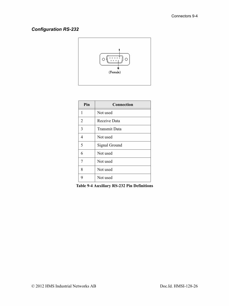
Connectors 9-4
Configuration RS-232
Pin Connection
1 Not used
2 Receive Data
3 Transmit Data
4 Not used
5 Signal Ground
6 Not used
7 Not used
8 Not used
9 Not used
Table 9-4 Auxiliary RS-232 Pin Definitions
© 2012 HMS Industrial Networks AB Doc.Id. HMSI-128-26
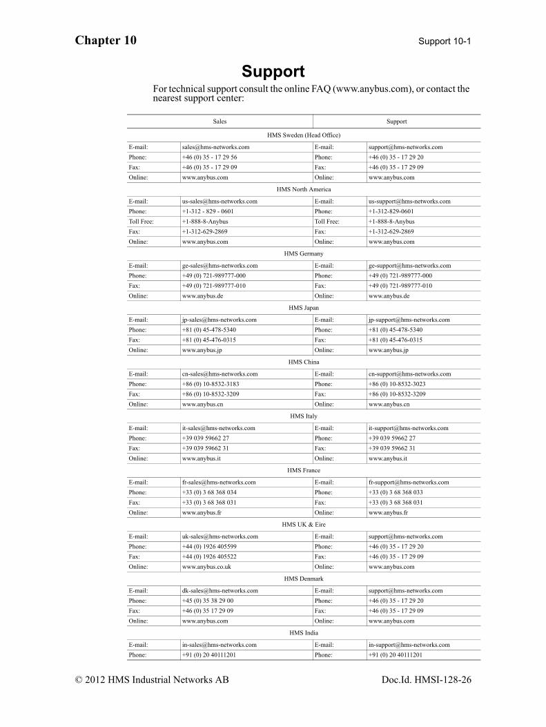
Chapter 10 Support 10-1
SupportFor technical support consult the online FAQ (www.anybus.com), or contact the nearest support center:
Sales Support
HMS Sweden (Head Office)
E-mail: [email protected] E-mail: [email protected]
Phone: +46 (0) 35 - 17 29 56 Phone: +46 (0) 35 - 17 29 20
Fax: +46 (0) 35 - 17 29 09 Fax: +46 (0) 35 - 17 29 09
Online: www.anybus.com Online: www.anybus.com
HMS North America
E-mail: [email protected] E-mail: [email protected]
Phone: +1-312 - 829 - 0601 Phone: +1-312-829-0601
Toll Free: +1-888-8-Anybus Toll Free: +1-888-8-Anybus
Fax: +1-312-629-2869 Fax: +1-312-629-2869
Online: www.anybus.com Online: www.anybus.com
HMS Germany
E-mail: [email protected] E-mail: [email protected]
Phone: +49 (0) 721-989777-000 Phone: +49 (0) 721-989777-000
Fax: +49 (0) 721-989777-010 Fax: +49 (0) 721-989777-010
Online: www.anybus.de Online: www.anybus.de
HMS Japan
E-mail: [email protected] E-mail: [email protected]
Phone: +81 (0) 45-478-5340 Phone: +81 (0) 45-478-5340
Fax: +81 (0) 45-476-0315 Fax: +81 (0) 45-476-0315
Online: www.anybus.jp Online: www.anybus.jp
HMS China
E-mail: [email protected] E-mail: [email protected]
Phone: +86 (0) 10-8532-3183 Phone: +86 (0) 10-8532-3023
Fax: +86 (0) 10-8532-3209 Fax: +86 (0) 10-8532-3209
Online: www.anybus.cn Online: www.anybus.cn
HMS Italy
E-mail: [email protected] E-mail: [email protected]
Phone: +39 039 59662 27 Phone: +39 039 59662 27
Fax: +39 039 59662 31 Fax: +39 039 59662 31
Online: www.anybus.it Online: www.anybus.it
HMS France
E-mail: [email protected] E-mail: [email protected]
Phone: +33 (0) 3 68 368 034 Phone: +33 (0) 3 68 368 033
Fax: +33 (0) 3 68 368 031 Fax: +33 (0) 3 68 368 031
Online: www.anybus.fr Online: www.anybus.fr
HMS UK & Eire
E-mail: [email protected] E-mail: [email protected]
Phone: +44 (0) 1926 405599 Phone: +46 (0) 35 - 17 29 20
Fax: +44 (0) 1926 405522 Fax: +46 (0) 35 - 17 29 09
Online: www.anybus.co.uk Online: www.anybus.com
HMS Denmark
E-mail: [email protected] E-mail: [email protected]
Phone: +45 (0) 35 38 29 00 Phone: +46 (0) 35 - 17 29 20
Fax: +46 (0) 35 17 29 09 Fax: +46 (0) 35 - 17 29 09
Online: www.anybus.com Online: www.anybus.com
HMS India
E-mail: [email protected] E-mail: [email protected]
Phone: +91 (0) 20 40111201 Phone: +91 (0) 20 40111201
© 2012 HMS Industrial Networks AB Doc.Id. HMSI-128-26

Support 10-2
Fax: +91 (0) 20 40111105 Fax: +91 (0) 20 40111105
Online: www.anybus.com Online: www.anybus.com
Sales Support
© 2012 HMS Industrial Networks AB Doc.Id. HMSI-128-26