anu cooling systems karl williams fermilab accelerator division cd-2/3a doe review of no a october...
TRANSCRIPT

ANU Cooling Systems
Karl WilliamsFermilab Accelerator Division
CD-2/3a DOE Review of NOAOctober 23-25, 2007

October 23-25, 2007 CD-2/3a DOE Review Karl Williams, ANU Cooling Systems 2
Overview
• Overall Scope• Recycler
– Scope– Technical
• Main Injector– Scope– Technical
• NuMI– Scope– Technical
• Associated Cooling Pond Loads• Costs• Risk and Mitigations• Review of CDR Recommendation

October 23-25, 2007 CD-2/3a DOE Review Karl Williams, ANU Cooling Systems 3
ANU Cooling Systems Scope
• All cooling systems are intertwined with each of the machines– For these tasks, no clear way to delineate
• Either by machine supported
• Or by system boundaries
– Addressed in ANU by machine supported

October 23-25, 2007 CD-2/3a DOE Review Karl Williams, ANU Cooling Systems 4
ANU Cooling Systems Scope
• Recycler– WBS 1.0.1.1.4, 2.0.1.1.4
• Main Injector– WBS 1.0.2.1.4, 1.0.2.2.1.3, 2.0.2.2.4
• NuMI– WBS 1.0.3.4, 2.0.3.4
• Associated Cooling Pond Loads– Addressed within the other tasks
• Manager for all of these systems

October 23-25, 2007 CD-2/3a DOE Review Karl Williams, ANU Cooling Systems 5
ANU Cooling Systems Scope
Progress since Director’s Review, June 2007• Reduced estimates for most NuMI Cooling Systems
– Installation of new air handling and dehumidification equipment at MI-65 and Target Hall by FESS
– Better definition of expected needs for NuMI Cooling Systems
– Both items reduced expected loads on NuMI Chilled Water and LCW Systems, simplifying needs for system upgrades
• MI and RR requirements remain virtually unchanged

October 23-25, 2007 CD-2/3a DOE Review Karl Williams, ANU Cooling Systems 6
Recycler Scope
Recycler
Injection Line and MI-14 Service Building
Abort Line and MI-39 Service Building
RF Cavities
Extraction Line
MI-8 Pump Room

October 23-25, 2007 CD-2/3a DOE Review Karl Williams, ANU Cooling Systems 7
Recycler Modifications
• Injection Line & MI-14 Service Building– Beam line magnets– Flourinert skids for kickers– Power supplies in MI-14– Estimated additional 65kW, 50gpm load to MI
Global LCW System
• Extraction Line & MI-30 Service Building– Beam line magnets– Flourinert skids for kickers– Power supplies in MI-30– Estimated additional 76kW, 60gpm load to MI
Global LCW System
October 23-25, 2007 CD-2/3a DOE Review Karl Williams, ANU Cooling Systems 8
Recycler Modifications (cont.)
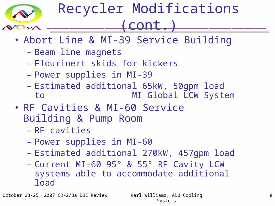
• Abort Line & MI-39 Service Building– Beam line magnets– Flourinert skids for kickers– Power supplies in MI-39– Estimated additional 65kW, 50gpm load to
MI Global LCW System
• RF Cavities & MI-60 Service Building & Pump Room– RF cavities– Power supplies in MI-60– Estimated additional 270kW, 457gpm load– Current MI-60 95° & 55° RF Cavity LCW systems
able to accommodate additional load

October 23-25, 2007 CD-2/3a DOE Review Karl Williams, ANU Cooling Systems 9
Recycler Modifications (cont.)
• MI-8 Pump Room Outfitting– Q-100 region LCW already near capacity
– Additional heat and hydraulic loads of Injection Line and MI-14 may mandate addition of outfitting of MI-8 Pump Room
– Originally planned in initial MI LCW Systems• Dedicated room in MI-8 already exists
• Includes piping to PV-9 Pond Vault, electrical service w/ MCU’s
– Biggest hurdle: PV-9 Pond Water lines also connected to MI-62 for NuMI LCW, which are already operating at capacity
October 23-25, 2007 CD-2/3a DOE Review Karl Williams, ANU Cooling Systems 10
Recycler Modifications (cont.)
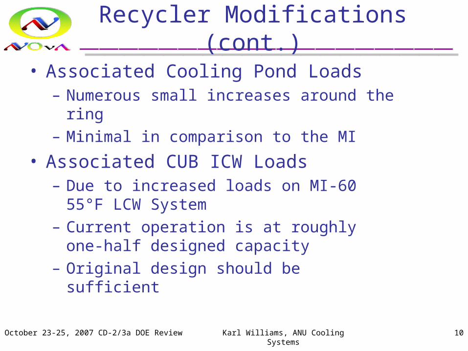
• Associated Cooling Pond Loads– Numerous small increases around the ring
– Minimal in comparison to the MI
• Associated CUB ICW Loads– Due to increased loads on MI-60 55°F LCW
System
– Current operation is at roughly one-half designed capacity
– Original design should be sufficient

October 23-25, 2007 CD-2/3a DOE Review Karl Williams, ANU Cooling Systems 11
Recycler Modifications (cont.)
Recycler LCW Loads due to ANU Modifications
System ComponentAnticipated Flow, gpm
Anticipated Load, kW
Affected System
Injection Line & MI-14 Service Building -50 + 65 Global MI LCW
Extraction Line & MI-30 Service Building -60 + 76 Global MI LCW
Abort Line & MI-39 Service Building - 50 + 65 Global MI LCW
MI-8 Pump Room + 400 - 600 Global MI LCW
Total +260 -394
October 23-25, 2007 CD-2/3a DOE Review Karl Williams, ANU Cooling Systems 12
Recycler Modifications (cont.)
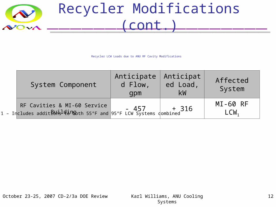
Recycler LCW Loads due to ANU RF Cavity Modifications
System ComponentAnticipated Flow, gpm
Anticipated Load, kW
Affected System
RF Cavities & MI-60 Service Building - 457 + 316 MI-60 RF LCW1
1 – Includes additions to both 55°F and 95°F LCW Systems combined

October 23-25, 2007 CD-2/3a DOE Review Karl Williams, ANU Cooling Systems 13
Main Injector Scope
Main Injector
General:Minor Magnet/Component ChangesGlobal Heat Load Increase (approx. 25%)Associated Increases to Cooling Ponds
RF Cavities
October 23-25, 2007 CD-2/3a DOE Review Karl Williams, ANU Cooling Systems 14
Main Injector Modifications
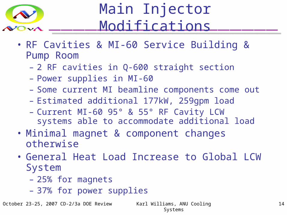
• RF Cavities & MI-60 Service Building & Pump Room– 2 RF cavities in Q-600 straight section– Power supplies in MI-60– Some current MI beamline components come out– Estimated additional 177kW, 259gpm load – Current MI-60 95° & 55° RF Cavity LCW systems able
to accommodate additional load
• Minimal magnet & component changes otherwise• General Heat Load Increase to Global LCW System
– 25% for magnets– 37% for power supplies

October 23-25, 2007 CD-2/3a DOE Review Karl Williams, ANU Cooling Systems 15
Main Injector Modifications (cont.)
• Associated Cooling Pond Loads– Approximately 25 to 30% increase in heat loads to ponds
– Primarily due to MI cycle changes, and that increased heat load into the MI Global LCW System
– Numerous additions and subtractions otherwise• From both RR and NuMI
• Minimal in comparison to the MI loads
• Associated CUB ICW Loads– Due to increased loads on MI-60 55°F LCW System
– Current operation is at roughly one-half designed capacity
– Original design should be sufficient

October 23-25, 2007 CD-2/3a DOE Review Karl Williams, ANU Cooling Systems 16
Main Injector Modifications (cont.)
Main Injector LCW Loads due to Global ANU Power Increase1
System ComponentCurrent Load,
kWScaling Factor
Anticipated Load, kW
LCW Pumps 496 1.0 496
Magnets 6110 1.272 7760
Power Supplies 984 1.3753 1353
Totals 7590 9599
1 - Assumes Global LCW System flows are maintained at current levels2 - Dave Harding 3 - Dan Wolff

October 23-25, 2007 CD-2/3a DOE Review Karl Williams, ANU Cooling Systems 17
Main Injector Modifications (cont.)
Main Injector LCW Loads due to ANU RF Cavity Modifications
System ComponentAnticipated Flow, gpm
Anticipated Load, kW
Affected System
RF Cavities & MI-60 Service Building - 259 + 177 MI-60 RF LCW1
1 – Includes additions to both 55°F and 95°F LCW Systems combined

October 23-25, 2007 CD-2/3a DOE Review Karl Williams, ANU Cooling Systems 18
NuMI Scope
NuMI
Absorber HallDecay Pipe Downstream RAWHadron Absorber RAW & IntermediateNuMI Sump Water
MI-62 Service BuildingNuMI LCW
MI-65 & Target HallTarget RAWHorn 1 & 2 RAWDecay Pipe Upstream RAW
CUBICW for MI-65
NuMI Extraction LineMI Global LCW
October 23-25, 2007 CD-2/3a DOE Review Karl Williams, ANU Cooling Systems 19
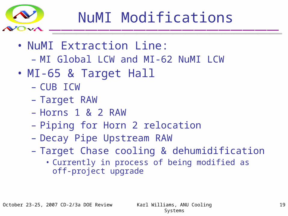
NuMI Modifications
• NuMI Extraction Line:– MI Global LCW and MI-62 NuMI LCW
• MI-65 & Target Hall– CUB ICW– Target RAW– Horns 1 & 2 RAW– Piping for Horn 2 relocation– Decay Pipe Upstream RAW– Target Chase cooling & dehumidification
• Currently in process of being modified as off-project upgrade

October 23-25, 2007 CD-2/3a DOE Review Karl Williams, ANU Cooling Systems 20
NuMI Modifications (cont.)
• Absorber Hall– Decay Pipe Downstream RAW– Hadron Absorber RAW & Intermediate– NuMI Sump Water
• Associated Cooling Pond Loads– Minimal increase, if any, at MI-62
• Associated CUB ICW Loads– Due to additional MI-65 loads– Original design should be sufficient
October 23-25, 2007 CD-2/3a DOE Review Karl Williams, ANU Cooling Systems 21
NuMI Modifications (cont.)
• NuMI Modifications – Planned Upgrades:– All systems will receive upgrades to instrumentation
– Some will also receive upgrades to pumps, heat exchangers, misc. components
– BoE’s list costs accordingly
October 23-25, 2007 CD-2/3a DOE Review Karl Williams, ANU Cooling Systems 22
ANU Cooling Systems
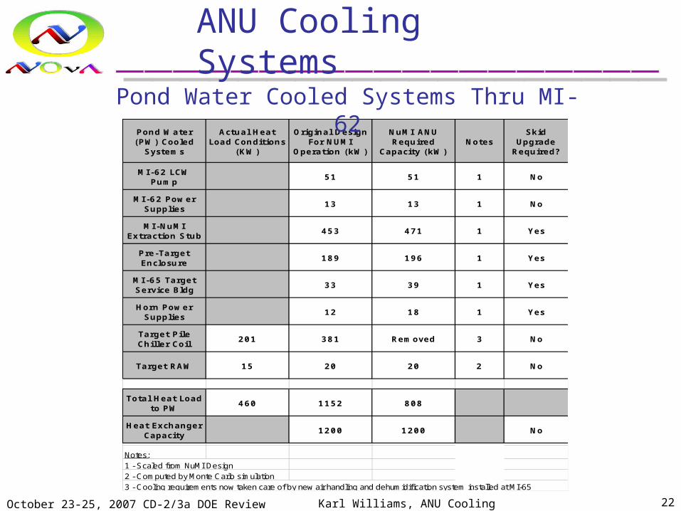
Pond Water (PW) Cooled
Systems
Actual Heat Load Conditions
(KW)
Original Design For NUMI
Operation (kW)
NuMI ANU Required
Capacity (kW)Notes
Skid Upgrade
Required?
MI -62 LCW Pump
51 51 1 No
MI-62 Power Supplies
13 13 1 No
MI-NuMI Extraction Stub
453 471 1 Yes
Pre-Target Enclosure
189 196 1 Yes
MI -65 Target Service Bldg
33 39 1 Yes
Horn Power Supplies
12 18 1 Yes
Target Pile Chiller Coil
201 381 Removed 3 No
Target RAW 15 20 20 2 No
Total Heat Load to PW
460 1152 808
Heat Exchanger Capacity
1200 1200 No
Notes:1 - Scaled from NuMI Design 2 - Computed by Monte Carlo simulation3 - Cooling requirements now taken care of by new air handling and dehumidification system installed at MI-65
Pond Water Cooled Systems Thru MI-62

October 23-25, 2007 CD-2/3a DOE Review Karl Williams, ANU Cooling Systems 23
ANU Cooling Systems
Secondary Chilled Water
(SCHW) System
Actual Heat Load Conditions
(KW)
Original Maximum
Design Capacity (KW)
NuMI ANU Required
Capacity (kW)Notes
Skid Upgrade
Required ?
Horn 1 RAW 30 72 90 1, 4 Yes
Horn 2 RAW 10 72 55 1, 4 Yes
Decay Pipe RAW (Upper)
2 79 138 1, 6 No
FCU-T-1 60 60 (60) 3, 5 Removed
Target Pile Chiller SCHW
HX28 28 (28) 3, 5 Removed
New Target Pile AHU coils (Chase Air Cooling)
(125) 2, 5 Removed
Total Heat Load to PW
130 239 283
Heat Exchanger Capacity
315 315 No
Notes:1 - Computed by Monte Carlo simulation2 - New requirements3 - Unchanged requirements4 - Ejector Pump upgrade required
5 - Cooling requirements now taken care of by new air handling and dehumidification system installed at MI-65
6 - In actual running conditions, there appears to be significant heat loss to surrounding rock, which was not included in original modeling
Secondary Chilled Water Cooled Systems at MI-65

October 23-25, 2007 CD-2/3a DOE Review Karl Williams, ANU Cooling Systems 24
ANU Cooling Systems
Ground Water (GW) Cooled
Systems
Original Design For NUMI
Operation (kW)
NuMI ANU Required
Capacity (kW)Notes
MINOS Ground Water (GW) Heat Exchanger
Maximum Heat Load Capacity (kW)
Decay Pipe RAW (Lower)
82 116 1 82
Intermediate RAW
211 105 1 212
Total Heat Load to GW
293 221 294
MINOS Absorber RAW Skid Heat Exchanger
Maximum Heat Load Capacity (KW)
Absorber RAW (Included in Intermediate RAW Values)
154 154 2 142
Notes:
1 - Scaled from Low Energy Target configuration2 - Computed by Monte Carlo simulation
NuMI Ground Water Cooled Systems at MINOS Absorber Area
October 23-25, 2007 CD-2/3a DOE Review Karl Williams, ANU Cooling Systems 25
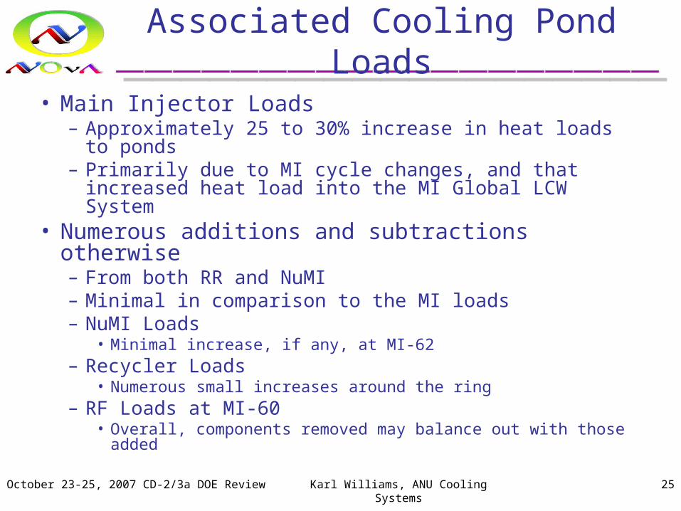
Associated Cooling Pond Loads
• Main Injector Loads– Approximately 25 to 30% increase in heat loads to ponds– Primarily due to MI cycle changes, and that increased heat
load into the MI Global LCW System• Numerous additions and subtractions otherwise
– From both RR and NuMI– Minimal in comparison to the MI loads– NuMI Loads
• Minimal increase, if any, at MI-62– Recycler Loads
• Numerous small increases around the ring– RF Loads at MI-60
• Overall, components removed may balance out with those added

October 23-25, 2007 CD-2/3a DOE Review Karl Williams, ANU Cooling Systems 26
Associated Cooling Pond Loads (cont.)
• Pond Water Loading Studies– Performed by S. Krstulovich, November 2006
– Computer model, normalized to our actual operational conditions
– Indicate an even 25% global increase in pond heat loads will increase operational temps by about 1°F
– Modeling may easily be repeated as requirements become better defined and understood
• Conclusion: – Current MI Cooling Ponds are probably sufficient

October 23-25, 2007 CD-2/3a DOE Review Karl Williams, ANU Cooling Systems 27
Associated Cooling Pond Loads (cont.)
• Pond Water Loading Studies – Conclusion Expounded– Currently, there are 6 to 8 weeks of the summer where the
ponds warm to the extent that they cannot cool the MI LCW systems sufficiently for them to maintain a 90degF operational setpoint. During these periods, the ponds warm to around 90degF themselves. When this happens, the 3-way temperature control valves wind up sitting 100% open, calling for even more cooling than the pond waters can provide, and the LCW Supply temperatures slowly climb to the 95 to 100F range.
– It is suspected that the increase in heat loads could extend this period to a length of 10 to 12 weeks, although more exact analysis is not currently available.
October 23-25, 2007 CD-2/3a DOE Review Karl Williams, ANU Cooling Systems 28
Associated Cooling Pond Loads (cont.)
• Pond Water Loading Studies - References:– NOVA Document 1573-v3, MI LCW and Pond Water
Temperature Studies, Karlton E. Williams
– NOVA Document 1895-v1, MI Pond Water Modeling for ANU Increased Heat Loads, Stephen F. Krstulovich

October 23-25, 2007 CD-2/3a DOE Review Karl Williams, ANU Cooling Systems 29
Cost Overview Recycler & MI Cooling Systems (Fully Burdened FY07 $)
WBS Name M&S Labor TotalM&S Cont
%Labor Cont
%Total
Cont %
Recycler Cooling System $287 $941 $1,228 57% 43% 46% $1,794
1.0.1.1.4Recycler Cooling System Planning, Engineering & Design $0 $347 $347 0% 40% 40% $486
2.0.1.1.4 Recycler Cooling System Construction $287 $594 $881 57% 45% 49% $1,308
Main Injector Cooling System $6 $140 $145 24% 21% 21% $176
1.0.2.1.4MI Cooling System Planning, Engineering & Design $0 $42 $42 0% 20% 20% $50
1.0.2.2.1.3MI RF Cavity Cooling System Planning, Engineering & Design $0 $49 $49 0% 20% 20% $59
2.0.2.2.4Main Injector Cooling System Construction $6 $48 $54 24% 22% 22% $66
ANU Recycler Cooling System Cost Estimate $K (FY07$)
Estimated Cost (w/Indirects) Contingency % Total Project
Cost
RR Contingencies higher due to MI-8 pump & component outfitting not yet determined
October 23-25, 2007 CD-2/3a DOE Review Karl Williams, ANU Cooling Systems 30
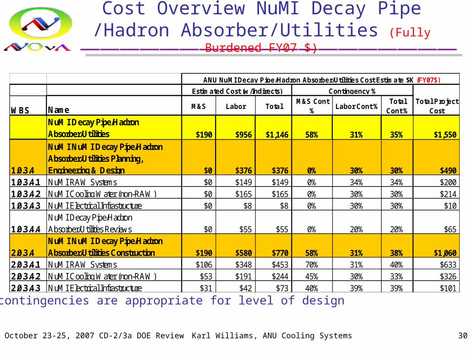
Cost Overview NuMI Decay Pipe /Hadron Absorber/Utilities (Fully Burdened FY07 $)
WBS Name M&S Labor TotalM&S Cont
%Labor Cont %
Total Cont %
NuMI Decay Pipe/Hadron Absorber/Utilities $190 $956 $1,146 58% 31% 35% $1,550
1.0.3.4
NuMI NuMI Decay Pipe/Hadron Absorber/Utilities Planning, Engineering & Design $0 $376 $376 0% 30% 30% $490
1.0.3.4.1 NuMI RAW Systems $0 $149 $149 0% 34% 34% $200
1.0.3.4.2 NuMI Cooling Water (non-RAW) $0 $165 $165 0% 30% 30% $214
1.0.3.4.3 NuMI Electrical Infrastructure $0 $8 $8 0% 30% 30% $10
1.0.3.4.4NuMI Decay Pipe/Hadron Absorber/Utilities Reviews $0 $55 $55 0% 20% 20% $65
2.0.3.4NuMI NuMI Decay Pipe/Hadron Absorber/Utilities Construction $190 $580 $770 58% 31% 38% $1,060
2.0.3.4.1 NuMI RAW Systems $106 $348 $453 70% 31% 40% $633
2.0.3.4.2 NuMI Cooling Water (non-RAW) $53 $191 $244 45% 30% 33% $326
2.0.3.4.3 NuMI Electrical Infrastructure $31 $42 $73 40% 39% 39% $101
ANU NuMI Decay Pipe/Hadron Absorber/Utilities Cost Estimate $K (FY07$)
Estimated Cost (w/Indirects) Contingency %Total Project
Cost
Higher contingencies are appropriate for level of design
October 23-25, 2007 CD-2/3a DOE Review Karl Williams, ANU Cooling Systems 31
Risk and Mitigations
• Reviews– Initial Design Review: Before engineering of mods begins,
to review full system requirements– Final Design Review: Before procurement begins, to
review finalized designs before procurement and construction
• L2 milestones in place for all Cooling Systems at completion of Accelerator Upgrades shutdown tasks
• Risks– MI-8 Pump Room outfitting– PV-9 Pump Vault upgrades– Standard manpower issues (NOvA-doc-1446)

October 23-25, 2007 CD-2/3a DOE Review Karl Williams, ANU Cooling Systems 32
Relevant Recommendations fromSNuMI Review (11/2006)
2.1.4 NuMI UpgradesIt would be prudent to plan any Phase I work in a manner that does not necessitate undoing and/or repeating it for Phase II. This is particularly true for RAW (Radioactive Water) systems.
Status: CompleteWe will make estimates of the demands on the water systems for upgrades beyond the first phase of the upgrade. This will be considered during the scheduled design reviews of the water systems.
Engineering of all cooling systems will be accomplished in such a manner as to keep abreast of the latest project information.