antilock brake
TRANSCRIPT

8/11/2019 Antilock Brake
http://slidepdf.com/reader/full/antilock-brake 1/6
Antilock Brake (ABS)
64. Derive mathematically the conditions for wheel lock up and describemathematically on what condition the front wheels will lock first and on whatcondition the rear wheels will lock first?
During braking, there is a load transfer from the rear axle to the front axle.By considering the equilibrium of moments about the front and rear axles,
When the braking forces reach the maximum for the front and the rear wheels,the wheels are at the point of sliding. Any further increase in the braking forcewould cause the wheels to lock up.
For a given vehicle, given brake proportioning and μ, the front wheels will lockfirst if,
For a given vehicle, given brake proportioning and μ, the rear
wheels will lock first if,
65. What are the physical implications of wheel lock up?
When the rear wheels lock up first, the vehicle will lose directional stability.When the rear wheels lock, the capability of the rear wheels to resist lateralforce is reduced to zero.If some slight lateral movement of the rear wheels is initiated by side wind, roadcamber, or centrifugal force, a yawing moment due to the inertia force about theyaw center of the front axle will be developed. As the yaw motion progresses,

8/11/2019 Antilock Brake
http://slidepdf.com/reader/full/antilock-brake 2/6
the moment arm of the inertia force increases, resulting in an increase in yawacceleration. As the rear end of the vehicle swings around 90°, the moment armgradually decreases, and eventually the vehicle rotates 180°, with the rear endleading the front end. The lock up of front wheels will cause a loss of directionalcontrol, and the driver will no longer be able to exercise effective steering.
The front wheel lock up does not cause directional instability.
66. Define longitudinal wheel slip.Longitudinal wheel slip:
67. How the longitudinal wheel slip is related to the frictional coefficient? Use acharacteristic graph in support of your answer.
Under a locked wheel condition, μ falls to its sliding value, and the vehicle’sability to sustain side force is reduced to almost null.
The objective is to maximize the braking force Fb == μ Nv.• The maximum value of Fb is attained when the frictional coefficient at the tier-road surface reaches its maximum ( μ p).• From the μ - longitudinal wheel slip curve, μ p reaches its maximum around aslip value of 20%

8/11/2019 Antilock Brake
http://slidepdf.com/reader/full/antilock-brake 3/6
68. Describe the basic working principle of the ABS using characteristic graphs.
The basic function of an antilock brake is to monitor the operating conditions ofthe wheel and to control the applied braking torque by modulating the brake
pressure so as to prevent the wheels from becoming locked, and ideally to keepit operating within a desired range of slip.
Maximize frictional coefficient by maintaining Slip within a specified Zone
69. What is the desired slip range to avoid wheel locking and how this isachieved?
To avoid wheel locking the slip range should be between 15-25%. Amicrocontroller can be applied to the control system to achieve this range.
70. Draw a block diagram of the ABS and describe the functions of individualblocks.
Sensors with electromagnetic pulse pickups and toothed wheels areusually used to monitor the rotation of the wheels or the rotatingcomponents of the driveline (e.g. crankshaft).
In the control unit, after the signals generated by the sensors have been
processed, the measured parameters and/or those derived from themare compared with the corresponding predetermined threshold values.
8/11/2019 Antilock Brake
http://slidepdf.com/reader/full/antilock-brake 4/6
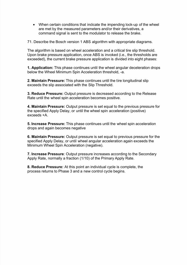
When certain conditions that indicate the impending lock-up of the wheelare met by the measured parameters and/or their derivatives, acommand signal is sent to the modulator to release the brake.
71. Describe the Bosch version 1 ABS algorithm with appropriate diagrams.
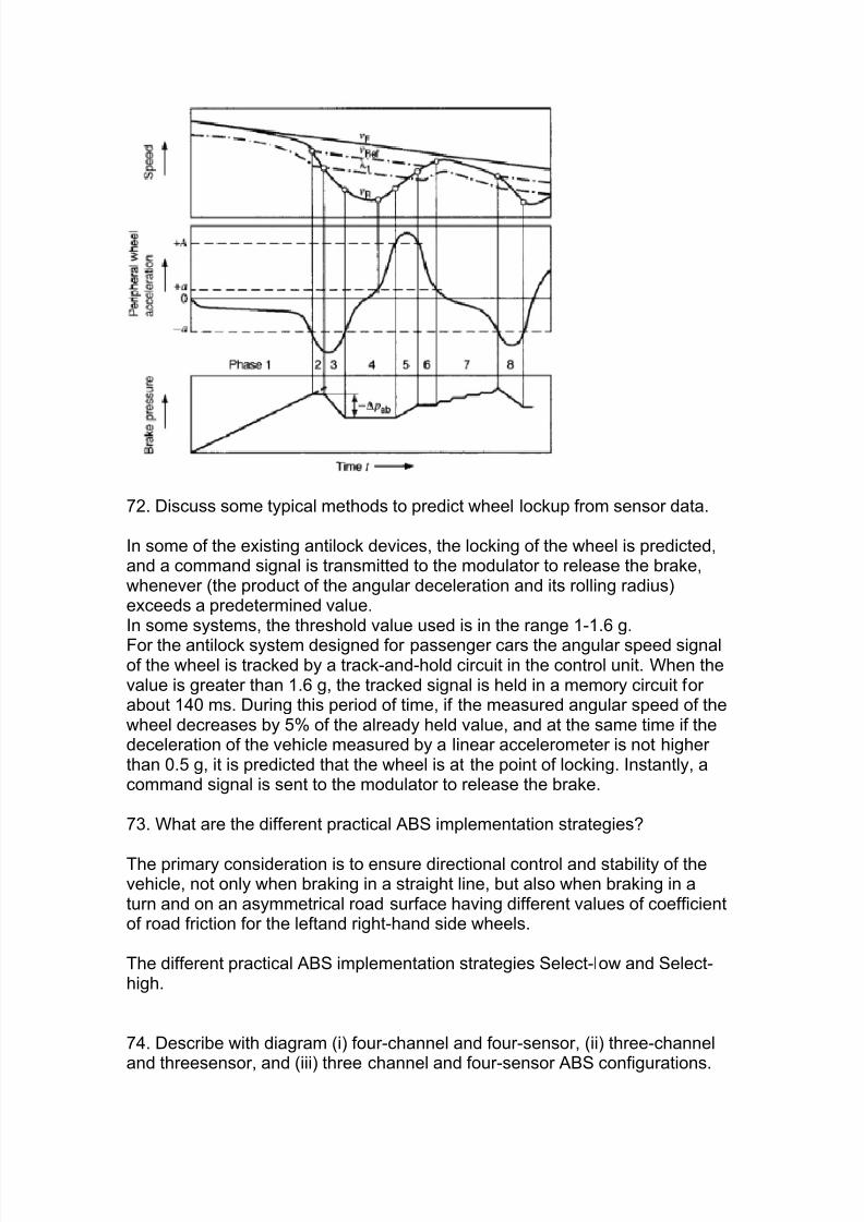
The algorithm is based on wheel acceleration and a critical tire slip threshold.Upon brake pressure application, once ABS is invoked (i.e., the thresholds areexceeded), the current brake pressure application is divided into eight phases:
1. Application: This phase continues until the wheel angular deceleration dropsbelow the Wheel Minimum Spin Acceleration threshold, -a.
2. Maintain Pressure: This phase continues until the tire longitudinal slipexceeds the slip associated with the Slip Threshold.
3. Reduce Pressure: Output pressure is decreased according to the ReleaseRate until the wheel spin acceleration becomes positive.
4. Maintain Pressure: Output pressure is set equal to the previous pressure forthe specified Apply Delay, or until the wheel spin acceleration (positive)exceeds +A.
5. Increase Pressure: This phase continues until the wheel spin accelerationdrops and again becomes negative
6. Maintain Pressure: Output pressure is set equal to previous pressure for thespecified Apply Delay, or until wheel angular acceleration again exceeds theMinimum Wheel Spin Acceleration (negative).
7. Increase Pressure : Output pressure increases according to the Secondary Apply Rate, normally a fraction (1/10) of the Primary Apply Rate.
8. Reduce Pressure: At this point an individual cycle is complete, theprocess returns to Phase 3 and a new control cycle begins.
8/11/2019 Antilock Brake
http://slidepdf.com/reader/full/antilock-brake 5/6
72. Discuss some typical methods to predict wheel lockup from sensor data.
In some of the existing antilock devices, the locking of the wheel is predicted,and a command signal is transmitted to the modulator to release the brake,whenever (the product of the angular deceleration and its rolling radius)exceeds a predetermined value.In some systems, the threshold value used is in the range 1-1.6 g.For the antilock system designed for passenger cars the angular speed signalof the wheel is tracked by a track-and-hold circuit in the control unit. When thevalue is greater than 1.6 g, the tracked signal is held in a memory circuit forabout 140 ms. During this period of time, if the measured angular speed of thewheel decreases by 5% of the already held value, and at the same time if thedeceleration of the vehicle measured by a linear accelerometer is not higherthan 0.5 g, it is predicted that the wheel is at the point of locking. Instantly, acommand signal is sent to the modulator to release the brake.
73. What are the different practical ABS implementation strategies?
The primary consideration is to ensure directional control and stability of thevehicle, not only when braking in a straight line, but also when braking in aturn and on an asymmetrical road surface having different values of coefficientof road friction for the leftand right-hand side wheels.
The different practical ABS implementation strategies Select-low and Select-high.
74. Describe with diagram (i) four-channel and four-sensor, (ii) three-channel
and threesensor, and (iii) three channel and four-sensor ABS configurations.

8/11/2019 Antilock Brake
http://slidepdf.com/reader/full/antilock-brake 6/6
75. What are the control strategies for ABS?
"Select-low" means that the control unit will use the information from the slowerof the two wheels to jointly control both wheels with the same brake pressure.
"select-high" means that the control unit will use the information from the fasterof the two wheels to control the brake pressure applied to both wheels.