ansys maxwell automation and customization productivity... · • torque speed curve computation...
TRANSCRIPT
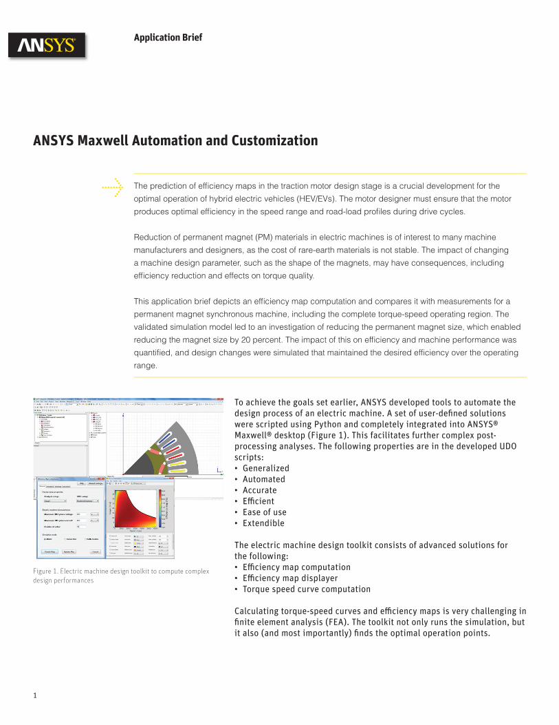
To achieve the goals set earlier, ANSYS developed tools to automate the design process of an electric machine. A set of user-defi ned solutions were scripted using Python and completely integrated into ANSYS® Maxwell® desktop (Figure 1). This facilitates further complex post-processing analyses. The following properties are in the developed UDO scripts:• Generalized• Automated• Accurate• Effi cient • Ease of use• Extendible
The electric machine design toolkit consists of advanced solutions for the following: • Effi ciency map computation• Effi ciency map displayer• Torque speed curve computation
Calculating torque-speed curves and effi ciency maps is very challenging in fi nite element analysis (FEA). The toolkit not only runs the simulation, but it also (and most importantly) fi nds the optimal operation points.
Application Brief
ANSYS Maxwell Automation and Customization
The prediction of effi ciency maps in the traction motor design stage is a crucial development for the
optimal operation of hybrid electric vehicles (HEV/EVs). The motor designer must ensure that the motor
produces optimal effi ciency in the speed range and road-load profi les during drive cycles.
Reduction of permanent magnet (PM) materials in electric machines is of interest to many machine
manufacturers and designers, as the cost of rare-earth materials is not stable. The impact of changing
a machine design parameter, such as the shape of the magnets, may have consequences, including
effi ciency reduction and effects on torque quality.
This application brief depicts an effi ciency map computation and compares it with measurements for a
permanent magnet synchronous machine, including the complete torque-speed operating region. The
validated simulation model led to an investigation of reducing the permanent magnet size, which enabled
reducing the magnet size by 20 percent. The impact of this on effi ciency and machine performance was
quantifi ed, and design changes were simulated that maintained the desired effi ciency over the operating
range.
1
Figure 1. Electric machine design toolkit to compute complex design performances
ANSYS Maxwell Automation and Customization
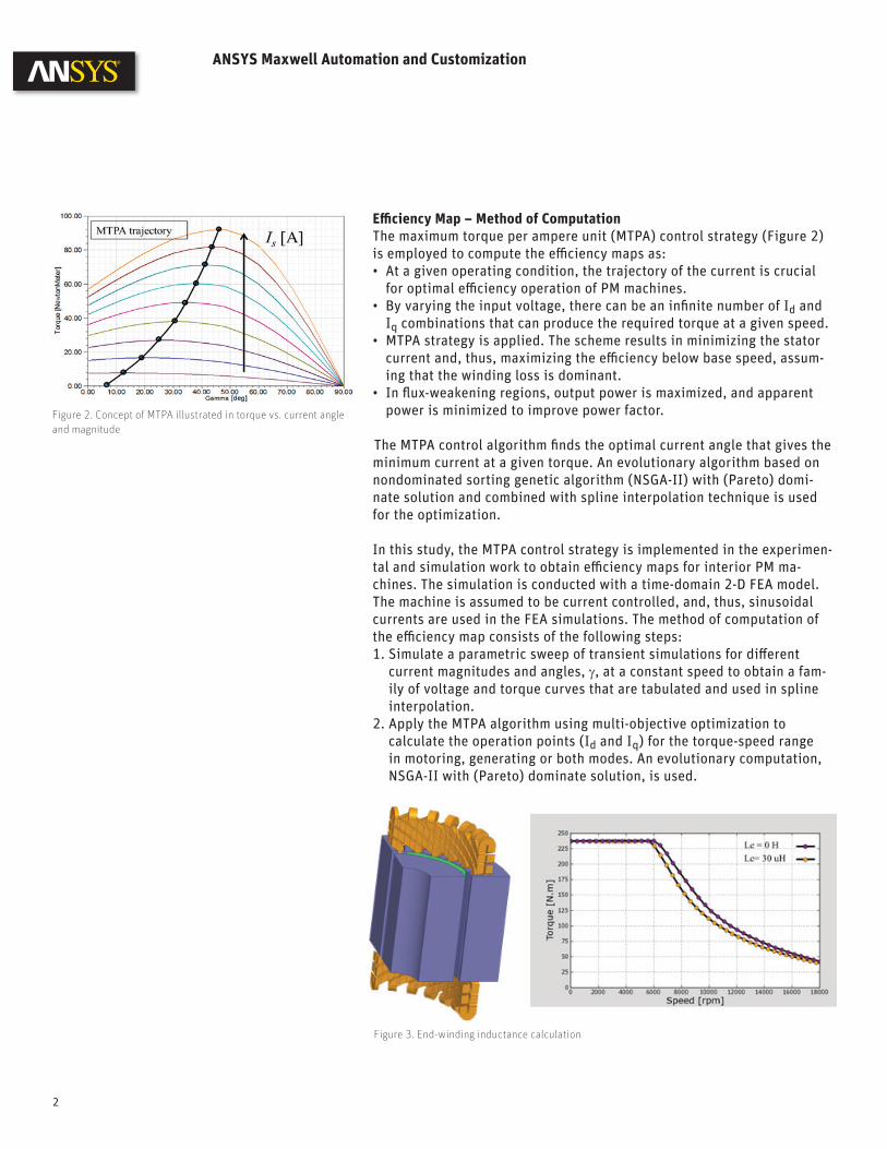
Effi ciency Map – Method of ComputationThe maximum torque per ampere unit (MTPA) control strategy (Figure 2) is employed to compute the effi ciency maps as:• At a given operating condition, the trajectory of the current is crucial
for optimal effi ciency operation of PM machines.• By varying the input voltage, there can be an infi nite number of Id and
Iq combinations that can produce the required torque at a given speed.• MTPA strategy is applied. The scheme results in minimizing the stator
current and, thus, maximizing the effi ciency below base speed, assum-ing that the winding loss is dominant.
• In fl ux-weakening regions, output power is maximized, and apparent power is minimized to improve power factor.
The MTPA control algorithm fi nds the optimal current angle that gives the minimum current at a given torque. An evolutionary algorithm based on nondominated sorting genetic algorithm (NSGA-II) with (Pareto) domi-nate solution and combined with spline interpolation technique is used for the optimization.
In this study, the MTPA control strategy is implemented in the experimen-tal and simulation work to obtain effi ciency maps for interior PM ma-chines. The simulation is conducted with a time-domain 2-D FEA model. The machine is assumed to be current controlled, and, thus, sinusoidal currents are used in the FEA simulations. The method of computation of the effi ciency map consists of the following steps:1. Simulate a parametric sweep of transient simulations for diff erent
current magnitudes and angles, γ, at a constant speed to obtain a fam-ily of voltage and torque curves that are tabulated and used in spline interpolation.
2. Apply the MTPA algorithm using multi-objective optimization to calculate the operation points (Id and Iq) for the torque-speed range in motoring, generating or both modes. An evolutionary computation, NSGA-II with (Pareto) dominate solution, is used.
Figure 2. Concept of MTPA illustrated in torque vs. current angle and magnitude
Figure 3. End-winding inductance calculation
2
3. Run the fi nal simulations using the calculated operation points found with the MTPA. These operation points are simulated at the whole torque-speed range to compute the core loss and eddy-current magnet loss at diff erent supply frequencies.
4. Compute the effi ciency from the output power and total losses that include winding loss, core loss, eddy-current loss in the magnets and mechanical loss.
The method off ers the following advantages:1. Requires only voltage and current limits as inputs and automatically
applies the MTPA algorithm and computes the optimal control angle at the whole torque-speed range accordingly
2. Requires running only a parametric sweep of the current and current angle at a single speed. The torque is assumed to be independent of the speed in current-fed machines. The voltage is assumed to satisfy constant volts per hertz relation. These are considered to be valid as-sumptions in synchronous machines in which the losses, including core loss and eddy-current loss, have minimal infl uence on the torque and back emf production.
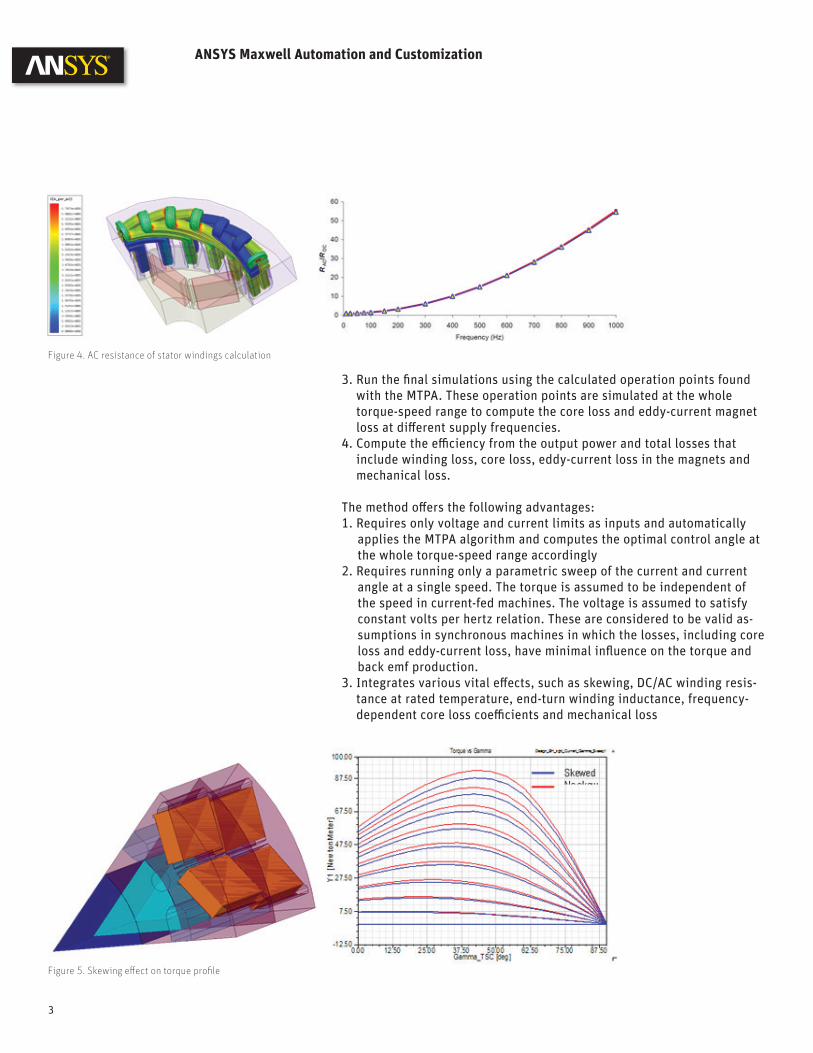
3. Integrates various vital eff ects, such as skewing, DC/AC winding resis-tance at rated temperature, end-turn winding inductance, frequency-dependent core loss coeffi cients and mechanical loss
Figure 4. AC resistance of stator windings calculation
Figure 5. Skewing eff ect on torque profi le
ANSYS Maxwell Automation and Customization
3
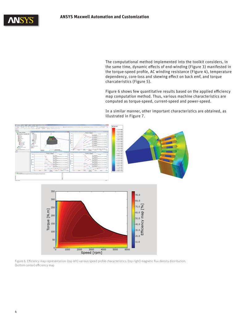
The computational method implemented into the toolkit considers, in the same time, dynamic eff ects of end-winding (Figure 3) manifested in the torque-speed profi le, AC winding resistance (Figure 4), temperature dependency, core-loss and skewing eff ect on back emf, and torque charcateristics (Figure 5).
Figure 6 shows few quantitative results based on the applied effi ciency map computation method. Thus, various machine characteristics are computed as torque-speed, current-speed and power-speed.
In a similar manner, other important characteristics are obtained, as illustrated in Figure 7.
ANSYS Maxwell Automation and Customization
Figure 6. Effi ciency map representation: (top left) various speed profi le characteristics; (top right) magnetic fl ux density distribution; (bottom center) effi ciency map
4

ANSYS, Inc. is one of the world’s leading engineering simulation software provid-ers. Its technology has enabled customers to predict with accuracy that their prod-uct designs will thrive in the real world. The companyoff ers a common platform of fully integrated multiphysics software tools designed to optimize product develop-ment processes for a wide range of industries, including aerospace, automotive, civil engineering, consumer products, chemical process, electronics, environ-mental, healthcare, marine, power, sports and others. Applied to design concept, fi nal-stage testing, validation and trouble-shooting existing designs, software from ANSYS can signifi cantly speed design and development times, reduce costs, and provide insight and understanding into product and process performance.Visit www.ansys.com for more information.
ANSYS, Inc.Southpointe275 Technology DriveCanonsburg, PA [email protected]
© 2013 ANSYS, Inc. All Rights Reserved.
Figure 7. Machine performance characteristics: (top left) current map; (top right) voltage map; (bottom left) power factor map; (bottom right) torque ripple map
ANSYS Maxwell Automation and Customization
Design Challenges and RequirementsThe established design fl ow responds to the challenges in hybrid electric technology innovation:• Shorter design cycle - Industry innovations occur at a rapid pace and competition is fi erce• Increasing battery complexity - 3 million element cell model - Entire pack thermal model ~ 500 million cells, calling for meshing and
simulating complex geometries accurately and quickly• Increased performance - Maximize range - Maximize fuel effi ciency - Maximize power delivery and power management; power available
rapidly decreases with lower cell temperature• Increased safety - Heating/cooling system of the pack ensures cell temperature to be
lower than the maximum allowed value under all vehicle operating and ambient conditions to prevent thermal runaway
• Increased lifespan - Heating/cooling system of the pack maintains as constant-as-possible
cell temperature of 30 C under all vehicle operating and ambient conditions
White Paper
End-To-End Cell–Pack–System Solution: Rechargeable Lithium-Ion Battery
Industry has become more interested in developing optimal energy storage systems as a result of increasing gasoline prices and environmental concerns. A major application for energy stor-age use is hybrid electric vehicles (HEVs) and electric vehicles (EVs). The rechargeable energy storage system is a key design issue, as it dominates overall vehicle performance. The system as a whole must deliver high performance in terms of energy density and power management throughout a variety of driving profi les. The batteries are key elements in sustaining power and energy requirements of the system. However, in many applications the required power and thermal management are key factors for battery sizing. Thermal stability, charge capabili-ties, lifecycle and cost are also important considerations during the system design process.
ANSYS helps engineers deliver hybrid electric vehicle innovation through end-to-end cell–pack–system simulation that includes multiple physics (electrochemistry, electrical, electron-ics, thermal, fl uidic) and controls (embedded software). A simulation-based approach enables designers to achieve shorter design cycles and optimize battery performance, safety and lifespan.
1
End-To-End Cell–Pack–System Solution: Rechargeable Lithium-Ion Battery
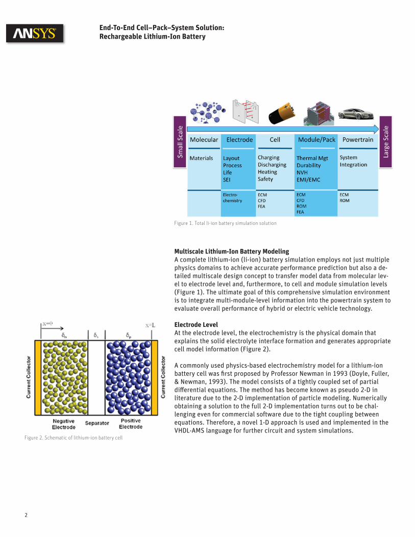
Multiscale Lithium-Ion Battery ModelingA complete lithium-ion (li-ion) battery simulation employs not just multiple physics domains to achieve accurate performance prediction but also a de-tailed multiscale design concept to transfer model data from molecular lev-el to electrode level and, furthermore, to cell and module simulation levels (Figure 1). The ultimate goal of this comprehensive simulation environment is to integrate multi-module-level information into the powertrain system to evaluate overall performance of hybrid or electric vehicle technology.
Electrode LevelAt the electrode level, the electrochemistry is the physical domain that explains the solid electrolyte interface formation and generates appropriate cell model information (Figure 2).
A commonly used physics-based electrochemistry model for a lithium-ion battery cell was fi rst proposed by Professor Newman in 1993 (Doyle, Fuller, & Newman, 1993). The model consists of a tightly coupled set of partial diff erential equations. The method has become known as pseudo 2-D in literature due to the 2-D implementation of particle modeling. Numerically obtaining a solution to the full 2-D implementation turns out to be chal-lenging even for commercial software due to the tight coupling between equations. Therefore, a novel 1-D approach is used and implemented in the VHDL-AMS language for further circuit and system simulations.
Figure 1. Total li-ion battery simulation solution
Figure 2. Schematic of lithium-ion battery cell
2

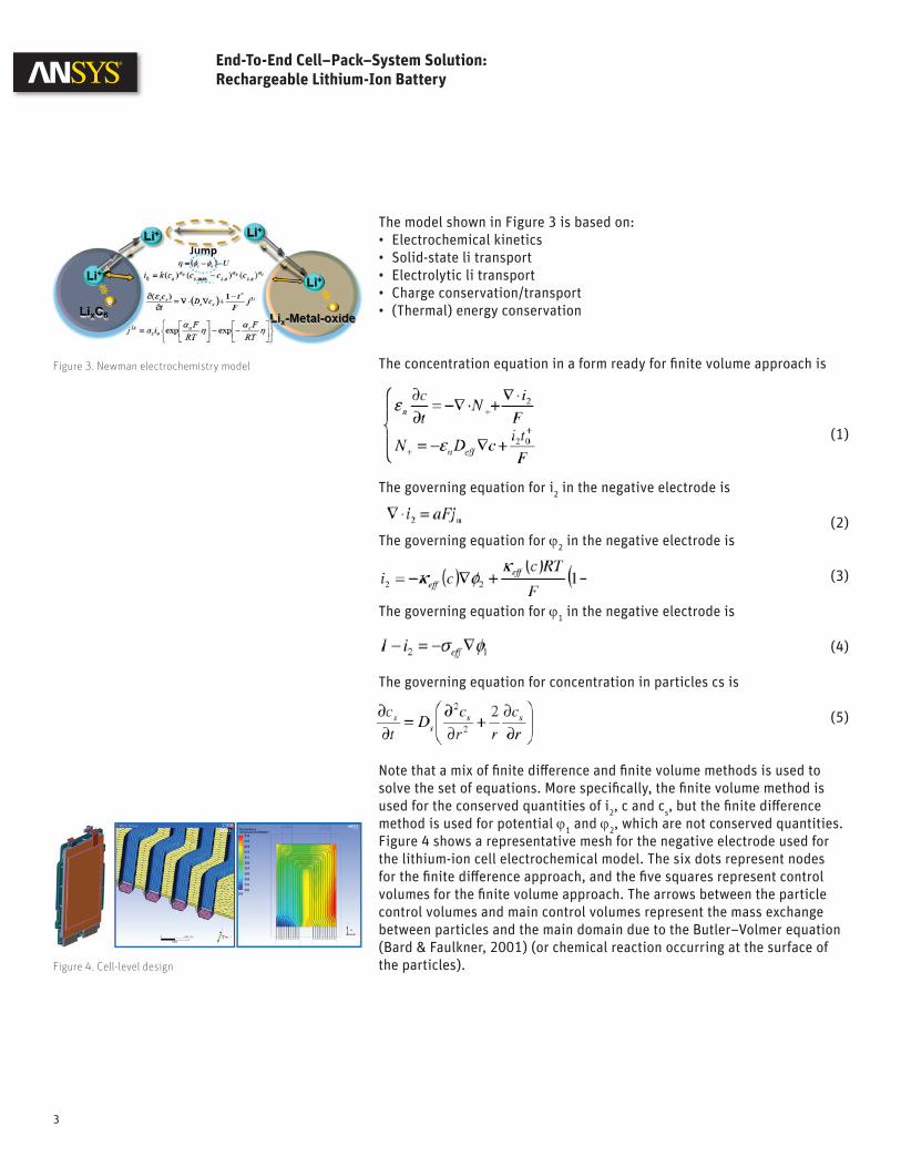
The model shown in Figure 3 is based on:• Electrochemical kinetics• Solid-state li transport• Electrolytic li transport• Charge conservation/transport• (Thermal) energy conservation
The concentration equation in a form ready for fi nite volume approach is
(1)
The governing equation for i2 in the negative electrode is
(2)The governing equation for ϕ2 in the negative electrode is
(3)
The governing equation for ϕ1 in the negative electrode is
(4)
The governing equation for concentration in particles cs is
(5)
Note that a mix of fi nite diff erence and fi nite volume methods is used to solve the set of equations. More specifi cally, the fi nite volume method is used for the conserved quantities of i2, c and cs, but the fi nite diff erence method is used for potential ϕ1 and ϕ2, which are not conserved quantities. Figure 4 shows a representative mesh for the negative electrode used for the lithium-ion cell electrochemical model. The six dots represent nodes for the fi nite diff erence approach, and the fi ve squares represent control volumes for the fi nite volume approach. The arrows between the particle control volumes and main control volumes represent the mass exchange between particles and the main domain due to the Butler–Volmer equation (Bard & Faulkner, 2001) (or chemical reaction occurring at the surface of the particles).
Figure 3. Newman electrochemistry model
Figure 4. Cell-level design
3
End-To-End Cell–Pack–System Solution: Rechargeable Lithium-Ion Battery
Cell LevelDetailed design simulation at the cell level uses computational fl uid dynamics (CFD) analysis.
CFD can be used for battery thermal management analysis; however, CFD tools can be expensive for large systems-level transient analysis. Due to the size of the CFD models, the simulation software can be cumbersome to couple with an electrical circuit model for large system analysis.
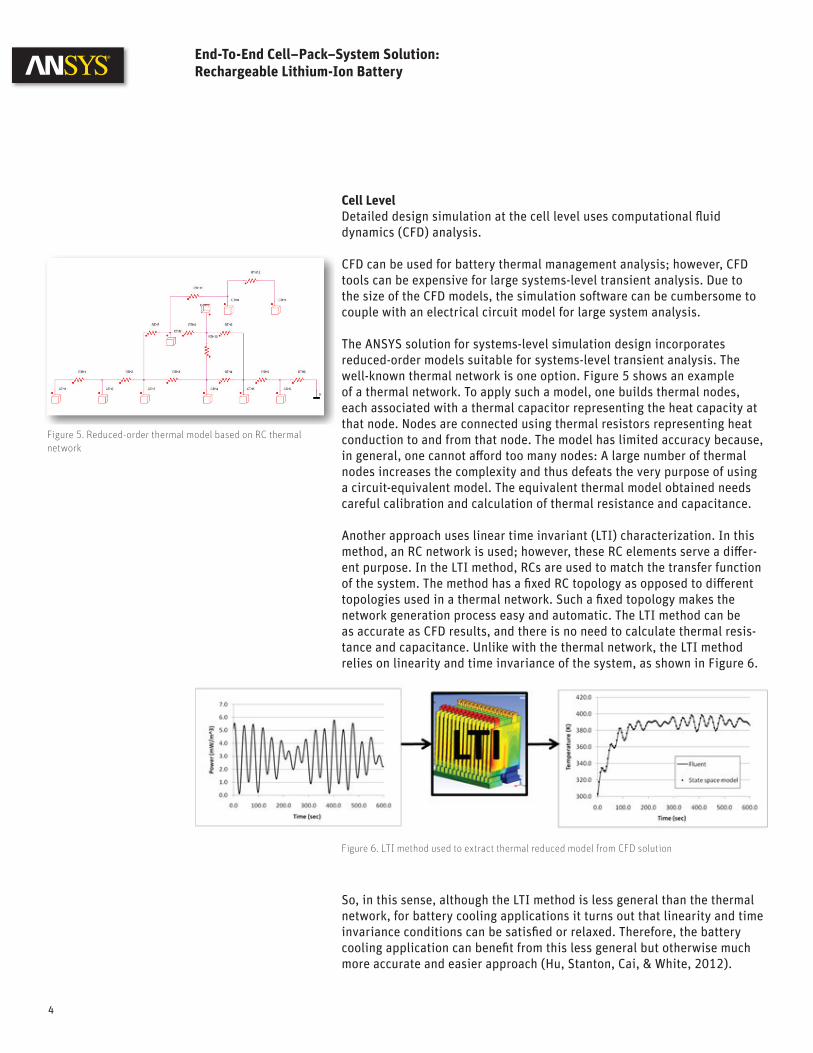
The ANSYS solution for systems-level simulation design incorporates reduced-order models suitable for systems-level transient analysis. The well-known thermal network is one option. Figure 5 shows an example of a thermal network. To apply such a model, one builds thermal nodes, each associated with a thermal capacitor representing the heat capacity at that node. Nodes are connected using thermal resistors representing heat conduction to and from that node. The model has limited accuracy because, in general, one cannot aff ord too many nodes: A large number of thermal nodes increases the complexity and thus defeats the very purpose of using a circuit-equivalent model. The equivalent thermal model obtained needs careful calibration and calculation of thermal resistance and capacitance.
Another approach uses linear time invariant (LTI) characterization. In this method, an RC network is used; however, these RC elements serve a diff er-ent purpose. In the LTI method, RCs are used to match the transfer function of the system. The method has a fi xed RC topology as opposed to diff erent topologies used in a thermal network. Such a fi xed topology makes the network generation process easy and automatic. The LTI method can be as accurate as CFD results, and there is no need to calculate thermal resis-tance and capacitance. Unlike with the thermal network, the LTI method relies on linearity and time invariance of the system, as shown in Figure 6.
Figure 5. Reduced-order thermal model based on RC thermal network
Figure 6. LTI method used to extract thermal reduced model from CFD solution
So, in this sense, although the LTI method is less general than the thermal network, for battery cooling applications it turns out that linearity and time invariance conditions can be satisfi ed or relaxed. Therefore, the battery cooling application can benefi t from this less general but otherwise much more accurate and easier approach (Hu, Stanton, Cai, & White, 2012).
4
End-To-End Cell–Pack–System Solution: Rechargeable Lithium-Ion Battery

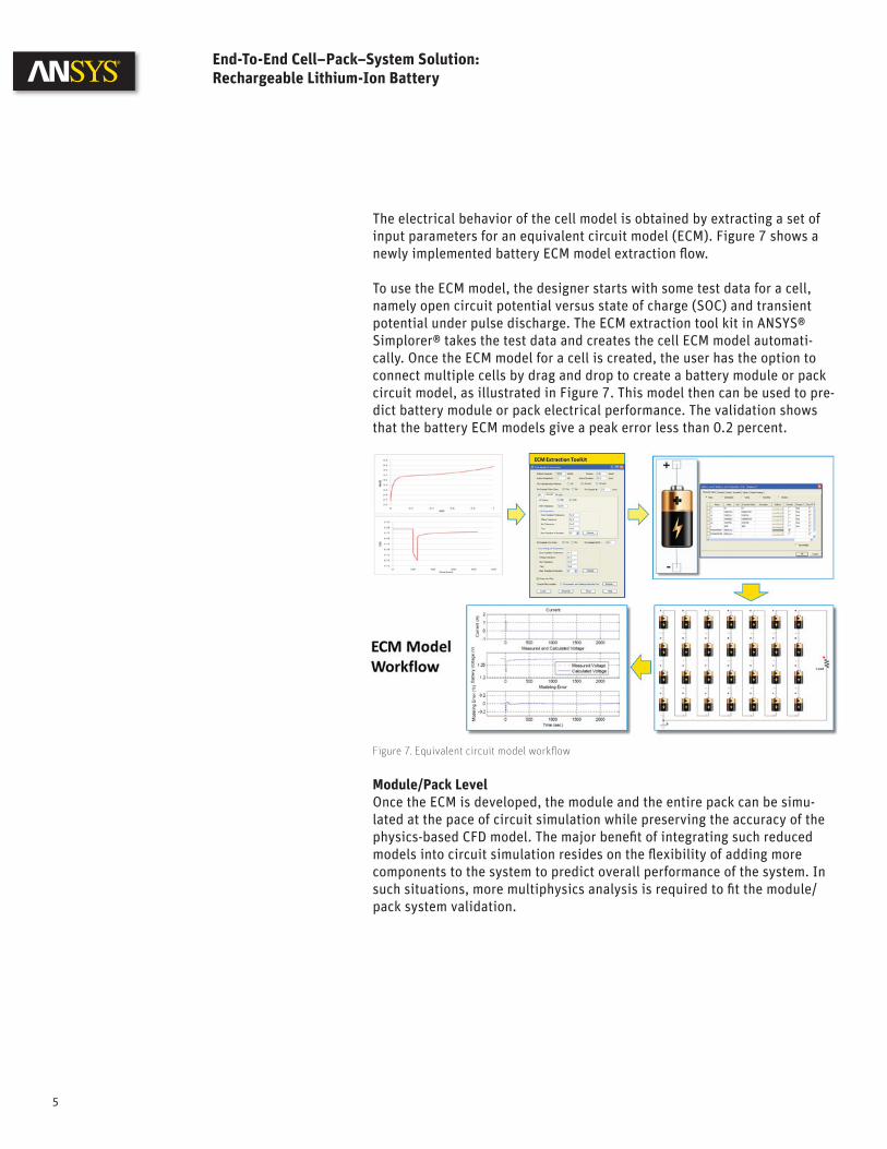
The electrical behavior of the cell model is obtained by extracting a set of input parameters for an equivalent circuit model (ECM). Figure 7 shows a newly implemented battery ECM model extraction fl ow.
To use the ECM model, the designer starts with some test data for a cell, namely open circuit potential versus state of charge (SOC) and transient potential under pulse discharge. The ECM extraction tool kit in ANSYS® Simplorer® takes the test data and creates the cell ECM model automati-cally. Once the ECM model for a cell is created, the user has the option to connect multiple cells by drag and drop to create a battery module or pack circuit model, as illustrated in Figure 7. This model then can be used to pre-dict battery module or pack electrical performance. The validation shows that the battery ECM models give a peak error less than 0.2 percent.
Figure 7. Equivalent circuit model workfl ow
Module/Pack LevelOnce the ECM is developed, the module and the entire pack can be simu-lated at the pace of circuit simulation while preserving the accuracy of the physics-based CFD model. The major benefi t of integrating such reduced models into circuit simulation resides on the fl exibility of adding more components to the system to predict overall performance of the system. In such situations, more multiphysics analysis is required to fi t the module/pack system validation.
5
End-To-End Cell–Pack–System Solution: Rechargeable Lithium-Ion Battery
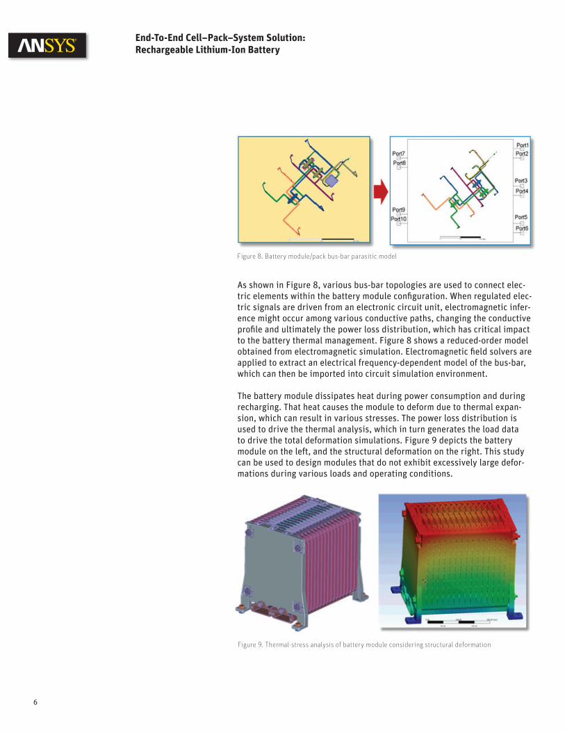
As shown in Figure 8, various bus-bar topologies are used to connect elec-tric elements within the battery module confi guration. When regulated elec-tric signals are driven from an electronic circuit unit, electromagnetic infer-ence might occur among various conductive paths, changing the conductive profi le and ultimately the power loss distribution, which has critical impact to the battery thermal management. Figure 8 shows a reduced-order model obtained from electromagnetic simulation. Electromagnetic fi eld solvers are applied to extract an electrical frequency-dependent model of the bus-bar, which can then be imported into circuit simulation environment.
The battery module dissipates heat during power consumption and during recharging. That heat causes the module to deform due to thermal expan-sion, which can result in various stresses. The power loss distribution is used to drive the thermal analysis, which in turn generates the load data to drive the total deformation simulations. Figure 9 depicts the battery module on the left, and the structural deformation on the right. This study can be used to design modules that do not exhibit excessively large defor-mations during various loads and operating conditions.
Figure 9. Thermal-stress analysis of battery module considering structural deformation
Figure 8. Battery module/pack bus-bar parasitic model
6
End-To-End Cell–Pack–System Solution: Rechargeable Lithium-Ion Battery

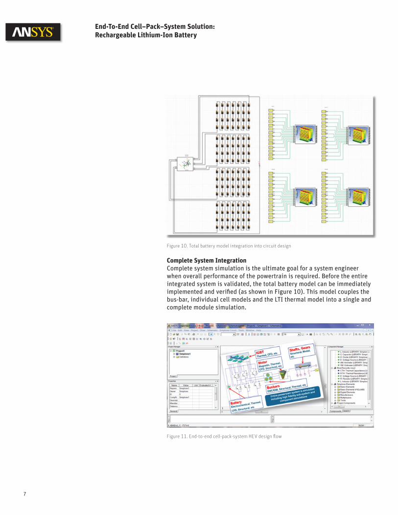
Complete System IntegrationComplete system simulation is the ultimate goal for a system engineer when overall performance of the powertrain is required. Before the entire integrated system is validated, the total battery model can be immediately implemented and verifi ed (as shown in Figure 10). This model couples the bus-bar, individual cell models and the LTI thermal model into a single and complete module simulation.
Figure 10. Total battery model integration into circuit design
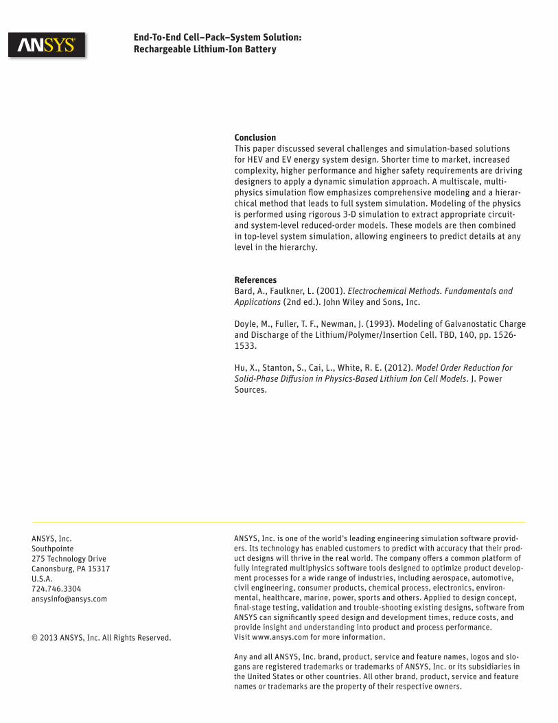
Figure 11. End-to-end cell-pack-system HEV design fl ow
7
End-To-End Cell–Pack–System Solution: Rechargeable Lithium-Ion Battery

Figure 11 depicts the defi nition of the HEV drive train system in which the complete battery model is integrated, including embedded software control. Several other reduced-order models are included in this schematic to provide for multiphysics system simulation at the level of circuit design. This preserves the accuracy of physics-based solutions such as ANSYS Maxwell® for electric motor electromagnetic modeling, ANSYS Q3D Extractor® for parasitic extraction of frequency-dependent behavior for inverter packages and cables, ANSYS Mechanical™ for shaft and gear design models, and ANSYS Simplorer for schematic-based system design.
A suggestive example of complete system simulation of a powertrain application is shown in Figure 12. On such implementation, one can analyze in detail with a higher level of confi dence the fuel consumption at various driving profi les, monitoring battery performance at the same time.
Figure 12. Powertrain application design using ANSYS Simplorer platform
Figure 13. Fuel consumption analysis based on driving profi le
8
End-To-End Cell–Pack–System Solution: Rechargeable Lithium-Ion Battery

ConclusionThis paper discussed several challenges and simulation-based solutions for HEV and EV energy system design. Shorter time to market, increased complexity, higher performance and higher safety requirements are driving designers to apply a dynamic simulation approach. A multiscale, multi-physics simulation fl ow emphasizes comprehensive modeling and a hierar-chical method that leads to full system simulation. Modeling of the physics is performed using rigorous 3-D simulation to extract appropriate circuit- and system-level reduced-order models. These models are then combined in top-level system simulation, allowing engineers to predict details at any level in the hierarchy.
ReferencesBard, A., Faulkner, L. (2001). Electrochemical Methods. Fundamentals and Applications (2nd ed.). John Wiley and Sons, Inc.
Doyle, M., Fuller, T. F., Newman, J. (1993). Modeling of Galvanostatic Charge and Discharge of the Lithium/Polymer/Insertion Cell. TBD, 140, pp. 1526-1533.
Hu, X., Stanton, S., Cai, L., White, R. E. (2012). Model Order Reduction for Solid-Phase Diff usion in Physics-Based Lithium Ion Cell Models. J. Power Sources.
ANSYS, Inc. is one of the world’s leading engineering simulation software provid-ers. Its technology has enabled customers to predict with accuracy that their prod-uct designs will thrive in the real world. The company off ers a common platform of fully integrated multiphysics software tools designed to optimize product develop-ment processes for a wide range of industries, including aerospace, automotive, civil engineering, consumer products, chemical process, electronics, environ-mental, healthcare, marine, power, sports and others. Applied to design concept, fi nal-stage testing, validation and trouble-shooting existing designs, software from ANSYS can signifi cantly speed design and development times, reduce costs, and provide insight and understanding into product and process performance.Visit www.ansys.com for more information.
Any and all ANSYS, Inc. brand, product, service and feature names, logos and slo-gans are registered trademarks or trademarks of ANSYS, Inc. or its subsidiaries in the United States or other countries. All other brand, product, service and feature names or trademarks are the property of their respective owners.
ANSYS, Inc.Southpointe275 Technology DriveCanonsburg, PA [email protected]
© 2013 ANSYS, Inc. All Rights Reserved.
End-To-End Cell–Pack–System Solution: Rechargeable Lithium-Ion Battery

There is a clear global demand for a comprehensive design methodology to support these new applications and satisfy power efficiency requirements. Most research efforts to improve motor design have focused on the motor, rather than the motor-driven system as a whole. Engineers are forced to use a host of often incompatible simulation tools to address the various levels of motor and drive systems, leading to errors and delays in the design cycle or increased cost due to build-and-test iterations. ANSYS® multiphysics and multi-scale system engineering technology is ideal to meet these challenges.
Unique Solution Several calculation techniques are available to predict electric machine performance, including classical closed-form analytical analysis, lumped parameter models based on determination of detailed parameters from finite element analysis, and nonlinear time-domain finite element analysis. Each method has advantages and disadvantages. Selecting the best method can be difficult because it requires the user to understand the differences among calculation methods. The fundamental issue differentiating these methods is the trade-off among model complexity, accuracy and computing time. Engineers use a combination of these calculation techniques as the optimal solution to simulate electric machine performance.
Success in using any simulation software is usability. Ease of use plays a significant role in speeding time to market, because engineers will quickly discard software that is difficult to use or requires in-depth knowledge of numerical simulation techniques. Launching a product quickly requires sim-ulation software that serves a number of purposes: accurate and suitable for use throughout an organization at different stages of the design process by engineers with various levels of knowledge in numerical simulation.
Electric Machine Design Methodology: A Revolutionary Approach
Electric machines are used in novel applications around the world, driven by the need for greater power efficiency in the transportation, aerospace and defense, and industrial automa-tion industries. The automotive sector focuses on the need for hybrid and electric vehicle technology to meet stringent miles-per-gallon standards. The aerospace and defense industry concentrates on replacing existing aircraft power transfer technologies (such as the central hydraulic system) with fault-tolerant electric power, in which major subsystems — including engine starting, primary flight control actuation, pumps and braking — are controlled and driven electronically. In the United States’ industrial sector, more than 40 million electric motors convert electricity into useful work in manufacturing operations. Industry spends over $30 billion (US) annually on electricity dedicated to electric motor-driven systems that drive pumps, fan and blower systems, and air compression.
1
Figure 2. Optimum electromagnetics design flow
Figure 1. Multiphysics and multi-domain electric machine design flow

Electric Machine Design Methodology: A Revolutionary Approach
The ANSYS electric machine design solution is unique in the simulation industry:• Employs the most efficient numerical techniques• Provides highly accurate, comprehensive multiphysics simulation
design of an electric machine• Includes distributed parametric analysis and HPC for robust design• Enables power electronics and embedded control software to be
simulated with a detailed finite element model
Workflow The ANSYS integrated electric machine design methodology enables users to design, analyze and deliver efficient, optimized electric machine and drive designs. The design methodology encompasses a number of ANSYS software programs that address the many design variables involved with creating such a system.
Figure 1 shows the main design flow. The initial design stage is addressed with ANSYS RMxprt™. This specialized software allows users to quickly create a geometric model of the machine from a template-based interface, calculate its performance, and make sizing decisions. Once the initial design is completed, RMxprt creates the complete setup of the 2-D/3-D magnetic design in ANSYS Maxwell®.
Maxwell can execute rigorous performance calculations of the machine, including the motion-induced physics caused by linear translational and rotational motion, advanced hysteresis analysis, demagnetization of per-manent magnets and other critical electromagnetic machine parameters. Maxwell is integrated into ANSYS Workbench™, where it can share the same CAD source with other ANSYS physics-based solvers and couple with ANSYS Mechanical™, ANSYS Fluent® or ANSYS Icepak®.
Workbench also links Maxwell to the system design optimization capability provided by ANSYS DesignXplorer™ software.
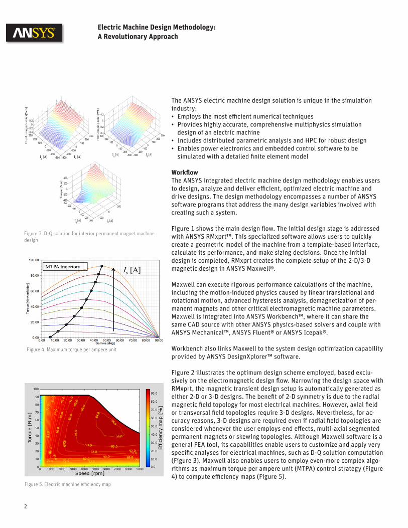
Figure 2 illustrates the optimum design scheme employed, based exclu-sively on the electromagnetic design flow. Narrowing the design space with RMxprt, the magnetic transient design setup is automatically generated as either 2-D or 3-D designs. The benefit of 2-D symmetry is due to the radial magnetic field topology for most electrical machines. However, axial field or transversal field topologies require 3-D designs. Nevertheless, for ac-curacy reasons, 3-D designs are required even if radial field topologies are considered whenever the user employs end effects, multi-axial segmented permanent magnets or skewing topologies. Although Maxwell software is a general FEA tool, its capabilities enable users to customize and apply very specific analyses for electrical machines, such as D-Q solution computation (Figure 3). Maxwell also enables users to employ even-more complex algo-rithms as maximum torque per ampere unit (MTPA) control strategy (Figure 4) to compute efficiency maps (Figure 5).
2
Figure 3. D-Q solution for interior permanent magnet machine design
Figure 4. Maximum torque per ampere unit
Figure 5. Electric machine efficiency map
Electric Machine Design Methodology: A Revolutionary Approach
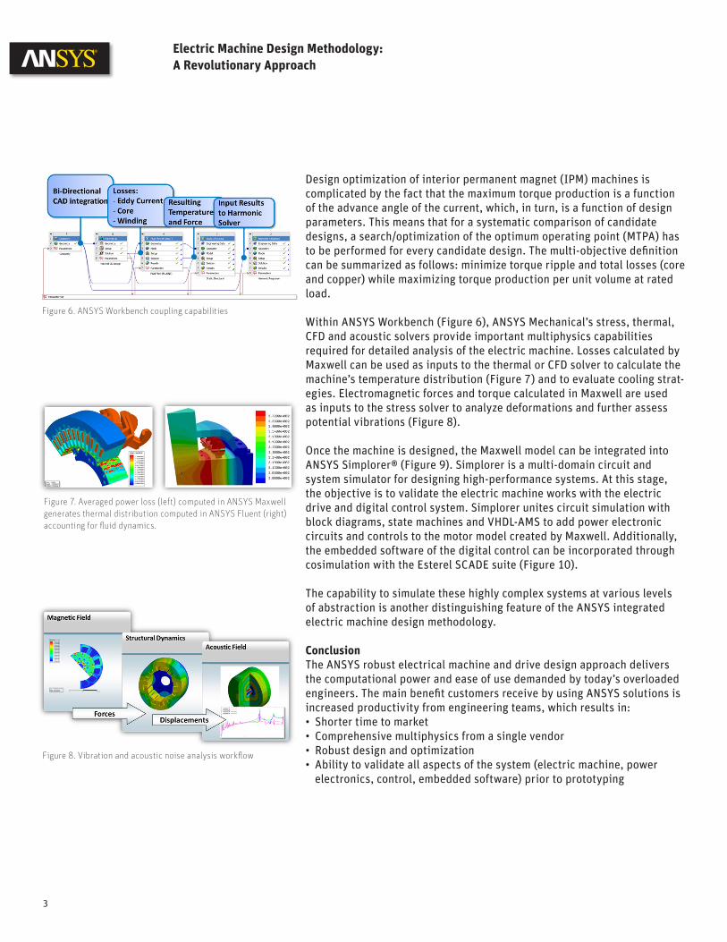
Design optimization of interior permanent magnet (IPM) machines is complicated by the fact that the maximum torque production is a function of the advance angle of the current, which, in turn, is a function of design parameters. This means that for a systematic comparison of candidate designs, a search/optimization of the optimum operating point (MTPA) has to be performed for every candidate design. The multi-objective definition can be summarized as follows: minimize torque ripple and total losses (core and copper) while maximizing torque production per unit volume at rated load.
Within ANSYS Workbench (Figure 6), ANSYS Mechanical’s stress, thermal, CFD and acoustic solvers provide important multiphysics capabilities required for detailed analysis of the electric machine. Losses calculated by Maxwell can be used as inputs to the thermal or CFD solver to calculate the machine’s temperature distribution (Figure 7) and to evaluate cooling strat-egies. Electromagnetic forces and torque calculated in Maxwell are used as inputs to the stress solver to analyze deformations and further assess potential vibrations (Figure 8).
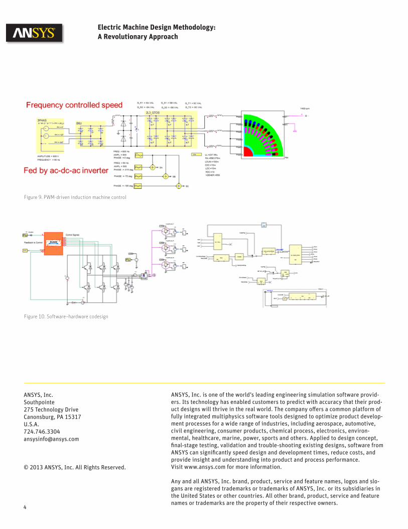
Once the machine is designed, the Maxwell model can be integrated into ANSYS Simplorer® (Figure 9). Simplorer is a multi-domain circuit and system simulator for designing high-performance systems. At this stage, the objective is to validate the electric machine works with the electric drive and digital control system. Simplorer unites circuit simulation with block diagrams, state machines and VHDL-AMS to add power electronic circuits and controls to the motor model created by Maxwell. Additionally, the embedded software of the digital control can be incorporated through cosimulation with the Esterel SCADE suite (Figure 10).
The capability to simulate these highly complex systems at various levels of abstraction is another distinguishing feature of the ANSYS integrated electric machine design methodology.
ConclusionThe ANSYS robust electrical machine and drive design approach delivers the computational power and ease of use demanded by today’s overloaded engineers. The main benefit customers receive by using ANSYS solutions is increased productivity from engineering teams, which results in:• Shorter time to market• Comprehensive multiphysics from a single vendor• Robust design and optimization• Ability to validate all aspects of the system (electric machine, power
electronics, control, embedded software) prior to prototyping
3
Figure 7. Averaged power loss (left) computed in ANSYS Maxwell generates thermal distribution computed in ANSYS Fluent (right) accounting for fluid dynamics.
Figure 8. Vibration and acoustic noise analysis workflow
Figure 6. ANSYS Workbench coupling capabilities

4

ANSYS Maxwell magnetic fi eld formulation is founded on Maxwell’s equations starting with the basic fi eld equations:
(Faraday’s law) (1)
(Gauss’s law) (2)
(Ampere’s law) (3)
in which E is the electric fi eld strength, B is the magnetic fl ux density, H is the magnetic fi eld strength, and J is the electric current density. Obviously, these equations are considered together with the constitutive material equations for both electric fi elds as E=f (J) and magnetic fi eld as B=f (H).
Numerical solution of such equations is based on T-Ω formulation in which Ω is nodal-based magnetic scalar potential, defi ned in the entire solution domain, and T is edge-based electrical vector potential, defi ned only in the conducting eddy-current region (Figure 1). There are several advantages of this formulation:• Avoid unphysical solution due to utilization of edge elements to
model a source component and induced eddy current• Computationally effi cient because in the nonconducting region,
only scalar potential is employed• Numerical stability because no gauging is required to obtain
unique solutions
Application Brief
ANSYS Maxwell Magnetic Field Formulation
There are various variational electromagnetic fi eld formulations using FEA to numerically solve Maxwell’s equations. When choosing the right formulation to be implemented in FEA special mathematical handling is required in order to avoid unphysical solutions and to provide numerical stability and computational effi ciency. This application brief describes the basis for formulation employed in ANSYS Maxwell.
1
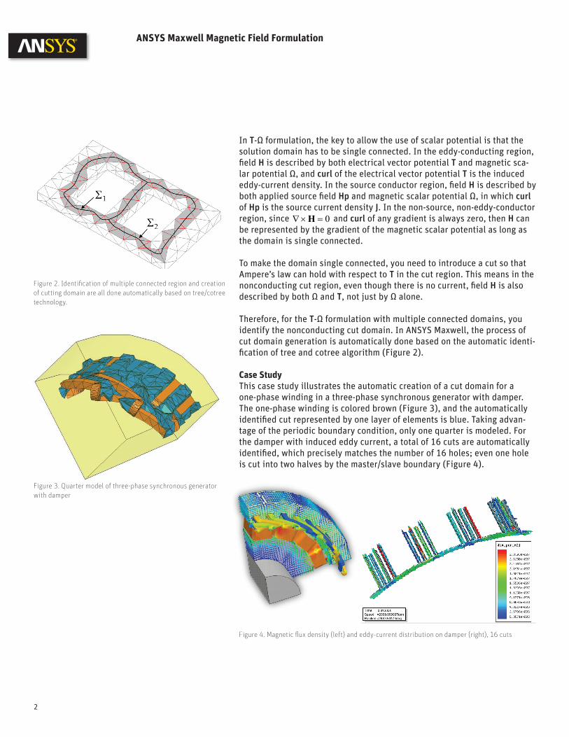
Figure 1. Domain representation for T-Ω formulation

In T-Ω formulation, the key to allow the use of scalar potential is that the solution domain has to be single connected. In the eddy-conducting region, fi eld H is described by both electrical vector potential T and magnetic sca-lar potential Ω, and curl of the electrical vector potential T is the induced eddy-current density. In the source conductor region, fi eld H is described by both applied source fi eld Hp and magnetic scalar potential Ω, in which curl of Hp is the source current density J. In the non-source, non-eddy-conductor region, since 0=×∇ H and curl of any gradient is always zero, then H can be represented by the gradient of the magnetic scalar potential as long as the domain is single connected.
To make the domain single connected, you need to introduce a cut so that Ampere’s law can hold with respect to T in the cut region. This means in the nonconducting cut region, even though there is no current, fi eld H is also described by both Ω and T, not just by Ω alone.
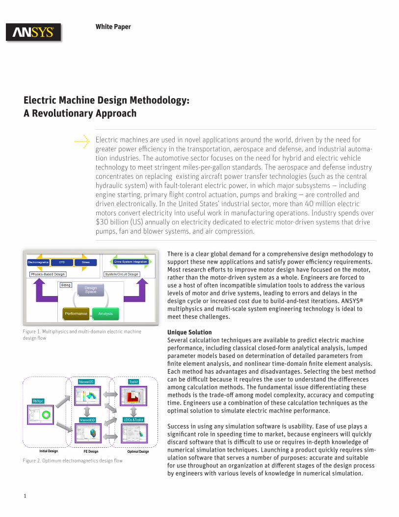
Therefore, for the T-Ω formulation with multiple connected domains, you identify the nonconducting cut domain. In ANSYS Maxwell, the process of cut domain generation is automatically done based on the automatic identi-fi cation of tree and cotree algorithm (Figure 2). Case StudyThis case study illustrates the automatic creation of a cut domain for a one-phase winding in a three-phase synchronous generator with damper. The one-phase winding is colored brown (Figure 3), and the automatically identifi ed cut represented by one layer of elements is blue. Taking advan-tage of the periodic boundary condition, only one quarter is modeled. For the damper with induced eddy current, a total of 16 cuts are automatically identifi ed, which precisely matches the number of 16 holes; even one hole is cut into two halves by the master/slave boundary (Figure 4).
ANSYS Maxwell Magnetic Field Formulation
2
Figure 2. Identifi cation of multiple connected region and creation of cutting domain are all done automatically based on tree/cotree technology.
Figure 3. Quarter model of three-phase synchronous generator with damper
Figure 4. Magnetic fl ux density (left) and eddy-current distribution on damper (right), 16 cuts
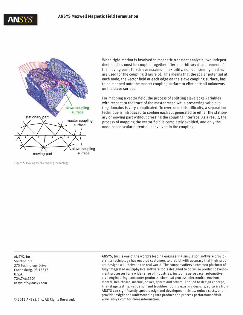
When rigid motion is involved in magnetic transient analysis, two indepen-dent meshes must be coupled together after an arbitrary displacement of the moving part. To achieve maximum fl exibility, non-conforming meshes are used for the coupling (Figure 5). This means that the scalar potential at each node, the vector fi eld at each edge on the slave coupling surface, has to be mapped onto the master coupling surface to eliminate all unknowns on the slave surface.
For mapping a vector fi eld, the process of splitting slave edge variables with respect to the trace of the master mesh while preserving valid cut-ting domains is very complicated. To overcome this diffi culty, a separation technique is introduced to confi ne each cut generated to either the station-ary or moving part without crossing the coupling interface. As a result, the process of mapping the vector fi eld is completely avoided, and only the node-based scalar potential is involved in the coupling.
ANSYS Maxwell Magnetic Field Formulation
Figure 5. Moving mesh coupling technology
ANSYS, Inc. is one of the world’s leading engineering simulation software provid-ers. Its technology has enabled customers to predict with accuracy that their prod-uct designs will thrive in the real world. The companyoff ers a common platform of fully integrated multiphysics software tools designed to optimize product develop-ment processes for a wide range of industries, including aerospace, automotive, civil engineering, consumer products, chemical process, electronics, environ-mental, healthcare, marine, power, sports and others. Applied to design concept, fi nal-stage testing, validation and trouble-shooting existing designs, software from ANSYS can signifi cantly speed design and development times, reduce costs, and provide insight and understanding into product and process performance.Visit www.ansys.com for more information.
ANSYS, Inc.Southpointe275 Technology DriveCanonsburg, PA [email protected]
© 2013 ANSYS, Inc. All Rights Reserved.
© 2014 ANSYS, INC. ANSYS ADVANTAGE Volume VIII | Issue 1 | 2014 11
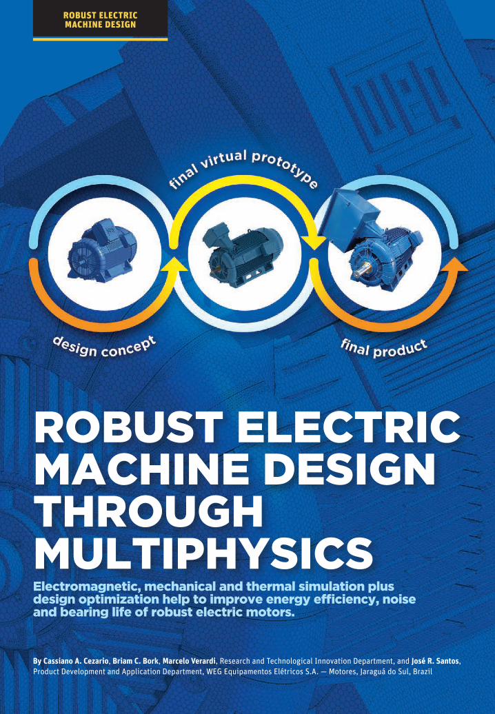
ROBUST ELECTRIC MACHINE DESIGN THROUGH MULTIPHYSICS
By Cassiano A. Cezario, Briam C. Bork, Marcelo Verardi, Research and Technological Innovation Department, and José R. Santos, Product Development and Application Department, WEG Equipamentos Elétricos S.A. — Motores, Jaraguá do Sul, Brazil
Electromagnetic, mechanical and thermal simulation plus design optimization help to improve energy efficiency, noise and bearing life of robust electric motors.
ROBUST ELECTRIC MACHINE DESIGN

© 2014 ANSYS, INC. ANSYS ADVANTAGE Volume VIII | Issue 2 | 2014 12
WEG engineers used a wide range of ANSYS tools to deliver optimal energy efficiency, low operating noise and long bearing life on its new line of electric motors.
WEG’s Robust Design of Electric Machines
Electric motors are the single biggest consumer of electric-ity, accounting for about two-thirds of industrial power consumption and about 45 percent of global power con-
sumption, according to an analysis by the International Energy Agency. The World Energy Outlook 2012 states that the devel-oped world is planning to increase its energy efficiency by 1.8 percent annually over the next 25 years. Much of this improvement must come from advancements in electric motor design. Companies that develop these devices must ensure that motors have low operating noise and long life. Engineers have worked to balance these demands to improve and optimize the design of electric motors for almost two centuries, and now new methods and tools are needed to generate further progress.
WEG is the largest industrial electric motor manufacturer in the Americas and one of the largest manufacturers of indus-trial electric motors in the world, producing more than 10 million units annually. WEG engineers used the ANSYS comprehensive design solution for electric motors to leverage electromagnetic, mechanical and thermal simulation. Design optimization helped the engineering team to deliver optimal energy efficiency, low operating noise and long bearing life on the new W50 electric line
EVALUATE A WIDE RANGE
OF COOLING AIR
PASSAGE DESIGNS
MINIMIZE TOTAL NOISE
GENERATED BY MOTOR
• PREDICT AERODYNAMIC
NOISE
• PREDICT
ELECTROMAGNETIC
NOISE
REDUCE OPERATING
TEMPERATURE OF
BEARING
AUTOMATE DESIGN
EXPLORATION
COMPUTATIONAL FLUID
DYNAMICS (CFD)–
ELECTROMAGNETIC
SIMULATION
ELECTROMAGNETIC–
STRUCTURAL–THERMAL
ANALYSES
CFD–THERMAL
SIMULATIONS
ANSYS DESIGNXPLORER
AND ANSYS WORKBENCH
REDUCE FAN LOSSES
AND IMPROVE ENERGY
EFFICIENCY
LOWER OPERATING NOISE
INCREASE BEARING LIFE
OPTIMIZE MOTOR DESIGN
WITHOUT HAVING TO
MANUALLY EVALUATE
EACH DESIGN ALTERNATIVE
APPLICATION TECHNOLOGY EXPECTED RESULTS OR TARGET
ROBUST ELECTRIC MACHINE DESIGN
Response surface map depicts fan airflow efficiency as a function of several design variables.
ELECTRIC MACHINE DESIGN METHODOLOGY: A REVOLUTIONARY APPROACH
ansys.com/82robust
© 2014 ANSYS, INC. ANSYS ADVANTAGE Volume VIII | Issue 2 | 2014 13
of motors. The broad range of ANSYS capa-bilities was instrumental in designing and optimizing the electric motor with-out the need to individually evaluate each design alternative.
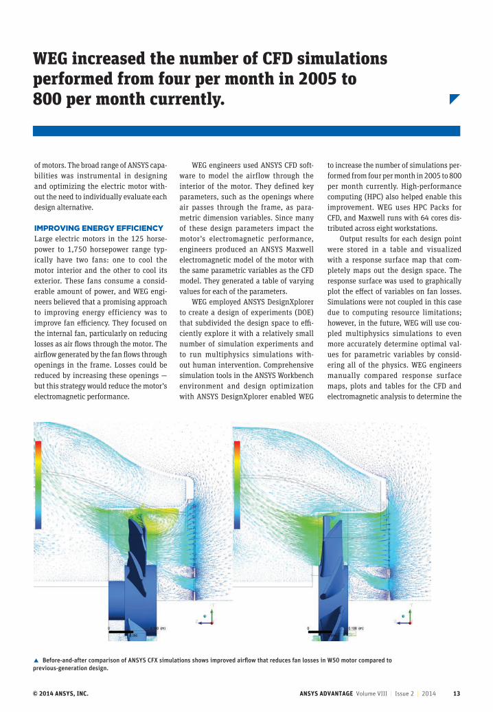
IMPROVING ENERGY EFFICIENCYLarge electric motors in the 125 horse-power to 1,750 horsepower range typ-ically have two fans: one to cool the motor interior and the other to cool its exterior. These fans consume a consid-erable amount of power, and WEG engi-neers believed that a promising approach to improving energy efficiency was to improve fan efficiency. They focused on the internal fan, particularly on reducing losses as air flows through the motor. The airflow generated by the fan flows through openings in the frame. Losses could be reduced by increasing these openings — but this strategy would reduce the motor’s electromagnetic performance.
WEG engineers used ANSYS CFD soft-ware to model the airflow through the interior of the motor. They defined key parameters, such as the openings where air passes through the frame, as para-metric dimension variables. Since many of these design parameters impact the motor’s electromagnetic performance, engineers produced an ANSYS Maxwell electromagnetic model of the motor with the same parametric variables as the CFD model. They generated a table of varying values for each of the parameters.
WEG employed ANSYS DesignXplorer to create a design of experiments (DOE) that subdivided the design space to effi-ciently explore it with a relatively small number of simulation experiments and to run multiphysics simulations with-out human intervention. Comprehensive simulation tools in the ANSYS Workbench environment and design optimization with ANSYS DesignXplorer enabled WEG
to increase the number of simulations per-formed from four per month in 2005 to 800 per month currently. High-performance computing (HPC) also helped enable this improvement. WEG uses HPC Packs for CFD, and Maxwell runs with 64 cores dis-tributed across eight workstations.
Output results for each design point were stored in a table and visualized with a response surface map that com-pletely maps out the design space. The response surface was used to graphically plot the effect of variables on fan losses. Simulations were not coupled in this case due to computing resource limitations; however, in the future, WEG will use cou-pled multiphysics simulations to even more accurately determine optimal val-ues for parametric variables by consid-ering all of the physics. WEG engineers manually compared response surface maps, plots and tables for the CFD and electromagnetic analysis to determine the
Before-and-after comparison of ANSYS CFX simulations shows improved airflow that reduces fan losses in W50 motor compared to previous-generation design.
WEG increased the number of CFD simulations performed from four per month in 2005 to 800 per month currently.

© 2014 ANSYS, INC. ANSYS ADVANTAGE Volume VIII | Issue 2 | 2014 14
ROBUST ELECTRIC MACHINE DESIGN
ANSYS multiphysics tools help WEG deliver best-in-class performance for electric motors while substantially reducing the lead time and cost of the product development process.
ANSYS Maxwell simulation helps to optimize the trade-off between fan losses and electromagnetic performance.
Fan efficiency plotted against two design variables (one on x axis and other in multiple plots)
combinations of parametric variables that delivered the best mix of performance. Engineers then reran the electromagnetic and CFD simulation for the best combina-tions and selected the one that delivered the best performance: a substantial reduc-tion in fan losses and a resulting improve-ment in energy efficiency without any sacrifice in electromagnetic performance.
REDUCING NOISEWEG engineers also wanted to reduce the noise generated by the new W50 motor design. An electric motor primarily gen-erates noise through two independent sources: aerodynamic and electromag-netic. Aerodynamic noise is generated by the fan rotor and transmitted through the air; WEG engineers used ANSYS CFD to optimize the fan rotor geometry to mini-mize aerodynamic noise. Electromagnetic noise is created by the interaction of mag-netic fields produced by stator and rotor. In extreme cases in which the resultant force frequency excites the natural fre-quencies of the mechanical structure, this noise will be dramatically amplified.
WEG engineers used ANSYS CFD to optimize the internal fan system. Engineers designed a new internal fan system to reduce the length of the motor, which improved the dynamic perfor-mance. However, the original design was not acceptable, so engineers used ANSYS DesignXplorer to optimize the internal fan geometry and develop a new solu-tion that met the requirements. The new internal fan reduces vibration, improves power density of the motor, and increases the maximum rotating speed.
To predict and avoid electromagnetic noise of the motor prior to the prototyping stage, WEG engineers used electromagnetic simulation to calculate the electromagnetic force and losses. These quantities are used as inputs to the structural and thermal sim-ulation to predict mechanical vibrations. WEG engineers used the ANSYS Application Customization Toolkit to implement the methodology of topological optimization to increase the natural frequency of the frame. They then set up parametric vari-ables and used ANSYS DesignXplorer to run a table of design points and optimize the design to produce the lowest levels of noise.
IMPROVING BEARING LIFEBearings are usually the first component to fail during the lifetime of an electric
© 2014 ANSYS, INC. ANSYS ADVANTAGE Volume VIII | Issue 2 | 2014 15
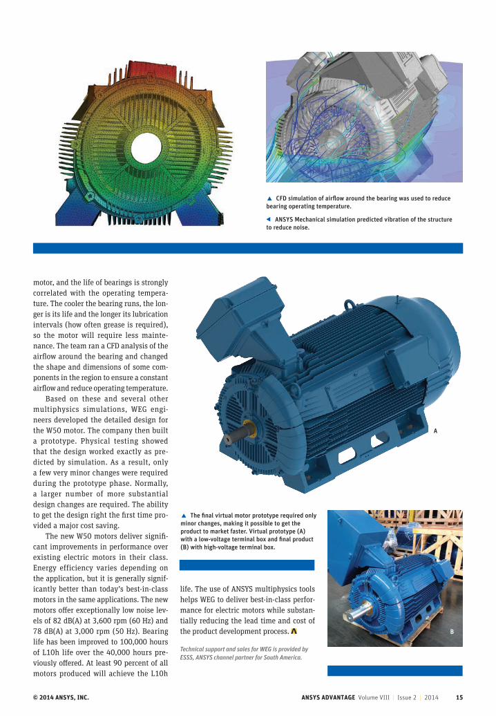
CFD simulation of airflow around the bearing was used to reduce bearing operating temperature.
ANSYS Mechanical simulation predicted vibration of the structure to reduce noise.
motor, and the life of bearings is strongly correlated with the operating tempera-ture. The cooler the bearing runs, the lon-ger is its life and the longer its lubrication intervals (how often grease is required), so the motor will require less mainte-nance. The team ran a CFD analysis of the airflow around the bearing and changed the shape and dimensions of some com-ponents in the region to ensure a constant airflow and reduce operating temperature.
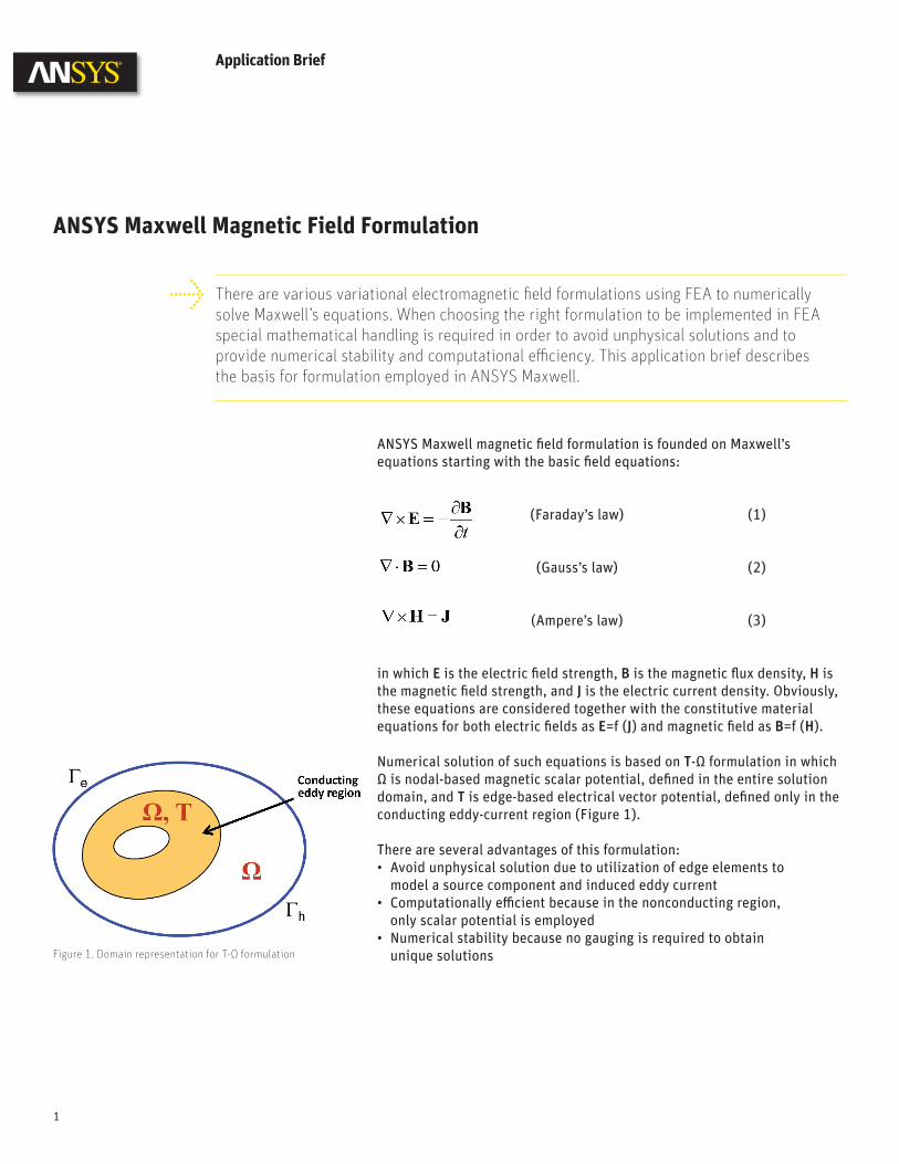
Based on these and several other multiphysics simulations, WEG engi-neers developed the detailed design for the W50 motor. The company then built a prototype. Physical testing showed that the design worked exactly as pre-dicted by simulation. As a result, only a few very minor changes were required during the prototype phase. Normally, a larger number of more substantial design changes are required. The ability to get the design right the first time pro-vided a major cost saving.
The new W50 motors deliver signifi-cant improvements in performance over existing electric motors in their class. Energy efficiency varies depending on the application, but it is generally signif-icantly better than today’s best-in-class motors in the same applications. The new motors offer exceptionally low noise lev-els of 82 dB(A) at 3,600 rpm (60 Hz) and 78 dB(A) at 3,000 rpm (50 Hz). Bearing life has been improved to 100,000 hours of L10h life over the 40,000 hours pre-viously offered. At least 90 percent of all motors produced will achieve the L10h
life. The use of ANSYS multiphysics tools helps WEG to deliver best-in-class perfor-mance for electric motors while substan-tially reducing the lead time and cost of the product development process.
Technical support and sales for WEG is provided by ESSS, ANSYS channel partner for South America.
The final virtual motor prototype required only minor changes, making it possible to get the product to market faster. Virtual prototype (A) with a low-voltage terminal box and final product (B) with high-voltage terminal box.
A
B
ANSYS Maxwell magnetic fi eld formulation is founded on Maxwell’s equations starting with the basic fi eld equations:
(Faraday’s law) (1)
(Gauss’s law) (2)
(Ampere’s law) (3)
in which E is the electric fi eld strength, B is the magnetic fl ux density, H is the magnetic fi eld strength, and J is the electric current density. Obviously, these equations are considered together with the constitutive material equations for both electric fi elds as E=f (J) and magnetic fi eld as B=f (H).
Numerical solution of such equations is based on T-Ω formulation in which Ω is nodal-based magnetic scalar potential, defi ned in the entire solution domain, and T is edge-based electrical vector potential, defi ned only in the conducting eddy-current region (Figure 1). There are several advantages of this formulation:• Avoid unphysical solution due to utilization of edge elements to
model a source component and induced eddy current• Computationally effi cient because in the nonconducting region,
only scalar potential is employed• Numerical stability because no gauging is required to obtain
unique solutions
Application Brief
ANSYS Maxwell Magnetic Field Formulation
There are various variational electromagnetic fi eld formulations using FEA to numerically solve Maxwell’s equations. When choosing the right formulation to be implemented in FEA special mathematical handling is required in order to avoid unphysical solutions and to provide numerical stability and computational effi ciency. This application brief describes the basis for formulation employed in ANSYS Maxwell.
1
Figure 1. Domain representation for T-Ω formulation
In T-Ω formulation, the key to allow the use of scalar potential is that the solution domain has to be single connected. In the eddy-conducting region, fi eld H is described by both electrical vector potential T and magnetic sca-lar potential Ω, and curl of the electrical vector potential T is the induced eddy-current density. In the source conductor region, fi eld H is described by both applied source fi eld Hp and magnetic scalar potential Ω, in which curl of Hp is the source current density J. In the non-source, non-eddy-conductor region, since 0=×∇ H and curl of any gradient is always zero, then H can be represented by the gradient of the magnetic scalar potential as long as the domain is single connected.
To make the domain single connected, you need to introduce a cut so that Ampere’s law can hold with respect to T in the cut region. This means in the nonconducting cut region, even though there is no current, fi eld H is also described by both Ω and T, not just by Ω alone.
Therefore, for the T-Ω formulation with multiple connected domains, you identify the nonconducting cut domain. In ANSYS Maxwell, the process of cut domain generation is automatically done based on the automatic identi-fi cation of tree and cotree algorithm (Figure 2). Case StudyThis case study illustrates the automatic creation of a cut domain for a one-phase winding in a three-phase synchronous generator with damper. The one-phase winding is colored brown (Figure 3), and the automatically identifi ed cut represented by one layer of elements is blue. Taking advan-tage of the periodic boundary condition, only one quarter is modeled. For the damper with induced eddy current, a total of 16 cuts are automatically identifi ed, which precisely matches the number of 16 holes; even one hole is cut into two halves by the master/slave boundary (Figure 4).
ANSYS Maxwell Magnetic Field Formulation
2
Figure 2. Identifi cation of multiple connected region and creation of cutting domain are all done automatically based on tree/cotree technology.
Figure 3. Quarter model of three-phase synchronous generator with damper
Figure 4. Magnetic fl ux density (left) and eddy-current distribution on damper (right), 16 cuts

When rigid motion is involved in magnetic transient analysis, two indepen-dent meshes must be coupled together after an arbitrary displacement of the moving part. To achieve maximum fl exibility, non-conforming meshes are used for the coupling (Figure 5). This means that the scalar potential at each node, the vector fi eld at each edge on the slave coupling surface, has to be mapped onto the master coupling surface to eliminate all unknowns on the slave surface.
For mapping a vector fi eld, the process of splitting slave edge variables with respect to the trace of the master mesh while preserving valid cut-ting domains is very complicated. To overcome this diffi culty, a separation technique is introduced to confi ne each cut generated to either the station-ary or moving part without crossing the coupling interface. As a result, the process of mapping the vector fi eld is completely avoided, and only the node-based scalar potential is involved in the coupling.
ANSYS Maxwell Magnetic Field Formulation
Figure 5. Moving mesh coupling technology
ANSYS, Inc. is one of the world’s leading engineering simulation software provid-ers. Its technology has enabled customers to predict with accuracy that their prod-uct designs will thrive in the real world. The companyoff ers a common platform of fully integrated multiphysics software tools designed to optimize product develop-ment processes for a wide range of industries, including aerospace, automotive, civil engineering, consumer products, chemical process, electronics, environ-mental, healthcare, marine, power, sports and others. Applied to design concept, fi nal-stage testing, validation and trouble-shooting existing designs, software from ANSYS can signifi cantly speed design and development times, reduce costs, and provide insight and understanding into product and process performance.Visit www.ansys.com for more information.
ANSYS, Inc.Southpointe275 Technology DriveCanonsburg, PA [email protected]
© 2013 ANSYS, Inc. All Rights Reserved.
There is a clear global demand for a comprehensive design methodology to support these new applications and satisfy power efficiency requirements. Most research efforts to improve motor design have focused on the motor, rather than the motor-driven system as a whole. Engineers are forced to use a host of often incompatible simulation tools to address the various levels of motor and drive systems, leading to errors and delays in the design cycle or increased cost due to build-and-test iterations. ANSYS® multiphysics and multi-scale system engineering technology is ideal to meet these challenges.
Unique Solution Several calculation techniques are available to predict electric machine performance, including classical closed-form analytical analysis, lumped parameter models based on determination of detailed parameters from finite element analysis, and nonlinear time-domain finite element analysis. Each method has advantages and disadvantages. Selecting the best method can be difficult because it requires the user to understand the differences among calculation methods. The fundamental issue differentiating these methods is the trade-off among model complexity, accuracy and computing time. Engineers use a combination of these calculation techniques as the optimal solution to simulate electric machine performance.
Success in using any simulation software is usability. Ease of use plays a significant role in speeding time to market, because engineers will quickly discard software that is difficult to use or requires in-depth knowledge of numerical simulation techniques. Launching a product quickly requires sim-ulation software that serves a number of purposes: accurate and suitable for use throughout an organization at different stages of the design process by engineers with various levels of knowledge in numerical simulation.
Electric Machine Design Methodology: A Revolutionary Approach
Electric machines are used in novel applications around the world, driven by the need for greater power efficiency in the transportation, aerospace and defense, and industrial automa-tion industries. The automotive sector focuses on the need for hybrid and electric vehicle technology to meet stringent miles-per-gallon standards. The aerospace and defense industry concentrates on replacing existing aircraft power transfer technologies (such as the central hydraulic system) with fault-tolerant electric power, in which major subsystems — including engine starting, primary flight control actuation, pumps and braking — are controlled and driven electronically. In the United States’ industrial sector, more than 40 million electric motors convert electricity into useful work in manufacturing operations. Industry spends over $30 billion (US) annually on electricity dedicated to electric motor-driven systems that drive pumps, fan and blower systems, and air compression.
1
Figure 2. Optimum electromagnetics design flow
Figure 1. Multiphysics and multi-domain electric machine design flow
Electric Machine Design Methodology: A Revolutionary Approach
The ANSYS electric machine design solution is unique in the simulation industry:• Employs the most efficient numerical techniques• Provides highly accurate, comprehensive multiphysics simulation
design of an electric machine• Includes distributed parametric analysis and HPC for robust design• Enables power electronics and embedded control software to be
simulated with a detailed finite element model
Workflow The ANSYS integrated electric machine design methodology enables users to design, analyze and deliver efficient, optimized electric machine and drive designs. The design methodology encompasses a number of ANSYS software programs that address the many design variables involved with creating such a system.
Figure 1 shows the main design flow. The initial design stage is addressed with ANSYS RMxprt™. This specialized software allows users to quickly create a geometric model of the machine from a template-based interface, calculate its performance, and make sizing decisions. Once the initial design is completed, RMxprt creates the complete setup of the 2-D/3-D magnetic design in ANSYS Maxwell®.
Maxwell can execute rigorous performance calculations of the machine, including the motion-induced physics caused by linear translational and rotational motion, advanced hysteresis analysis, demagnetization of per-manent magnets and other critical electromagnetic machine parameters. Maxwell is integrated into ANSYS Workbench™, where it can share the same CAD source with other ANSYS physics-based solvers and couple with ANSYS Mechanical™, ANSYS Fluent® or ANSYS Icepak®.
Workbench also links Maxwell to the system design optimization capability provided by ANSYS DesignXplorer™ software.
Figure 2 illustrates the optimum design scheme employed, based exclu-sively on the electromagnetic design flow. Narrowing the design space with RMxprt, the magnetic transient design setup is automatically generated as either 2-D or 3-D designs. The benefit of 2-D symmetry is due to the radial magnetic field topology for most electrical machines. However, axial field or transversal field topologies require 3-D designs. Nevertheless, for ac-curacy reasons, 3-D designs are required even if radial field topologies are considered whenever the user employs end effects, multi-axial segmented permanent magnets or skewing topologies. Although Maxwell software is a general FEA tool, its capabilities enable users to customize and apply very specific analyses for electrical machines, such as D-Q solution computation (Figure 3). Maxwell also enables users to employ even-more complex algo-rithms as maximum torque per ampere unit (MTPA) control strategy (Figure 4) to compute efficiency maps (Figure 5).
2
Figure 3. D-Q solution for interior permanent magnet machine design
Figure 4. Maximum torque per ampere unit
Figure 5. Electric machine efficiency map

Electric Machine Design Methodology: A Revolutionary Approach
Design optimization of interior permanent magnet (IPM) machines is complicated by the fact that the maximum torque production is a function of the advance angle of the current, which, in turn, is a function of design parameters. This means that for a systematic comparison of candidate designs, a search/optimization of the optimum operating point (MTPA) has to be performed for every candidate design. The multi-objective definition can be summarized as follows: minimize torque ripple and total losses (core and copper) while maximizing torque production per unit volume at rated load.
Within ANSYS Workbench (Figure 6), ANSYS Mechanical’s stress, thermal, CFD and acoustic solvers provide important multiphysics capabilities required for detailed analysis of the electric machine. Losses calculated by Maxwell can be used as inputs to the thermal or CFD solver to calculate the machine’s temperature distribution (Figure 7) and to evaluate cooling strat-egies. Electromagnetic forces and torque calculated in Maxwell are used as inputs to the stress solver to analyze deformations and further assess potential vibrations (Figure 8).
Once the machine is designed, the Maxwell model can be integrated into ANSYS Simplorer® (Figure 9). Simplorer is a multi-domain circuit and system simulator for designing high-performance systems. At this stage, the objective is to validate the electric machine works with the electric drive and digital control system. Simplorer unites circuit simulation with block diagrams, state machines and VHDL-AMS to add power electronic circuits and controls to the motor model created by Maxwell. Additionally, the embedded software of the digital control can be incorporated through cosimulation with the Esterel SCADE suite (Figure 10).
The capability to simulate these highly complex systems at various levels of abstraction is another distinguishing feature of the ANSYS integrated electric machine design methodology.
ConclusionThe ANSYS robust electrical machine and drive design approach delivers the computational power and ease of use demanded by today’s overloaded engineers. The main benefit customers receive by using ANSYS solutions is increased productivity from engineering teams, which results in:• Shorter time to market• Comprehensive multiphysics from a single vendor• Robust design and optimization• Ability to validate all aspects of the system (electric machine, power
electronics, control, embedded software) prior to prototyping
3
Figure 7. Averaged power loss (left) computed in ANSYS Maxwell generates thermal distribution computed in ANSYS Fluent (right) accounting for fluid dynamics.
Figure 8. Vibration and acoustic noise analysis workflow
Figure 6. ANSYS Workbench coupling capabilities
4

Design Challenges and RequirementsThe established design fl ow responds to the challenges in hybrid electric technology innovation:• Shorter design cycle - Industry innovations occur at a rapid pace and competition is fi erce• Increasing battery complexity - 3 million element cell model - Entire pack thermal model ~ 500 million cells, calling for meshing and
simulating complex geometries accurately and quickly• Increased performance - Maximize range - Maximize fuel effi ciency - Maximize power delivery and power management; power available
rapidly decreases with lower cell temperature• Increased safety - Heating/cooling system of the pack ensures cell temperature to be
lower than the maximum allowed value under all vehicle operating and ambient conditions to prevent thermal runaway
• Increased lifespan - Heating/cooling system of the pack maintains as constant-as-possible
cell temperature of 30 C under all vehicle operating and ambient conditions
White Paper
End-To-End Cell–Pack–System Solution: Rechargeable Lithium-Ion Battery
Industry has become more interested in developing optimal energy storage systems as a result of increasing gasoline prices and environmental concerns. A major application for energy stor-age use is hybrid electric vehicles (HEVs) and electric vehicles (EVs). The rechargeable energy storage system is a key design issue, as it dominates overall vehicle performance. The system as a whole must deliver high performance in terms of energy density and power management throughout a variety of driving profi les. The batteries are key elements in sustaining power and energy requirements of the system. However, in many applications the required power and thermal management are key factors for battery sizing. Thermal stability, charge capabili-ties, lifecycle and cost are also important considerations during the system design process.
ANSYS helps engineers deliver hybrid electric vehicle innovation through end-to-end cell–pack–system simulation that includes multiple physics (electrochemistry, electrical, electron-ics, thermal, fl uidic) and controls (embedded software). A simulation-based approach enables designers to achieve shorter design cycles and optimize battery performance, safety and lifespan.
1

End-To-End Cell–Pack–System Solution: Rechargeable Lithium-Ion Battery
Multiscale Lithium-Ion Battery ModelingA complete lithium-ion (li-ion) battery simulation employs not just multiple physics domains to achieve accurate performance prediction but also a de-tailed multiscale design concept to transfer model data from molecular lev-el to electrode level and, furthermore, to cell and module simulation levels (Figure 1). The ultimate goal of this comprehensive simulation environment is to integrate multi-module-level information into the powertrain system to evaluate overall performance of hybrid or electric vehicle technology.
Electrode LevelAt the electrode level, the electrochemistry is the physical domain that explains the solid electrolyte interface formation and generates appropriate cell model information (Figure 2).
A commonly used physics-based electrochemistry model for a lithium-ion battery cell was fi rst proposed by Professor Newman in 1993 (Doyle, Fuller, & Newman, 1993). The model consists of a tightly coupled set of partial diff erential equations. The method has become known as pseudo 2-D in literature due to the 2-D implementation of particle modeling. Numerically obtaining a solution to the full 2-D implementation turns out to be chal-lenging even for commercial software due to the tight coupling between equations. Therefore, a novel 1-D approach is used and implemented in the VHDL-AMS language for further circuit and system simulations.
Figure 1. Total li-ion battery simulation solution
Figure 2. Schematic of lithium-ion battery cell
2
The model shown in Figure 3 is based on:• Electrochemical kinetics• Solid-state li transport• Electrolytic li transport• Charge conservation/transport• (Thermal) energy conservation
The concentration equation in a form ready for fi nite volume approach is
(1)
The governing equation for i2 in the negative electrode is
(2)The governing equation for ϕ2 in the negative electrode is
(3)
The governing equation for ϕ1 in the negative electrode is
(4)
The governing equation for concentration in particles cs is
(5)
Note that a mix of fi nite diff erence and fi nite volume methods is used to solve the set of equations. More specifi cally, the fi nite volume method is used for the conserved quantities of i2, c and cs, but the fi nite diff erence method is used for potential ϕ1 and ϕ2, which are not conserved quantities. Figure 4 shows a representative mesh for the negative electrode used for the lithium-ion cell electrochemical model. The six dots represent nodes for the fi nite diff erence approach, and the fi ve squares represent control volumes for the fi nite volume approach. The arrows between the particle control volumes and main control volumes represent the mass exchange between particles and the main domain due to the Butler–Volmer equation (Bard & Faulkner, 2001) (or chemical reaction occurring at the surface of the particles).
Figure 3. Newman electrochemistry model
Figure 4. Cell-level design
3
End-To-End Cell–Pack–System Solution: Rechargeable Lithium-Ion Battery

Cell LevelDetailed design simulation at the cell level uses computational fl uid dynamics (CFD) analysis.
CFD can be used for battery thermal management analysis; however, CFD tools can be expensive for large systems-level transient analysis. Due to the size of the CFD models, the simulation software can be cumbersome to couple with an electrical circuit model for large system analysis.
The ANSYS solution for systems-level simulation design incorporates reduced-order models suitable for systems-level transient analysis. The well-known thermal network is one option. Figure 5 shows an example of a thermal network. To apply such a model, one builds thermal nodes, each associated with a thermal capacitor representing the heat capacity at that node. Nodes are connected using thermal resistors representing heat conduction to and from that node. The model has limited accuracy because, in general, one cannot aff ord too many nodes: A large number of thermal nodes increases the complexity and thus defeats the very purpose of using a circuit-equivalent model. The equivalent thermal model obtained needs careful calibration and calculation of thermal resistance and capacitance.
Another approach uses linear time invariant (LTI) characterization. In this method, an RC network is used; however, these RC elements serve a diff er-ent purpose. In the LTI method, RCs are used to match the transfer function of the system. The method has a fi xed RC topology as opposed to diff erent topologies used in a thermal network. Such a fi xed topology makes the network generation process easy and automatic. The LTI method can be as accurate as CFD results, and there is no need to calculate thermal resis-tance and capacitance. Unlike with the thermal network, the LTI method relies on linearity and time invariance of the system, as shown in Figure 6.
Figure 5. Reduced-order thermal model based on RC thermal network
Figure 6. LTI method used to extract thermal reduced model from CFD solution
So, in this sense, although the LTI method is less general than the thermal network, for battery cooling applications it turns out that linearity and time invariance conditions can be satisfi ed or relaxed. Therefore, the battery cooling application can benefi t from this less general but otherwise much more accurate and easier approach (Hu, Stanton, Cai, & White, 2012).
4
End-To-End Cell–Pack–System Solution: Rechargeable Lithium-Ion Battery
The electrical behavior of the cell model is obtained by extracting a set of input parameters for an equivalent circuit model (ECM). Figure 7 shows a newly implemented battery ECM model extraction fl ow.
To use the ECM model, the designer starts with some test data for a cell, namely open circuit potential versus state of charge (SOC) and transient potential under pulse discharge. The ECM extraction tool kit in ANSYS® Simplorer® takes the test data and creates the cell ECM model automati-cally. Once the ECM model for a cell is created, the user has the option to connect multiple cells by drag and drop to create a battery module or pack circuit model, as illustrated in Figure 7. This model then can be used to pre-dict battery module or pack electrical performance. The validation shows that the battery ECM models give a peak error less than 0.2 percent.
Figure 7. Equivalent circuit model workfl ow
Module/Pack LevelOnce the ECM is developed, the module and the entire pack can be simu-lated at the pace of circuit simulation while preserving the accuracy of the physics-based CFD model. The major benefi t of integrating such reduced models into circuit simulation resides on the fl exibility of adding more components to the system to predict overall performance of the system. In such situations, more multiphysics analysis is required to fi t the module/pack system validation.
5
End-To-End Cell–Pack–System Solution: Rechargeable Lithium-Ion Battery

As shown in Figure 8, various bus-bar topologies are used to connect elec-tric elements within the battery module confi guration. When regulated elec-tric signals are driven from an electronic circuit unit, electromagnetic infer-ence might occur among various conductive paths, changing the conductive profi le and ultimately the power loss distribution, which has critical impact to the battery thermal management. Figure 8 shows a reduced-order model obtained from electromagnetic simulation. Electromagnetic fi eld solvers are applied to extract an electrical frequency-dependent model of the bus-bar, which can then be imported into circuit simulation environment.
The battery module dissipates heat during power consumption and during recharging. That heat causes the module to deform due to thermal expan-sion, which can result in various stresses. The power loss distribution is used to drive the thermal analysis, which in turn generates the load data to drive the total deformation simulations. Figure 9 depicts the battery module on the left, and the structural deformation on the right. This study can be used to design modules that do not exhibit excessively large defor-mations during various loads and operating conditions.
Figure 9. Thermal-stress analysis of battery module considering structural deformation
Figure 8. Battery module/pack bus-bar parasitic model
6
End-To-End Cell–Pack–System Solution: Rechargeable Lithium-Ion Battery
Complete System IntegrationComplete system simulation is the ultimate goal for a system engineer when overall performance of the powertrain is required. Before the entire integrated system is validated, the total battery model can be immediately implemented and verifi ed (as shown in Figure 10). This model couples the bus-bar, individual cell models and the LTI thermal model into a single and complete module simulation.
Figure 10. Total battery model integration into circuit design
Figure 11. End-to-end cell-pack-system HEV design fl ow
7
End-To-End Cell–Pack–System Solution: Rechargeable Lithium-Ion Battery

Figure 11 depicts the defi nition of the HEV drive train system in which the complete battery model is integrated, including embedded software control. Several other reduced-order models are included in this schematic to provide for multiphysics system simulation at the level of circuit design. This preserves the accuracy of physics-based solutions such as ANSYS Maxwell® for electric motor electromagnetic modeling, ANSYS Q3D Extractor® for parasitic extraction of frequency-dependent behavior for inverter packages and cables, ANSYS Mechanical™ for shaft and gear design models, and ANSYS Simplorer for schematic-based system design.
A suggestive example of complete system simulation of a powertrain application is shown in Figure 12. On such implementation, one can analyze in detail with a higher level of confi dence the fuel consumption at various driving profi les, monitoring battery performance at the same time.
Figure 12. Powertrain application design using ANSYS Simplorer platform
Figure 13. Fuel consumption analysis based on driving profi le
8
End-To-End Cell–Pack–System Solution: Rechargeable Lithium-Ion Battery
ConclusionThis paper discussed several challenges and simulation-based solutions for HEV and EV energy system design. Shorter time to market, increased complexity, higher performance and higher safety requirements are driving designers to apply a dynamic simulation approach. A multiscale, multi-physics simulation fl ow emphasizes comprehensive modeling and a hierar-chical method that leads to full system simulation. Modeling of the physics is performed using rigorous 3-D simulation to extract appropriate circuit- and system-level reduced-order models. These models are then combined in top-level system simulation, allowing engineers to predict details at any level in the hierarchy.
ReferencesBard, A., Faulkner, L. (2001). Electrochemical Methods. Fundamentals and Applications (2nd ed.). John Wiley and Sons, Inc.
Doyle, M., Fuller, T. F., Newman, J. (1993). Modeling of Galvanostatic Charge and Discharge of the Lithium/Polymer/Insertion Cell. TBD, 140, pp. 1526-1533.
Hu, X., Stanton, S., Cai, L., White, R. E. (2012). Model Order Reduction for Solid-Phase Diff usion in Physics-Based Lithium Ion Cell Models. J. Power Sources.
ANSYS, Inc. is one of the world’s leading engineering simulation software provid-ers. Its technology has enabled customers to predict with accuracy that their prod-uct designs will thrive in the real world. The company off ers a common platform of fully integrated multiphysics software tools designed to optimize product develop-ment processes for a wide range of industries, including aerospace, automotive, civil engineering, consumer products, chemical process, electronics, environ-mental, healthcare, marine, power, sports and others. Applied to design concept, fi nal-stage testing, validation and trouble-shooting existing designs, software from ANSYS can signifi cantly speed design and development times, reduce costs, and provide insight and understanding into product and process performance.Visit www.ansys.com for more information.
Any and all ANSYS, Inc. brand, product, service and feature names, logos and slo-gans are registered trademarks or trademarks of ANSYS, Inc. or its subsidiaries in the United States or other countries. All other brand, product, service and feature names or trademarks are the property of their respective owners.
ANSYS, Inc.Southpointe275 Technology DriveCanonsburg, PA [email protected]
© 2013 ANSYS, Inc. All Rights Reserved.
End-To-End Cell–Pack–System Solution: Rechargeable Lithium-Ion Battery

© 2014 ANSYS, INC. ANSYS ADVANTAGE Volume VIII | Issue 1 | 2014 11
ROBUST ELECTRIC MACHINE DESIGN THROUGH MULTIPHYSICS
By Cassiano A. Cezario, Briam C. Bork, Marcelo Verardi, Research and Technological Innovation Department, and José R. Santos, Product Development and Application Department, WEG Equipamentos Elétricos S.A. — Motores, Jaraguá do Sul, Brazil
Electromagnetic, mechanical and thermal simulation plus design optimization help to improve energy efficiency, noise and bearing life of robust electric motors.
ROBUST ELECTRIC MACHINE DESIGN
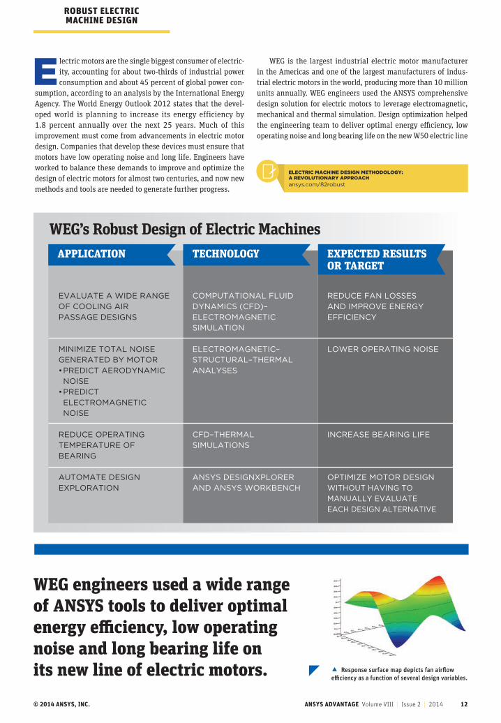
© 2014 ANSYS, INC. ANSYS ADVANTAGE Volume VIII | Issue 2 | 2014 12
WEG engineers used a wide range of ANSYS tools to deliver optimal energy efficiency, low operating noise and long bearing life on its new line of electric motors.
WEG’s Robust Design of Electric Machines
Electric motors are the single biggest consumer of electric-ity, accounting for about two-thirds of industrial power consumption and about 45 percent of global power con-
sumption, according to an analysis by the International Energy Agency. The World Energy Outlook 2012 states that the devel-oped world is planning to increase its energy efficiency by 1.8 percent annually over the next 25 years. Much of this improvement must come from advancements in electric motor design. Companies that develop these devices must ensure that motors have low operating noise and long life. Engineers have worked to balance these demands to improve and optimize the design of electric motors for almost two centuries, and now new methods and tools are needed to generate further progress.
WEG is the largest industrial electric motor manufacturer in the Americas and one of the largest manufacturers of indus-trial electric motors in the world, producing more than 10 million units annually. WEG engineers used the ANSYS comprehensive design solution for electric motors to leverage electromagnetic, mechanical and thermal simulation. Design optimization helped the engineering team to deliver optimal energy efficiency, low operating noise and long bearing life on the new W50 electric line
EVALUATE A WIDE RANGE
OF COOLING AIR
PASSAGE DESIGNS
MINIMIZE TOTAL NOISE
GENERATED BY MOTOR
• PREDICT AERODYNAMIC
NOISE
• PREDICT
ELECTROMAGNETIC
NOISE
REDUCE OPERATING
TEMPERATURE OF
BEARING
AUTOMATE DESIGN
EXPLORATION
COMPUTATIONAL FLUID
DYNAMICS (CFD)–
ELECTROMAGNETIC
SIMULATION
ELECTROMAGNETIC–
STRUCTURAL–THERMAL
ANALYSES
CFD–THERMAL
SIMULATIONS
ANSYS DESIGNXPLORER
AND ANSYS WORKBENCH
REDUCE FAN LOSSES
AND IMPROVE ENERGY
EFFICIENCY
LOWER OPERATING NOISE
INCREASE BEARING LIFE
OPTIMIZE MOTOR DESIGN
WITHOUT HAVING TO
MANUALLY EVALUATE
EACH DESIGN ALTERNATIVE
APPLICATION TECHNOLOGY EXPECTED RESULTS OR TARGET
ROBUST ELECTRIC MACHINE DESIGN
Response surface map depicts fan airflow efficiency as a function of several design variables.
ELECTRIC MACHINE DESIGN METHODOLOGY: A REVOLUTIONARY APPROACH
ansys.com/82robust

© 2014 ANSYS, INC. ANSYS ADVANTAGE Volume VIII | Issue 2 | 2014 13
of motors. The broad range of ANSYS capa-bilities was instrumental in designing and optimizing the electric motor with-out the need to individually evaluate each design alternative.
IMPROVING ENERGY EFFICIENCYLarge electric motors in the 125 horse-power to 1,750 horsepower range typ-ically have two fans: one to cool the motor interior and the other to cool its exterior. These fans consume a consid-erable amount of power, and WEG engi-neers believed that a promising approach to improving energy efficiency was to improve fan efficiency. They focused on the internal fan, particularly on reducing losses as air flows through the motor. The airflow generated by the fan flows through openings in the frame. Losses could be reduced by increasing these openings — but this strategy would reduce the motor’s electromagnetic performance.
WEG engineers used ANSYS CFD soft-ware to model the airflow through the interior of the motor. They defined key parameters, such as the openings where air passes through the frame, as para-metric dimension variables. Since many of these design parameters impact the motor’s electromagnetic performance, engineers produced an ANSYS Maxwell electromagnetic model of the motor with the same parametric variables as the CFD model. They generated a table of varying values for each of the parameters.
WEG employed ANSYS DesignXplorer to create a design of experiments (DOE) that subdivided the design space to effi-ciently explore it with a relatively small number of simulation experiments and to run multiphysics simulations with-out human intervention. Comprehensive simulation tools in the ANSYS Workbench environment and design optimization with ANSYS DesignXplorer enabled WEG
to increase the number of simulations per-formed from four per month in 2005 to 800 per month currently. High-performance computing (HPC) also helped enable this improvement. WEG uses HPC Packs for CFD, and Maxwell runs with 64 cores dis-tributed across eight workstations.
Output results for each design point were stored in a table and visualized with a response surface map that com-pletely maps out the design space. The response surface was used to graphically plot the effect of variables on fan losses. Simulations were not coupled in this case due to computing resource limitations; however, in the future, WEG will use cou-pled multiphysics simulations to even more accurately determine optimal val-ues for parametric variables by consid-ering all of the physics. WEG engineers manually compared response surface maps, plots and tables for the CFD and electromagnetic analysis to determine the
Before-and-after comparison of ANSYS CFX simulations shows improved airflow that reduces fan losses in W50 motor compared to previous-generation design.
WEG increased the number of CFD simulations performed from four per month in 2005 to 800 per month currently.
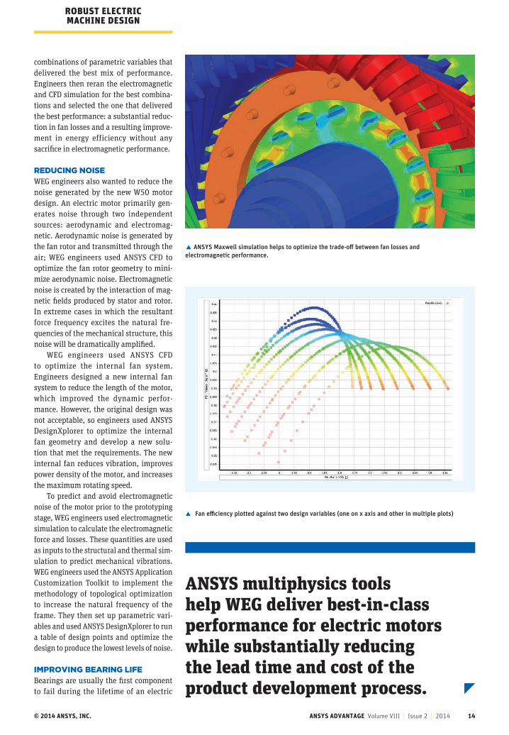
© 2014 ANSYS, INC. ANSYS ADVANTAGE Volume VIII | Issue 2 | 2014 14
ROBUST ELECTRIC MACHINE DESIGN
ANSYS multiphysics tools help WEG deliver best-in-class performance for electric motors while substantially reducing the lead time and cost of the product development process.
ANSYS Maxwell simulation helps to optimize the trade-off between fan losses and electromagnetic performance.
Fan efficiency plotted against two design variables (one on x axis and other in multiple plots)
combinations of parametric variables that delivered the best mix of performance. Engineers then reran the electromagnetic and CFD simulation for the best combina-tions and selected the one that delivered the best performance: a substantial reduc-tion in fan losses and a resulting improve-ment in energy efficiency without any sacrifice in electromagnetic performance.
REDUCING NOISEWEG engineers also wanted to reduce the noise generated by the new W50 motor design. An electric motor primarily gen-erates noise through two independent sources: aerodynamic and electromag-netic. Aerodynamic noise is generated by the fan rotor and transmitted through the air; WEG engineers used ANSYS CFD to optimize the fan rotor geometry to mini-mize aerodynamic noise. Electromagnetic noise is created by the interaction of mag-netic fields produced by stator and rotor. In extreme cases in which the resultant force frequency excites the natural fre-quencies of the mechanical structure, this noise will be dramatically amplified.
WEG engineers used ANSYS CFD to optimize the internal fan system. Engineers designed a new internal fan system to reduce the length of the motor, which improved the dynamic perfor-mance. However, the original design was not acceptable, so engineers used ANSYS DesignXplorer to optimize the internal fan geometry and develop a new solu-tion that met the requirements. The new internal fan reduces vibration, improves power density of the motor, and increases the maximum rotating speed.
To predict and avoid electromagnetic noise of the motor prior to the prototyping stage, WEG engineers used electromagnetic simulation to calculate the electromagnetic force and losses. These quantities are used as inputs to the structural and thermal sim-ulation to predict mechanical vibrations. WEG engineers used the ANSYS Application Customization Toolkit to implement the methodology of topological optimization to increase the natural frequency of the frame. They then set up parametric vari-ables and used ANSYS DesignXplorer to run a table of design points and optimize the design to produce the lowest levels of noise.
IMPROVING BEARING LIFEBearings are usually the first component to fail during the lifetime of an electric

© 2014 ANSYS, INC. ANSYS ADVANTAGE Volume VIII | Issue 2 | 2014 15
CFD simulation of airflow around the bearing was used to reduce bearing operating temperature.
ANSYS Mechanical simulation predicted vibration of the structure to reduce noise.
motor, and the life of bearings is strongly correlated with the operating tempera-ture. The cooler the bearing runs, the lon-ger is its life and the longer its lubrication intervals (how often grease is required), so the motor will require less mainte-nance. The team ran a CFD analysis of the airflow around the bearing and changed the shape and dimensions of some com-ponents in the region to ensure a constant airflow and reduce operating temperature.
Based on these and several other multiphysics simulations, WEG engi-neers developed the detailed design for the W50 motor. The company then built a prototype. Physical testing showed that the design worked exactly as pre-dicted by simulation. As a result, only a few very minor changes were required during the prototype phase. Normally, a larger number of more substantial design changes are required. The ability to get the design right the first time pro-vided a major cost saving.
The new W50 motors deliver signifi-cant improvements in performance over existing electric motors in their class. Energy efficiency varies depending on the application, but it is generally signif-icantly better than today’s best-in-class motors in the same applications. The new motors offer exceptionally low noise lev-els of 82 dB(A) at 3,600 rpm (60 Hz) and 78 dB(A) at 3,000 rpm (50 Hz). Bearing life has been improved to 100,000 hours of L10h life over the 40,000 hours pre-viously offered. At least 90 percent of all motors produced will achieve the L10h
life. The use of ANSYS multiphysics tools helps WEG to deliver best-in-class perfor-mance for electric motors while substan-tially reducing the lead time and cost of the product development process.
Technical support and sales for WEG is provided by ESSS, ANSYS channel partner for South America.
The final virtual motor prototype required only minor changes, making it possible to get the product to market faster. Virtual prototype (A) with a low-voltage terminal box and final product (B) with high-voltage terminal box.
A
B

ANSYS Electromechanical Productivity Kit ‐ Webinar
Electromagnetics And Thermal Multiphysics Analysis Webinar Click on the link to view: https://ansys.webex.com/ec0701lsp13/eventcenter/recording/recordAction.do?theAction=poprecord&
AT=pb&internalRecordTicket=4832534b00000002894c63c63763920d3ad83e877041e9429322ae41eb0f
e131ba7a02868b5a3070&renewticket=0&isurlact=true&recordID=1437552&apiname=lsr.php&format=
short&needFilter=false&&SP=EC&rID=1437552&RCID=59d43f6ccd7ce1891f63c59356581a31&siteurl=an
sys&actappname=ec0701lsp13&actname=%2Feventcenter%2Fframe%2Fg.do&rnd=7314161581&entap
pname=url0201lsp13&entactname=%2FnbrRecordingURL.do