ansteuerung eines schreib-/lesekopfs (slk) mit einem ... · vitesse de communication: 19 200 bauds....
TRANSCRIPT
Ansteuerung eines Schreib-/Lesekopfs (SLK) mit einem Mikrokontroller
Pilotage d'un Module Lecture/Ecriture (MLE) par un microcontrôleur
Controlling a Read/Write Module (RWM) by means of a micro controller
© Contrinex 2013 - JDCAPN_LF_RWM connected on uP 130118
CONTRINEX AG Industrial ElectronicsRoute André Piller 50 CH-1762 Givisiez SwitzerlandTel: +41 26 460 46 46 Fax +41 26 460 46 40 Internet: www.contrinex.com

CONTRINEX AG Industrial Electronicsroute André Piller 50 - CH 1762 Givisiez - Switzerland - Tel: +41 26 460 46 46 - Fax: +41 26 460 46 40 - Internet: www.contrinex.com - E-mail: [email protected]
RFID application note
Ansteuerung eines Schreib-/Lesekopfs (SLK) mit einem MikrokontrollerPilotage d'un Module Lecture/Ecriture (MLE) par un microcontrôleurControlling a Read/Write Module (RWM) by means of a micro controller
La présente note d'application décrit la façon de piloter un MLE au moyen d'un microcontrôleur.
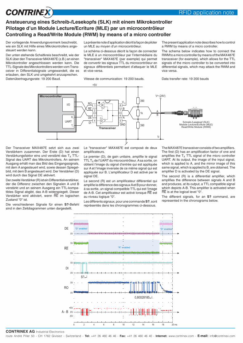
Le schéma ci-dessous décrit la façon de connecter le MLE à un microcontrôleur par l'intermédiaire du "transceiver" MAX487E (par exemple) qui permet de convertir les signaux TTL du microcontrôleur en signaux différentiels permettant d'attaquer le MLE et vice-versa.
The present application note describes how to control a RWM by means of a micro controller.
The schema below indicates how to connect the RWM to a micro controller by means of the MAX487E transceiver (for example), which allows for the TTL signals of the micro controller to be converted into differential signals, which may attack the RWM and vice versa.
Der vorliegende Anwendungsvermerk beschreibt, wie ein SLK mit Hilfe eines Mikrokontrollers ange-steuert werden kann.
Der unten stehende Schaltkreis beschreibt, wie der SLK über den Transceiver MAX487E (z.B.) an einen Mikrokontroller angeschlossen werden kann. Die TTL-Signale des Mikrokontrollers werden vom Trans-ceiver in Differentialsignale umgewandelt, die es erlauben, den SLK und umgekehrt anzusprechen.
Schreib-/Lesekopf (SLK)Module Lecture/Ecriture (MLE)
Read/Write Module (RWM)
Vitesse de communication: 19 200 bauds. Data transfer rate: 19 200 baudsDatenübertragungsrate: 19 200 Baud.
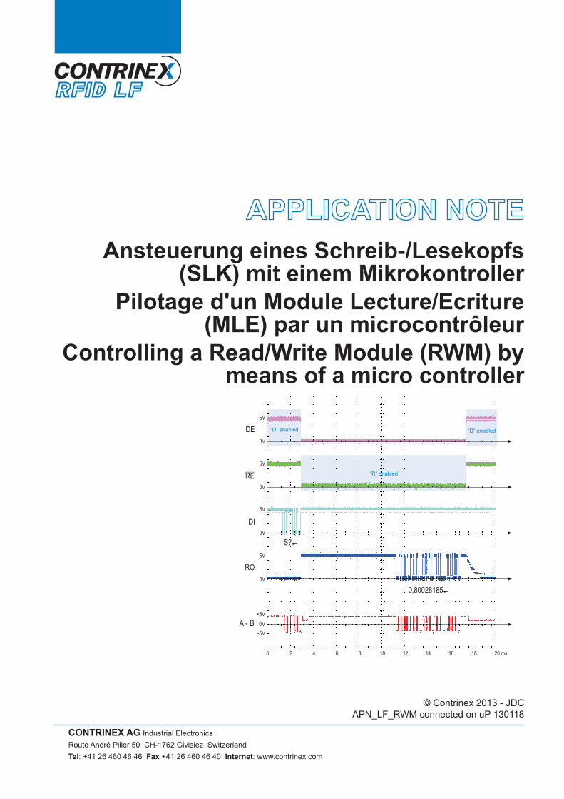
Der Transceiver MAX487E setzt sich aus zwei Verstärkern zusammen. Der Erste (D) hat einen Verstärkungsfaktor eins und verstärkt das TX TTL-Signal des UART des Mikrokontrollers. An seinem Ausgang erhält man das Bild des Eingangssignals, mit dem A angesteuert wird, sowie dessen Spiegel-bild, mit dem B angesteuert wird. Der Verstärker (D) wird durch das Signal DE aktiviert.
Der zweite Verstärker (R) ist ein Differentialverstärker, der die Differenz zwischen den Signalen A und B verstärkt und an seinem Ausgang ein TTL-kompa-tibles Signal abgibt, das A-B widerspiegelt. Dieser Verstärker wird aktiviert, wenn RE im logischen Zustand "0" ist.
Die verschiedenen Signale für einen S?-Befehl sind in den Zeitdiagrammen unten dargestellt.
Le "transceiver" MAX487E est composé de deux amplificateurs.
Le premier (D), de gain unitaire, amplifie le signal TTL TX de l'UART du microcontrôleur. A sa sortie, on obtient l'image du signal d'entrée qui est appliquée sur A et l'image inversée de ce même signal qui est appliquée sur B. L'amplificateur D est activé par le signal DE.
Le second (R) est un amplificateur différentiel qui amplifie la différence des signaux A et B pour donner, à sa sortie, un signal compatible TTL qui est l'image de A-B. Cet amplificateur est activé lorsque RE est au niveau logique "0".
Les différents signaux, pour une commande S?, sont représentés dans les chronogrammes ci-dessous.
The MAX487E transceiver consists of two amplifiers. The first (D) has an amplification factor of one and amplifies the TX TTL signal of the micro controller UART. At its output, the image of the input signal, which is applied to A, and the mirror image of this same signal, which is applied to B, are obtained. The amplifier D is activated by the DE signal.
The second (R) is a differential amplifier, which amplifies the difference between signals A and B and produces, at its output, a TTL compatible signal which depicts A-B. This amplifier is activated when RE is at the logical level "0".
The different signals, for an S? command, are represented in the chronograms below.
CONTRINEX AG Industrial Electronicsroute André Piller 50 - CH 1762 Givisiez - Switzerland - Tel: +41 26 460 46 46 - Fax: +41 26 460 46 40 - Internet: www.contrinex.com - E-mail: [email protected]
RFID application note
MLE sur uP.indd / rev. 0 / 07.06.25 - JDC
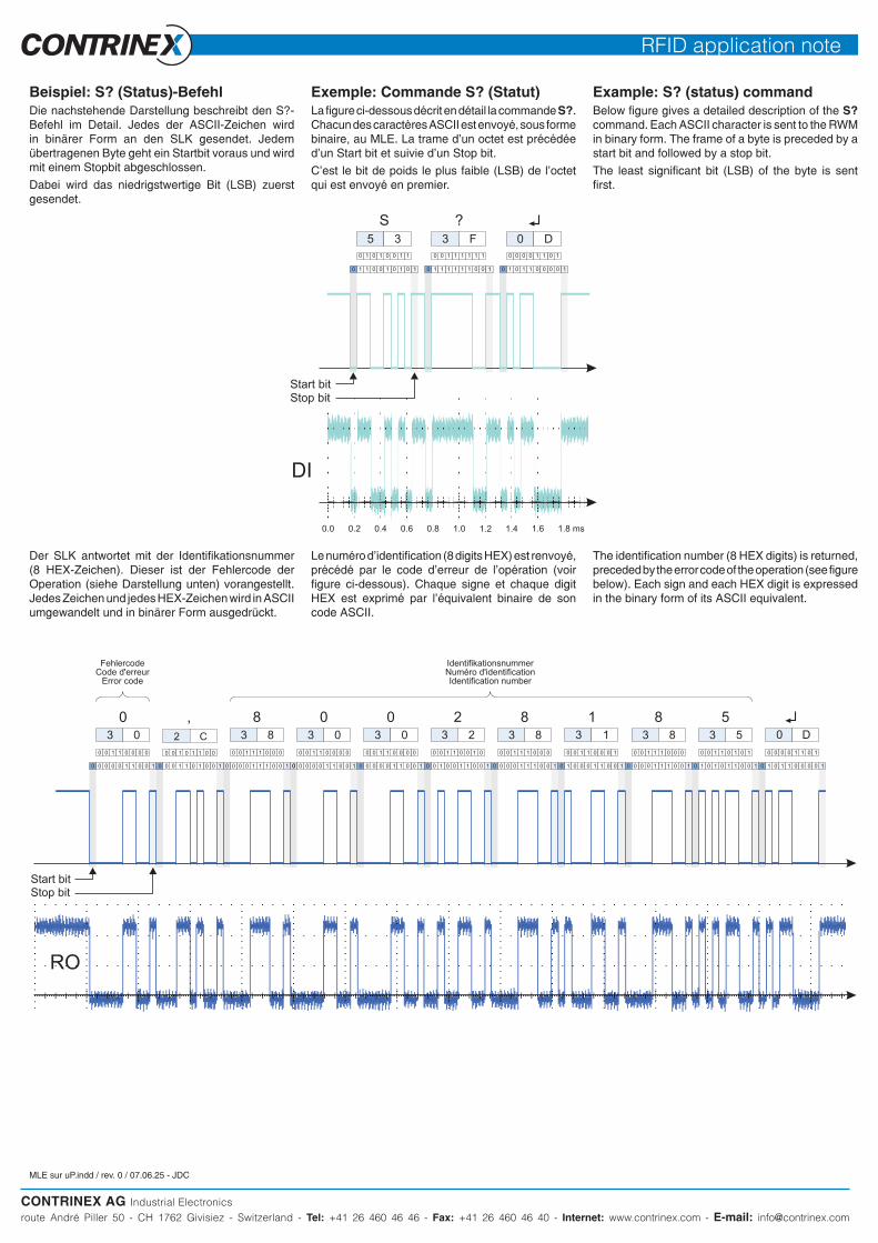
Exemple: Commande S? (Statut)La figure ci-dessous décrit en détail la commande S?. Chacun des caractères ASCII est envoyé, sous forme binaire, au MLE. La trame d'un octet est précédée d'un Start bit et suivie d'un Stop bit.
C'est le bit de poids le plus faible (LSB) de l'octet qui est envoyé en premier.
Example: S? (status) commandBelow figure gives a detailed description of the S? command. Each ASCII character is sent to the RWM in binary form. The frame of a byte is preceded by a start bit and followed by a stop bit.
The least significant bit (LSB) of the byte is sent first.
Beispiel: S? (Status)-BefehlDie nachstehende Darstellung beschreibt den S?-Befehl im Detail. Jedes der ASCII-Zeichen wird in binärer Form an den SLK gesendet. Jedem übertragenen Byte geht ein Startbit voraus und wird mit einem Stopbit abgeschlossen.
Dabei wird das niedrigstwertige Bit (LSB) zuerst gesendet.
Le numéro d'identification (8 digits HEX) est renvoyé, précédé par le code d'erreur de l'opération (voir figure ci-dessous). Chaque signe et chaque digit HEX est exprimé par l'équivalent binaire de son code ASCII.
The identification number (8 HEX digits) is returned, preceded by the error code of the operation (see figure below). Each sign and each HEX digit is expressed in the binary form of its ASCII equivalent.
Der SLK antwortet mit der Identifikationsnummer (8 HEX-Zeichen). Dieser ist der Fehlercode der Operation (siehe Darstellung unten) vorangestellt. Jedes Zeichen und jedes HEX-Zeichen wird in ASCII umgewandelt und in binärer Form ausgedrückt.
FehlercodeCode d'erreur
Error code
IdentifikationsnummerNuméro d'identificationIdentification number