ansi-asq national accreditation · pdf filethis laboratory is accredited in accordance with...
TRANSCRIPT
This laboratory is accredited in accordance with the recognized International Standard ISO/IEC 17025:2005. This accreditation demonstrates technical competence for a defined scope and the operation of a laboratory
quality management system (refer to joint ISO-ILAC-IAF Communiqué dated April 2017).
CERTIFICATE OF ACCREDITATION ANSI-ASQ National Accreditation Board
500 Montgomery Street, Suite 625, Alexandria, VA 22314, 877-344-3044 This is to certify that
Fox Valley Metrology, Ltd. 3125 Medalist Drive Oshkosh WI 54902 has been assessed by ANAB
and meets the requirements of international standard ISO/IEC 17025:2005
and national standard ANSI/NCSL Z540-1-1994 (R2002) &
ANSI/NCSL Z540.3-2006 (R2013) while demonstrating technical competence in the fields of
TESTING AND CALIBRATION Refer to the accompanying Scope of Accreditation for information regarding the types of
calibrations and/or tests to which this accreditation applies.
ACT-1272
Certificate Number
Certificate Valid: 07/07/2017-06/15/2019 Version No. 007 Issued: 07/07/2017
Version 007
Issued: 07/07/2017 www.anab.org
Page 1 of 28
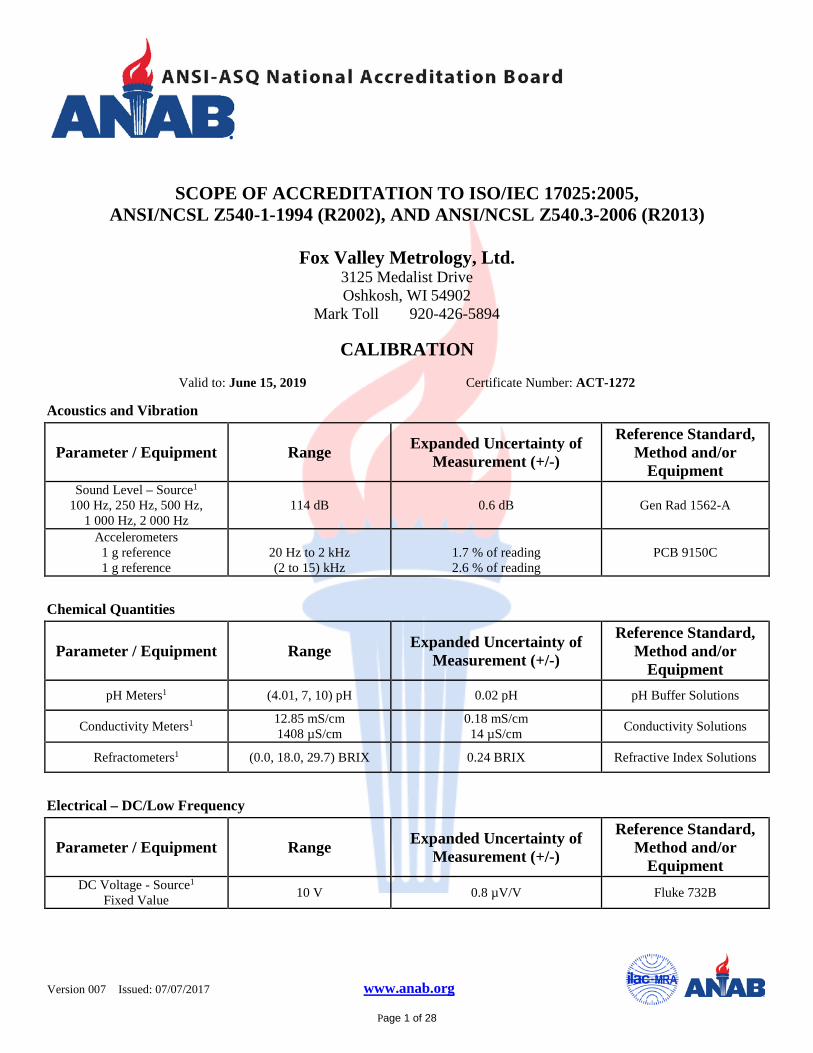
SCOPE OF ACCREDITATION TO ISO/IEC 17025:2005, ANSI/NCSL Z540-1-1994 (R2002), AND ANSI/NCSL Z540.3-2006 (R2013)
Fox Valley Metrology, Ltd.
3125 Medalist Drive Oshkosh, WI 54902
Mark Toll 920-426-5894
CALIBRATION
Valid to: June 15, 2019 Certificate Number: ACT-1272
Acoustics and Vibration
Parameter / Equipment Range Expanded Uncertainty of Measurement (+/-)
Reference Standard, Method and/or
Equipment Sound Level – Source1
100 Hz, 250 Hz, 500 Hz, 1 000 Hz, 2 000 Hz
114 dB 0.6 dB Gen Rad 1562-A
Accelerometers
1 g reference 1 g reference
20 Hz to 2 kHz (2 to 15) kHz
1.7 % of reading 2.6 % of reading
PCB 9150C
Chemical Quantities
Parameter / Equipment Range Expanded Uncertainty of Measurement (+/-)
Reference Standard, Method and/or
Equipment pH Meters1 (4.01, 7, 10) pH 0.02 pH pH Buffer Solutions
Conductivity Meters1 12.85 mS/cm 1408 µS/cm
0.18 mS/cm 14 µS/cm Conductivity Solutions
Refractometers1 (0.0, 18.0, 29.7) BRIX 0.24 BRIX Refractive Index Solutions
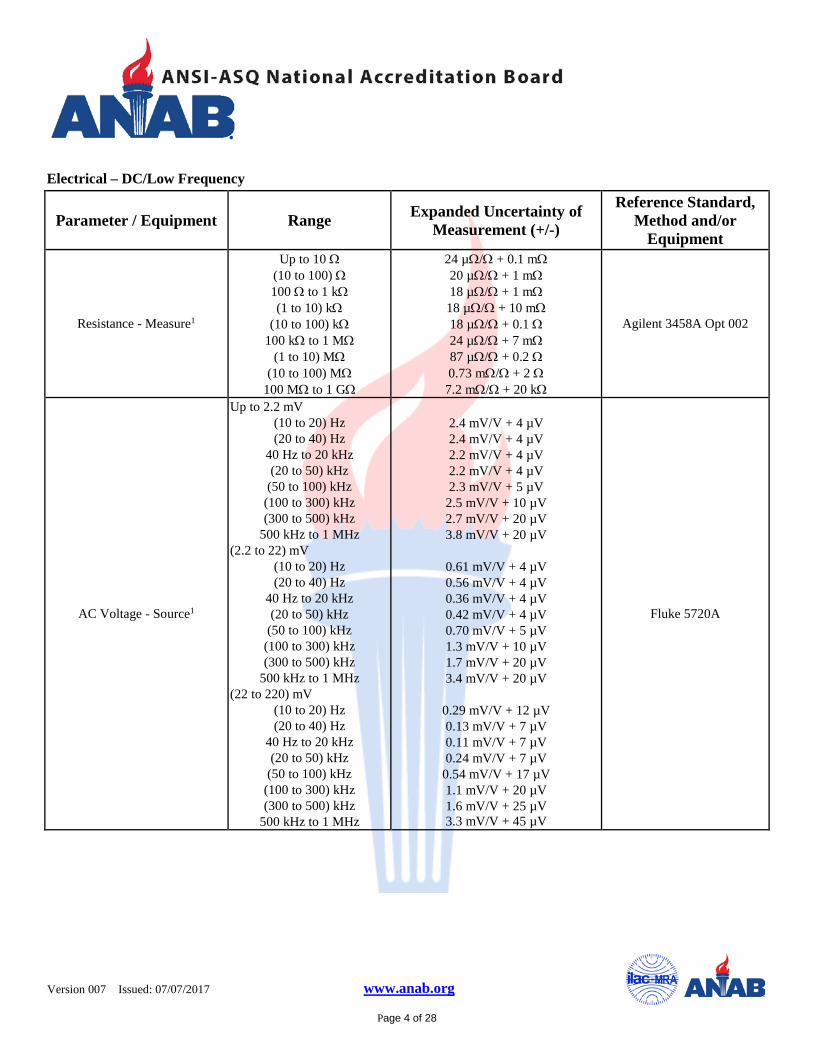
Electrical – DC/Low Frequency
Parameter / Equipment Range Expanded Uncertainty of Measurement (+/-)
Reference Standard, Method and/or
Equipment DC Voltage - Source1
Fixed Value 10 V 0.8 µV/V Fluke 732B
Version 007
Issued: 07/07/2017 www.anab.org
Page 2 of 28
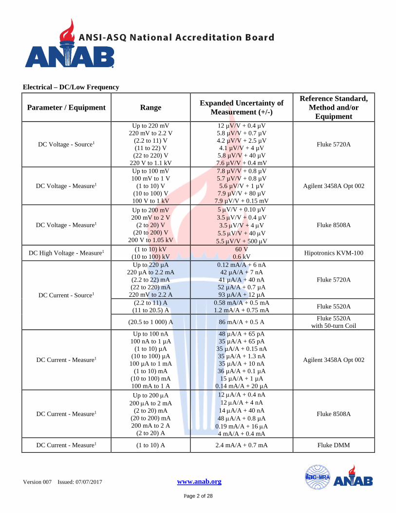
Electrical – DC/Low Frequency
Parameter / Equipment Range Expanded Uncertainty of Measurement (+/-)
Reference Standard, Method and/or
Equipment
DC Voltage - Source1
Up to 220 mV 220 mV to 2.2 V
(2.2 to 11) V (11 to 22) V (22 to 220) V
220 V to 1.1 kV
12 µV/V + 0.4 µV 5.8 µV/V + 0.7 µV 4.2 µV/V + 2.5 µV 4.1 µV/V + 4 µV
5.8 µV/V + 40 µV 7.6 µV/V + 0.4 mV
Fluke 5720A
DC Voltage - Measure1
Up to 100 mV 100 mV to 1 V
(1 to 10) V (10 to 100) V 100 V to 1 kV
7.8 µV/V + 0.8 µV 5.7 µV/V + 0.8 µV 5.6 µV/V + 1 µV
7.9 µV/V + 80 µV 7.9 µV/V + 0.15 mV
Agilent 3458A Opt 002
DC Voltage - Measure1
Up to 200 mV 200 mV to 2 V
(2 to 20) V (20 to 200) V
200 V to 1.05 kV
5 µV/V + 0.10 µV 3.5 µV/V + 0.4 µV 3.5 µV/V + 4 µV
5.5 µV/V + 40 µV 5.5 µV/V + 500 µV
Fluke 8508A
DC High Voltage - Measure1 (1 to 10) kV (10 to 100) kV
60 V 0.6 kV Hipotronics KVM-100
DC Current - Source1
Up to 220 µA 220 µA to 2.2 mA
(2.2 to 22) mA (22 to 220) mA
220 mV to 2.2 A
0.12 mA/A + 6 nA 42 µA/A + 7 nA
41 µA/A + 40 nA 52 µA/A + 0.7 µA 93 µA/A + 12 µA
Fluke 5720A
(2.2 to 11) A (11 to 20.5) A
0.58 mA/A + 0.5 mA 1.2 mA/A + 0.75 mA Fluke 5520A
(20.5 to 1 000) A 86 mA/A + 0.5 A Fluke 5520A with 50-turn Coil
DC Current - Measure1
Up to 100 nA 100 nA to 1 µA
(1 to 10) µA (10 to 100) µA
100 µA to 1 mA (1 to 10) mA
(10 to 100) mA 100 mA to 1 A
48 µA/A + 65 pA 35 µA/A + 65 pA
35 µA/A + 0.15 nA 35 µA/A + 1.3 nA 35 µA/A + 10 nA 36 µA/A + 0.1 µA 15 µA/A + 1 µA
0.14 mA/A + 20 µA
Agilent 3458A Opt 002
DC Current - Measure1
Up to 200 µA 200 µA to 2 mA
(2 to 20) mA (20 to 200) mA 200 mA to 2 A
(2 to 20) A
12 µA/A + 0.4 nA 12 µA/A + 4 nA
14 µA/A + 40 nA 48 µA/A + 0.8 µA
0.19 mA/A + 16 µA 4 mA/A + 0.4 mA
Fluke 8508A
DC Current - Measure1 (1 to 10) A 2.4 mA/A + 0.7 mA Fluke DMM
Version 007
Issued: 07/07/2017 www.anab.org
Page 3 of 28
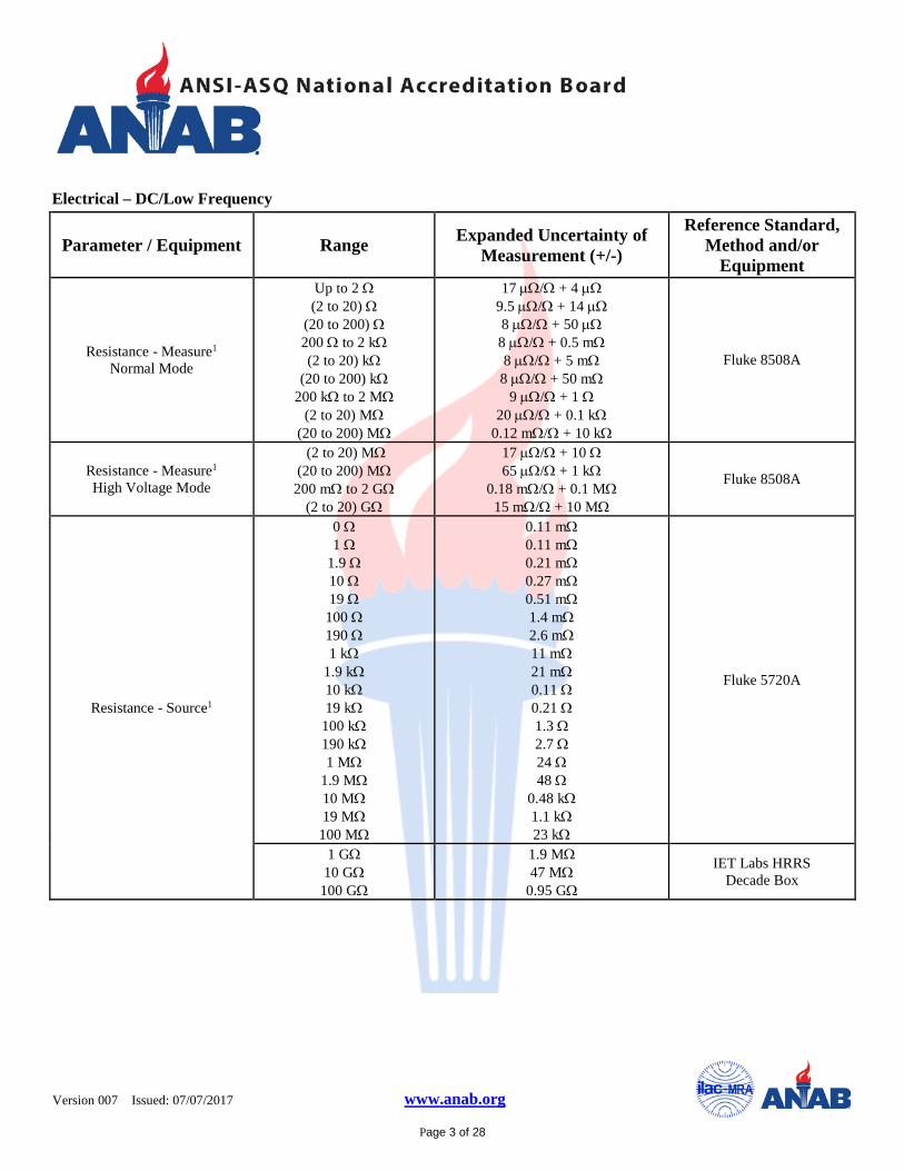
Electrical – DC/Low Frequency
Parameter / Equipment Range Expanded Uncertainty of Measurement (+/-)
Reference Standard, Method and/or
Equipment
Resistance - Measure1
Normal Mode
Up to 2 Ω (2 to 20) Ω
(20 to 200) Ω 200 Ω to 2 kΩ (2 to 20) kΩ
(20 to 200) kΩ 200 kΩ to 2 MΩ
(2 to 20) MΩ (20 to 200) MΩ
17 µΩ/Ω + 4 µΩ 9.5 µΩ/Ω + 14 µΩ 8 µΩ/Ω + 50 µΩ 8 µΩ/Ω + 0.5 mΩ 8 µΩ/Ω + 5 mΩ 8 µΩ/Ω + 50 mΩ
9 µΩ/Ω + 1 Ω 20 µΩ/Ω + 0.1 kΩ
0.12 mΩ/Ω + 10 kΩ
Fluke 8508A
Resistance - Measure1
High Voltage Mode
(2 to 20) MΩ (20 to 200) MΩ 200 mΩ to 2 GΩ
(2 to 20) GΩ
17 µΩ/Ω + 10 Ω 65 µΩ/Ω + 1 kΩ
0.18 mΩ/Ω + 0.1 MΩ 15 mΩ/Ω + 10 MΩ
Fluke 8508A
Resistance - Source1
0 Ω 1 Ω
1.9 Ω 10 Ω 19 Ω
100 Ω 190 Ω 1 kΩ
1.9 kΩ 10 kΩ 19 kΩ
100 kΩ 190 kΩ 1 MΩ
1.9 MΩ 10 MΩ 19 MΩ
100 MΩ
0.11 mΩ 0.11 mΩ 0.21 mΩ 0.27 mΩ 0.51 mΩ 1.4 mΩ 2.6 mΩ 11 mΩ 21 mΩ 0.11 Ω 0.21 Ω 1.3 Ω 2.7 Ω 24 Ω 48 Ω
0.48 kΩ 1.1 kΩ 23 kΩ
Fluke 5720A
1 GΩ 10 GΩ
100 GΩ
1.9 MΩ 47 MΩ
0.95 GΩ
IET Labs HRRS Decade Box
Version 007
Issued: 07/07/2017 www.anab.org
Page 4 of 28
Electrical – DC/Low Frequency
Parameter / Equipment Range Expanded Uncertainty of Measurement (+/-)
Reference Standard, Method and/or
Equipment
Resistance - Measure1
Up to 10 Ω (10 to 100) Ω 100 Ω to 1 kΩ (1 to 10) kΩ
(10 to 100) kΩ 100 kΩ to 1 MΩ
(1 to 10) MΩ (10 to 100) MΩ
100 MΩ to 1 GΩ
24 µΩ/Ω + 0.1 mΩ 20 µΩ/Ω + 1 mΩ 18 µΩ/Ω + 1 mΩ
18 µΩ/Ω + 10 mΩ 18 µΩ/Ω + 0.1 Ω 24 µΩ/Ω + 7 mΩ 87 µΩ/Ω + 0.2 Ω 0.73 mΩ/Ω + 2 Ω 7.2 mΩ/Ω + 20 kΩ
Agilent 3458A Opt 002
AC Voltage - Source1
Up to 2.2 mV (10 to 20) Hz (20 to 40) Hz
40 Hz to 20 kHz (20 to 50) kHz
(50 to 100) kHz (100 to 300) kHz (300 to 500) kHz
500 kHz to 1 MHz (2.2 to 22) mV
(10 to 20) Hz (20 to 40) Hz
40 Hz to 20 kHz (20 to 50) kHz
(50 to 100) kHz (100 to 300) kHz (300 to 500) kHz
500 kHz to 1 MHz (22 to 220) mV
(10 to 20) Hz (20 to 40) Hz
40 Hz to 20 kHz (20 to 50) kHz
(50 to 100) kHz (100 to 300) kHz (300 to 500) kHz
500 kHz to 1 MHz
2.4 mV/V + 4 µV 2.4 mV/V + 4 µV 2.2 mV/V + 4 µV 2.2 mV/V + 4 µV 2.3 mV/V + 5 µV
2.5 mV/V + 10 µV 2.7 mV/V + 20 µV 3.8 mV/V + 20 µV
0.61 mV/V + 4 µV 0.56 mV/V + 4 µV 0.36 mV/V + 4 µV 0.42 mV/V + 4 µV 0.70 mV/V + 5 µV 1.3 mV/V + 10 µV 1.7 mV/V + 20 µV 3.4 mV/V + 20 µV
0.29 mV/V + 12 µV 0.13 mV/V + 7 µV 0.11 mV/V + 7 µV 0.24 mV/V + 7 µV
0.54 mV/V + 17 µV 1.1 mV/V + 20 µV 1.6 mV/V + 25 µV 3.3 mV/V + 45 µV
Fluke 5720A
Version 007
Issued: 07/07/2017 www.anab.org
Page 5 of 28
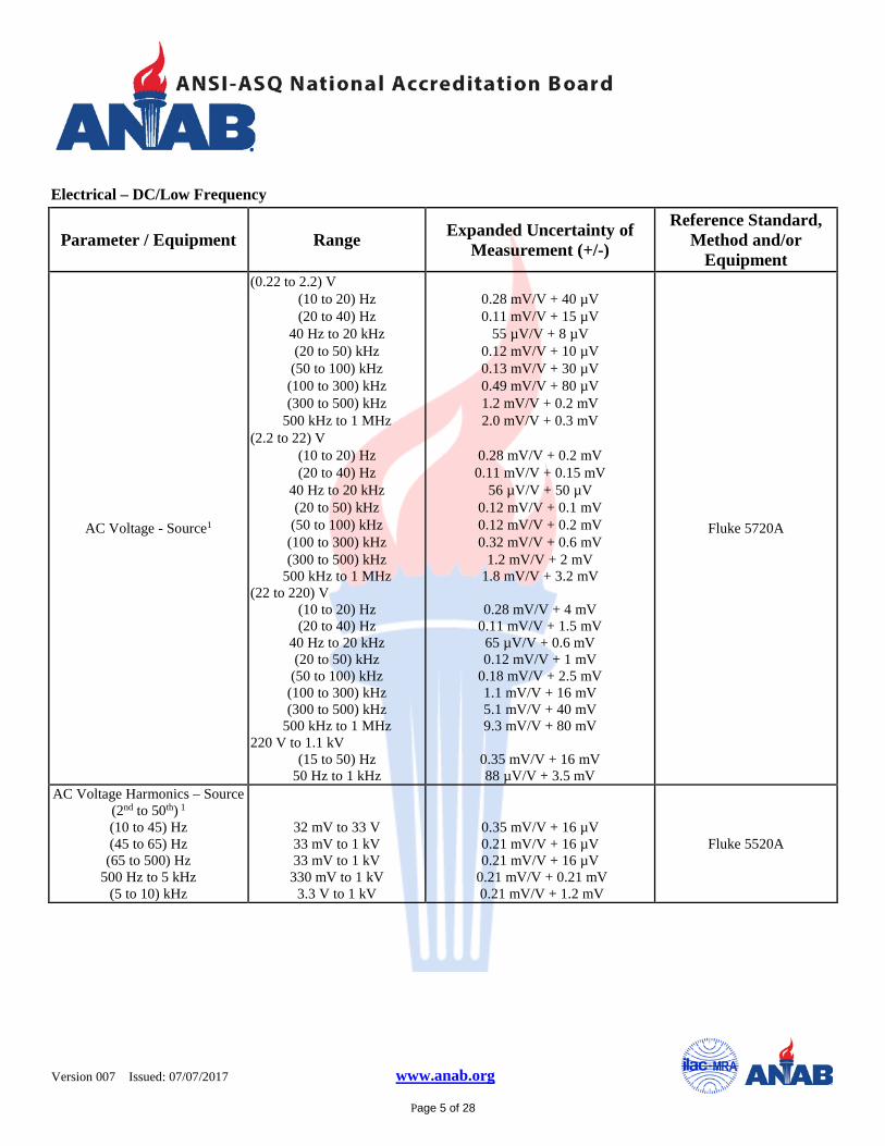
Electrical – DC/Low Frequency
Parameter / Equipment Range Expanded Uncertainty of Measurement (+/-)
Reference Standard, Method and/or
Equipment
AC Voltage - Source1
(0.22 to 2.2) V (10 to 20) Hz (20 to 40) Hz
40 Hz to 20 kHz (20 to 50) kHz
(50 to 100) kHz (100 to 300) kHz (300 to 500) kHz
500 kHz to 1 MHz (2.2 to 22) V
(10 to 20) Hz (20 to 40) Hz
40 Hz to 20 kHz (20 to 50) kHz
(50 to 100) kHz (100 to 300) kHz (300 to 500) kHz
500 kHz to 1 MHz (22 to 220) V
(10 to 20) Hz (20 to 40) Hz
40 Hz to 20 kHz (20 to 50) kHz
(50 to 100) kHz (100 to 300) kHz (300 to 500) kHz
500 kHz to 1 MHz 220 V to 1.1 kV
(15 to 50) Hz 50 Hz to 1 kHz
0.28 mV/V + 40 µV 0.11 mV/V + 15 µV
55 µV/V + 8 µV 0.12 mV/V + 10 µV 0.13 mV/V + 30 µV 0.49 mV/V + 80 µV 1.2 mV/V + 0.2 mV 2.0 mV/V + 0.3 mV
0.28 mV/V + 0.2 mV 0.11 mV/V + 0.15 mV
56 µV/V + 50 µV 0.12 mV/V + 0.1 mV 0.12 mV/V + 0.2 mV 0.32 mV/V + 0.6 mV
1.2 mV/V + 2 mV 1.8 mV/V + 3.2 mV
0.28 mV/V + 4 mV
0.11 mV/V + 1.5 mV 65 µV/V + 0.6 mV 0.12 mV/V + 1 mV
0.18 mV/V + 2.5 mV 1.1 mV/V + 16 mV 5.1 mV/V + 40 mV 9.3 mV/V + 80 mV
0.35 mV/V + 16 mV 88 µV/V + 3.5 mV
Fluke 5720A
AC Voltage Harmonics – Source (2nd to 50th) 1 (10 to 45) Hz (45 to 65) Hz
(65 to 500) Hz 500 Hz to 5 kHz
(5 to 10) kHz
32 mV to 33 V 33 mV to 1 kV 33 mV to 1 kV
330 mV to 1 kV 3.3 V to 1 kV
0.35 mV/V + 16 µV 0.21 mV/V + 16 µV 0.21 mV/V + 16 µV
0.21 mV/V + 0.21 mV 0.21 mV/V + 1.2 mV
Fluke 5520A
Version 007
Issued: 07/07/2017 www.anab.org
Page 6 of 28
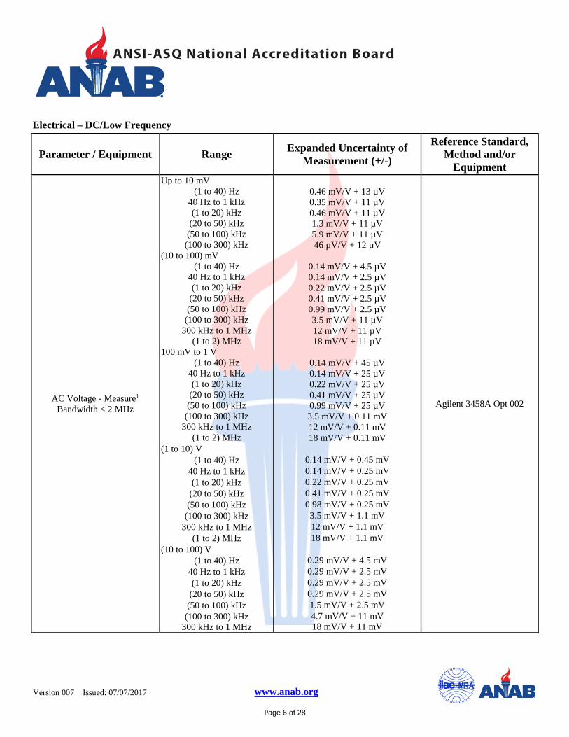
Electrical – DC/Low Frequency
Parameter / Equipment Range Expanded Uncertainty of Measurement (+/-)
Reference Standard, Method and/or
Equipment
AC Voltage - Measure1 Bandwidth < 2 MHz
Up to 10 mV (1 to 40) Hz
40 Hz to 1 kHz (1 to 20) kHz
(20 to 50) kHz (50 to 100) kHz
(100 to 300) kHz (10 to 100) mV
(1 to 40) Hz 40 Hz to 1 kHz (1 to 20) kHz
(20 to 50) kHz (50 to 100) kHz
(100 to 300) kHz 300 kHz to 1 MHz
(1 to 2) MHz 100 mV to 1 V
(1 to 40) Hz 40 Hz to 1 kHz (1 to 20) kHz
(20 to 50) kHz (50 to 100) kHz
(100 to 300) kHz 300 kHz to 1 MHz
(1 to 2) MHz (1 to 10) V
(1 to 40) Hz 40 Hz to 1 kHz (1 to 20) kHz
(20 to 50) kHz (50 to 100) kHz
(100 to 300) kHz 300 kHz to 1 MHz
(1 to 2) MHz (10 to 100) V
(1 to 40) Hz 40 Hz to 1 kHz (1 to 20) kHz
(20 to 50) kHz (50 to 100) kHz
(100 to 300) kHz 300 kHz to 1 MHz
0.46 mV/V + 13 µV 0.35 mV/V + 11 µV 0.46 mV/V + 11 µV 1.3 mV/V + 11 µV 5.9 mV/V + 11 µV 46 µV/V + 12 µV
0.14 mV/V + 4.5 µV 0.14 mV/V + 2.5 µV 0.22 mV/V + 2.5 µV 0.41 mV/V + 2.5 µV 0.99 mV/V + 2.5 µV 3.5 mV/V + 11 µV 12 mV/V + 11 µV 18 mV/V + 11 µV
0.14 mV/V + 45 µV 0.14 mV/V + 25 µV 0.22 mV/V + 25 µV 0.41 mV/V + 25 µV 0.99 mV/V + 25 µV 3.5 mV/V + 0.11 mV 12 mV/V + 0.11 mV 18 mV/V + 0.11 mV
0.14 mV/V + 0.45 mV 0.14 mV/V + 0.25 mV 0.22 mV/V + 0.25 mV 0.41 mV/V + 0.25 mV 0.98 mV/V + 0.25 mV 3.5 mV/V + 1.1 mV 12 mV/V + 1.1 mV 18 mV/V + 1.1 mV
0.29 mV/V + 4.5 mV 0.29 mV/V + 2.5 mV 0.29 mV/V + 2.5 mV 0.29 mV/V + 2.5 mV 1.5 mV/V + 2.5 mV 4.7 mV/V + 11 mV 18 mV/V + 11 mV
Agilent 3458A Opt 002
Version 007
Issued: 07/07/2017 www.anab.org
Page 7 of 28
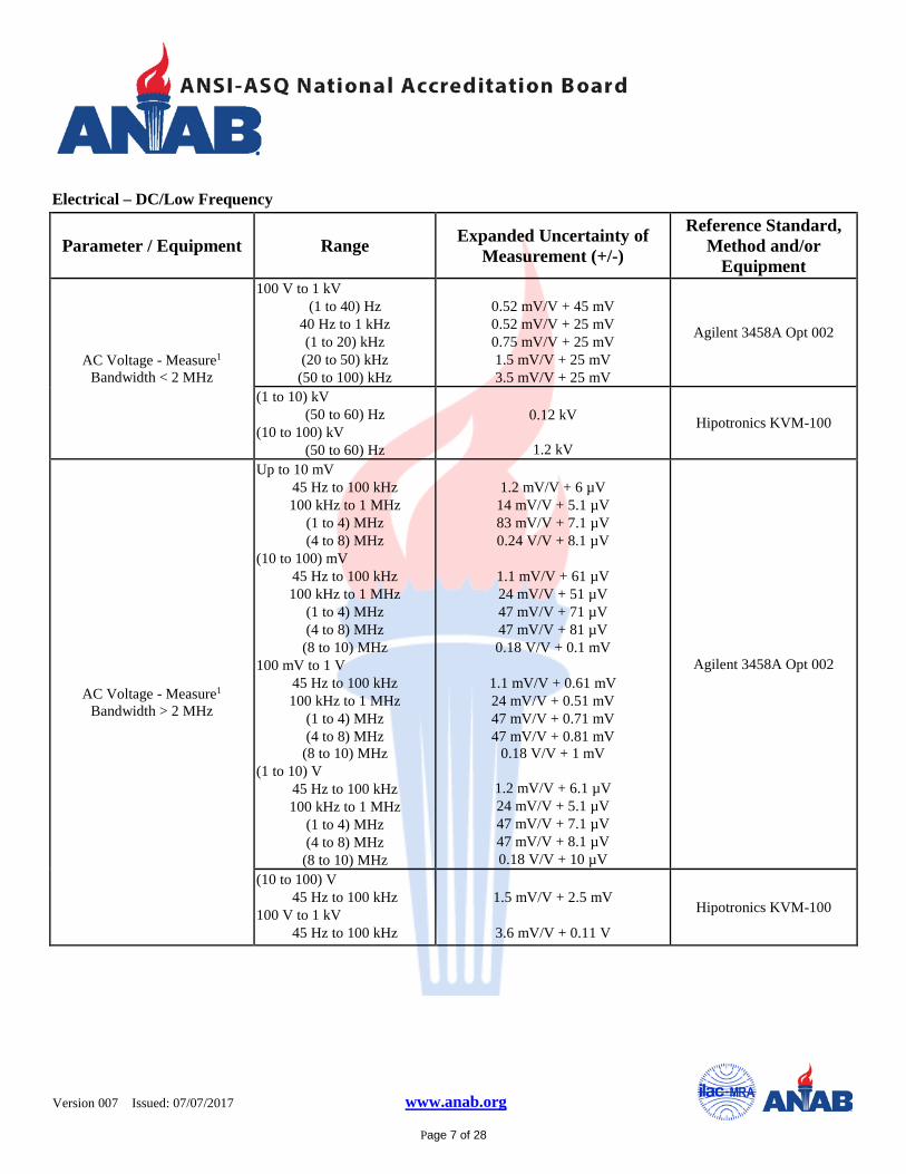
Electrical – DC/Low Frequency
Parameter / Equipment Range Expanded Uncertainty of Measurement (+/-)
Reference Standard, Method and/or
Equipment
AC Voltage - Measure1 Bandwidth < 2 MHz
100 V to 1 kV (1 to 40) Hz
40 Hz to 1 kHz (1 to 20) kHz
(20 to 50) kHz (50 to 100) kHz
0.52 mV/V + 45 mV 0.52 mV/V + 25 mV 0.75 mV/V + 25 mV 1.5 mV/V + 25 mV 3.5 mV/V + 25 mV
Agilent 3458A Opt 002
(1 to 10) kV (50 to 60) Hz
(10 to 100) kV (50 to 60) Hz
0.12 kV
1.2 kV
Hipotronics KVM-100
AC Voltage - Measure1 Bandwidth > 2 MHz
Up to 10 mV 45 Hz to 100 kHz 100 kHz to 1 MHz
(1 to 4) MHz (4 to 8) MHz
(10 to 100) mV 45 Hz to 100 kHz 100 kHz to 1 MHz
(1 to 4) MHz (4 to 8) MHz
(8 to 10) MHz 100 mV to 1 V
45 Hz to 100 kHz 100 kHz to 1 MHz
(1 to 4) MHz (4 to 8) MHz
(8 to 10) MHz (1 to 10) V
45 Hz to 100 kHz 100 kHz to 1 MHz
(1 to 4) MHz (4 to 8) MHz
(8 to 10) MHz
1.2 mV/V + 6 µV
14 mV/V + 5.1 µV 83 mV/V + 7.1 µV 0.24 V/V + 8.1 µV
1.1 mV/V + 61 µV 24 mV/V + 51 µV 47 mV/V + 71 µV 47 mV/V + 81 µV 0.18 V/V + 0.1 mV
1.1 mV/V + 0.61 mV 24 mV/V + 0.51 mV 47 mV/V + 0.71 mV 47 mV/V + 0.81 mV
0.18 V/V + 1 mV
1.2 mV/V + 6.1 µV 24 mV/V + 5.1 µV 47 mV/V + 7.1 µV 47 mV/V + 8.1 µV 0.18 V/V + 10 µV
Agilent 3458A Opt 002
(10 to 100) V 45 Hz to 100 kHz
100 V to 1 kV 45 Hz to 100 kHz
1.5 mV/V + 2.5 mV
3.6 mV/V + 0.11 V
Hipotronics KVM-100
Version 007
Issued: 07/07/2017 www.anab.org
Page 8 of 28
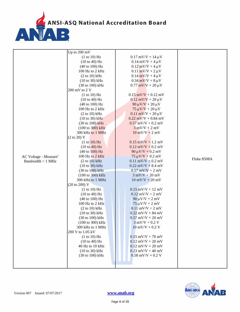
AC Voltage - Measure1 Bandwidth < 1 MHz
Up to 200 mV (1 to 10) Hz
(10 to 40) Hz (40 to 100) Hz
100 Hz to 2 kHz (2 to 10) kHz
(10 to 30) kHz (30 to 100) kHz
200 mV to 2 V (1 to 10) Hz
(10 to 40) Hz (40 to 100) Hz
100 Hz to 2 kHz (2 to 10) kHz
(10 to 30) kHz (30 to 100) kHz
(100 to 300) kHz 300 kHz to 1 MHz
(2 to 20) V (1 to 10) Hz
(10 to 40) Hz (40 to 100) Hz
100 Hz to 2 kHz (2 to 10) kHz
(10 to 30) kHz (30 to 100) kHz
(100 to 300) kHz 300 kHz to 1 MHz
(20 to 200) V (1 to 10) Hz
(10 to 40) Hz (40 to 100) Hz
100 Hz to 2 kHz (2 to 10) kHz
(10 to 30) kHz (30 to 100) kHz
(100 to 300) kHz 300 kHz to 1 MHz
200 V to 1.05 kV (1 to 10) Hz
(10 to 40) Hz 40 Hz to 10 kHz (10 to 30) kHz
(30 to 100) kHz
0.17 mV/V + 14 µV 0.14 mV/V + 4 µV 0.12 mV/V + 4 µV 0.11 mV/V + 2 µV 0.14 mV/V + 4 µV 0.34 mV/V + 8 µV
0.77 mV/V + 20 µV
0.15 mV/V + 0.12 mV 0.12 mV/V + 20 µV 90 µV/V + 20 µV 75 µV/V + 20 µV
0.11 mV/V + 20 µV 0.22 mV/V + 0.84 mV 0.57 mV/V + 0.2 mV
3 mV/V + 2 mV 10 mV/V + 2 mV
0.15 mV/V + 1.2 mV 0.12 mV/V + 0.2 mV 90 µV/V + 0.2 mV 75 µV/V + 0.2 mV
0.11 mV/V + 0.2 mV 0.22 mV/V + 8.4 mV 0.57 mV/V + 2 mV 3 mV/V + 20 mV
10 mV/V + 20 mV
0.15 mV/V + 12 mV 0.12 mV/V + 2 mV 90 µV/V + 2 mV 75 µV/V + 2 mV
0.11 mV/V + 2 mV 0.22 mV/V + 84 mV 0.57 mV/V + 20 mV
3 mV/V + 0.2 V 10 mV/V + 0.2 V
0.15 mV/V + 70 mV 0.12 mV/V + 20 mV 0.12 mV/V + 20 mV 0.23 mV/V + 40 mV 0.58 mV/V + 0.2 V
Fluke 8508A
Version 007
Issued: 07/07/2017 www.anab.org
Page 9 of 28
Electrical – DC/Low Frequency
Parameter / Equipment Range Expanded Uncertainty of Measurement (+/-)
Reference Standard, Method and/or
Equipment
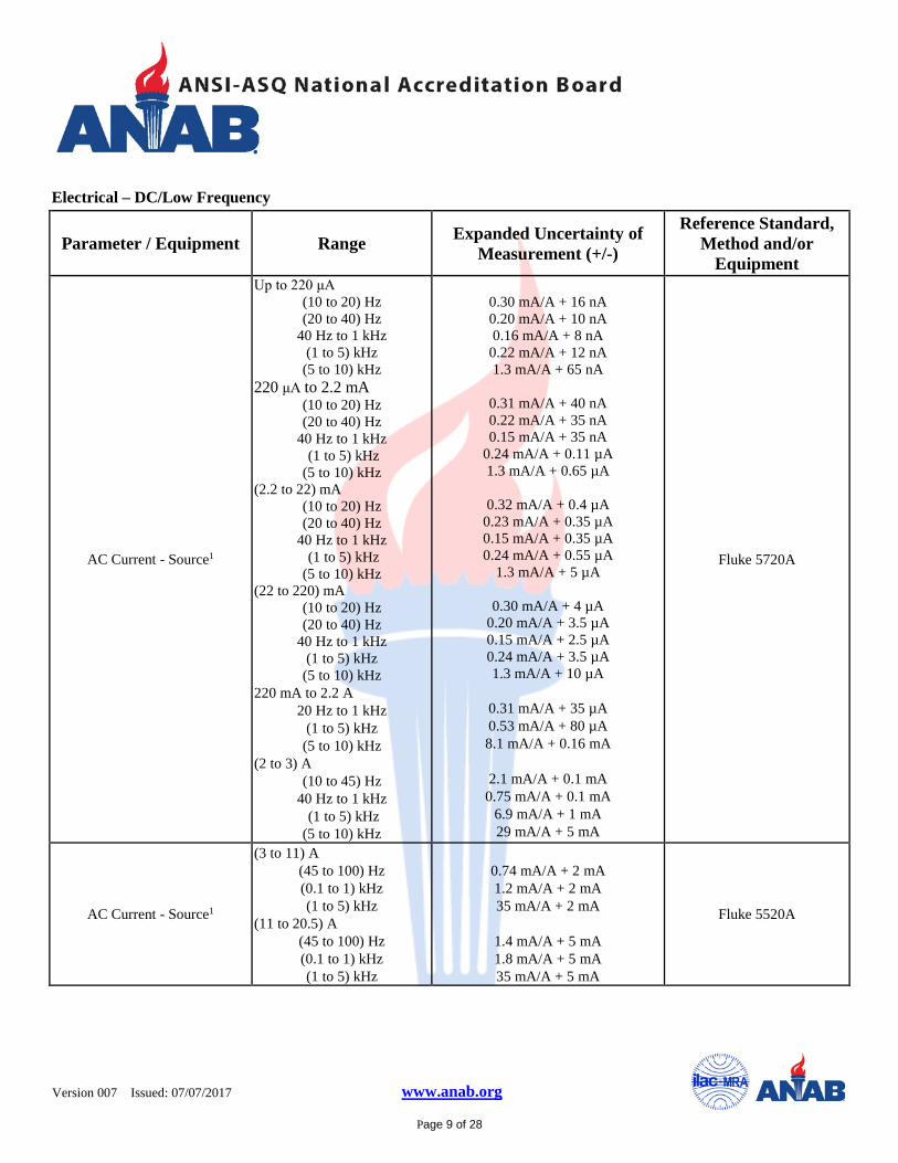
AC Current - Source1
Up to 220 μA (10 to 20) Hz (20 to 40) Hz
40 Hz to 1 kHz (1 to 5) kHz
(5 to 10) kHz 220 μA to 2.2 mA
(10 to 20) Hz (20 to 40) Hz
40 Hz to 1 kHz (1 to 5) kHz (5 to 10) kHz
(2.2 to 22) mA (10 to 20) Hz (20 to 40) Hz
40 Hz to 1 kHz (1 to 5) kHz (5 to 10) kHz
(22 to 220) mA (10 to 20) Hz (20 to 40) Hz
40 Hz to 1 kHz (1 to 5) kHz
(5 to 10) kHz 220 mA to 2.2 A
20 Hz to 1 kHz (1 to 5) kHz
(5 to 10) kHz (2 to 3) A
(10 to 45) Hz 40 Hz to 1 kHz (1 to 5) kHz (5 to 10) kHz
0.30 mA/A + 16 nA 0.20 mA/A + 10 nA 0.16 mA/A + 8 nA
0.22 mA/A + 12 nA 1.3 mA/A + 65 nA
0.31 mA/A + 40 nA 0.22 mA/A + 35 nA 0.15 mA/A + 35 nA
0.24 mA/A + 0.11 µA 1.3 mA/A + 0.65 µA
0.32 mA/A + 0.4 µA
0.23 mA/A + 0.35 µA 0.15 mA/A + 0.35 µA 0.24 mA/A + 0.55 µA
1.3 mA/A + 5 µA
0.30 mA/A + 4 µA 0.20 mA/A + 3.5 µA 0.15 mA/A + 2.5 µA 0.24 mA/A + 3.5 µA 1.3 mA/A + 10 µA
0.31 mA/A + 35 µA 0.53 mA/A + 80 µA 8.1 mA/A + 0.16 mA
2.1 mA/A + 0.1 mA
0.75 mA/A + 0.1 mA 6.9 mA/A + 1 mA 29 mA/A + 5 mA
Fluke 5720A
AC Current - Source1
(3 to 11) A (45 to 100) Hz (0.1 to 1) kHz (1 to 5) kHz
(11 to 20.5) A (45 to 100) Hz (0.1 to 1) kHz (1 to 5) kHz
0.74 mA/A + 2 mA 1.2 mA/A + 2 mA 35 mA/A + 2 mA
1.4 mA/A + 5 mA 1.8 mA/A + 5 mA 35 mA/A + 5 mA
Fluke 5520A
Version 007
Issued: 07/07/2017 www.anab.org
Page 10 of 28
Electrical – DC/Low Frequency
Parameter / Equipment Range Expanded Uncertainty of Measurement (+/-)
Reference Standard, Method and/or
Equipment
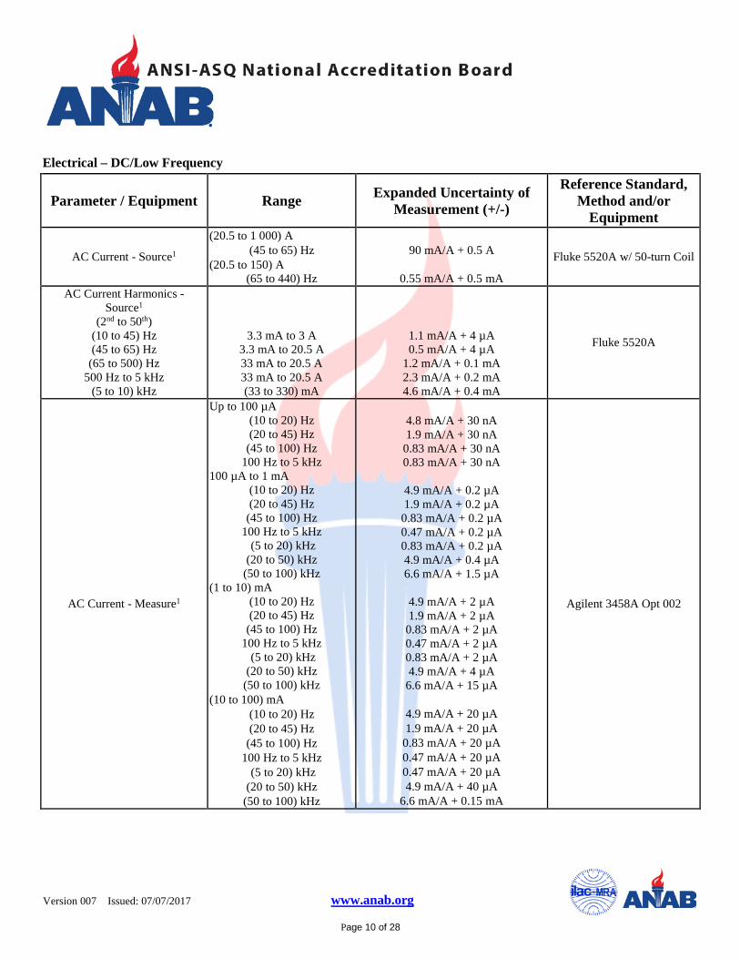
AC Current - Source1
(20.5 to 1 000) A (45 to 65) Hz
(20.5 to 150) A (65 to 440) Hz
90 mA/A + 0.5 A
0.55 mA/A + 0.5 mA
Fluke 5520A w/ 50-turn Coil
AC Current Harmonics - Source1
(2nd to 50th) (10 to 45) Hz (45 to 65) Hz
(65 to 500) Hz 500 Hz to 5 kHz
(5 to 10) kHz
3.3 mA to 3 A 3.3 mA to 20.5 A 33 mA to 20.5 A 33 mA to 20.5 A (33 to 330) mA
1.1 mA/A + 4 µA 0.5 mA/A + 4 µA
1.2 mA/A + 0.1 mA 2.3 mA/A + 0.2 mA 4.6 mA/A + 0.4 mA
Fluke 5520A
AC Current - Measure1
Up to 100 µA (10 to 20) Hz (20 to 45) Hz
(45 to 100) Hz 100 Hz to 5 kHz
100 µA to 1 mA (10 to 20) Hz (20 to 45) Hz
(45 to 100) Hz 100 Hz to 5 kHz (5 to 20) kHz (20 to 50) kHz
(50 to 100) kHz (1 to 10) mA
(10 to 20) Hz (20 to 45) Hz
(45 to 100) Hz 100 Hz to 5 kHz (5 to 20) kHz (20 to 50) kHz
(50 to 100) kHz (10 to 100) mA
(10 to 20) Hz (20 to 45) Hz
(45 to 100) Hz 100 Hz to 5 kHz (5 to 20) kHz (20 to 50) kHz
(50 to 100) kHz
4.8 mA/A + 30 nA 1.9 mA/A + 30 nA
0.83 mA/A + 30 nA 0.83 mA/A + 30 nA
4.9 mA/A + 0.2 µA 1.9 mA/A + 0.2 µA
0.83 mA/A + 0.2 µA 0.47 mA/A + 0.2 µA 0.83 mA/A + 0.2 µA 4.9 mA/A + 0.4 µA 6.6 mA/A + 1.5 µA
4.9 mA/A + 2 µA 1.9 mA/A + 2 µA
0.83 mA/A + 2 µA 0.47 mA/A + 2 µA 0.83 mA/A + 2 µA 4.9 mA/A + 4 µA
6.6 mA/A + 15 µA
4.9 mA/A + 20 µA 1.9 mA/A + 20 µA
0.83 mA/A + 20 µA 0.47 mA/A + 20 µA 0.47 mA/A + 20 µA 4.9 mA/A + 40 µA
6.6 mA/A + 0.15 mA
Agilent 3458A Opt 002
Version 007
Issued: 07/07/2017 www.anab.org
Page 11 of 28
Electrical – DC/Low Frequency
Parameter / Equipment Range Expanded Uncertainty of Measurement (+/-)
Reference Standard, Method and/or
Equipment
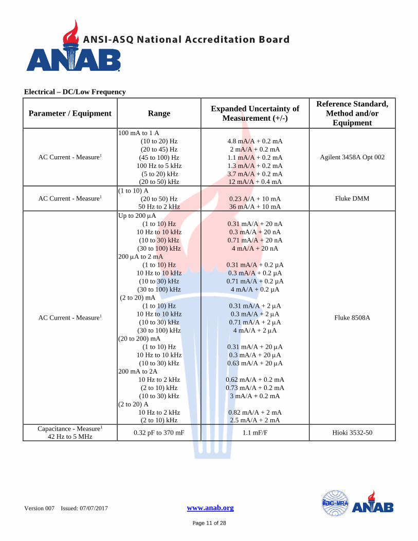
AC Current - Measure1
100 mA to 1 A (10 to 20) Hz (20 to 45) Hz
(45 to 100) Hz 100 Hz to 5 kHz (5 to 20) kHz (20 to 50) kHz
4.8 mA/A + 0.2 mA 2 mA/A + 0.2 mA
1.1 mA/A + 0.2 mA 1.3 mA/A + 0.2 mA 3.7 mA/A + 0.2 mA 12 mA/A + 0.4 mA
Agilent 3458A Opt 002
AC Current - Measure1 (1 to 10) A
(20 to 50) Hz 50 Hz to 2 kHz
0.23 A/A + 10 mA 36 mA/A + 10 mA
Fluke DMM
AC Current - Measure1
Up to 200 µA (1 to 10) Hz
10 Hz to 10 kHz (10 to 30) kHz
(30 to 100) kHz 200 µA to 2 mA
(1 to 10) Hz 10 Hz to 10 kHz (10 to 30) kHz
(30 to 100) kHz (2 to 20) mA
(1 to 10) Hz 10 Hz to 10 kHz (10 to 30) kHz
(30 to 100) kHz (20 to 200) mA
(1 to 10) Hz 10 Hz to 10 kHz (10 to 30) kHz
200 mA to 2A 10 Hz to 2 kHz (2 to 10) kHz
(10 to 30) kHz (2 to 20) A
10 Hz to 2 kHz (2 to 10) kHz
0.31 mA/A + 20 nA 0.3 mA/A + 20 nA
0.71 mA/A + 20 nA 4 mA/A + 20 nA
0.31 mA/A + 0.2 µA 0.3 mA/A + 0.2 µA
0.71 mA/A + 0.2 µA 4 mA/A + 0.2 µA
0.31 mA/A + 2 µA 0.3 mA/A + 2 µA
0.71 mA/A + 2 µA 4 mA/A + 2 µA
0.31 mA/A + 20 µA 0.3 mA/A + 20 µA
0.63 mA/A + 20 µA
0.62 mA/A + 0.2 mA 0.73 mA/A + 0.2 mA
3 mA/A + 0.2 mA
0.82 mA/A + 2 mA 2.5 mA/A + 2 mA
Fluke 8508A
Capacitance - Measure1
42 Hz to 5 MHz 0.32 pF to 370 mF 1.1 mF/F Hioki 3532-50
Version 007
Issued: 07/07/2017 www.anab.org
Page 12 of 28
Electrical – DC/Low Frequency
Parameter / Equipment Range Expanded Uncertainty of Measurement (+/-)
Reference Standard, Method and/or
Equipment
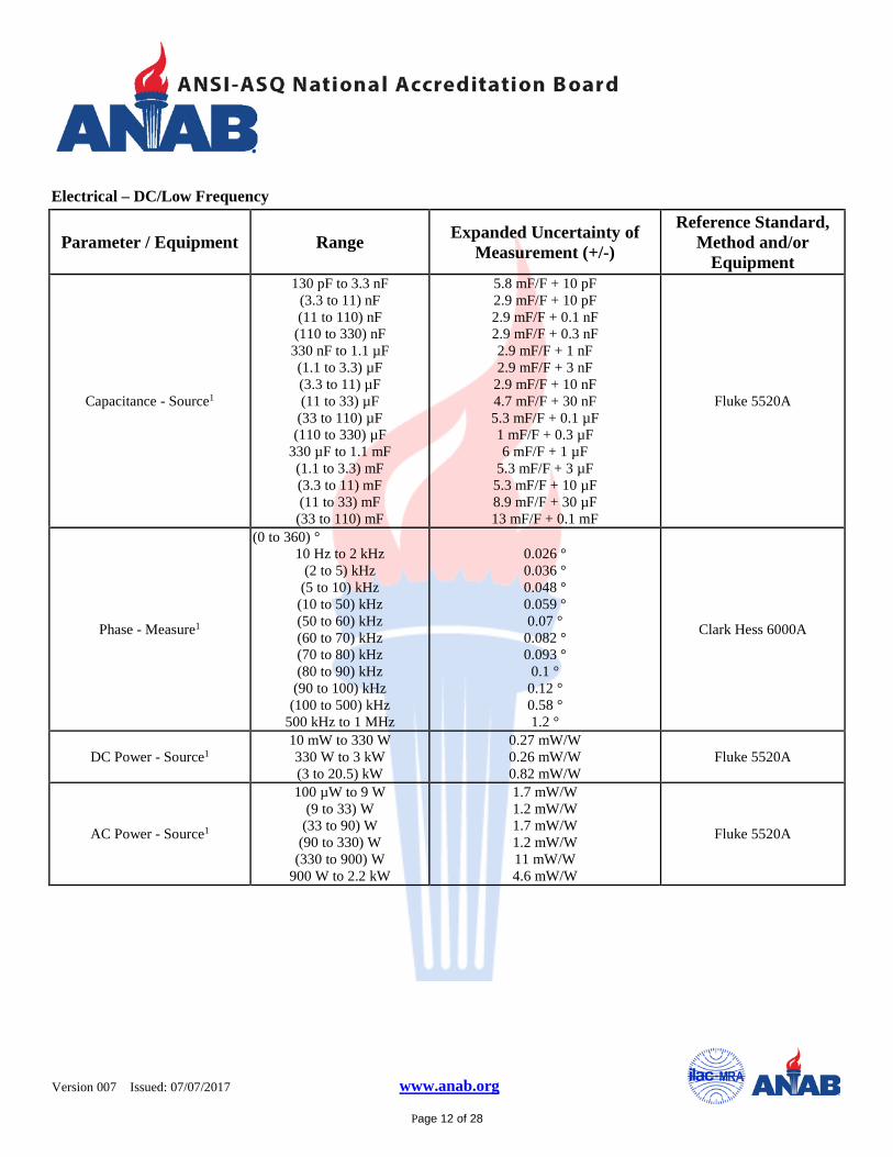
Capacitance - Source1
130 pF to 3.3 nF (3.3 to 11) nF (11 to 110) nF
(110 to 330) nF 330 nF to 1.1 µF (1.1 to 3.3) µF (3.3 to 11) µF (11 to 33) µF
(33 to 110) µF (110 to 330) µF
330 µF to 1.1 mF (1.1 to 3.3) mF (3.3 to 11) mF (11 to 33) mF
(33 to 110) mF
5.8 mF/F + 10 pF 2.9 mF/F + 10 pF 2.9 mF/F + 0.1 nF 2.9 mF/F + 0.3 nF 2.9 mF/F + 1 nF 2.9 mF/F + 3 nF
2.9 mF/F + 10 nF 4.7 mF/F + 30 nF 5.3 mF/F + 0.1 µF 1 mF/F + 0.3 µF 6 mF/F + 1 µF
5.3 mF/F + 3 µF 5.3 mF/F + 10 µF 8.9 mF/F + 30 µF 13 mF/F + 0.1 mF
Fluke 5520A
Phase - Measure1
(0 to 360) ° 10 Hz to 2 kHz
(2 to 5) kHz (5 to 10) kHz
(10 to 50) kHz (50 to 60) kHz (60 to 70) kHz (70 to 80) kHz (80 to 90) kHz
(90 to 100) kHz (100 to 500) kHz
500 kHz to 1 MHz
0.026 ° 0.036 ° 0.048 ° 0.059 ° 0.07 °
0.082 ° 0.093 °
0.1 ° 0.12 ° 0.58 ° 1.2 °
Clark Hess 6000A
DC Power - Source1 10 mW to 330 W 330 W to 3 kW (3 to 20.5) kW
0.27 mW/W 0.26 mW/W 0.82 mW/W
Fluke 5520A
AC Power - Source1
100 µW to 9 W (9 to 33) W
(33 to 90) W (90 to 330) W
(330 to 900) W 900 W to 2.2 kW
1.7 mW/W 1.2 mW/W 1.7 mW/W 1.2 mW/W 11 mW/W 4.6 mW/W
Fluke 5520A
Version 007
Issued: 07/07/2017 www.anab.org
Page 13 of 28
Electrical – DC/Low Frequency
Parameter / Equipment Range Expanded Uncertainty of Measurement (+/-)
Reference Standard, Method and/or
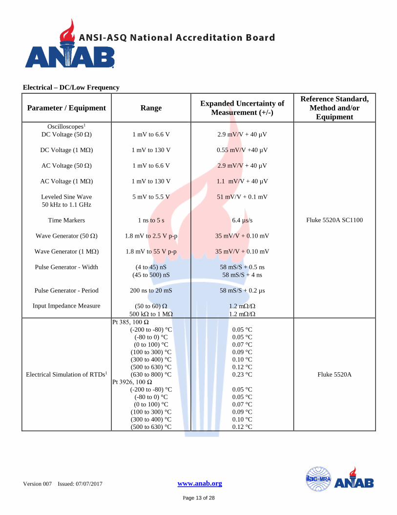
Equipment Oscilloscopes1
DC Voltage (50 Ω)
DC Voltage (1 MΩ)
AC Voltage (50 Ω)
AC Voltage (1 MΩ)
Leveled Sine Wave 50 kHz to 1.1 GHz
Time Markers
Wave Generator (50 Ω)
Wave Generator (1 MΩ)
Pulse Generator - Width
Pulse Generator - Period
Input Impedance Measure
1 mV to 6.6 V
1 mV to 130 V
1 mV to 6.6 V
1 mV to 130 V
5 mV to 5.5 V
1 ns to 5 s
1.8 mV to 2.5 V p-p
1.8 mV to 55 V p-p
(4 to 45) nS (45 to 500) nS
200 ns to 20 mS
(50 to 60) Ω
500 kΩ to 1 MΩ
2.9 mV/V + 40 µV
0.55 mV/V +40 µV
2.9 mV/V + 40 µV
1.1 mV/V + 40 µV
51 mV/V + 0.1 mV
6.4 µs/s
35 mV/V + 0.10 mV
35 mV/V + 0.10 mV
58 mS/S + 0.5 ns 58 mS/S + 4 ns
58 mS/S + 0.2 µs
1.2 mΩ/Ω 1.2 mΩ/Ω
Fluke 5520A SC1100
Electrical Simulation of RTDs1
Pt 385, 100 Ω (-200 to -80) °C
(-80 to 0) °C (0 to 100) °C
(100 to 300) °C (300 to 400) °C (500 to 630) °C (630 to 800) °C
Pt 3926, 100 Ω (-200 to -80) °C
(-80 to 0) °C (0 to 100) °C
(100 to 300) °C (300 to 400) °C (500 to 630) °C
0.05 °C 0.05 °C 0.07 °C 0.09 °C 0.10 °C 0.12 °C 0.23 °C
0.05 °C 0.05 °C 0.07 °C 0.09 °C 0.10 °C 0.12 °C
Fluke 5520A
Version 007
Issued: 07/07/2017 www.anab.org
Page 14 of 28
Electrical – DC/Low Frequency
Parameter / Equipment Range Expanded Uncertainty of Measurement (+/-)
Reference Standard, Method and/or
Equipment
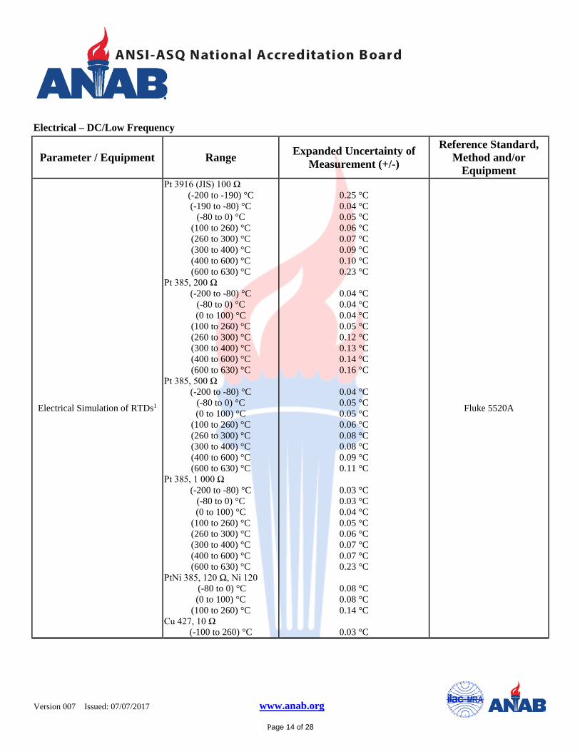
Electrical Simulation of RTDs1
Pt 3916 (JIS) 100 Ω (-200 to -190) °C (-190 to -80) °C
(-80 to 0) °C (100 to 260) °C (260 to 300) °C (300 to 400) °C (400 to 600) °C (600 to 630) °C
Pt 385, 200 Ω (-200 to -80) °C
(-80 to 0) °C (0 to 100) °C
(100 to 260) °C (260 to 300) °C (300 to 400) °C (400 to 600) °C (600 to 630) °C
Pt 385, 500 Ω (-200 to -80) °C
(-80 to 0) °C (0 to 100) °C
(100 to 260) °C (260 to 300) °C (300 to 400) °C (400 to 600) °C (600 to 630) °C
Pt 385, 1 000 Ω (-200 to -80) °C
(-80 to 0) °C (0 to 100) °C
(100 to 260) °C (260 to 300) °C (300 to 400) °C (400 to 600) °C (600 to 630) °C
PtNi 385, 120 Ω, Ni 120 (-80 to 0) °C (0 to 100) °C
(100 to 260) °C Cu 427, 10 Ω
(-100 to 260) °C
0.25 °C 0.04 °C 0.05 °C 0.06 °C 0.07 °C 0.09 °C 0.10 °C 0.23 °C
0.04 °C 0.04 °C 0.04 °C 0.05 °C 0.12 °C 0.13 °C 0.14 °C 0.16 °C
0.04 °C 0.05 °C 0.05 °C 0.06 °C 0.08 °C 0.08 °C 0.09 °C 0.11 °C
0.03 °C 0.03 °C 0.04 °C 0.05 °C 0.06 °C 0.07 °C 0.07 °C 0.23 °C
0.08 °C 0.08 °C 0.14 °C
0.03 °C
Fluke 5520A

Version 007
Issued: 07/07/2017 www.anab.org
Page 15 of 28
Electrical – DC/Low Frequency
Parameter / Equipment Range Expanded Uncertainty of Measurement (+/-)
Reference Standard, Method and/or
Equipment
Electrical Simulation of Thermocouples1
Type K (-200 to -100) °C (-100 to -25) °C (-25 to 120) °C
(120 to 1 000) °C (1 000 to 1 372) °C
Type J (-210 to -100) °C (-100 to -30) °C (-30 to 150) °C (150 to 760) °C
(760 to 1 200) °C Type E
(-250 to -100) °C (-100 to -35) °C (-25 to 350) °C (350 to 650) °C
(650 to 1 000) °C Type T
(-250 to -150) °C (-150 to 0) °C (0 to 120) °C
(120 to 400) °C Type S
(0 to 250) °C (250 to 1 000) °C
(1 000 to 1400) °C (1 400 to 1 767) °C
Type B (600 to 800) °C (-100 to -25) °C (-25 to 120) °C
(120 to 1 000) °C Type C
(0 to 150) °C (150 to 650) °C
(650 to 1 000) °C (1 000 to 1 800) °C (1 800 to 2 316) °C
Type L (-200 to -100) °C (-100 to 800) °C (800 to 900) °C
0.33 °C 0.18 °C 0.16 °C 0.26 °C 0.40 °C
0.27 °C 0.16 °C 0.14°C 0.17°C 0.23°C
0.50 °C 0.16 °C 0.14°C 0.16°C 0.21°C
0.63 °C 0.24 °C 0.16 °C 0.14 °C
0.47 °C 0.36 °C 0.37 °C 0.46 °C
0.44 °C 0.34 °C 0.30 °C 0.33 °C
0.30 °C 0.26 °C 0.31 °C 0.50 °C 0.84 °C
0.37 °C 0.26 °C 0.17 °C
Fluke 5520A
Version 007
Issued: 07/07/2017 www.anab.org
Page 16 of 28
Electrical – DC/Low Frequency
Parameter / Equipment Range Expanded Uncertainty of Measurement (+/-)
Reference Standard, Method and/or
Equipment
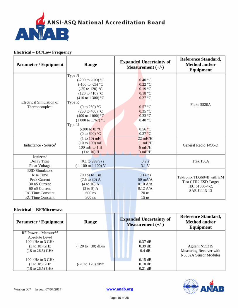
Electrical Simulation of Thermocouples1
Type N (-200 to -100) °C (-100 to -25) °C (-25 to 120) °C (120 to 410) °C
(410 to 1 300) °C Type R
(0 to 250) °C (250 to 400) °C
(400 to 1 000) °C (1 000 to 1767) °C
Type U (-200 to 0) °C (0 to 600) °C
0.40 °C 0.22 °C 0.19 °C 0.18 °C 0.27 °C
0.57 °C 0.35 °C 0.33 °C 0.40 °C
0.56 °C 0.27 °C
Fluke 5520A
Inductance - Source1
(1 to 10) mH (10 to 100) mH 100 mH to 1 H
(1 to 10) H
22 mH/H 11 mH/H 6 mH/H 3 mH/H
General Radio 1490-D
Ionizers1
Decay Time Float Voltage
(0.1 to 999.9) s
(-1 100 to 1 100) V
0.2 s 3.1 V
Trek 156A
ESD Simulators
Rise Time Peak Current 30 nS Current 60 nS Current
RC Time Constant RC Time Constant
700 ps to 1 ns (7.5 to 30) A (4 to 16) A (2 to 8) A
600 ns 300 ns
0.14 ns
50 mA/A 0.10 A/A 0.12 A/A
20 ns 15 ns
Tektronix TDS684B with EM Test CTR2 ESD Target
IEC 61000-4-2, SAE J1113-13
Electrical - RF/Microwave
Parameter / Equipment Range Expanded Uncertainty of Measurement (+/-)
Reference Standard, Method and/or
Equipment RF Power – Measure1,4
Absolute Level 100 kHz to 3 GHz
(3 to 18) GHz (18 to 26.5) GHz
100 kHz to 3 GHz
(3 to 18) GHz (18 to 26.5) GHz
(+20 to +30) dBm
(-20 to +20) dBm
0.37 dB 0.39 dB 0.4 dB
0.15 dB 0.18 dB 0.21 dB
Agilent N5531S Measuring Receiver with N5532A Sensor Modules

Version 007
Issued: 07/07/2017 www.anab.org
Page 17 of 28
Electrical - RF/Microwave
Parameter / Equipment Range Expanded Uncertainty of Measurement (+/-)
Reference Standard, Method and/or
Equipment Relative Level
(3.05 to 6.6) GHz
(6.6 to 13.2) GHz
(13.2 to 19.2) GHz
(19.2 to 26.5) GHz
(-90 to +30) dBm (-113 to -90) dBm
(-81 to +30) dBm (-104 to -81) dBm
(-70 to +30) dBm (-93 to -70) dBm
(-62 to +30) dBm (-85 to -62) dBm
0.026 dB + 0.005 dB/10 dB 0.067 dB + 0.12 dB/10 dB
0.026 dB + 0.005 dB/10 dB 0.062 dB + 0.12 dB/10 dB
0.026 dB + 0.005 dB/10 dB 0.056 dB + 0.12 dB/10 dB
0.026 dB + 0.005 dB/10 dB 0.051 dB + 0.12 dB/10 dB
Agilent N5531S Measuring Receiver with N5532A Sensor Modules
Amplitude Modulation - Source1,4
Rate: DC to 100 kHz Depths: 0 % to 100 %
250 kHz to 40 GHz 7.1 % of setting + 1 % Agilent E8257D
Amplitude Modulation - Measure1,4
100 kHz to 10 MHz
10 MHz to 3 GHz
10 MHz to 3 GHz
(3 to 26.5) GHz
(3 to 26.5) GHz
Rate: 50 Hz to 10 kHz Depths: 5 % to 99 %
Rate: 50 Hz to 100 kHz Depths: 20 % to 99 %
Rate: 50 Hz to 100 kHz
Depths: 5 % to 20 %
Rate: 50 Hz to 100 kHz Depths: 20 % to 99 %
Rate: 50 Hz to 100 kHz
Depths: 5 % to 20 %
2.2 % of reading
1.2 % of reading
4.2 % of reading
3.5 % of reading
6 % of reading
Agilent N5531S Measuring Receiver with N5532A Sensor Modules
Phase Modulation - Source1,4
Rate: DC to 100 kHz 250 kHz to 40 GHz 5.9 % setting + 0.1 rad Agilent E8257D
Version 007
Issued: 07/07/2017 www.anab.org
Page 18 of 28
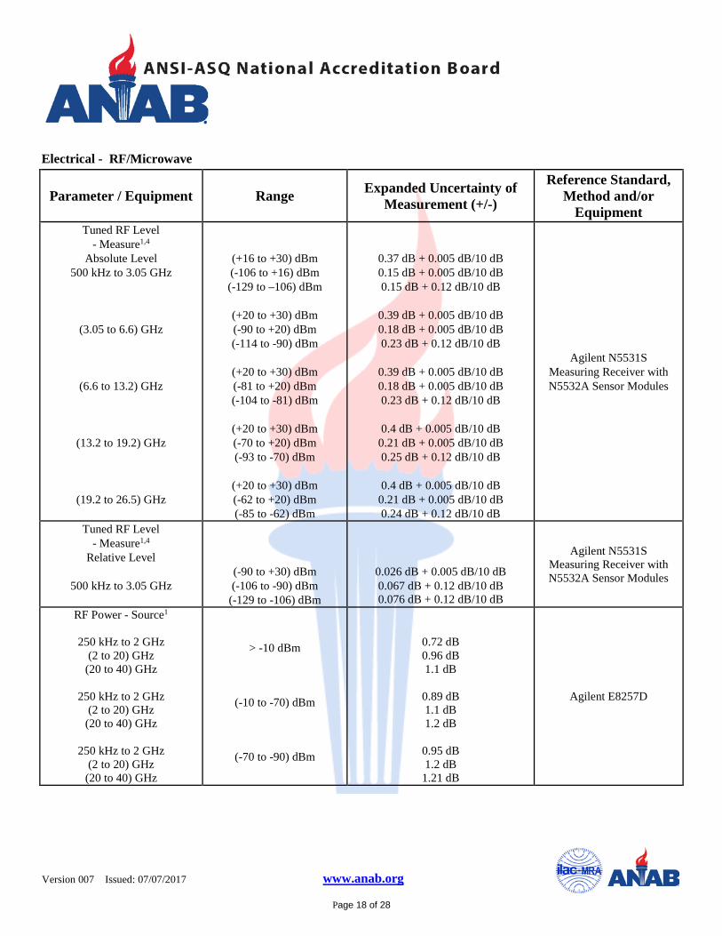
Electrical - RF/Microwave
Parameter / Equipment Range Expanded Uncertainty of Measurement (+/-)
Reference Standard, Method and/or
Equipment Tuned RF Level
- Measure1,4 Absolute Level
500 kHz to 3.05 GHz
(3.05 to 6.6) GHz
(6.6 to 13.2) GHz
(13.2 to 19.2) GHz
(19.2 to 26.5) GHz
(+16 to +30) dBm (-106 to +16) dBm (-129 to –106) dBm
(+20 to +30) dBm (-90 to +20) dBm (-114 to -90) dBm
(+20 to +30) dBm (-81 to +20) dBm (-104 to -81) dBm
(+20 to +30) dBm (-70 to +20) dBm (-93 to -70) dBm
(+20 to +30) dBm (-62 to +20) dBm (-85 to -62) dBm
0.37 dB + 0.005 dB/10 dB 0.15 dB + 0.005 dB/10 dB 0.15 dB + 0.12 dB/10 dB
0.39 dB + 0.005 dB/10 dB 0.18 dB + 0.005 dB/10 dB 0.23 dB + 0.12 dB/10 dB
0.39 dB + 0.005 dB/10 dB 0.18 dB + 0.005 dB/10 dB 0.23 dB + 0.12 dB/10 dB
0.4 dB + 0.005 dB/10 dB
0.21 dB + 0.005 dB/10 dB 0.25 dB + 0.12 dB/10 dB
0.4 dB + 0.005 dB/10 dB
0.21 dB + 0.005 dB/10 dB 0.24 dB + 0.12 dB/10 dB
Agilent N5531S Measuring Receiver with N5532A Sensor Modules
Tuned RF Level - Measure1,4
Relative Level
500 kHz to 3.05 GHz
(-90 to +30) dBm (-106 to -90) dBm
(-129 to -106) dBm
0.026 dB + 0.005 dB/10 dB 0.067 dB + 0.12 dB/10 dB 0.076 dB + 0.12 dB/10 dB
Agilent N5531S Measuring Receiver with N5532A Sensor Modules
RF Power - Source1
250 kHz to 2 GHz (2 to 20) GHz
(20 to 40) GHz
250 kHz to 2 GHz (2 to 20) GHz
(20 to 40) GHz
250 kHz to 2 GHz (2 to 20) GHz
(20 to 40) GHz
> -10 dBm
(-10 to -70) dBm
(-70 to -90) dBm
0.72 dB 0.96 dB 1.1 dB
0.89 dB 1.1 dB 1.2 dB
0.95 dB 1.2 dB
1.21 dB
Agilent E8257D
Version 007
Issued: 07/07/2017 www.anab.org
Page 19 of 28
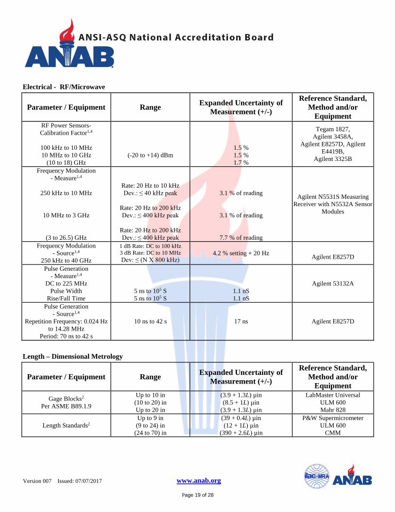
Electrical - RF/Microwave
Parameter / Equipment Range Expanded Uncertainty of Measurement (+/-)
Reference Standard, Method and/or
Equipment RF Power Sensors- Calibration Factor1,4
100 kHz to 10 MHz 10 MHz to 10 GHz
(10 to 18) GHz
(-20 to +14) dBm
1.5 % 1.5 % 1.7 %
Tegam 1827, Agilent 3458A,
Agilent E8257D, Agilent E4419B,
Agilent 3325B
Frequency Modulation - Measure1,4
250 kHz to 10 MHz
10 MHz to 3 GHz
(3 to 26.5) GHz
Rate: 20 Hz to 10 kHz Dev.: ≤ 40 kHz peak
Rate: 20 Hz to 200 kHz Dev.: ≤ 400 kHz peak
Rate: 20 Hz to 200 kHz Dev.: ≤ 400 kHz peak
3.1 % of reading
3.1 % of reading
7.7 % of reading
Agilent N5531S Measuring Receiver with N5532A Sensor
Modules
Frequency Modulation - Source1,4
250 kHz to 40 GHz
1 dB Rate: DC to 100 kHz 3 dB Rate: DC to 10 MHz Dev: ≤ (N X 800 kHz)
4.2 % setting + 20 Hz Agilent E8257D
Pulse Generation - Measure1,4
DC to 225 MHz Pulse Width
Rise/Fall Time
5 ns to 105 S 5 ns to 105 S
1.1 nS 1.1 nS
Agilent 53132A
Pulse Generation - Source1,4
Repetition Frequency: 0.024 Hz to 14.28 MHz
Period: 70 ns to 42 s
10 ns to 42 s 17 ns Agilent E8257D
Length – Dimensional Metrology
Parameter / Equipment Range Expanded Uncertainty of Measurement (+/-)
Reference Standard, Method and/or
Equipment Gage Blocks2
Per ASME B89.1.9 Up to 10 in (10 to 20) in Up to 20 in
(3.9 + 1.3L) µin (8.5 + 1L) µin
(3.9 + 1.3L) µin
LabMaster Universal ULM 600 Mahr 828
Length Standards2 Up to 9 in (9 to 24) in
(24 to 70) in
(39 + 0.4L) µin (12 + 1L) µin
(390 + 2.6L) µin
P&W Supermicrometer ULM 600
CMM
Version 007
Issued: 07/07/2017 www.anab.org
Page 20 of 28
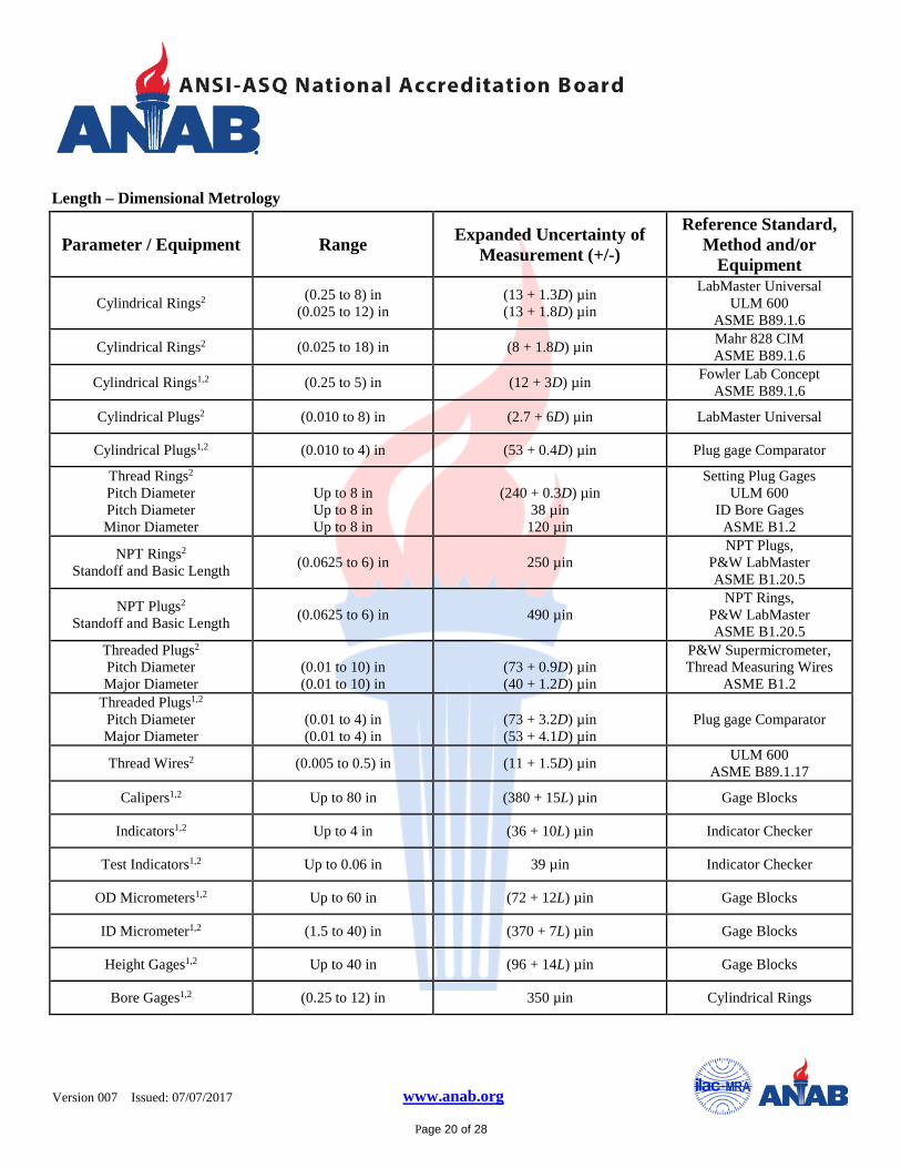
Length – Dimensional Metrology
Parameter / Equipment Range Expanded Uncertainty of Measurement (+/-)
Reference Standard, Method and/or
Equipment
Cylindrical Rings2 (0.25 to 8) in (0.025 to 12) in
(13 + 1.3D) µin (13 + 1.8D) µin
LabMaster Universal ULM 600
ASME B89.1.6
Cylindrical Rings2 (0.025 to 18) in (8 + 1.8D) µin Mahr 828 CIM ASME B89.1.6
Cylindrical Rings1,2 (0.25 to 5) in (12 + 3D) µin Fowler Lab Concept ASME B89.1.6
Cylindrical Plugs2 (0.010 to 8) in (2.7 + 6D) µin LabMaster Universal
Cylindrical Plugs1,2 (0.010 to 4) in (53 + 0.4D) µin Plug gage Comparator
Thread Rings2
Pitch Diameter Pitch Diameter Minor Diameter
Up to 8 in Up to 8 in Up to 8 in
(240 + 0.3D) µin
38 µin 120 µin
Setting Plug Gages ULM 600
ID Bore Gages ASME B1.2
NPT Rings2
Standoff and Basic Length (0.0625 to 6) in 250 µin NPT Plugs,
P&W LabMaster ASME B1.20.5
NPT Plugs2
Standoff and Basic Length (0.0625 to 6) in 490 µin NPT Rings,
P&W LabMaster ASME B1.20.5
Threaded Plugs2 Pitch Diameter Major Diameter
(0.01 to 10) in (0.01 to 10) in
(73 + 0.9D) µin (40 + 1.2D) µin
P&W Supermicrometer, Thread Measuring Wires
ASME B1.2 Threaded Plugs1,2
Pitch Diameter Major Diameter
(0.01 to 4) in (0.01 to 4) in
(73 + 3.2D) µin (53 + 4.1D) µin
Plug gage Comparator
Thread Wires2 (0.005 to 0.5) in (11 + 1.5D) µin ULM 600 ASME B89.1.17
Calipers1,2 Up to 80 in (380 + 15L) µin Gage Blocks
Indicators1,2 Up to 4 in (36 + 10L) µin Indicator Checker
Test Indicators1,2 Up to 0.06 in 39 µin Indicator Checker
OD Micrometers1,2 Up to 60 in (72 + 12L) µin Gage Blocks
ID Micrometer1,2 (1.5 to 40) in (370 + 7L) µin Gage Blocks
Height Gages1,2 Up to 40 in (96 + 14L) µin Gage Blocks
Bore Gages1,2 (0.25 to 12) in 350 µin Cylindrical Rings
Version 007
Issued: 07/07/2017 www.anab.org
Page 21 of 28
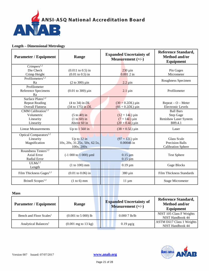
Length – Dimensional Metrology
Parameter / Equipment Range Expanded Uncertainty of Measurement (+/-)
Reference Standard, Method and/or
Equipment Crimpers1,2 Die Check
Crimp Height
(0.011 to 0.5) in (0.01 to 0.5) in
230 µin
0.001 2 in
Pin Gages
Micrometer Profilometers1,2
Ra
(2 to 300) µin
2.2 µin Roughness Specimen
Profilometer Reference Specimens
Ra (0.01 to 300) µin 2.1 µin Profilometer
Surface Plates1,2 Repeat Reading Overall Flatness
(4 to 34) in DL
(34 to 175) in DL
(30 + 0.2DL) µin (66 + 0.2DL) µin
Repeat – O – Meter Electronic Levels
CMM Calibration1,2 Volumetric
Linearity Linearity
(5 to 40) in (1 to 60) in Above 60 in
(12 + 14L) µin (7 + 14L) µin
(20 + 0.4L) µin
Ball Bars Step Gage
Renishaw Laser System B89.4.1
Linear Measurements Up to 1 560 in (38 + 0.5L) µin Laser
Optical Comparators1,2 Linearity
Magnification
Up to 12 in
10x, 20x, 31.25x, 50x, 62.5x, 100x, 200x
(97 + 12L) µin
0.00046 in
Glass Scale
Precision Balls Calibration Sphere
Roundness Testers1,2 Axial Error Radial Error
(-1 000 to 1 000) µml
0.15 µm 0.15 µm
Test Sphere
ULMs1,2 Length (1 to 100) mm 0.19 µm Gage Blocks
Film Thickness Gages1,2 (0.01 to 0.06) in 380 µin Film Thickness Standards
Brinell Scopes1,2 (1 to 6) mm 11 µm Stage Micrometer
Mass
Parameter / Equipment Range Expanded Uncertainty of Measurement (+/-)
Reference Standard, Method and/or
Equipment Bench and Floor Scales1 (0.001 to 5 000) lb 0.000 7 lb/lb NIST 105 Class F Weights
NIST Handbook 44
Analytical Balances1 (0.001 mg to 13 kg) 0.19 µg/g ASTM E617 Class 1 Weights NIST Handbook 44
Version 007
Issued: 07/07/2017 www.anab.org
Page 22 of 28
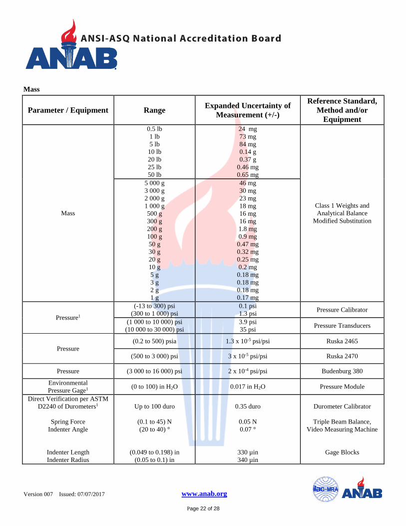
Mass
Parameter / Equipment Range Expanded Uncertainty of Measurement (+/-)
Reference Standard, Method and/or
Equipment
Mass
0.5 lb 1 lb 5 lb
10 lb 20 lb 25 lb 50 lb
24 mg 73 mg 84 mg 0.14 g 0.37 g
0.46 mg 0.65 mg
Class 1 Weights and Analytical Balance
Modified Substitution
5 000 g 3 000 g 2 000 g 1 000 g 500 g 300 g 200 g 100 g 50 g 30 g 20 g 10 g 5 g 3 g 2 g 1 g
46 mg 30 mg 23 mg 18 mg 16 mg 16 mg 1.8 mg 0.9 mg 0.47 mg 0.32 mg 0.25 mg 0.2 mg 0.18 mg 0.18 mg 0.18 mg 0.17 mg
Pressure1
(-13 to 300) psi (300 to 1 000) psi
0.1 psi 1.3 psi Pressure Calibrator
(1 000 to 10 000) psi
(10 000 to 30 000) psi 3.9 psi 35 psi Pressure Transducers
Pressure (0.2 to 500) psia 1.3 x 10⁻⁵ psi/psi Ruska 2465
(500 to 3 000) psi 3 x 10⁻⁵ psi/psi Ruska 2470
Pressure (3 000 to 16 000) psi 2 x 10⁻⁴ psi/psi Budenburg 380
Environmental Pressure Gage1 (0 to 100) in H2O 0.017 in H2O Pressure Module
Direct Verification per ASTM D2240 of Durometers1
Spring Force
Indenter Angle
Indenter Length Indenter Radius
Up to 100 duro
(0.1 to 45) N (20 to 40) °
(0.049 to 0.198) in (0.05 to 0.1) in
0.35 duro
0.05 N 0.07 °
330 µin 340 µin
Durometer Calibrator
Triple Beam Balance,
Video Measuring Machine
Gage Blocks
Version 007
Issued: 07/07/2017 www.anab.org
Page 23 of 28
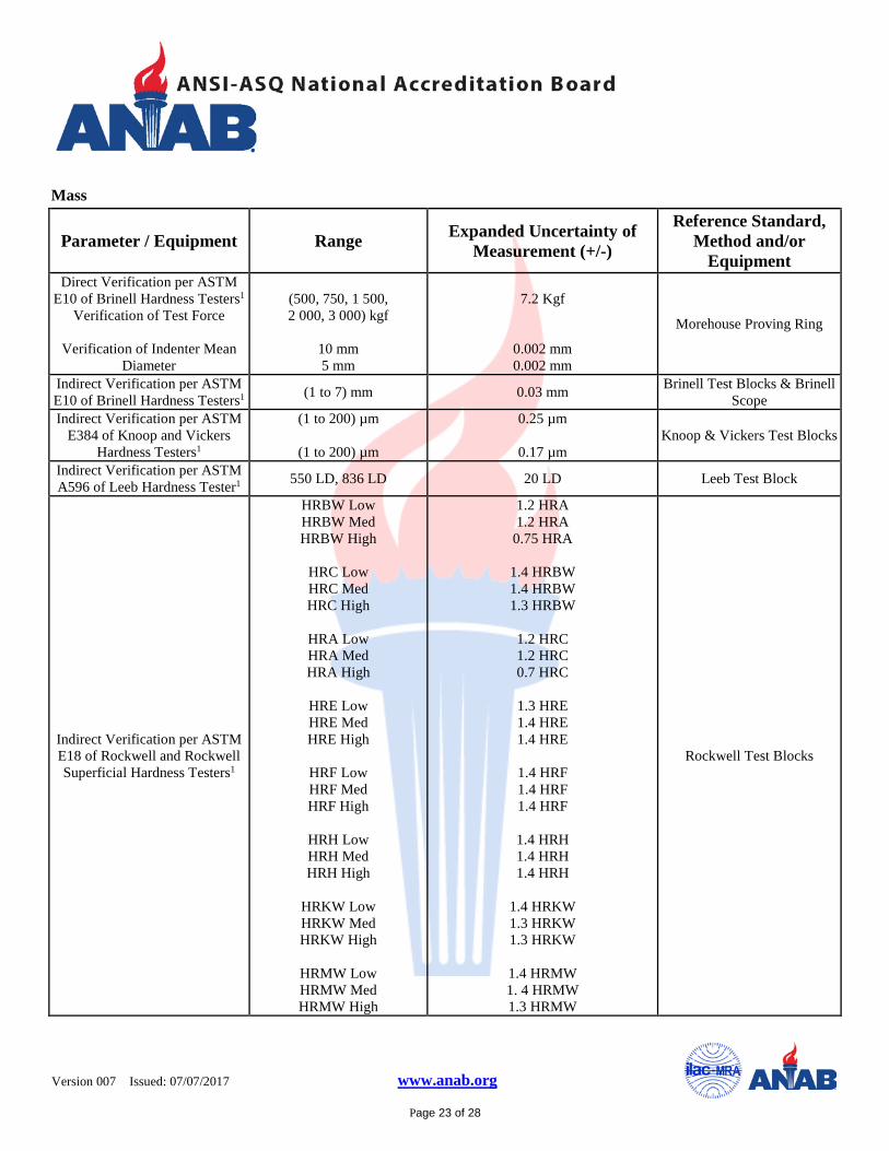
Mass
Parameter / Equipment Range Expanded Uncertainty of Measurement (+/-)
Reference Standard, Method and/or
Equipment Direct Verification per ASTM
E10 of Brinell Hardness Testers1 Verification of Test Force
Verification of Indenter Mean
Diameter
(500, 750, 1 500, 2 000, 3 000) kgf
10 mm 5 mm
7.2 Kgf
0.002 mm 0.002 mm
Morehouse Proving Ring
Indirect Verification per ASTM E10 of Brinell Hardness Testers1 (1 to 7) mm 0.03 mm Brinell Test Blocks & Brinell
Scope Indirect Verification per ASTM
E384 of Knoop and Vickers Hardness Testers1
(1 to 200) µm
(1 to 200) µm
0.25 µm
0.17 µm Knoop & Vickers Test Blocks
Indirect Verification per ASTM A596 of Leeb Hardness Tester1 550 LD, 836 LD 20 LD Leeb Test Block
Indirect Verification per ASTM E18 of Rockwell and Rockwell Superficial Hardness Testers1
HRBW Low HRBW Med HRBW High
HRC Low HRC Med HRC High
HRA Low HRA Med HRA High
HRE Low HRE Med HRE High
HRF Low HRF Med HRF High
HRH Low HRH Med HRH High
HRKW Low HRKW Med HRKW High
HRMW Low HRMW Med HRMW High
1.2 HRA 1.2 HRA
0.75 HRA
1.4 HRBW 1.4 HRBW 1.3 HRBW
1.2 HRC 1.2 HRC 0.7 HRC
1.3 HRE 1.4 HRE 1.4 HRE
1.4 HRF 1.4 HRF 1.4 HRF
1.4 HRH 1.4 HRH 1.4 HRH
1.4 HRKW 1.3 HRKW 1.3 HRKW
1.4 HRMW 1. 4 HRMW 1.3 HRMW
Rockwell Test Blocks
Version 007
Issued: 07/07/2017 www.anab.org
Page 24 of 28
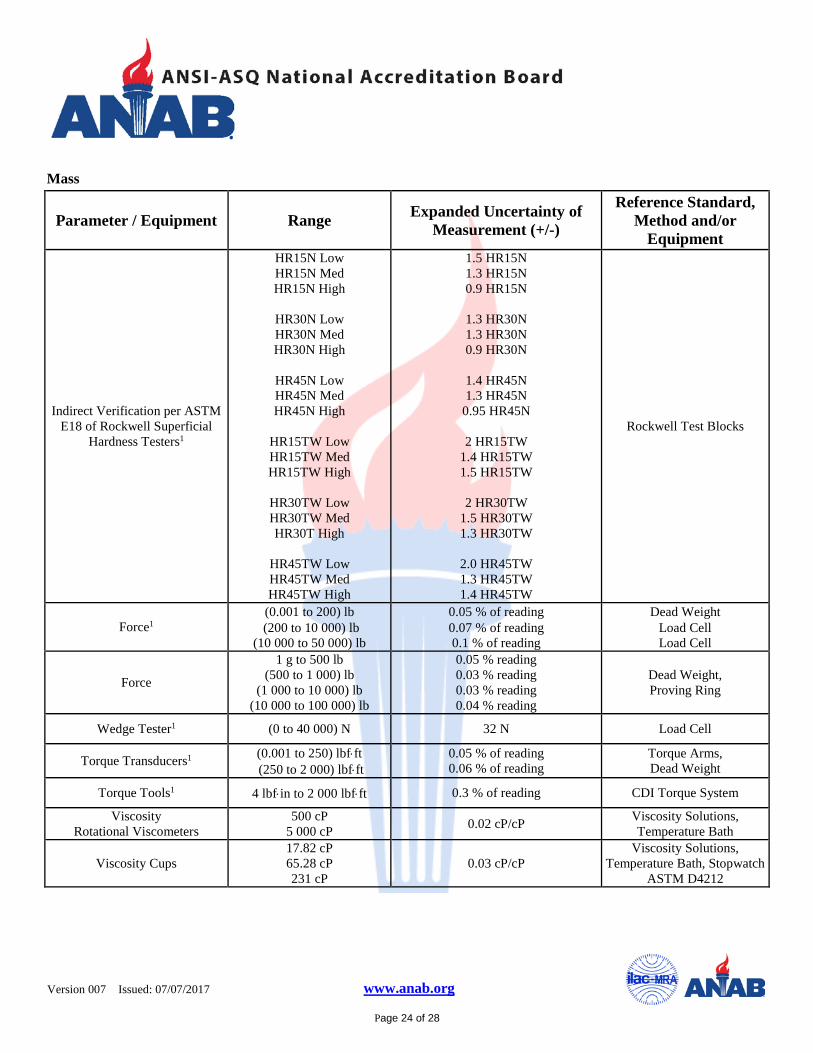
Mass
Parameter / Equipment Range Expanded Uncertainty of Measurement (+/-)
Reference Standard, Method and/or
Equipment
Indirect Verification per ASTM E18 of Rockwell Superficial
Hardness Testers1
HR15N Low HR15N Med HR15N High
HR30N Low HR30N Med HR30N High
HR45N Low HR45N Med HR45N High
HR15TW Low HR15TW Med HR15TW High
HR30TW Low HR30TW Med HR30T High
HR45TW Low HR45TW Med HR45TW High
1.5 HR15N 1.3 HR15N 0.9 HR15N
1.3 HR30N 1.3 HR30N 0.9 HR30N
1.4 HR45N 1.3 HR45N
0.95 HR45N
2 HR15TW 1.4 HR15TW 1.5 HR15TW
2 HR30TW
1.5 HR30TW 1.3 HR30TW
2.0 HR45TW 1.3 HR45TW 1.4 HR45TW
Rockwell Test Blocks
Force1 (0.001 to 200) lb
(200 to 10 000) lb (10 000 to 50 000) lb
0.05 % of reading 0.07 % of reading 0.1 % of reading
Dead Weight Load Cell Load Cell
Force
1 g to 500 lb (500 to 1 000) lb
(1 000 to 10 000) lb (10 000 to 100 000) lb
0.05 % reading 0.03 % reading 0.03 % reading 0.04 % reading
Dead Weight, Proving Ring
Wedge Tester1 (0 to 40 000) N 32 N Load Cell
Torque Transducers1 (0.001 to 250) lbf⋅ft (250 to 2 000) lbf⋅ft
0.05 % of reading 0.06 % of reading
Torque Arms, Dead Weight
Torque Tools1 4 lbf⋅in to 2 000 lbf⋅ft 0.3 % of reading CDI Torque System
Viscosity Rotational Viscometers
500 cP 5 000 cP 0.02 cP/cP Viscosity Solutions,
Temperature Bath
Viscosity Cups 17.82 cP 65.28 cP 231 cP
0.03 cP/cP Viscosity Solutions,
Temperature Bath, Stopwatch ASTM D4212

Version 007
Issued: 07/07/2017 www.anab.org
Page 25 of 28
Mass
Parameter / Equipment Range Expanded Uncertainty of Measurement (+/-)
Reference Standard, Method and/or
Equipment
Pipettes
(100 to 200) µL (200 to 1 000) µL
(1 000 to 5 000) µL (5 000 to 10 000) µL
0.6 µL 0.7 µL 1.9 µL 3.6 µL
Analytical Balance ISO 8655-6
Graduated Cylinder (1 to 200) mL
(200 to 6 000) mL (6 000 to 34 000) mL
0.003 mL 0.46 mL 2.8 mL
Balances
Foundry Sand Test Equipment / Measurement1
AFS Clay Tester
Friability Tester
Sand Rammer
Moisture Teller
Permmeter
Sand Strength Tester
Core Scratch Tester
Green Sand Hardness Tester (B&C)
(0 to 10) min
60 s
(0 to 2) in
(0 to 300 ºF)
(0 to 500) perm
(0 to 500) psi (0 to 1 000) lb
(0 to 0.1) in
(0 to 0.1) in
1.2 s
1.2 s
0.01 in
1.9 ºF
0.43 perm
1.1 psi 4.2 lb
0.006 in
0.006 in
Stopwatch
Stopwatch
Impact Rings
Temperature Calibrator
Perm Standards
Proving Ring
Flatness Block
Flatness Block Foundry Sand Test Equipment /
Measurement 1 Ultrasonic Cleaner/Scrubber
Wet Tensile Tester
Sand Squeezer
Tensile Testers
18 ºF 30 min
0.449 N/cm²
(300 to 320) ºF
(0 to 200) psi
(0 to 10 000) lb
1.7 ºF 1.2 sec
0.003 1 N/cm²
2 ºF
3.8 psi
7.2 lb
Temperature Calibrator Stopwatch
Dead Weight
Temperature Calibrator
Proving Ring
Load Cell
Version 007
Issued: 07/07/2017 www.anab.org
Page 26 of 28
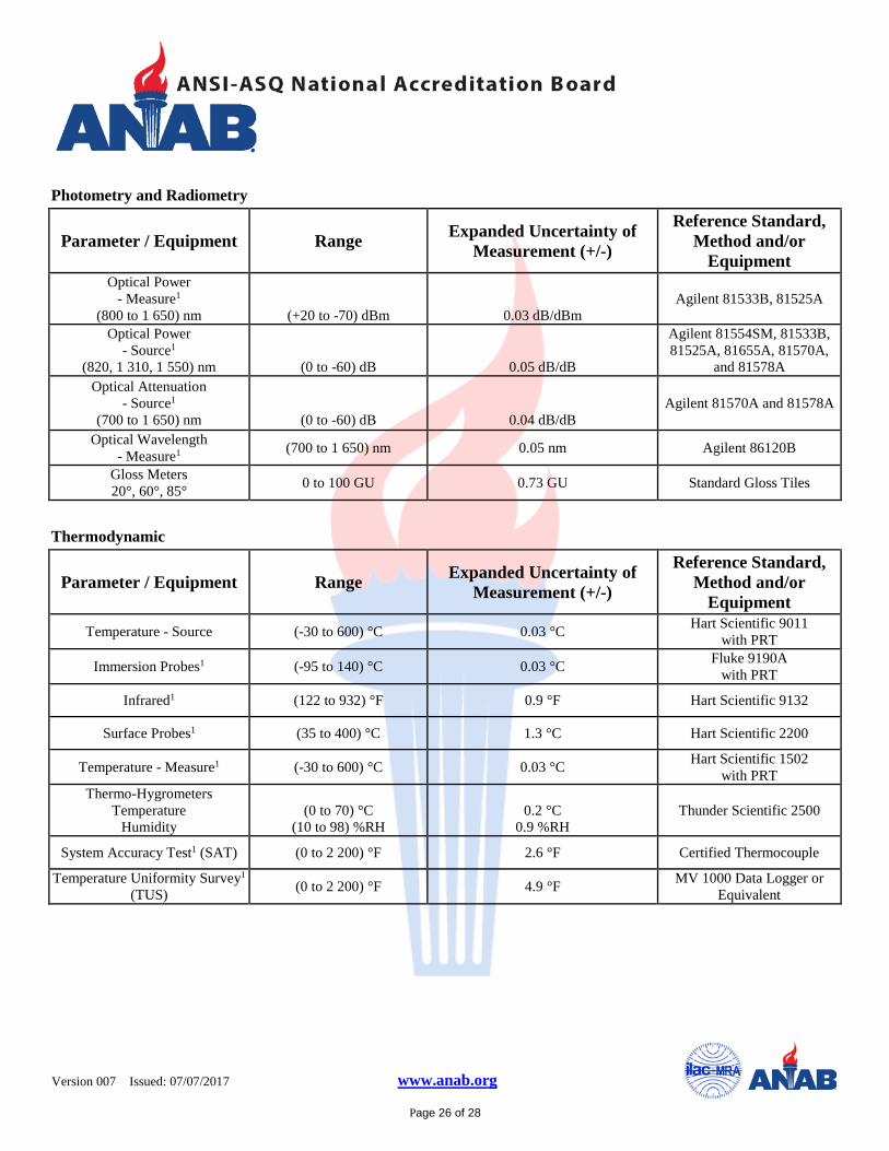
Photometry and Radiometry
Parameter / Equipment Range Expanded Uncertainty of Measurement (+/-)
Reference Standard, Method and/or
Equipment Optical Power
- Measure1 (800 to 1 650) nm
(+20 to -70) dBm
0.03 dB/dBm Agilent 81533B, 81525A
Optical Power - Source1
(820, 1 310, 1 550) nm
(0 to -60) dB
0.05 dB/dB
Agilent 81554SM, 81533B, 81525A, 81655A, 81570A,
and 81578A Optical Attenuation
- Source1 (700 to 1 650) nm
(0 to -60) dB
0.04 dB/dB Agilent 81570A and 81578A
Optical Wavelength - Measure1 (700 to 1 650) nm 0.05 nm Agilent 86120B
Gloss Meters
20°, 60°, 85° 0 to 100 GU 0.73 GU Standard Gloss Tiles
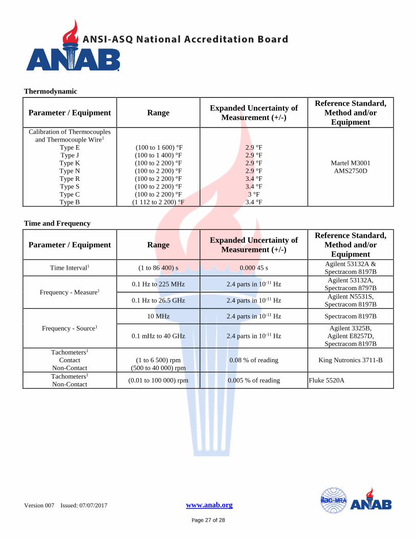
Thermodynamic
Parameter / Equipment Range Expanded Uncertainty of Measurement (+/-)
Reference Standard, Method and/or
Equipment Temperature - Source (-30 to 600) °C 0.03 °C Hart Scientific 9011
with PRT
Immersion Probes1 (-95 to 140) °C 0.03 °C Fluke 9190A with PRT
Infrared1 (122 to 932) °F 0.9 °F Hart Scientific 9132
Surface Probes1 (35 to 400) °C 1.3 °C Hart Scientific 2200
Temperature - Measure1 (-30 to 600) °C 0.03 °C Hart Scientific 1502 with PRT
Thermo-Hygrometers
Temperature Humidity
(0 to 70) °C
(10 to 98) %RH
0.2 °C
0.9 %RH Thunder Scientific 2500
System Accuracy Test1 (SAT) (0 to 2 200) °F 2.6 °F Certified Thermocouple
Temperature Uniformity Survey1 (TUS) (0 to 2 200) °F 4.9 °F MV 1000 Data Logger or
Equivalent
Version 007
Issued: 07/07/2017 www.anab.org
Page 27 of 28
Thermodynamic
Parameter / Equipment Range Expanded Uncertainty of Measurement (+/-)
Reference Standard, Method and/or
Equipment Calibration of Thermocouples
and Thermocouple Wire1
Type E Type J Type K Type N Type R Type S Type C Type B
(100 to 1 600) °F (100 to 1 400) °F (100 to 2 200) °F (100 to 2 200) °F (100 to 2 200) °F (100 to 2 200) °F (100 to 2 200) °F
(1 112 to 2 200) °F
2.9 °F 2.9 °F 2.9 °F 2.9 °F 3.4 °F 3.4 °F 3 °F
3.4 °F
Martel M3001 AMS2750D
Time and Frequency
Parameter / Equipment Range Expanded Uncertainty of Measurement (+/-)
Reference Standard, Method and/or
Equipment Time Interval1 (1 to 86 400) s 0.000 45 s Agilent 53132A &
Spectracom 8197B
Frequency - Measure1 0.1 Hz to 225 MHz 2.4 parts in 10-11 Hz Agilent 53132A,
Spectracom 8797B
0.1 Hz to 26.5 GHz 2.4 parts in 10-11 Hz Agilent N5531S, Spectracom 8197B
Frequency - Source1
10 MHz 2.4 parts in 10-11 Hz Spectracom 8197B
0.1 mHz to 40 GHz 2.4 parts in 10-11 Hz Agilent 3325B,
Agilent E8257D, Spectracom 8197B
Tachometers1
Contact
Non-Contact
(1 to 6 500) rpm
(500 to 40 000) rpm 0.08 % of reading King Nutronics 3711-B
Tachometers1
Non-Contact (0.01 to 100 000) rpm 0.005 % of reading Fluke 5520A
Version 007
Issued: 07/07/2017 www.anab.org
Page 28 of 28
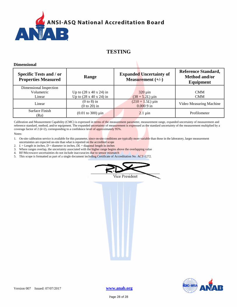
TESTING
Dimensional
Specific Tests and / or Properties Measured Range Expanded Uncertainty of
Measurement (+/-)
Reference Standard, Method and/or
Equipment Dimensional Inspection
Volumetric Linear
Up to (28 x 40 x 24) in Up to (28 x 40 x 24) in
320 µin
(38 + 5.2L) µin
CMM CMM
Linear (0 to 8) in (0 to 20) in
(210 + 1.5L) µin 0.000 9 in Video Measuring Machine
Surface Finish (Ra) (0.01 to 300) µin 2.1 µin Profilometer
Calibration and Measurement Capability (CMC) is expressed in terms of the measurement parameter, measurement range, expanded uncertainty of measurement and reference standard, method, and/or equipment. The expanded uncertainty of measurement is expressed as the standard uncertainty of the measurement multiplied by a coverage factor of 2 (k=2), corresponding to a confidence level of approximately 95%. Notes: 1. On-site calibration service is available for this parameter, since on-site conditions are typically more variable than those in the laboratory, larger measurement
uncertainties are expected on-site than what is reported on the accredited scope 2. L = Length in inches, D = diameter in inches, DL = diagonal length in inches 3. Where ranges overlap, the uncertainty associated with the higher range begins above the overlapping value 4. RF/Microwave uncertainties do not include inaccuracies due to sensor mismatch 5. This scope is formatted as part of a single document including Certificate of Accreditation No. ACT-1272.