ansa basis
DESCRIPTION
BASIC COMMANDS IN ANSATRANSCRIPT
Tutorial
BASIC ANSA
GEOMETRY CLEANUPAND SHELL MESHING
Table of Contents
1. Introduction...................................................................................................................................2 1.2. Prerequisites.........................................................................................................................2 1.3. Problem description...............................................................................................................2 1.4. Data files...............................................................................................................................2
2. Read the CAD file.........................................................................................................................3
3. Perform Cleanup...........................................................................................................................8
4. Defeaturing..................................................................................................................................37
5. Shell meshing..............................................................................................................................50
6. Conclusion..................................................................................................................................62
BETA CAE Systems S.A.

BASIC ANSA – Geometry Cleanup and Shell Meshing
1. Introduction
This tutorial presents in detail all the steps taken to read a CAD file of a part, perform cleanup, as well as some geometry simplification, in order to create a good quality shell mesh.
The steps described in this tutorial include:
• Read the IGES file with different tolerance settings and assess the results.• Cleanup geometry, close gaps, modify or create new Faces etc.• Optionally, repeat the previous step with the help of Automatic Cleanup functionality.• De-featuring, removing details such as small holes and fillets.• Mesh the parts with an element length of 10 mm• Improve the mesh by manually optimizing the shape of the Macro Areas
1.2. Prerequisites
Reading the 4 pages of section Introduction and Getting Started document is recommended in order to obtain a familiarization with the ANSA interface and terminology.
1.3. Problem description
The geometry of the part is shown here in its final state. Note that the part consists of more than one Property IDs (PIDs), as shown in different colors.
1.4. Data files
The files of this tutorial are: one IGES file named basic.igs contains the geometry and the result can be found for reference in the file basic_result.ansa .
BETA CAE Systems S.A. 2 ANSA v.13.x Tutorials
BASIC ANSA – Geometry Cleanup and Shell Meshing
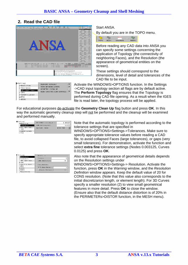
2. Read the CAD fileStart ANSA.
By default you are in the TOPO menu.
Before reading any CAD data into ANSA you can specify some settings concerning the application of Topology (the connectivity of neighboring Faces), and the Resolution (the appearance of geometrical entities on the screen).
These settings should correspond to the dimensions, level of detail and tolerances of the CAD file to be input.
Activate the WINDOWS>OPTIONS function. In the Settings->CAD input topology section all flags are by default active. The Perform Topology flag ensures that the Topology is performed during CAD file opening. As a result when the IGES file is read later, the topology process will be applied.
For educational purposes de-activate the Geometry Clean Up flag button and press OK. In this way the automatic geometry cleanup step will not be performed and the cleanup will be examined and performed manually.
Note that the automatic topology is performed according to the tolerance settings that are specified in WINDOWS>OPTIONS>Settings->Tolerances. Make sure to specify appropriate tolerance values before reading a CAD file, to avoid collapsed Faces (large tolerances), or gaps (very small tolerances). For demonstration, activate the function and select extra fine tolerance settings (Nodes 0.003125, Curves 0.0125) and press OK.
Also note that the appearance of geometrical details depends on the Resolution settings under WINDOWS>OPTIONS>Settings-> Resolution. Activate the function, press OK in the Warning window, and the Resolution Definition window appears. Keep the default value of 20 for CONS resolution. (Note that this value also corresponds to the initial discretizarion length, or element length). For 3D Curves specify a smaller resolution (2) to view small geometrical features in more detail. Press OK to close the window. (Ensure also that the default distance distortion is of 20% in the PERIMETERs>DISTOR function, in the MESH menu).
BETA CAE Systems S.A. 3 ANSA v.13.x Tutorials
BASIC ANSA – Geometry Cleanup and Shell Meshing
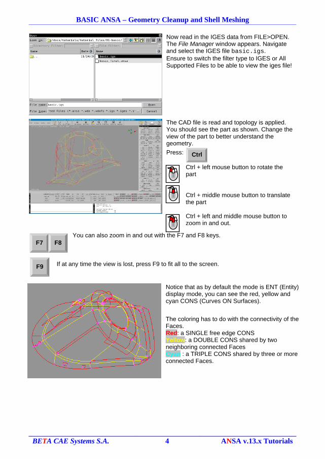
Now read in the IGES data from FILE>OPEN. The File Manager window appears. Navigate and select the IGES file basic.igs.Ensure to switch the filter type to IGES or All Supported Files to be able to view the iges file!
The CAD file is read and topology is applied. You should see the part as shown. Change the view of the part to better understand the geometry.
Press:
Ctrl + left mouse button to rotate the part
Ctrl + middle mouse button to translate the part
Ctrl + left and middle mouse button to zoom in and out.
You can also zoom in and out with the F7 and F8 keys.
If at any time the view is lost, press F9 to fit all to the screen.
Notice that as by default the mode is ENT (Entity) display mode, you can see the red, yellow and cyan CONS (Curves ON Surfaces).
The coloring has to do with the connectivity of the Faces.Red: a SINGLE free edge CONSYellow: a DOUBLE CONS shared by two neighboring connected FacesCyan : a TRIPLE CONS shared by three or more connected Faces.
BETA CAE Systems S.A. 4 ANSA v.13.x Tutorials
Ctrl
F9
F7 F8
BASIC ANSA – Geometry Cleanup and Shell Meshing
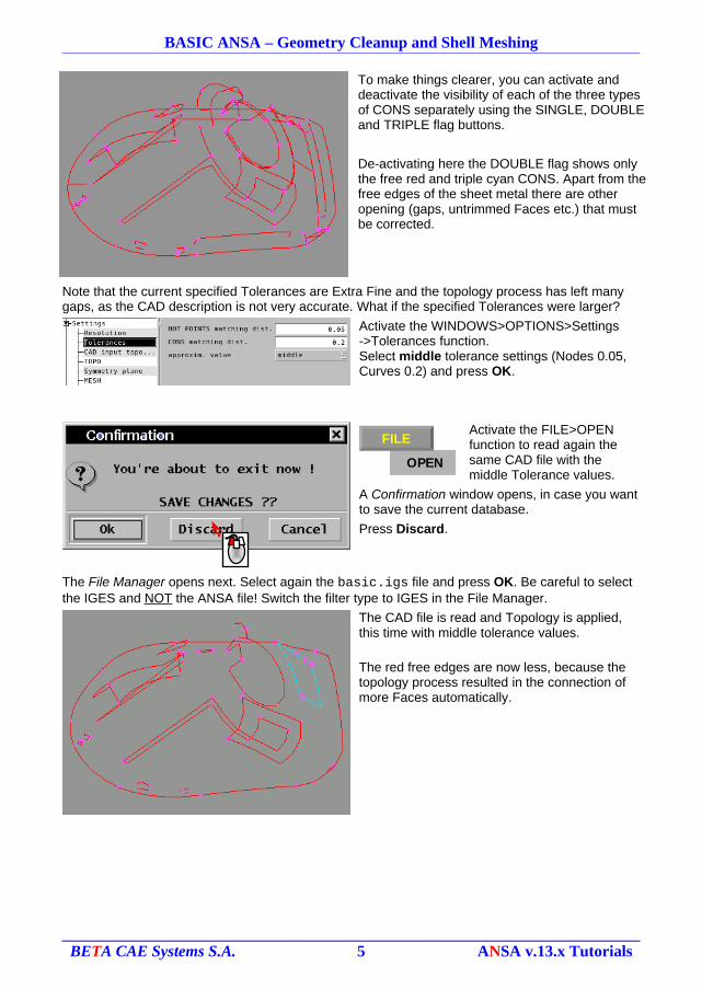
To make things clearer, you can activate and deactivate the visibility of each of the three types of CONS separately using the SINGLE, DOUBLE and TRIPLE flag buttons.
De-activating here the DOUBLE flag shows only the free red and triple cyan CONS. Apart from the free edges of the sheet metal there are other opening (gaps, untrimmed Faces etc.) that must be corrected.
Note that the current specified Tolerances are Extra Fine and the topology process has left many gaps, as the CAD description is not very accurate. What if the specified Tolerances were larger?
Activate the WINDOWS>OPTIONS>Settings->Tolerances function.Select middle tolerance settings (Nodes 0.05, Curves 0.2) and press OK.
Activate the FILE>OPEN function to read again the same CAD file with the middle Tolerance values.
A Confirmation window opens, in case you want to save the current database.
Press Discard.
The File Manager opens next. Select again the basic.igs file and press OK. Be careful to select the IGES and NOT the ANSA file! Switch the filter type to IGES in the File Manager.
The CAD file is read and Topology is applied, this time with middle tolerance values.
The red free edges are now less, because the topology process resulted in the connection of more Faces automatically.
BETA CAE Systems S.A. 5 ANSA v.13.x Tutorials
OPEN
FILE
BASIC ANSA – Geometry Cleanup and Shell Meshing
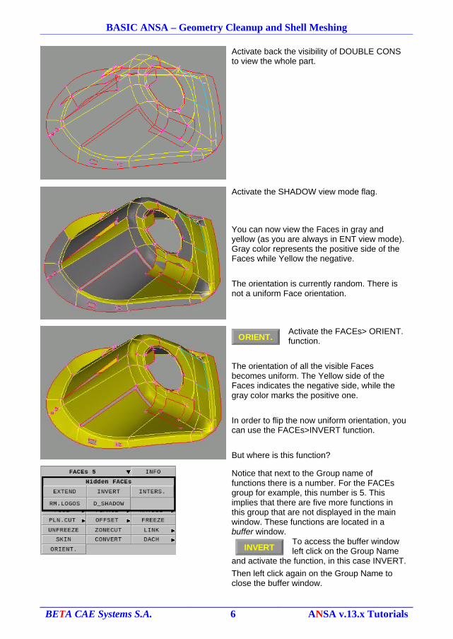
Activate back the visibility of DOUBLE CONS to view the whole part.
Activate the SHADOW view mode flag.
You can now view the Faces in gray and yellow (as you are always in ENT view mode). Gray color represents the positive side of the Faces while Yellow the negative.
The orientation is currently random. There is not a uniform Face orientation.
Activate the FACEs> ORIENT. function.
The orientation of all the visible Faces becomes uniform. The Yellow side of the Faces indicates the negative side, while the gray color marks the positive one.
In order to flip the now uniform orientation, you can use the FACEs>INVERT function.
But where is this function?
Notice that next to the Group name of functions there is a number. For the FACEs group for example, this number is 5. This implies that there are five more functions in this group that are not displayed in the main window. These functions are located in a buffer window.
To access the buffer window left click on the Group Name
and activate the function, in this case INVERT.
Then left click again on the Group Name to close the buffer window.
BETA CAE Systems S.A. 6 ANSA v.13.x Tutorials
ORIENT.
INVERT
BASIC ANSA – Geometry Cleanup and Shell Meshing
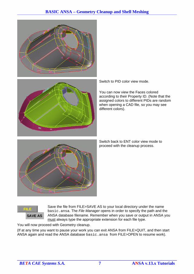
Switch to PID color view mode.
You can now view the Faces colored according to their Property ID. (Note that the assigned colors to different PIDs are random when opening a CAD file, so you may see different colors).
Switch back to ENT color view mode to proceed with the cleanup process.
Save the file from FILE>SAVE AS to your local directory under the name basic.ansa. The File Manager opens in order to specify the path and the ANSA database filename. Remember when you save or output in ANSA you must always type the appropriate extension for each file type.
You will now proceed with Geometry cleanup.
(If at any time you want to pause your work you can exit ANSA from FILE>QUIT, and then start ANSA again and read the ANSA database basic.ansa from FILE>OPEN to resume work).
BETA CAE Systems S.A. 7 ANSA v.13.x Tutorials
SAVE AS
FILE
BASIC ANSA – Geometry Cleanup and Shell Meshing
3. Perform Cleanup
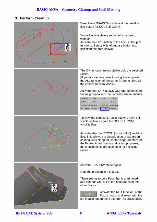
De-activate SHADOW mode and the visibility flag button for DOUBLE CONS.
You will now isolate a region of your part to work on.Activate the OR function of the Focus Group of functions. Select with left mouse button box selection the area shown.
The OR function leaves visible only the selected Faces.(If you accidentally select wrong Faces, press the ALL function of the same Group to bring all the entities back to visible).
Activate the LOCK [LOCK ON] flag button in the Focus group to lock the currently visible entities.
To view the complete Faces that you have left visible, activate again the DOUBLE CONS visibility flag.
Activate also the CROSH (cross hatch) visibility flag. This allows the visualization of two green dashed lines along the center isoparametrics of the Faces. Apart from visualization purposes, the crosshatches are also used for selecting Faces.
Activate SHADOW mode again.
Note the problem in this area.
There seems to be a Face that is untrimmed and extends well out of the boundaries of the other Faces.
Activate the NOT function, of the Focus group, and select with the
left mouse button this Face from its crosshatch.
BETA CAE Systems S.A. 8 ANSA v.13.x Tutorials
NOT
BASIC ANSA – Geometry Cleanup and Shell Meshing
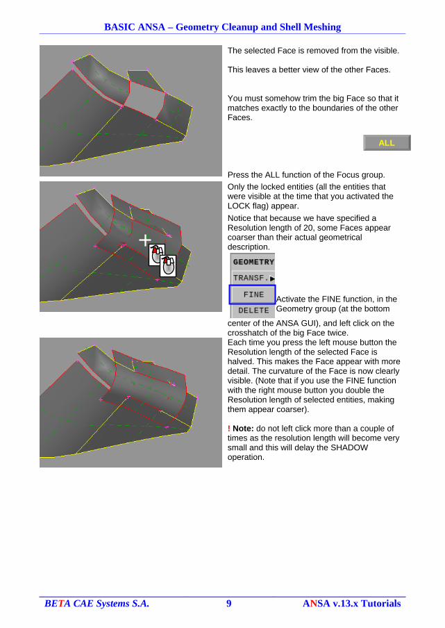
The selected Face is removed from the visible.
This leaves a better view of the other Faces.
You must somehow trim the big Face so that it matches exactly to the boundaries of the other Faces.
Press the ALL function of the Focus group.
Only the locked entities (all the entities that were visible at the time that you activated the LOCK flag) appear.
Notice that because we have specified a Resolution length of 20, some Faces appear coarser than their actual geometrical description.
Activate the FINE function, in the Geometry group (at the bottom
center of the ANSA GUI), and left click on the crosshatch of the big Face twice.
Each time you press the left mouse button the Resolution length of the selected Face is halved. This makes the Face appear with more detail. The curvature of the Face is now clearly visible. (Note that if you use the FINE function with the right mouse button you double the Resolution length of selected entities, making them appear coarser).
! Note: do not left click more than a couple of times as the resolution length will become very small and this will delay the SHADOW operation.
BETA CAE Systems S.A. 9 ANSA v.13.x Tutorials
ALL
BASIC ANSA – Geometry Cleanup and Shell Meshing
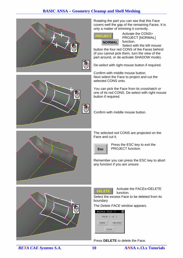
Rotating the part you can see that this Face covers well the gap of the remaining Faces. It is only a matter of trimming it correctly.
Activate the CONS> PROJECT [NORMAL] function.Select with the left mouse
button the four red CONS of the Faces behind (if you cannot pick them, turn the view of the part around, or de-activate SHADOW mode).
De-select with right mouse button if required.
Confirm with middle mouse button.
Next select the Face to project and cut the selected CONS onto.
You can pick the Face from its crosshatch or one of its red CONS. De-select with right mouse button if required.
Confirm with middle mouse button.
The selected red CONS are projected on the Face and cut it.
Press the ESC key to exit the PROJECT function.
Remember you can press the ESC key to abort any function if you are unsure.
Activate the FACEs>DELETE function.
Select the excess Face to be deleted from its boundary
The Delete FACE window appears.
Press DELETE to delete the Face.
BETA CAE Systems S.A. 10 ANSA v.13.x Tutorials
NORMAL
PROJECT
DELETE
Esc
BASIC ANSA – Geometry Cleanup and Shell Meshing
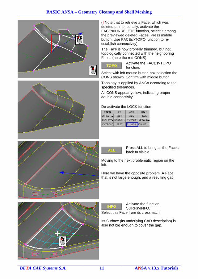
(! Note that to retrieve a Face, which was deleted unintentionally, activate the FACEs>UNDELETE function, select it among the previewed deleted Faces. Press middle button. Use FACEs>TOPO function to re-establish connectivity).
The Face is now properly trimmed, but not topologically connected with the neighboring Faces (note the red CONS).
Activate the FACEs>TOPO function.
Select with left mouse button box selection the CONS shown. Confirm with middle button.
Topology is applied by ANSA according to the specified tolerances.
All CONS appear yellow, indicating proper double connectivity.
De-activate the LOCK function
Press ALL to bring all the Faces back to visible.
Moving to the next problematic region on the left.
Here we have the opposite problem. A Face that is not large enough, and a resulting gap.
Activate the function SURFs>INFO.
Select this Face from its crosshatch.
Its Surface (its underlying CAD description) is also not big enough to cover the gap.
BETA CAE Systems S.A. 11 ANSA v.13.x Tutorials
TOPO
INFO
ALL
BASIC ANSA – Geometry Cleanup and Shell Meshing
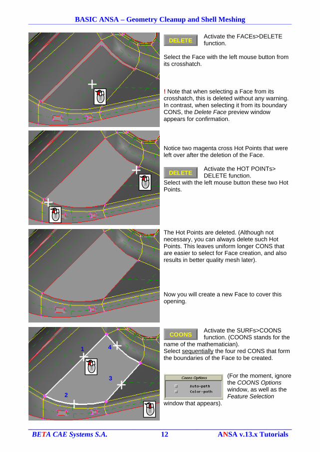
Activate the FACEs>DELETE function.
Select the Face with the left mouse button from its crosshatch.
! Note that when selecting a Face from its crosshatch, this is deleted without any warning. In contrast, when selecting it from its boundary CONS, the Delete Face preview window appears for confirmation.
Notice two magenta cross Hot Points that were left over after the deletion of the Face.
Activate the HOT POINTs> DELETE function.
Select with the left mouse button these two Hot Points.
The Hot Points are deleted. (Although not necessary, you can always delete such Hot Points. This leaves uniform longer CONS that are easier to select for Face creation, and also results in better quality mesh later).
Now you will create a new Face to cover this opening.
Activate the SURFs>COONS function. (COONS stands for the
name of the mathematician).Select sequentially the four red CONS that form the boundaries of the Face to be created.
(For the moment, ignore the COONS Options window, as well as the Feature Selection
window that appears).
BETA CAE Systems S.A. 12 ANSA v.13.x Tutorials
DELETE
DELETE
COONS
1 4
3
2
BASIC ANSA – Geometry Cleanup and Shell Meshing
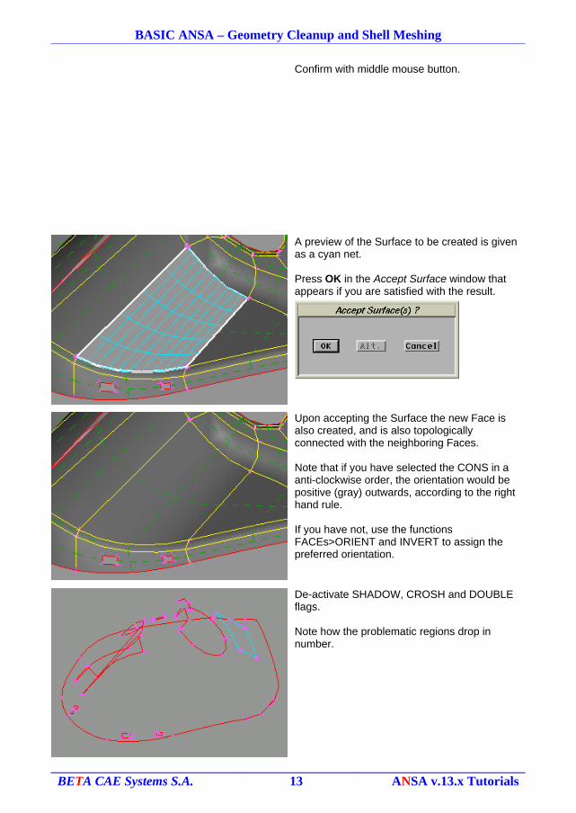
Confirm with middle mouse button.
A preview of the Surface to be created is given as a cyan net.
Press OK in the Accept Surface window that appears if you are satisfied with the result.
Upon accepting the Surface the new Face is also created, and is also topologically connected with the neighboring Faces.
Note that if you have selected the CONS in a anti-clockwise order, the orientation would be positive (gray) outwards, according to the right hand rule.
If you have not, use the functions FACEs>ORIENT and INVERT to assign the preferred orientation.
De-activate SHADOW, CROSH and DOUBLE flags.
Note how the problematic regions drop in number.
BETA CAE Systems S.A. 13 ANSA v.13.x Tutorials
BASIC ANSA – Geometry Cleanup and Shell Meshing
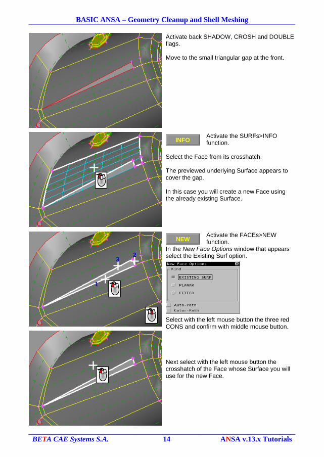
Activate back SHADOW, CROSH and DOUBLE flags.
Move to the small triangular gap at the front.
Activate the SURFs>INFO function.
Select the Face from its crosshatch.
The previewed underlying Surface appears to cover the gap.
In this case you will create a new Face using the already existing Surface.
Activate the FACEs>NEW function.
In the New Face Options window that appears select the Existing Surf option.
Select with the left mouse button the three red CONS and confirm with middle mouse button.
Next select with the left mouse button the crosshatch of the Face whose Surface you will use for the new Face.
BETA CAE Systems S.A. 14 ANSA v.13.x Tutorials
INFO
1
32
NEW
BASIC ANSA – Geometry Cleanup and Shell Meshing
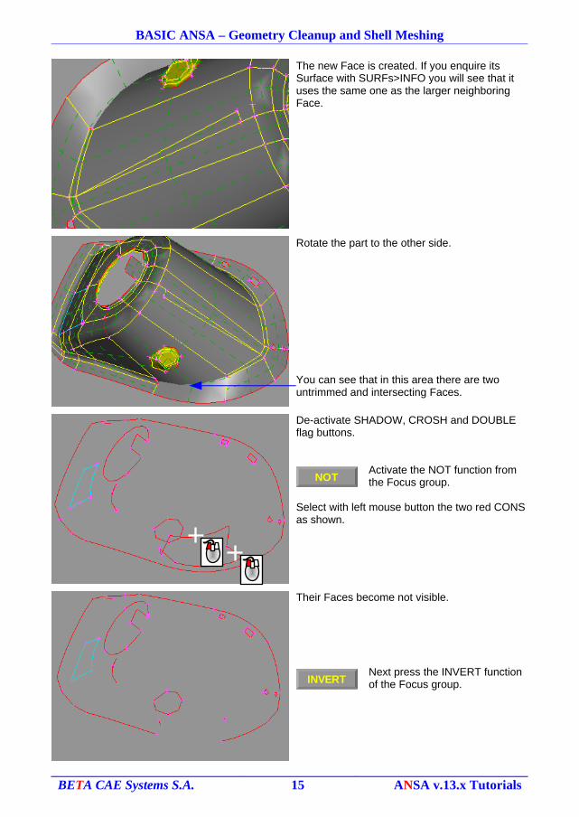
The new Face is created. If you enquire its Surface with SURFs>INFO you will see that it uses the same one as the larger neighboring Face.
Rotate the part to the other side.
You can see that in this area there are two untrimmed and intersecting Faces.
De-activate SHADOW, CROSH and DOUBLE flag buttons.
Activate the NOT function from the Focus group.
Select with left mouse button the two red CONS as shown.
Their Faces become not visible.
Next press the INVERT function of the Focus group.
BETA CAE Systems S.A. 15 ANSA v.13.x Tutorials
NOT
INVERT
BASIC ANSA – Geometry Cleanup and Shell Meshing
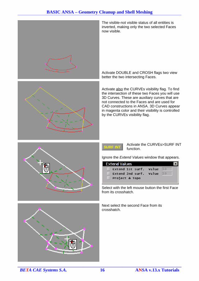
The visible-not visible status of all entities is inverted, making only the two selected Faces now visible.
Activate DOUBLE and CROSH flags two view better the two intersecting Faces.
Activate also the CURVEs visibility flag. To find the intersection of these two Faces you will use 3D Curves. These are auxiliary curves that are not connected to the Faces and are used for CAD constructions in ANSA. 3D Curves appear in magenta color and their visibility is controlled by the CURVEs visibility flag.
Activate the CURVEs>SURF INT function.
Ignore the Extend Values window that appears.
Select with the left mouse button the first Face from its crosshatch.
Next select the second Face from its crosshatch.
BETA CAE Systems S.A. 16 ANSA v.13.x Tutorials
SURF INT
BASIC ANSA – Geometry Cleanup and Shell Meshing
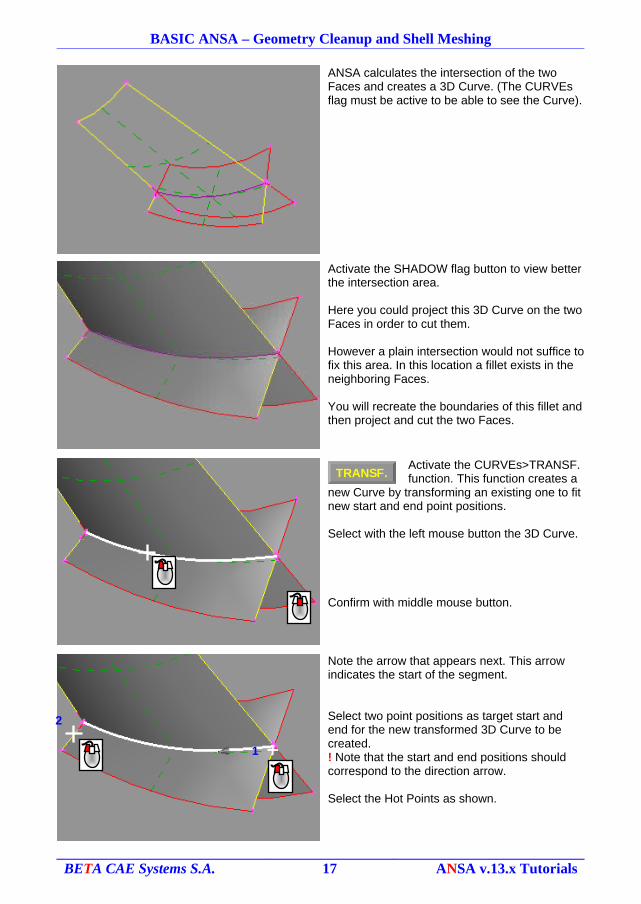
ANSA calculates the intersection of the two Faces and creates a 3D Curve. (The CURVEs flag must be active to be able to see the Curve).
Activate the SHADOW flag button to view better the intersection area.
Here you could project this 3D Curve on the two Faces in order to cut them.
However a plain intersection would not suffice to fix this area. In this location a fillet exists in the neighboring Faces.
You will recreate the boundaries of this fillet and then project and cut the two Faces.
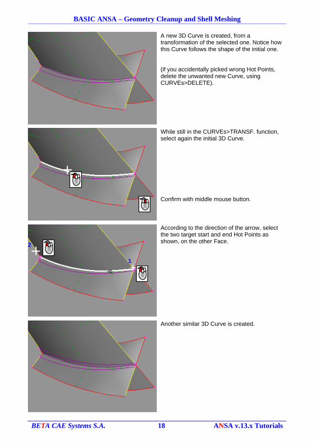
Activate the CURVEs>TRANSF. function. This function creates a
new Curve by transforming an existing one to fit new start and end point positions.
Select with the left mouse button the 3D Curve.
Confirm with middle mouse button.
Note the arrow that appears next. This arrow indicates the start of the segment.
Select two point positions as target start and end for the new transformed 3D Curve to be created. ! Note that the start and end positions should correspond to the direction arrow.
Select the Hot Points as shown.
BETA CAE Systems S.A. 17 ANSA v.13.x Tutorials
TRANSF.
2
1
BASIC ANSA – Geometry Cleanup and Shell Meshing
A new 3D Curve is created, from a transformation of the selected one. Notice how this Curve follows the shape of the initial one.
(if you accidentally picked wrong Hot Points, delete the unwanted new Curve, using CURVEs>DELETE).
While still in the CURVEs>TRANSF. function, select again the initial 3D Curve.
Confirm with middle mouse button.
According to the direction of the arrow, select the two target start and end Hot Points as shown, on the other Face.
Another similar 3D Curve is created.
BETA CAE Systems S.A. 18 ANSA v.13.x Tutorials
2
1
BASIC ANSA – Geometry Cleanup and Shell Meshing
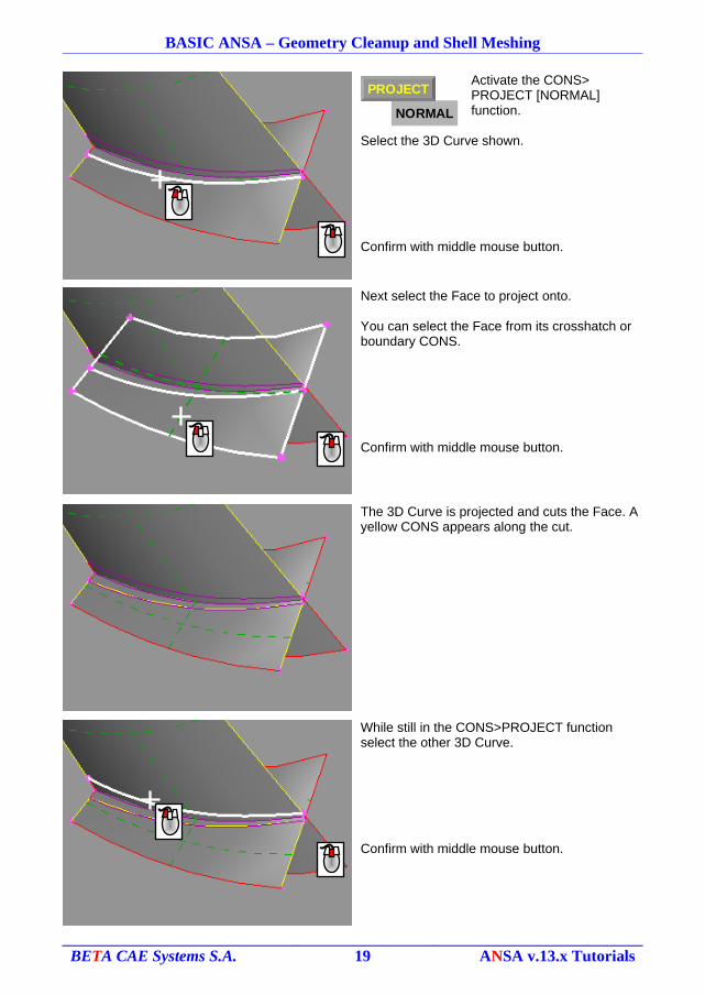
Activate the CONS> PROJECT [NORMAL] function.
Select the 3D Curve shown.
Confirm with middle mouse button.
Next select the Face to project onto.
You can select the Face from its crosshatch or boundary CONS.
Confirm with middle mouse button.
The 3D Curve is projected and cuts the Face. A yellow CONS appears along the cut.
While still in the CONS>PROJECT function select the other 3D Curve.
Confirm with middle mouse button.
BETA CAE Systems S.A. 19 ANSA v.13.x Tutorials
NORMAL
PROJECT
BASIC ANSA – Geometry Cleanup and Shell Meshing
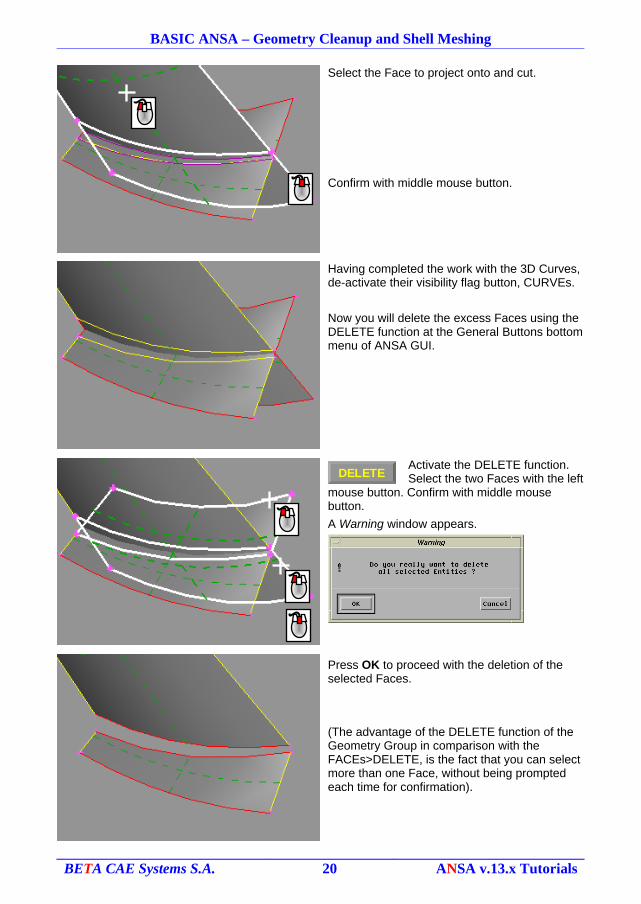
Select the Face to project onto and cut.
Confirm with middle mouse button.
Having completed the work with the 3D Curves, de-activate their visibility flag button, CURVEs.
Now you will delete the excess Faces using the DELETE function at the General Buttons bottom menu of ANSA GUI.
Activate the DELETE function.Select the two Faces with the left
mouse button. Confirm with middle mouse button.
A Warning window appears.
Press OK to proceed with the deletion of the selected Faces.
(The advantage of the DELETE function of the Geometry Group in comparison with the FACEs>DELETE, is the fact that you can select more than one Face, without being prompted each time for confirmation).
BETA CAE Systems S.A. 20 ANSA v.13.x Tutorials
DELETE
BASIC ANSA – Geometry Cleanup and Shell Meshing
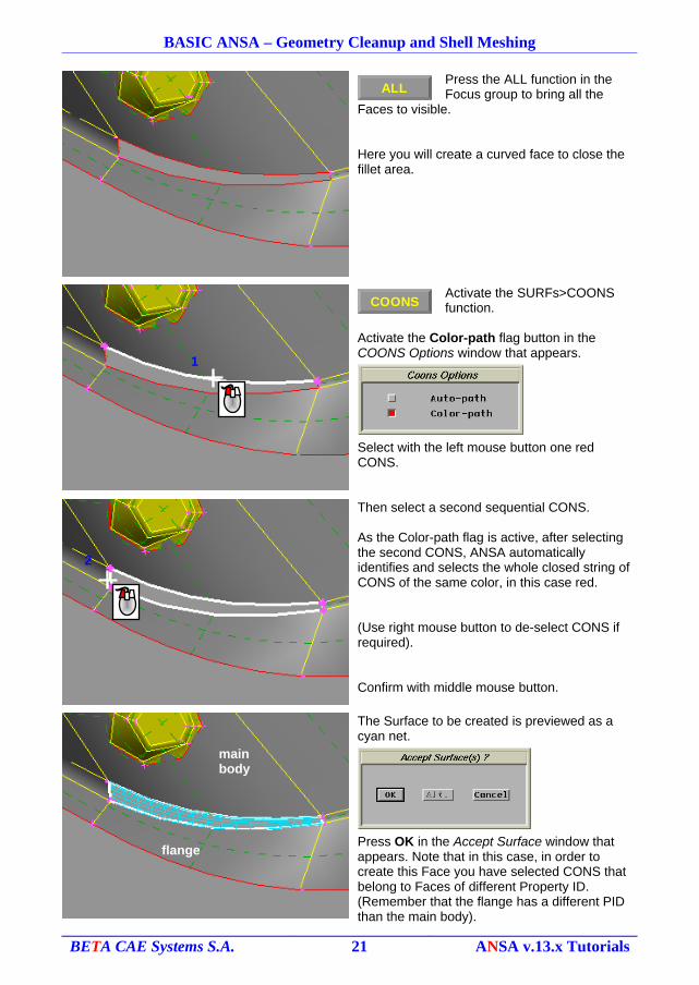
Press the ALL function in the Focus group to bring all the
Faces to visible.
Here you will create a curved face to close the fillet area.
Activate the SURFs>COONS function.
Activate the Color-path flag button in the COONS Options window that appears.
Select with the left mouse button one red CONS.
Then select a second sequential CONS.
As the Color-path flag is active, after selecting the second CONS, ANSA automatically identifies and selects the whole closed string of CONS of the same color, in this case red.
(Use right mouse button to de-select CONS if required).
Confirm with middle mouse button.
The Surface to be created is previewed as a cyan net.
Press OK in the Accept Surface window that appears. Note that in this case, in order to create this Face you have selected CONS that belong to Faces of different Property ID. (Remember that the flange has a different PID than the main body).
BETA CAE Systems S.A. 21 ANSA v.13.x Tutorials
1
2
flange
main body
ALL
COONS
BASIC ANSA – Geometry Cleanup and Shell Meshing
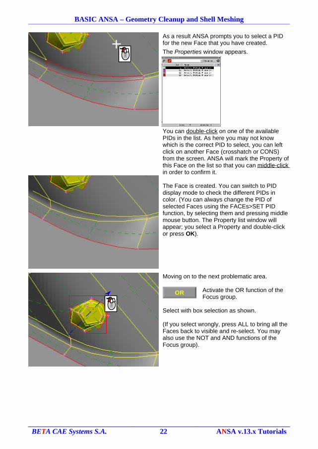
As a result ANSA prompts you to select a PID for the new Face that you have created.
The Properties window appears.
You can double-click on one of the available PIDs in the list. As here you may not know which is the correct PID to select, you can left click on another Face (crosshatch or CONS) from the screen. ANSA will mark the Property of this Face on the list so that you can middle-click in order to confirm it.
The Face is created. You can switch to PID display mode to check the different PIDs in color. (You can always change the PID of selected Faces using the FACEs>SET PID function, by selecting them and pressing middle mouse button. The Property list window will appear; you select a Property and double-click or press OK).
Moving on to the next problematic area.
Activate the OR function of the Focus group.
Select with box selection as shown.
(If you select wrongly, press ALL to bring all the Faces back to visible and re-select. You may also use the NOT and AND functions of the Focus group).
BETA CAE Systems S.A. 22 ANSA v.13.x Tutorials
OR
BASIC ANSA – Geometry Cleanup and Shell Meshing
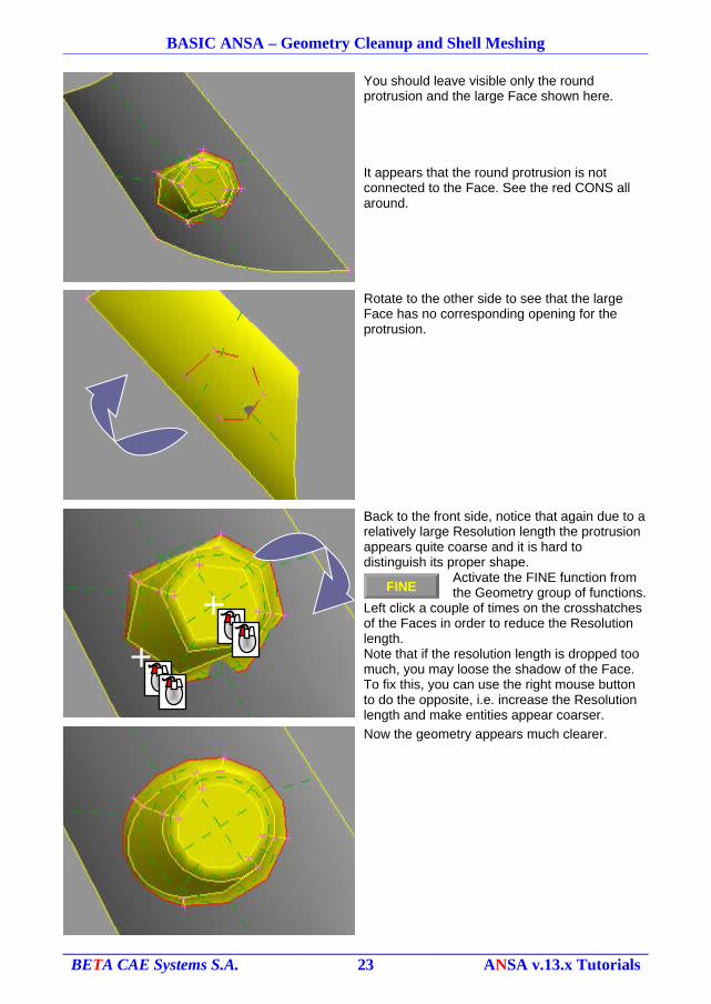
You should leave visible only the round protrusion and the large Face shown here.
It appears that the round protrusion is not connected to the Face. See the red CONS all around.
Rotate to the other side to see that the large Face has no corresponding opening for the protrusion.
Back to the front side, notice that again due to a relatively large Resolution length the protrusion appears quite coarse and it is hard to distinguish its proper shape.
Activate the FINE function from the Geometry group of functions.
Left click a couple of times on the crosshatches of the Faces in order to reduce the Resolution length.Note that if the resolution length is dropped too much, you may loose the shadow of the Face. To fix this, you can use the right mouse button to do the opposite, i.e. increase the Resolution length and make entities appear coarser.
Now the geometry appears much clearer.
BETA CAE Systems S.A. 23 ANSA v.13.x Tutorials
FINE
BASIC ANSA – Geometry Cleanup and Shell Meshing
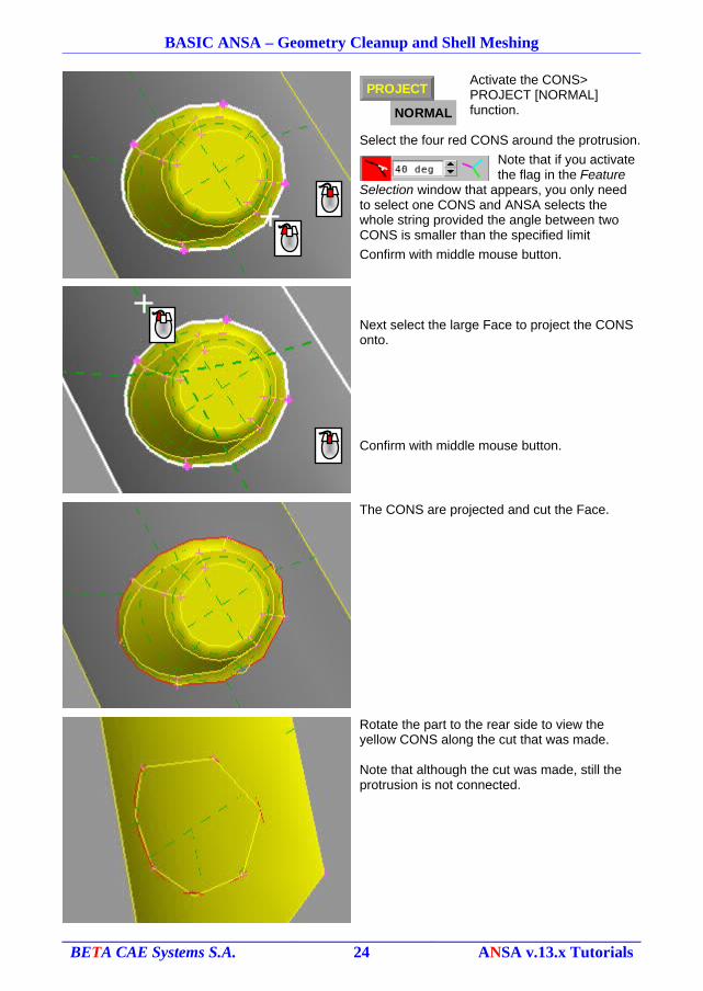
Activate the CONS> PROJECT [NORMAL] function.
Select the four red CONS around the protrusion.
Note that if you activate the flag in the Feature
Selection window that appears, you only need to select one CONS and ANSA selects the whole string provided the angle between two CONS is smaller than the specified limit
Confirm with middle mouse button.
Next select the large Face to project the CONS onto.
Confirm with middle mouse button.
The CONS are projected and cut the Face.
Rotate the part to the rear side to view the yellow CONS along the cut that was made.
Note that although the cut was made, still the protrusion is not connected.
BETA CAE Systems S.A. 24 ANSA v.13.x Tutorials
NORMAL
PROJECT
BASIC ANSA – Geometry Cleanup and Shell Meshing
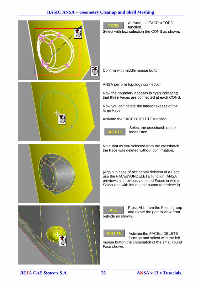
Activate the FACEs>TOPO function.
Select with box selection the CONS as shown.
Confirm with middle mouse button.
ANSA perform topology connection.
Now the boundary appears in cyan indicating that three Faces are connected at each CONS.
Now you can delete the interior excess of the large Face.
Activate the FACEs>DELETE function.
Select the crosshatch of the inner Face.
Note that as you selected from the crosshatch the Face was deleted without confirmation.
(Again in case of accidental deletion of a Face, use the FACEs>UNDELETE function. ANSA previews all previously deleted Faces in white. Select one with left mouse button to retrieve it).
Press ALL from the Focus group and rotate the part to view from
outside as shown.
Activate the FACEs>DELETE function and select with the left
mouse button the crosshatch of the small round Face shown.
BETA CAE Systems S.A. 25 ANSA v.13.x Tutorials
TOPO
DELETE
ALL
DELETE

BASIC ANSA – Geometry Cleanup and Shell Meshing
The Face is deleted without confirmation and the hole is opened.
Activate the FACEs>ORIENT function to make the orientation
of all the Faces uniform.
Moving to the next area shown here.
De-activate SHADOW, CROSH and DOUBLE flag buttons, to view the remaining gaps more easily.
Activate the OR function from the Focus group and select with box
selection the area shown.
BETA CAE Systems S.A. 26 ANSA v.13.x Tutorials
ORIENT
OR
BASIC ANSA – Geometry Cleanup and Shell Meshing
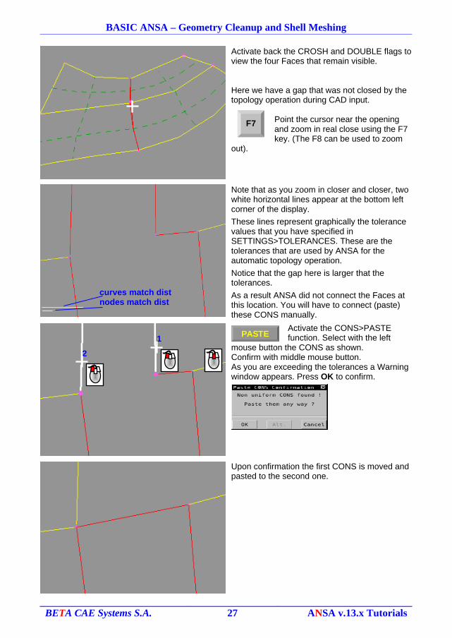
Activate back the CROSH and DOUBLE flags to view the four Faces that remain visible.
Here we have a gap that was not closed by the topology operation during CAD input.
Point the cursor near the opening and zoom in real close using the F7 key. (The F8 can be used to zoom
out).
Note that as you zoom in closer and closer, two white horizontal lines appear at the bottom left corner of the display.
These lines represent graphically the tolerance values that you have specified in SETTINGS>TOLERANCES. These are the tolerances that are used by ANSA for the automatic topology operation.
Notice that the gap here is larger that the tolerances.
As a result ANSA did not connect the Faces at this location. You will have to connect (paste) these CONS manually.
Activate the CONS>PASTE function. Select with the left
mouse button the CONS as shown.Confirm with middle mouse button.As you are exceeding the tolerances a Warning window appears. Press OK to confirm.
Upon confirmation the first CONS is moved and pasted to the second one.
BETA CAE Systems S.A. 27 ANSA v.13.x Tutorials
curves match distnodes match dist
PASTE1
2
F7
BASIC ANSA – Geometry Cleanup and Shell Meshing
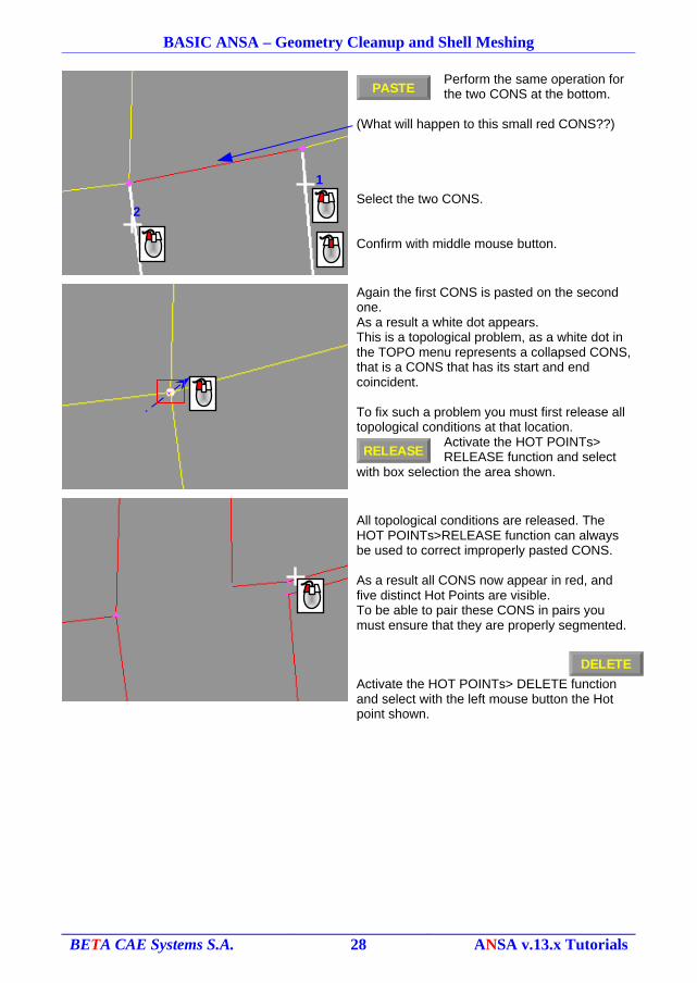
Perform the same operation for the two CONS at the bottom.
(What will happen to this small red CONS??)
Select the two CONS.
Confirm with middle mouse button.
Again the first CONS is pasted on the second one.As a result a white dot appears.This is a topological problem, as a white dot in the TOPO menu represents a collapsed CONS, that is a CONS that has its start and end coincident.
To fix such a problem you must first release all topological conditions at that location.
Activate the HOT POINTs> RELEASE function and select
with box selection the area shown.
All topological conditions are released. The HOT POINTs>RELEASE function can always be used to correct improperly pasted CONS.
As a result all CONS now appear in red, and five distinct Hot Points are visible.To be able to pair these CONS in pairs you must ensure that they are properly segmented.
Activate the HOT POINTs> DELETE function and select with the left mouse button the Hot point shown.
BETA CAE Systems S.A. 28 ANSA v.13.x Tutorials
PASTE
RELEASE
DELETE
1
2
BASIC ANSA – Geometry Cleanup and Shell Meshing
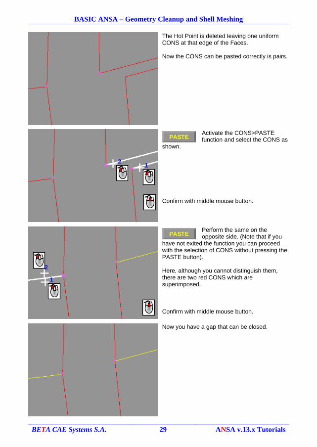
The Hot Point is deleted leaving one uniform CONS at that edge of the Faces.
Now the CONS can be pasted correctly is pairs.
Activate the CONS>PASTE function and select the CONS as
shown.
Confirm with middle mouse button.
Perform the same on the opposite side. (Note that if you
have not exited the function you can proceed with the selection of CONS without pressing the PASTE button).
Here, although you cannot distinguish them, there are two red CONS which are superimposed.
Confirm with middle mouse button.
Now you have a gap that can be closed.
BETA CAE Systems S.A. 29 ANSA v.13.x Tutorials
PASTE
PASTE
12
1
2
BASIC ANSA – Geometry Cleanup and Shell Meshing
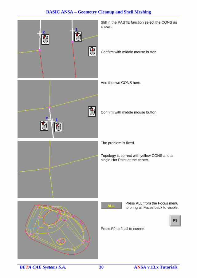
Still in the PASTE function select the CONS as shown.
Confirm with middle mouse button.
And the two CONS here.
Confirm with middle mouse button.
The problem is fixed.
Topology is correct with yellow CONS and a single Hot Point at the center.
Press ALL from the Focus menu to bring all Faces back to visible.
Press F9 to fit all to screen.
BETA CAE Systems S.A. 30 ANSA v.13.x Tutorials
12
12
F9
ALL
BASIC ANSA – Geometry Cleanup and Shell Meshing
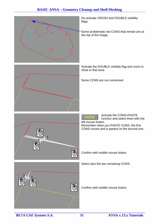
De-activate CROSH and DOUBLE visibility flags.
Some problematic red CONS that remain are at the top of the image.
Activate the DOUBLE visibility flag and zoom in close to that area.
Some CONS are not connected.
Activate the CONS>PASTE function and select them with the
left mouse button.Remember when you PASTE CONS, the first CONS moves and is pasted on the second one.
Confirm with middle mouse button.
Select also the two remaining CONS.
Confirm with middle mouse button.
BETA CAE Systems S.A. 31 ANSA v.13.x Tutorials
PASTE
12
12
BASIC ANSA – Geometry Cleanup and Shell Meshing
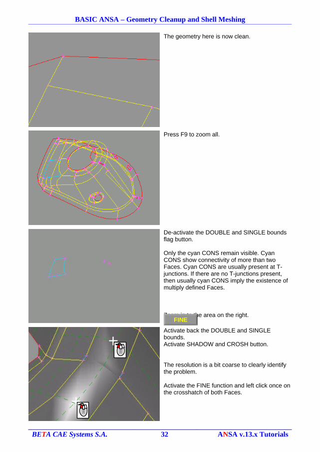
The geometry here is now clean.
Press F9 to zoom all.
De-activate the DOUBLE and SINGLE bounds flag button.
Only the cyan CONS remain visible. Cyan CONS show connectivity of more than two Faces. Cyan CONS are usually present at T-junctions. If there are no T-junctions present, then usually cyan CONS imply the existence of multiply defined Faces.
Zoom in to the area on the right.
Activate back the DOUBLE and SINGLE bounds.Activate SHADOW and CROSH button.
The resolution is a bit coarse to clearly identify the problem.
Activate the FINE function and left click once on the crosshatch of both Faces.
BETA CAE Systems S.A. 32 ANSA v.13.x Tutorials
FINE
BASIC ANSA – Geometry Cleanup and Shell Meshing
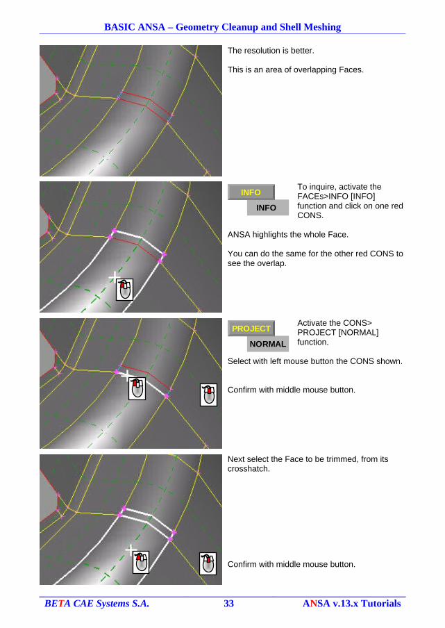
The resolution is better.
This is an area of overlapping Faces.
To inquire, activate the FACEs>INFO [INFO] function and click on one red CONS.
ANSA highlights the whole Face.
You can do the same for the other red CONS to see the overlap.
Activate the CONS> PROJECT [NORMAL] function.
Select with left mouse button the CONS shown.
Confirm with middle mouse button.
Next select the Face to be trimmed, from its crosshatch.
Confirm with middle mouse button.
BETA CAE Systems S.A. 33 ANSA v.13.x Tutorials
NORMAL
PROJECT
INFO
INFO

BASIC ANSA – Geometry Cleanup and Shell Meshing
The Face is trimmed.
Activate the FACEs>DELETE function and select the excess
Face.
Press DELETE in the Delete Face window that appears.
A gap remains.
Activate the FACEs>TOPO function, select with box selection the area and confirm with middle mouse button.
Activate the HOT PNTs>DELETE function and use
box selection to delete all remaining unnecessary Hot Points.
BETA CAE Systems S.A. 34 ANSA v.13.x Tutorials
DELETE
TOPO
DELETE
BASIC ANSA – Geometry Cleanup and Shell Meshing
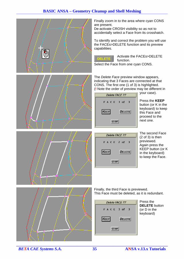
Finally zoom in to the area where cyan CONS are present.De-activate CROSH visibility so as not to accidentally select a Face from its crosshatch.
To identify and correct the problem you will use the FACEs>DELETE function and its preview capabilities.
Activate the FACEs>DELETE function.
Select the Face from one cyan CONS.
The Delete Face preview window appears, indicating that 3 Faces are connected at that CONS. The first one (1 of 3) is highlighted.(! Note the order of preview may be different in
your case).
Press the KEEP button (or K in the keyboard) to keep this Face and proceed to the next one.
The second Face (2 of 3) is then previewed.Again press the KEEP button (or K in the keyboard) to keep the Face.
Finally, the third Face is previewed.This Face must be deleted, as it is redundant.
Press the DELETE button (or D in the keyboard)
BETA CAE Systems S.A. 35 ANSA v.13.x Tutorials
DELETE
BASIC ANSA – Geometry Cleanup and Shell Meshing
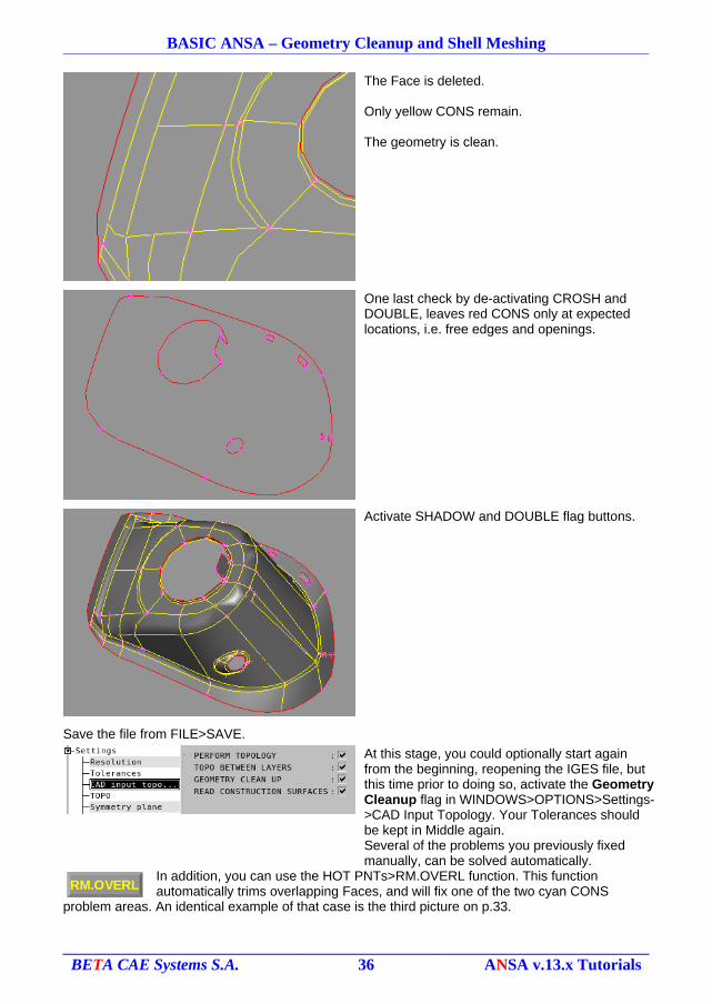
The Face is deleted.
Only yellow CONS remain.
The geometry is clean.
One last check by de-activating CROSH and DOUBLE, leaves red CONS only at expected locations, i.e. free edges and openings.
Activate SHADOW and DOUBLE flag buttons.
Save the file from FILE>SAVE.
At this stage, you could optionally start again from the beginning, reopening the IGES file, but this time prior to doing so, activate the Geometry Cleanup flag in WINDOWS>OPTIONS>Settings->CAD Input Topology. Your Tolerances should be kept in Middle again.Several of the problems you previously fixed manually, can be solved automatically.
In addition, you can use the HOT PNTs>RM.OVERL function. This function automatically trims overlapping Faces, and will fix one of the two cyan CONS
problem areas. An identical example of that case is the third picture on p.33.
BETA CAE Systems S.A. 36 ANSA v.13.x Tutorials
RM.OVERL
BASIC ANSA – Geometry Cleanup and Shell Meshing
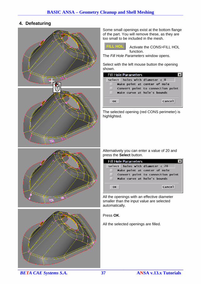
4. Defeaturing
Some small openings exist at the bottom flange of the part. You will remove these, as they are too small to be included in the mesh.
Activate the CONS>FILL HOL function.
The Fill Hole Parameters window opens.
Select with the left mouse button the opening shown.
The selected opening (red CONS perimeter) is highlighted.
Alternatively you can enter a value of 20 and press the Select button.
All the openings with an effective diameter smaller than the input value are selected automatically.
Press OK.
All the selected openings are filled.
BETA CAE Systems S.A. 37 ANSA v.13.x Tutorials
FILL HOL
BASIC ANSA – Geometry Cleanup and Shell Meshing
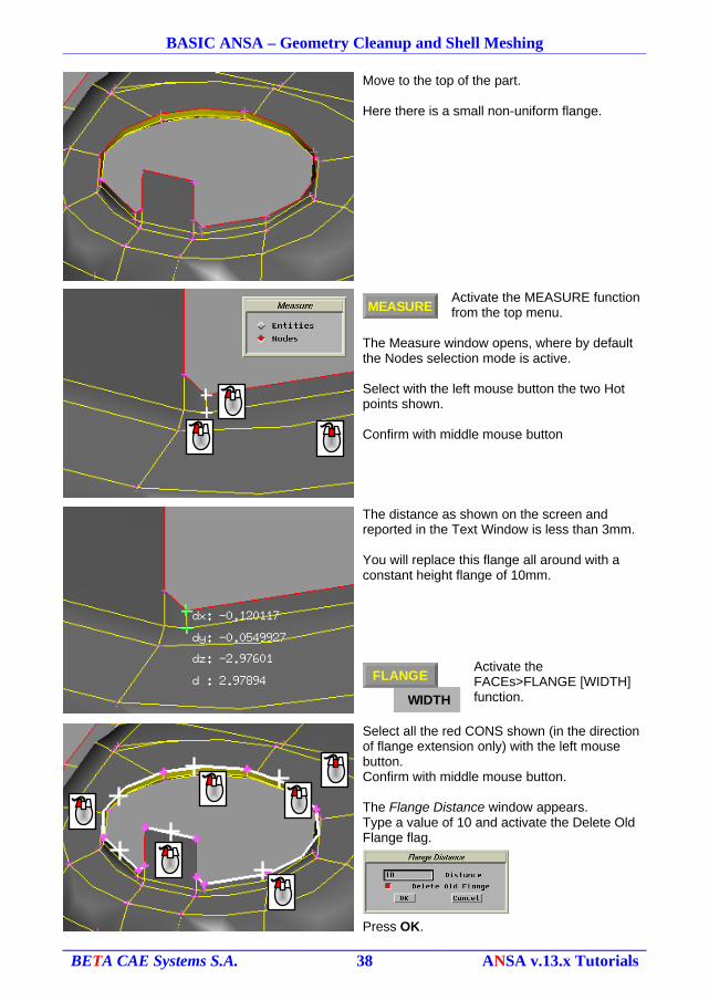
Move to the top of the part.
Here there is a small non-uniform flange.
Activate the MEASURE function from the top menu.
The Measure window opens, where by default the Nodes selection mode is active.
Select with the left mouse button the two Hot points shown.
Confirm with middle mouse button
The distance as shown on the screen and reported in the Text Window is less than 3mm.
You will replace this flange all around with a constant height flange of 10mm.
Activate the FACEs>FLANGE [WIDTH] function.
Select all the red CONS shown (in the direction of flange extension only) with the left mouse button.Confirm with middle mouse button.
The Flange Distance window appears.Type a value of 10 and activate the Delete Old Flange flag.
Press OK.
BETA CAE Systems S.A. 38 ANSA v.13.x Tutorials
MEASURE
WIDTH
FLANGE
BASIC ANSA – Geometry Cleanup and Shell Meshing
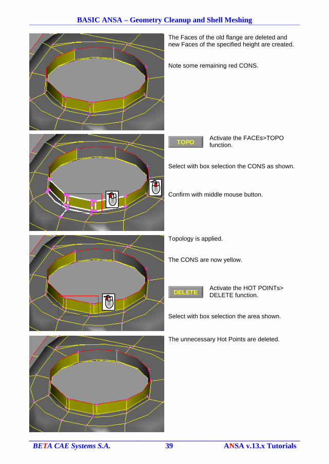
The Faces of the old flange are deleted and new Faces of the specified height are created.
Note some remaining red CONS.
Activate the FACEs>TOPO function.
Select with box selection the CONS as shown.
Confirm with middle mouse button.
Topology is applied.
The CONS are now yellow.
Activate the HOT POINTs> DELETE function.
Select with box selection the area shown.
The unnecessary Hot Points are deleted.
BETA CAE Systems S.A. 39 ANSA v.13.x Tutorials
TOPO
DELETE
BASIC ANSA – Geometry Cleanup and Shell Meshing
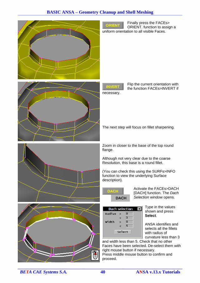
Finally press the FACEs> ORIENT. function to assign a
uniform orientation to all visible Faces.
Flip the current orientation with the function FACEs>INVERT if
necessary.
The next step will focus on fillet sharpening.
Zoom in closer to the base of the top round flange.
Although not very clear due to the coarse Resolution, this base is a round fillet.
(You can check this using the SURFs>INFO function to view the underlying Surface description).
Activate the FACEs>DACH [DACH] function. The Dach Selection window opens.
Type in the values shown and press Select.
ANSA identifies and selects all the fillets with radius of curvature less than 3
and width less than 5. Check that no other Faces have been selected. De-select them with right mouse button if necessary.Press middle mouse button to confirm and proceed.
BETA CAE Systems S.A. 40 ANSA v.13.x Tutorials
ORIENT
INVERT
DACH
DACH
BASIC ANSA – Geometry Cleanup and Shell Meshing
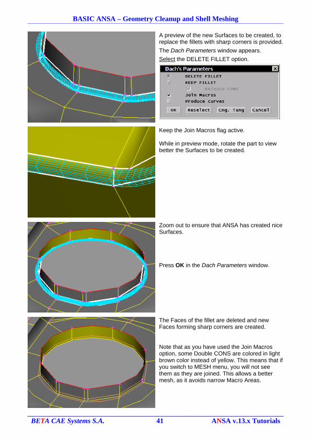
A preview of the new Surfaces to be created, to replace the fillets with sharp corners is provided.
The Dach Parameters window appears.
Select the DELETE FILLET option.
Keep the Join Macros flag active.
While in preview mode, rotate the part to view better the Surfaces to be created.
Zoom out to ensure that ANSA has created nice Surfaces.
Press OK in the Dach Parameters window.
The Faces of the fillet are deleted and new Faces forming sharp corners are created.
Note that as you have used the Join Macros option, some Double CONS are colored in light brown color instead of yellow. This means that if you switch to MESH menu, you will not see them as they are joined. This allows a better mesh, as it avoids narrow Macro Areas.
BETA CAE Systems S.A. 41 ANSA v.13.x Tutorials
BASIC ANSA – Geometry Cleanup and Shell Meshing
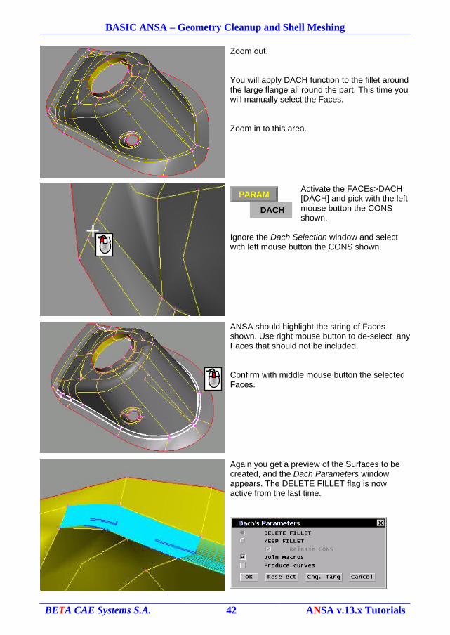
Zoom out.
You will apply DACH function to the fillet around the large flange all round the part. This time you will manually select the Faces.
Zoom in to this area.
Activate the FACEs>DACH [DACH] and pick with the left mouse button the CONS shown.
Ignore the Dach Selection window and select with left mouse button the CONS shown.
ANSA should highlight the string of Faces shown. Use right mouse button to de-select any Faces that should not be included.
Confirm with middle mouse button the selected Faces.
Again you get a preview of the Surfaces to be created, and the Dach Parameters window appears. The DELETE FILLET flag is now active from the last time.
BETA CAE Systems S.A. 42 ANSA v.13.x Tutorials
DACH
PARAMDACH
BASIC ANSA – Geometry Cleanup and Shell Meshing
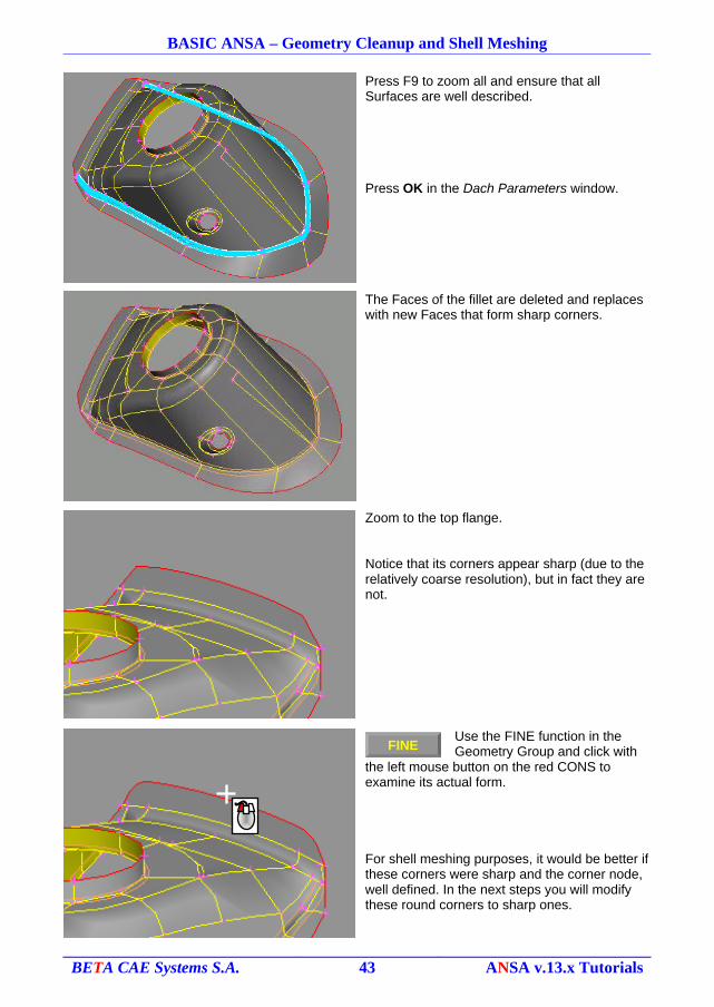
Press F9 to zoom all and ensure that all Surfaces are well described.
Press OK in the Dach Parameters window.
The Faces of the fillet are deleted and replaces with new Faces that form sharp corners.
Zoom to the top flange.
Notice that its corners appear sharp (due to the relatively coarse resolution), but in fact they are not.
Use the FINE function in the Geometry Group and click with
the left mouse button on the red CONS to examine its actual form.
For shell meshing purposes, it would be better if these corners were sharp and the corner node, well defined. In the next steps you will modify these round corners to sharp ones.
BETA CAE Systems S.A. 43 ANSA v.13.x Tutorials
FINE
BASIC ANSA – Geometry Cleanup and Shell Meshing
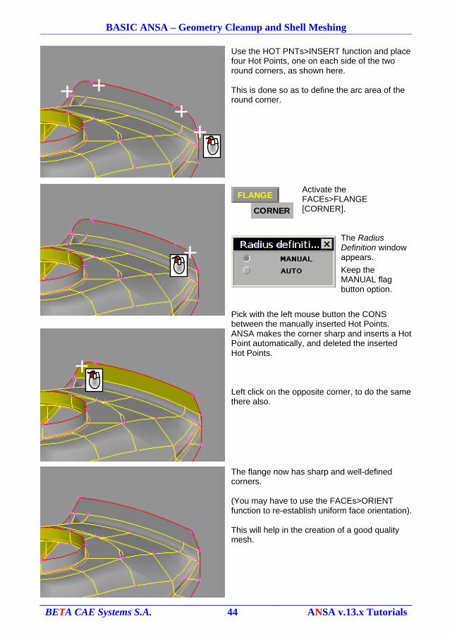
Use the HOT PNTs>INSERT function and place four Hot Points, one on each side of the two round corners, as shown here.
This is done so as to define the arc area of the round corner.
Activate the FACEs>FLANGE [CORNER].
The Radius Definition window appears.
Keep the MANUAL flag button option.
Pick with the left mouse button the CONS between the manually inserted Hot Points.
ANSA makes the corner sharp and inserts a Hot Point automatically, and deleted the inserted Hot Points.
Left click on the opposite corner, to do the same there also.
The flange now has sharp and well-defined corners.
(You may have to use the FACEs>ORIENT function to re-establish uniform face orientation).
This will help in the creation of a good quality mesh.
BETA CAE Systems S.A. 44 ANSA v.13.x Tutorials
CORNER
FLANGE
BASIC ANSA – Geometry Cleanup and Shell Meshing
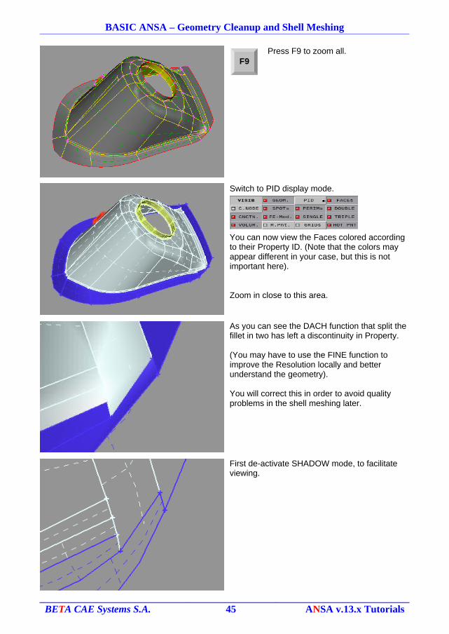
Press F9 to zoom all.
Switch to PID display mode.
You can now view the Faces colored according to their Property ID. (Note that the colors may appear different in your case, but this is not important here).
Zoom in close to this area.
As you can see the DACH function that split the fillet in two has left a discontinuity in Property.
(You may have to use the FINE function to improve the Resolution locally and better understand the geometry).
You will correct this in order to avoid quality problems in the shell meshing later.
First de-activate SHADOW mode, to facilitate viewing.
BETA CAE Systems S.A. 45 ANSA v.13.x Tutorials
F9
BASIC ANSA – Geometry Cleanup and Shell Meshing
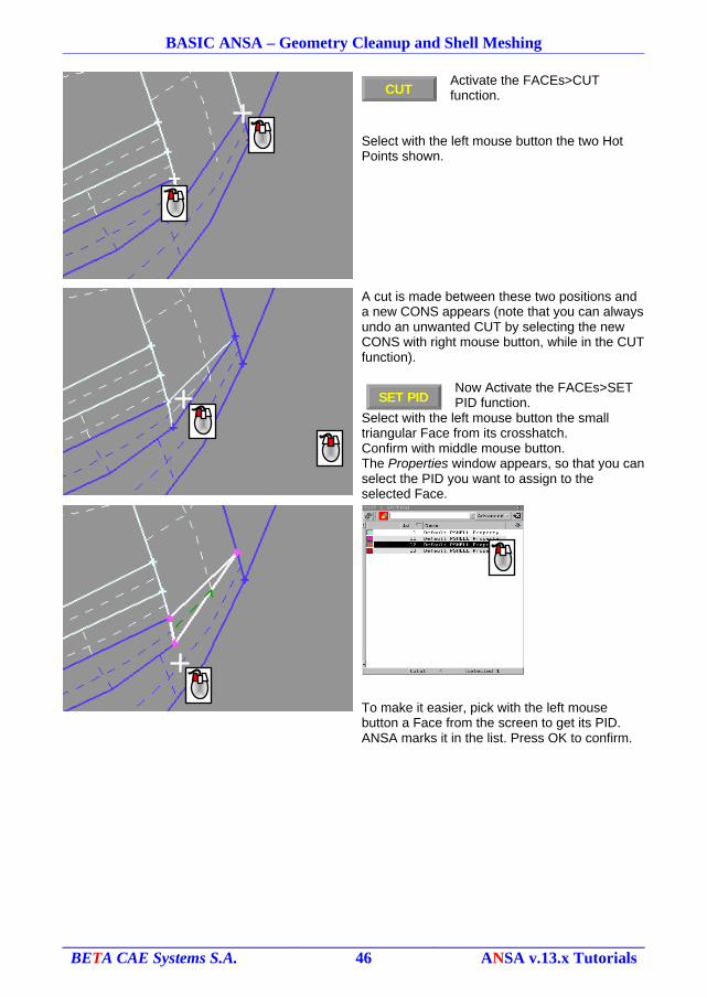
Activate the FACEs>CUT function.
Select with the left mouse button the two Hot Points shown.
A cut is made between these two positions and a new CONS appears (note that you can always undo an unwanted CUT by selecting the new CONS with right mouse button, while in the CUT function).
Now Activate the FACEs>SET PID function.
Select with the left mouse button the small triangular Face from its crosshatch.Confirm with middle mouse button.The Properties window appears, so that you can select the PID you want to assign to the selected Face.
To make it easier, pick with the left mouse button a Face from the screen to get its PID. ANSA marks it in the list. Press OK to confirm.
BETA CAE Systems S.A. 46 ANSA v.13.x Tutorials
CUT
SET PID
BASIC ANSA – Geometry Cleanup and Shell Meshing
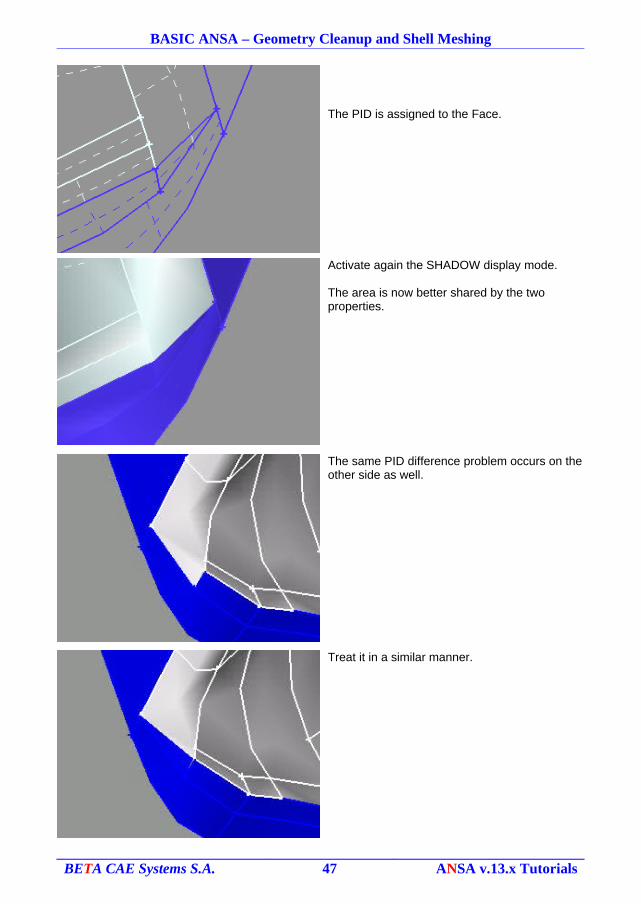
The PID is assigned to the Face.
Activate again the SHADOW display mode.
The area is now better shared by the two properties.
The same PID difference problem occurs on the other side as well.
Treat it in a similar manner.
BETA CAE Systems S.A. 47 ANSA v.13.x Tutorials
BASIC ANSA – Geometry Cleanup and Shell Meshing
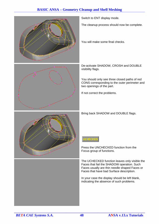
Switch to ENT display mode.
The cleanup process should now be complete.
You will make some final checks.
De-activate SHADOW, CROSH and DOUBLE visibility flags.
You should only see three closed paths of red CONS corresponding to the outer perimeter and two openings of the part.
If not correct the problems.
Bring back SHADOW and DOUBLE flags.
Press the UNCHECKED function from the Focus group of functions.
The UCHECKED function leaves only visible the Faces that fail the SHADOW operation. Such Faces usually are thin needle shaped Faces or Faces that have bad Surface description.
In your case the display should be left blank, indicating the absence of such problems.
BETA CAE Systems S.A. 48 ANSA v.13.x Tutorials
UCHECKED
BASIC ANSA – Geometry Cleanup and Shell Meshing
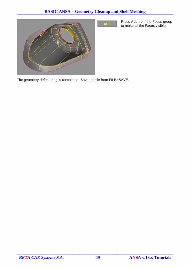
Press ALL from the Focus group to make all the Faces visible.
The geometry defeaturing is completed. Save the file from FILE>SAVE.
BETA CAE Systems S.A. 49 ANSA v.13.x Tutorials
ALL
BASIC ANSA – Geometry Cleanup and Shell Meshing
5. Shell meshing
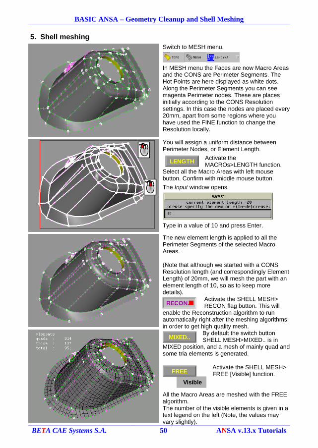
Switch to MESH menu.
In MESH menu the Faces are now Macro Areas and the CONS are Perimeter Segments. The Hot Points are here displayed as white dots. Along the Perimeter Segments you can see magenta Perimeter nodes. These are places initially according to the CONS Resolution settings. In this case the nodes are placed every 20mm, apart from some regions where you have used the FINE function to change the Resolution locally.
You will assign a uniform distance between Perimeter Nodes, or Element Length.
Activate the MACROs>LENGTH function.
Select all the Macro Areas with left mouse button. Confirm with middle mouse button.
The Input window opens.
Type in a value of 10 and press Enter.
The new element length is applied to all the Perimeter Segments of the selected Macro Areas.
(Note that although we started with a CONS Resolution length (and correspondingly Element Length) of 20mm, we will mesh the part with an element length of 10, so as to keep more details).
Activate the SHELL MESH> RECON flag button. This will
enable the Reconstruction algorithm to run automatically right after the meshing algorithms, in order to get high quality mesh.
By default the switch button SHELL MESH>MIXED.. is in
MIXED position, and a mesh of mainly quad and some tria elements is generated.
Activate the SHELL MESH> FREE [Visible] function.
All the Macro Areas are meshed with the FREE algorithm.The number of the visible elements is given in a text legend on the left (Note, the values may vary slightly).
BETA CAE Systems S.A. 50 ANSA v.13.x Tutorials
LENGTH
RECON.
Visible
FREE
MIXED..
BASIC ANSA – Geometry Cleanup and Shell Meshing
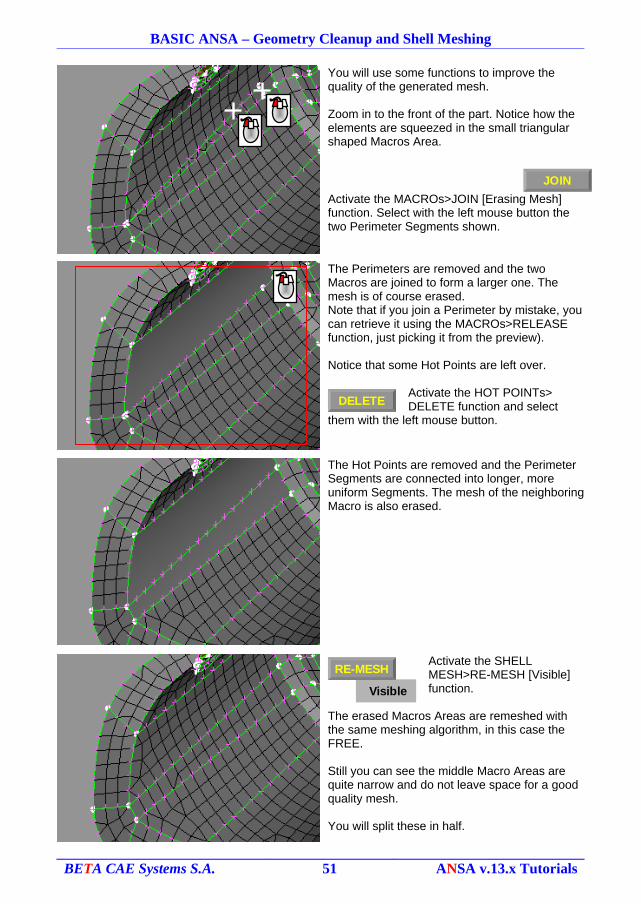
You will use some functions to improve the quality of the generated mesh.
Zoom in to the front of the part. Notice how the elements are squeezed in the small triangular shaped Macros Area.
Activate the MACROs>JOIN [Erasing Mesh] function. Select with the left mouse button the two Perimeter Segments shown.
The Perimeters are removed and the two Macros are joined to form a larger one. The mesh is of course erased.Note that if you join a Perimeter by mistake, you can retrieve it using the MACROs>RELEASE function, just picking it from the preview).
Notice that some Hot Points are left over.
Activate the HOT POINTs> DELETE function and select
them with the left mouse button.
The Hot Points are removed and the Perimeter Segments are connected into longer, more uniform Segments. The mesh of the neighboring Macro is also erased.
Activate the SHELL MESH>RE-MESH [Visible] function.
The erased Macros Areas are remeshed with the same meshing algorithm, in this case the FREE.
Still you can see the middle Macro Areas are quite narrow and do not leave space for a good quality mesh.
You will split these in half.
BETA CAE Systems S.A. 51 ANSA v.13.x Tutorials
JOIN
DELETE
Visible
RE-MESH
BASIC ANSA – Geometry Cleanup and Shell Meshing
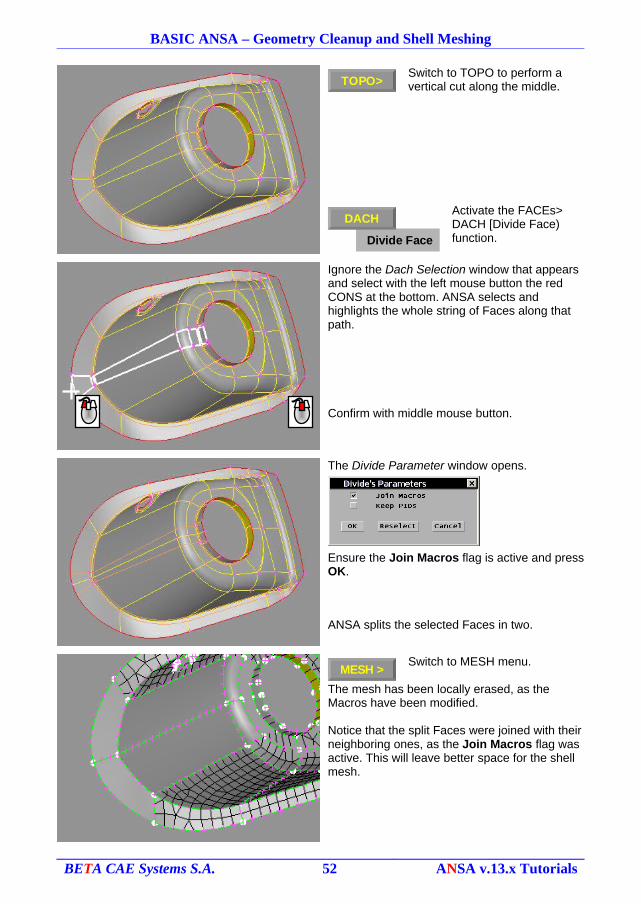
Switch to TOPO to perform a vertical cut along the middle.
Activate the FACEs> DACH [Divide Face) function.
Ignore the Dach Selection window that appears and select with the left mouse button the red CONS at the bottom. ANSA selects and highlights the whole string of Faces along that path.
Confirm with middle mouse button.
The Divide Parameter window opens.
Ensure the Join Macros flag is active and press OK.
ANSA splits the selected Faces in two.
Switch to MESH menu.
The mesh has been locally erased, as the Macros have been modified.
Notice that the split Faces were joined with their neighboring ones, as the Join Macros flag was active. This will leave better space for the shell mesh.
BETA CAE Systems S.A. 52 ANSA v.13.x Tutorials
TOPO>
MESH >DACH
Divide Face
DACH
BASIC ANSA – Geometry Cleanup and Shell Meshing
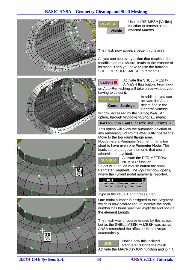
Use the RE-MESH [Visible] function to remesh all the affected Macros.
The mesh now appears better in this area.
As you can see every action that results in the modification of a Macro, leads to the erasure of its mesh. Then you have to use the function SHELL MESH>RE-MESH to remesh it.
Activate the SHELL MESH> A.MESH flag button. From now
on Auto-Remeshing will take place without you having to select it.
In addition, you can activate the Auto-delete flag in the General Settings
window accessed by the Settings>MESH option, through Windows>Options... menu:
This option will allow the automatic deletion of any remaining Hot Points after JOIN operations.Move to the top round flange area.
Notice here a Perimeter Segment that is too short to have even one Perimeter Node. This leads some triangular elements that could otherwise be avoided.
Activate the PERIMETERs> NUMBER function.
Select with the left mouse button the small Perimeter Segment. The Input window opens, where the current nodal number is reported.
Type in the value 1 and press Enter.
One nodal number is assigned to this Segment, which is now colored red, to indicate the nodal number has been specified explicitly and not via the element Length.
The mesh was of course erased by this action, but as the SHELL MESH>A.MESH was active, ANSA remeshed the affected Macro Areas automatically.
Notice how this inclined Perimeter distorts the mesh.
Activate the MACROs>JOIN function and join it.
BETA CAE Systems S.A. 53 ANSA v.13.x Tutorials
A.MESH
NUMBER
JOIN
Visible
RE-MESH
Genral Settings
SETTINGS
BASIC ANSA – Geometry Cleanup and Shell Meshing
The mesh is better.
Move to the other side of the top flange.A similar problem exists here also.
Activate the PERIMETERs> NUMBER function and apply a
nodal number of one.
The mesh is improved here as well.
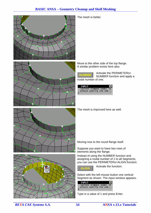
Moving now to the round flange itself.
Suppose you want to have two rows of elements along the flange.
Instead of using the NUMBER function and assigning a nodal number of 1 to all Segments, you can use the PERIMETERs>ALIGN function.
Activate the function.
Select with the left mouse button one vertical Segment as shown. The Input window appears.
Type in a value of 1 and press Enter.
BETA CAE Systems S.A. 54 ANSA v.13.x Tutorials
NUMBER
ALIGN
BASIC ANSA – Geometry Cleanup and Shell Meshing
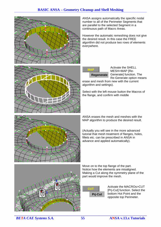
ANSA assigns automatically the specific nodal number to all of the Perimeter Segments that are parallel to the selected Segment in a continuous path of Macro Areas.
However the automatic remeshing does not give the desired result. In this case the FREE algorithm did not produce two rows of elements everywhere.
Activate the SHELL MESH>MAP [Re-Generate] function. The Re-Generate option means
erase and mesh from new with the current algorithm and settings).
Select with the left mouse button the Macros of the flange, and confirm with middle
ANSA erases the mesh and meshes with the MAP algorithm to produce the desired result.
(Actually you will see in the more advanced tutorial that mesh treatment of flanges, holes, fillets etc. can be prescribed in ANSA in advance and applied automatically).
Move on to the top flange of the part.Notice how the elements are misaligned. Making a Cut along the symmetry plane of the part would improve the mesh.
Activate the MACROs>CUT [Prj-Cut] function. Select the bottom Hot Point and the opposite top Perimeter.
BETA CAE Systems S.A. 55 ANSA v.13.x Tutorials
1
2
Prj-Cut
CUT
Regenerate
MAP
BASIC ANSA – Geometry Cleanup and Shell Meshing
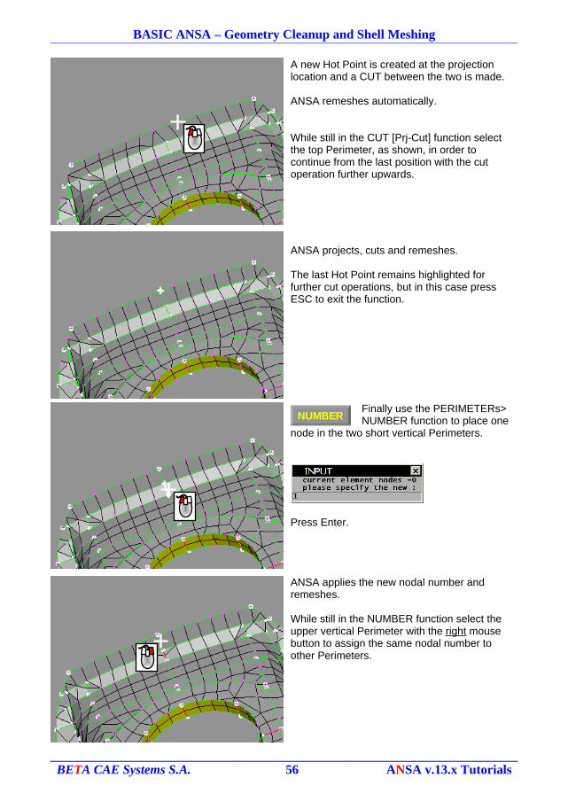
A new Hot Point is created at the projection location and a CUT between the two is made.
ANSA remeshes automatically.
While still in the CUT [Prj-Cut] function select the top Perimeter, as shown, in order to continue from the last position with the cut operation further upwards.
ANSA projects, cuts and remeshes.
The last Hot Point remains highlighted for further cut operations, but in this case press ESC to exit the function.
Finally use the PERIMETERs> NUMBER function to place one
node in the two short vertical Perimeters.
Press Enter.
ANSA applies the new nodal number and remeshes.
While still in the NUMBER function select the upper vertical Perimeter with the right mouse button to assign the same nodal number to other Perimeters.
BETA CAE Systems S.A. 56 ANSA v.13.x Tutorials
NUMBER
BASIC ANSA – Geometry Cleanup and Shell Meshing
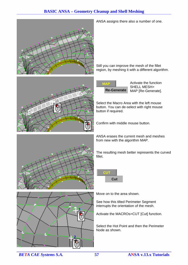
ANSA assigns there also a number of one.
Still you can improve the mesh of the fillet region, by meshing it with a different algorithm.
Activate the functionSHELL MESH>MAP [Re-Generate].
Select the Macro Area with the left mouse button. You can de-select with right mouse button if required.
Confirm with middle mouse button.
ANSA erases the current mesh and meshes from new with the algorithm MAP.
The resulting mesh better represents the curved fillet.
Move on to the area shown.
See how this tilted Perimeter Segment interrupts the orientation of the mesh.
Activate the MACROs>CUT [Cut] function.
Select the Hot Point and then the Perimeter Node as shown.
BETA CAE Systems S.A. 57 ANSA v.13.x Tutorials
Re-Generate
MAP
Cut
CUT
1
2
BASIC ANSA – Geometry Cleanup and Shell Meshing
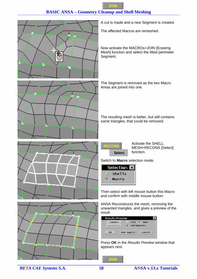
A cut is made and a new Segment is created.
The affected Macros are remeshed.
Now activate the MACROs>JOIN [Erasimg Mesh] function and select the tilted perimeter Segment.
The Segment is removed as the two Macro Areas are joined into one.
The resulting mesh is better, but still contains some triangles, that could be removed.
Activate the SHELL MESH>RECONS [Select] function.
Switch to Macro selection mode.
Then select with left mouse button this Macro and confirm with middle mouse button.
ANSA Reconstructs the mesh, removing the unwanted triangles, and gives a preview of the result.
Press OK in the Results Preview window that appears next.
BETA CAE Systems S.A. 58 ANSA v.13.x Tutorials
JOIN
JOIN
Select
RECONS
BASIC ANSA – Geometry Cleanup and Shell Meshing
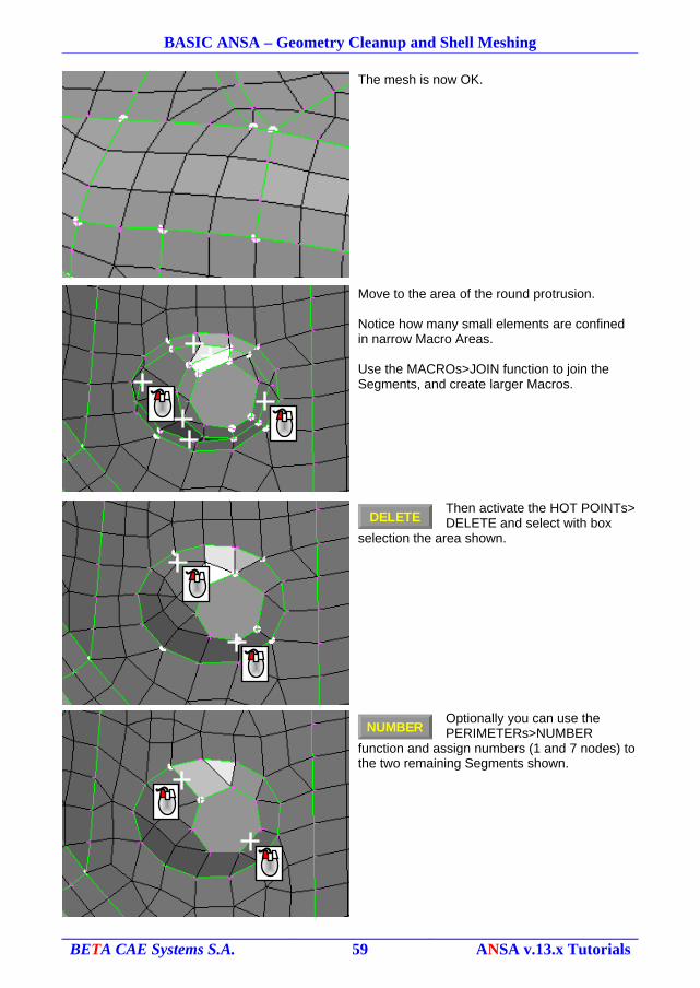
The mesh is now OK.
Move to the area of the round protrusion.
Notice how many small elements are confined in narrow Macro Areas.
Use the MACROs>JOIN function to join the Segments, and create larger Macros.
Then activate the HOT POINTs> DELETE and select with box
selection the area shown.
Optionally you can use the PERIMETERs>NUMBER
function and assign numbers (1 and 7 nodes) to the two remaining Segments shown.
BETA CAE Systems S.A. 59 ANSA v.13.x Tutorials
DELETE
NUMBER
BASIC ANSA – Geometry Cleanup and Shell Meshing
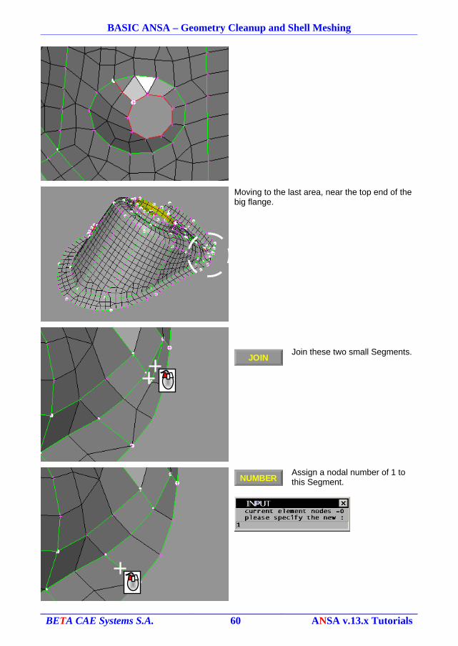
Moving to the last area, near the top end of the big flange.
Join these two small Segments.
Assign a nodal number of 1 to this Segment.
BETA CAE Systems S.A. 60 ANSA v.13.x Tutorials
JOIN
NUMBER
BASIC ANSA – Geometry Cleanup and Shell Meshing
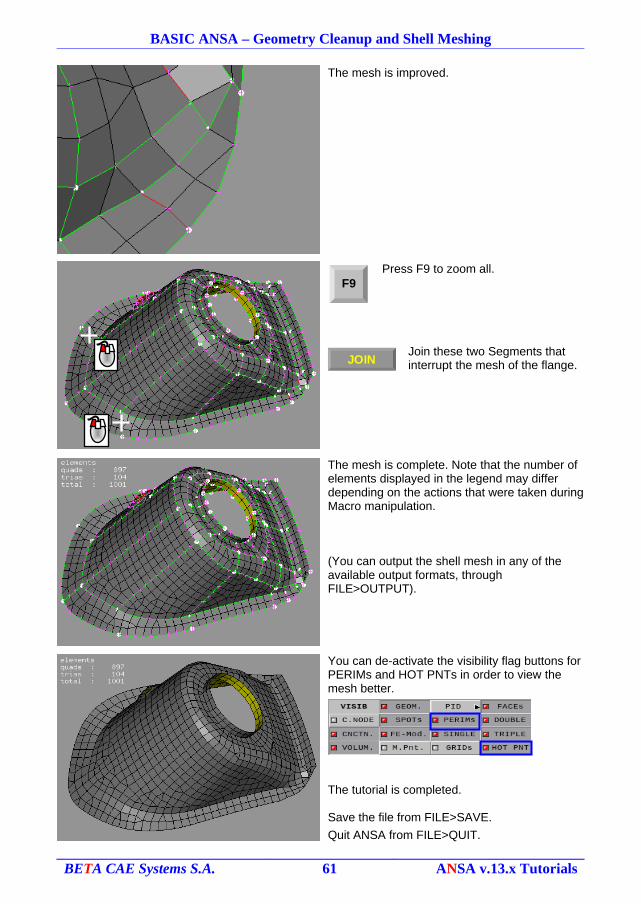
The mesh is improved.
Press F9 to zoom all.
Join these two Segments that interrupt the mesh of the flange.
The mesh is complete. Note that the number of elements displayed in the legend may differ depending on the actions that were taken during Macro manipulation.
(You can output the shell mesh in any of the available output formats, through FILE>OUTPUT).
You can de-activate the visibility flag buttons for PERIMs and HOT PNTs in order to view the mesh better.
The tutorial is completed.
Save the file from FILE>SAVE.
Quit ANSA from FILE>QUIT.
BETA CAE Systems S.A. 61 ANSA v.13.x Tutorials
F9
JOIN
BASIC ANSA – Geometry Cleanup and Shell Meshing
! Having quit ANSA, you may, or may not, want to delete the ANSA.defaults file that you have created from the main menu: Windows > Options... > Settings > 'Save settings to ANSA.defaults' icon. This file is located in your home directory. You can otherwise specify a different directory by selecting the 'Save settings as...' icon. Changes that may have occurred in the Graphics User Interface may be saved in the ANSA.xml file, by selecting the corresponding icon from: Windows > Options... > GUI Settings group icon option.Deleting the corresponding files will ensure that the next time you start ANSA, it will appear with its inherent default settings.
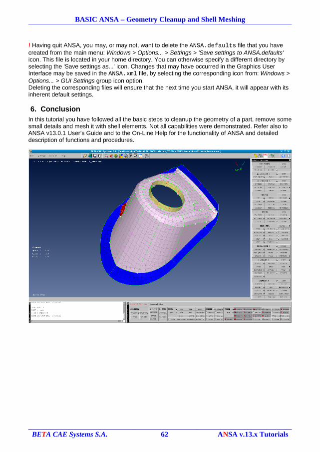
6. ConclusionIn this tutorial you have followed all the basic steps to cleanup the geometry of a part, remove some small details and mesh it with shell elements. Not all capabilities were demonstrated. Refer also to ANSA v13.0.1 User’s Guide and to the On-Line Help for the functionality of ANSA and detailed description of functions and procedures.
BETA CAE Systems S.A. 62 ANSA v.13.x Tutorials