annual peer - review meetingmicrosoft powerpoint - das.ppt author: dragla created date: 12/12/2005...
TRANSCRIPT
This document contains information proprietary to AEP. It shall not be reproduced in whole or in part or released to any third party without expressed written consent of AEP.
Annual Peer Annual Peer -- Review Meeting Review Meeting
2020thth October 2005October 2005
Debosmita Das and Dave Nichols Debosmita Das and Dave Nichols
Power Conversion System (PCS)Power Conversion System (PCS)

This document contains information proprietary to AEP. It shall not be reproduced in whole or in part or released to any third party without expressed written consent of AEP.
ACKNOWLEDGMENTSACKNOWLEDGMENTS
Funded in part by the Energy Storage Systems Program of the U.S.Department Of Energy (DOE/ESS) through Sandia National Laboratories (SNL).

This document contains information proprietary to AEP. It shall not be reproduced in whole or in part or released to any third party without expressed written consent of AEP.
Topics of DiscussionTopics of Discussion
Introduction
Characteristics and Features
3-Level Inverter
Recommended Future Paths
Our Partners

This document contains information proprietary to AEP. It shall not be reproduced in whole or in part or released to any third party without expressed written consent of AEP.
IntroductionIntroduction
0 0.002 0.004 0.006 0.008 0.01 0.012 0.014 0.016-300
-200
-100
0
100
200
300
Time (s)
Va(
t), V
b(t),
Vc(
t)
LOC
AL U
SER
INTE
RFA
CE
RE
MO
TE U
SER
INTE
RFA
CE
DC
BUS
CA
PAC
ITOR
IND
UC
TOR
CO
NTAC
TOR
FUSE
125Vac/dcto 24Vdc
MPS Board
UCB
Gate Drive V-I-T sense
24Vdc Battery
HeatsinkBusbarVdc
kVdc
time
DC Voltage
IGBT
125Vdc Station Power
CONTROL BOX
BIDIRECTIONAL INVERTER
100kVA PCS TANK
DSP-BDSP-A
ALTERA
This document contains information proprietary to AEP. It shall not be reproduced in whole or in part or released to any third party without expressed written consent of AEP.
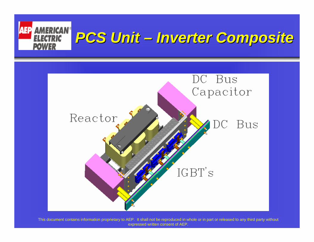
PCS Unit PCS Unit –– Inverter CompositeInverter Composite

This document contains information proprietary to AEP. It shall not be reproduced in whole or in part or released to any third party without expressed written consent of AEP.
PCS PCS -- SpecificationsSpecifications
• Low cost PCS ($50/kW) for the utility applications.
• Varying output voltage (480V/240V/208V) depending on the
input DC bus voltage.
• DC bus voltage range from 800-1600 V.
• AC output current of 120 Arms (100 kW).
• Efficiency around 98%.

This document contains information proprietary to AEP. It shall not be reproduced in whole or in part or released to any third party without expressed written consent of AEP.
PCS PCS -- CharacteristicsCharacteristics
• Capable of operating in parallel.
• Inject and sink active and reactive power from the system.
• Reliable for all power system operations.
• Capable of both indoor and outdoor operations.
• Modular device facilitating bench-top assembly.

This document contains information proprietary to AEP. It shall not be reproduced in whole or in part or released to any third party without expressed written consent of AEP.
PCS Unit PCS Unit –– ComponentsComponents
Eupec’s Dual Pack IGBT Module
IGBT Modules Mounted on Heat Sink
This document contains information proprietary to AEP. It shall not be reproduced in whole or in part or released to any third party without expressed written consent of AEP.
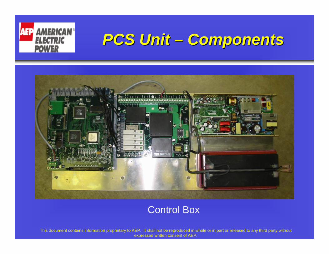
PCS Unit PCS Unit –– ComponentsComponents
Control Box

This document contains information proprietary to AEP. It shall not be reproduced in whole or in part or released to any third party without expressed written consent of AEP.
PCS Unit PCS Unit –– ComponentsComponents
Universal Control Board (UCB)
Main Power Supply (MPS)
This document contains information proprietary to AEP. It shall not be reproduced in whole or in part or released to any third party without expressed written consent of AEP.
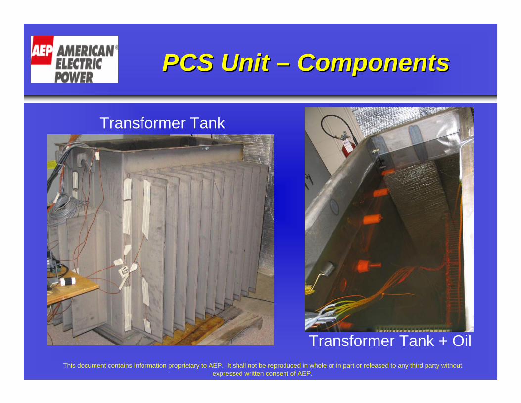
Transformer Tank
Transformer Tank + Oil
PCS Unit PCS Unit –– ComponentsComponents

This document contains information proprietary to AEP. It shall not be reproduced in whole or in part or released to any third party without expressed written consent of AEP.
20 kW PCS20 kW PCS
• Sandia National Lab is currently reviewing the 20 kW prototype.
• The unit demonstrated bi-directional power flow using both active and reactive power.
• The unit also demonstrated functionality with a PV array.
This document contains information proprietary to AEP. It shall not be reproduced in whole or in part or released to any third party without expressed written consent of AEP.
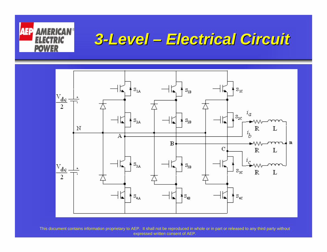
33--Level Level –– Electrical CircuitElectrical Circuit

This document contains information proprietary to AEP. It shall not be reproduced in whole or in part or released to any third party without expressed written consent of AEP.
Why choose 3Why choose 3--Level Inverter?Level Inverter?
• Switching frequency for a 3-level inverter is reduced to about ¼th of that of a 2-level inverter.
• Switching loss is lower because of reduced switching frequency.
• Losses are more evenly distributed in double the number of IGBTs.
• Distribution of losses helps in * Eliminating the hot spots.* Enhancing heat dissipation from the IGBTs.* Reducing thermal gradient.
This document contains information proprietary to AEP. It shall not be reproduced in whole or in part or released to any third party without expressed written consent of AEP.
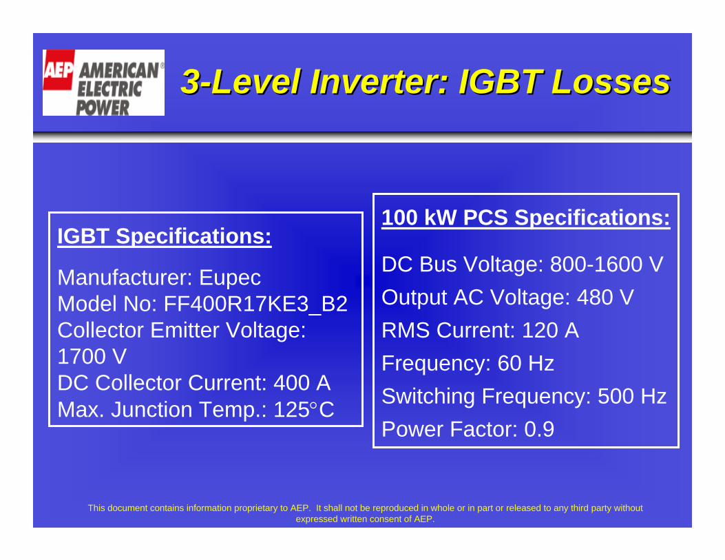
33--Level Inverter: IGBT LossesLevel Inverter: IGBT Losses
IGBT Specifications:
Manufacturer: EupecModel No: FF400R17KE3_B2Collector Emitter Voltage: 1700 VDC Collector Current: 400 AMax. Junction Temp.: 125°C
100 kW PCS Specifications:
DC Bus Voltage: 800-1600 VOutput AC Voltage: 480 VRMS Current: 120 AFrequency: 60 HzSwitching Frequency: 500 HzPower Factor: 0.9
This document contains information proprietary to AEP. It shall not be reproduced in whole or in part or released to any third party without expressed written consent of AEP.
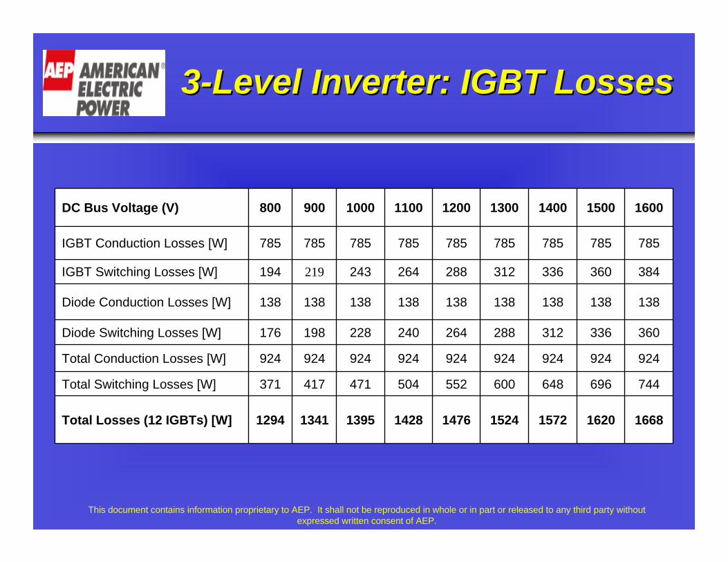
33--Level Inverter: IGBT LossesLevel Inverter: IGBT Losses
166816201572152414761428139513411294Total Losses (12 IGBTs) [W]
744696648600552504471417371Total Switching Losses [W]
924924924924924924924924924Total Conduction Losses [W]
360336312288264240228198176Diode Switching Losses [W]
138138138138138138138138138Diode Conduction Losses [W]
384360336312288264243219194IGBT Switching Losses [W]
785785785785785785785785785IGBT Conduction Losses [W]
1600150014001300120011001000900800DC Bus Voltage (V)
This document contains information proprietary to AEP. It shall not be reproduced in whole or in part or released to any third party without expressed written consent of AEP.
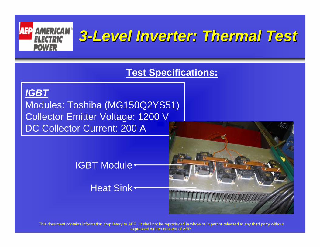
33--Level Inverter: Thermal TestLevel Inverter: Thermal Test
IGBTModules: Toshiba (MG150Q2YS51)Collector Emitter Voltage: 1200 VDC Collector Current: 200 A
IGBT Module
Heat Sink
Test Specifications:
This document contains information proprietary to AEP. It shall not be reproduced in whole or in part or released to any third party without expressed written consent of AEP.
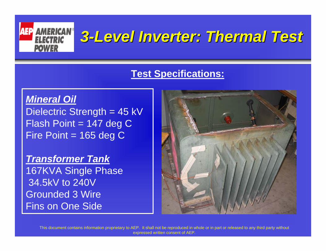
33--Level Inverter: Thermal TestLevel Inverter: Thermal Test
Mineral OilDielectric Strength = 45 kV Flash Point = 147 deg CFire Point = 165 deg C
Transformer Tank167KVA Single Phase34.5kV to 240VGrounded 3 WireFins on One Side
Test Specifications:
This document contains information proprietary to AEP. It shall not be reproduced in whole or in part or released to any third party without expressed written consent of AEP.
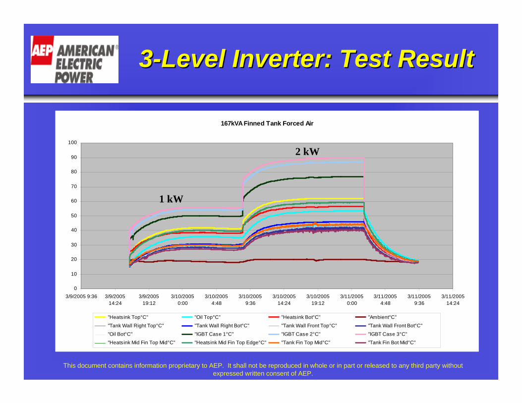
167kVA Finned Tank Forced Air
0
10
20
30
40
50
60
70
80
90
100
3/9/2005 9:36 3/9/200514:24
3/9/200519:12
3/10/20050:00
3/10/20054:48
3/10/20059:36
3/10/200514:24
3/10/200519:12
3/11/20050:00
3/11/20054:48
3/11/20059:36
3/11/200514:24
"Heatsink Top°C" "Oil Top°C" "Heatsink Bot°C" "Ambient°C"
"Tank Wall Right Top°C" "Tank Wall Right Bot°C" "Tank Wall Front Top°C" "Tank Wall Front Bot°C"
"Oil Bot°C" "IGBT Case 1°C" "IGBT Case 2°C" "IGBT Case 3°C" "Heatsink Mid Fin Top Mid°C" "Heatsink Mid Fin Top Edge°C" "Tank Fin Top Mid°C" "Tank Fin Bot Mid°C"
1 kW
2 kW
33--Level Inverter: Test ResultLevel Inverter: Test Result

This document contains information proprietary to AEP. It shall not be reproduced in whole or in part or released to any third party without expressed written consent of AEP.
Inverter: Thermal Simulation Inverter: Thermal Simulation

This document contains information proprietary to AEP. It shall not be reproduced in whole or in part or released to any third party without expressed written consent of AEP.
33--Level Inverter : ConclusionsLevel Inverter : Conclusions
• The 3-level PCS can be designed for DC bus voltage range of 800-
1600 V.
• Output AC voltage will be 480V and rms current 120 A. To
dissipate a total loss of 2 kW an 100 kVA transformer tank with fins
on three sides can be used.
• Estimated amount of oil required to cool such a system is less than
100 gallons.
From the simulations and thermal test carried out on the 100 kW,
3-level PCS design it was concluded that :
This document contains information proprietary to AEP. It shall not be reproduced in whole or in part or released to any third party without expressed written consent of AEP.
33--Level Inverter : Cost EstimateLevel Inverter : Cost Estimate
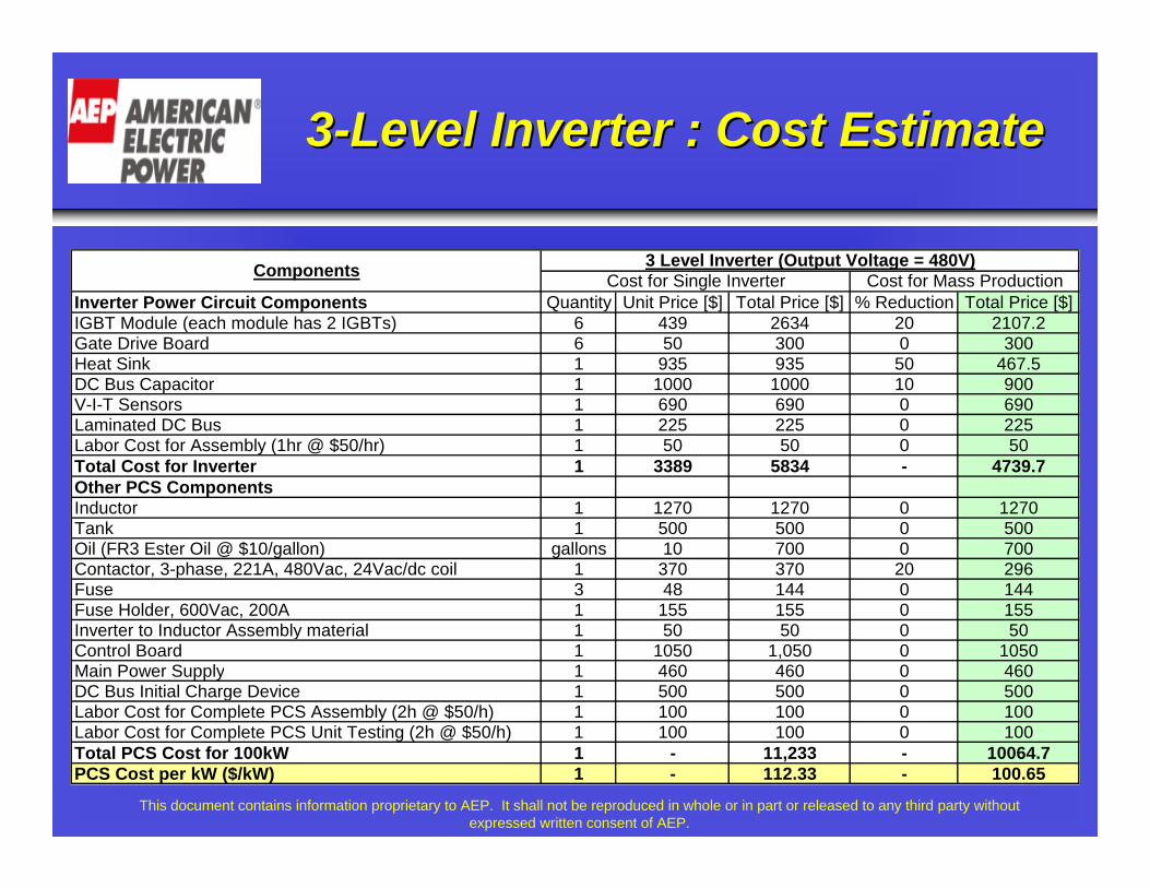
Inverter Power Circuit Components Quantity Unit Price [$] Total Price [$] % Reduction Total Price [$]IGBT Module (each module has 2 IGBTs) 6 439 2634 20 2107.2Gate Drive Board 6 50 300 0 300Heat Sink 1 935 935 50 467.5DC Bus Capacitor 1 1000 1000 10 900V-I-T Sensors 1 690 690 0 690Laminated DC Bus 1 225 225 0 225Labor Cost for Assembly (1hr @ $50/hr) 1 50 50 0 50Total Cost for Inverter 1 3389 5834 - 4739.7Other PCS ComponentsInductor 1 1270 1270 0 1270Tank 1 500 500 0 500Oil (FR3 Ester Oil @ $10/gallon) gallons 10 700 0 700Contactor, 3-phase, 221A, 480Vac, 24Vac/dc coil 1 370 370 20 296Fuse 3 48 144 0 144Fuse Holder, 600Vac, 200A 1 155 155 0 155Inverter to Inductor Assembly material 1 50 50 0 50Control Board 1 1050 1,050 0 1050Main Power Supply 1 460 460 0 460DC Bus Initial Charge Device 1 500 500 0 500Labor Cost for Complete PCS Assembly (2h @ $50/h) 1 100 100 0 100Labor Cost for Complete PCS Unit Testing (2h @ $50/h) 1 100 100 0 100Total PCS Cost for 100kW 1 - 11,233 - 10064.7PCS Cost per kW ($/kW) 1 - 112.33 - 100.65
Cost for Single Inverter Cost for Mass ProductionComponents 3 Level Inverter (Output Voltage = 480V)

This document contains information proprietary to AEP. It shall not be reproduced in whole or in part or released to any third party without expressed written consent of AEP.
Recommended Future PathsRecommended Future Paths
• Build a 100 kW Prototype Three-Level PCS
• Validate the Thermal Characteristics of the PCS
• Validate the Cost Estimates of the PCS
• If the thermal characteristics and cost meet the target,
then build three, 100 kW PCS operating in parallel and
complying to IEEE1547 standard.
This document contains information proprietary to AEP. It shall not be reproduced in whole or in part or released to any third party without expressed written consent of AEP.
Our PartnersOur Partners
• American Competitiveness Institute (ACI)
• Heat Technology Inc. (HTI)
• Advanced Energy Conversion (AEC)
• Cooper Power System
• Ohio State University (OSU)

This document contains information proprietary to AEP. It shall not be reproduced in whole or in part or released to any third party without expressed written consent of AEP.
Thank You!