annexure- 1 (cc no. 77842) - npcil e-tenders 1 (cc no. 77842) ... annexure-1 s. no. parameter...
TRANSCRIPT

Page 1 of 20
Annexure- 1 (CC no. 77842)
1.1 This specification covers the design, engineering, material, construction features,
manufacturer, inspection and testing at the Contractor's / sub-contractor's works, packing, transportation and delivery of specified capacitive voltage transformer at site.
1.2 It is not the intent to specify completely herein, all details of design and construction of the equipment. However, the equipment shall conform in all respects to high standards of engineering, design and workmanship and be capable of performing continuous commercial operation up to the CONTRACTOR'S guarantees in a manner acceptable to the PURCHASER, who will interpret the meaning of drawings and specifications and shall be entitled to reject any work or material which, in his judgement, is not in full accordance therewith.
2.0 Contents of specifications:
Description Clause
Applicable Codes, Standards and Specifications 3 Equipment Construction & Design Details 4 Specification of Main Equipment and Accessories 5 Quality assurance plan (Tentative) Annexure 6
3.0 Applicable Codes, Standards and Specifications
3.1 The design, material, manufacturer, assembly, inspection, testing and performance of shall comply with latest editions (including amendments thereto) of all currently applicable statutes, regulations and safety codes in the locality where the equipment will be installed. The equipment shall also conform to the latest applicable standards. Nothing in this specification shall be construed to relieve the Contractor of his responsibility.
3.2 In case of conflict between the standards and this specification, requirements of this
specification shall govern. 3.3 Other national standards are acceptable if they are established to be equal to or superior
to the listed standards. In all such cases, however, copies of English translation of such national standards shall be attached to the tender. The tenders not complying with this requirement are liable for rejection.
3.4 The list of some of the applicable codes and standards are given below.

Page 2 of 20
Sr. No
Standard Number Title of the Standard
1. IS-5 Colors for ready mixed paints and enamels 2. IS-335 New insulating oil 3. IS-513 Cold rolled low carbon steel sheets and strips. 4. IS- 800 General Construction in Steel- Code of Practice 5. IS- 808 Dimensions for hot rolled steel beams, columns, channels and angle
sections 6. IS-1239 Steel Tubes, Tubulars and Other Wrought Steel Fittings 7. IS-1893 Criteria for earthquake resistant design of structures 8. IS-1897 Copper strip for electrical purposes. 9. IS-2551 Danger notice plates 10. IS-2544 Porcelain post insulators for systems with nominal voltage greater
than 1000 V 11. IS-2633 Methods of testing uniformity of coating of zinc coated articles 12. IS-2629 Recommended practice for hot dip galvanising on iron and steel 13. IS-3156 Voltage Transformers 14. IS-4759 Hot-dip zinc coatings on structural steel and other allied products 15. IS-5561 Specification for Electric Power Connectors 16. IS-5621 Hollow insulators for use in electrical equipment 17. IS-6209 Methods for Partial Discharge Measurements 18. IS-8263 Methods for radio interference test on high voltage insulators 19. IS-11353 Guide for uniform System of Marking and Identification of
Conductors and Apparatus. 20. IS-9848/ IEC 60358 Coupling capacitor and capacitor Dividers. 21. IEC-60044-5 Instrument transformer – Capacitive Voltage Transformer 22. IEC-60044-6 Instrument transformers - Requirements for protective current
transformers for transient performance 23. IEC-60186 Voltage transformers.
4.0 EQUIPMENT CONSTRUCTION AND DESIGN DETAILS 4.1 General Technical Requirement
a) Instrument transformers shall be suitable for hotline washing. Its housing shall have
profile meeting with IEC-60815 and with required minimum creepage distance corresponding to heavy pollution environment. The insulator shed configuration should be of the "Alternate".
b) Instrument transformer including hollow insulator shall be sufficiently strong to
withstand stresses due to wind pressure, earthquake, conductor tension at the terminals and forces due to dynamic 3 phase short circuit current. In addition, it shall withstand the stresses due to its own weight and internal pressure if any. Cantilever strength of not less than 500 kg or as per the value obtained in following, whichever is higher shall be offered.

Page 3 of 20
The largest load out of the following combination of loads shall be taken as the maximum working load of insulator and to be considered for the Mechanical design of the instrumental transformer. Electromagnetic force due to short circuit current + wind load + Normal operating load. Electromagnetic force due to short circuit current + Earthquake force + Normal operating load.
Contractor shall submit the design calculations to meet the above requirement.
c) The supplier shall submit the calculations for the total strength requirement taking into considerations forces due to combination of loads given in above.
d) The details of location and type of joint, if provided on the porcelain, shall be furnished
by the bidder along with the offer. The housing shall be made of homogeneous, vitreous porcelain of high mechanical and dielectric strength. Glazing of porcelain shall be of uniform brown or dark brown colour with a smooth surface arranged to shed away rain water or condensed water parties.
e) The Insulator shell shall be of homogeneous vitreous glazed porcelain of uniform brown
colour. The hollow insulators should be cemented to cast Aluminum alloy flanges and hermetically sealed by non-ferrous metallic plate with neoprene rubber or equivalent O-ring gasket
4.2 Constructional Features:
a) Capacitor voltage transformer shall comprise a capacitor divider unit and an
electromagnetic unit so designed and inter-connected that the secondary voltage of the electromagnetic unit is substantially proportional to and in phase with the primary voltage applied to the capacitor divider unit.
b) The capacitor voltage transformers should be single phase units consisting of coupling
capacitive dividers and electromagnetic units. It shall be supplied with its terminal box. The capacitance divider consists of primary and secondary capacitance housed in high quality porcelain insulators filled with oil. The electromagnetic unit comprises compensating reactor, intermediate transformer and protective and damping devices and should have a separate terminal box with the entire secondary terminal brought out.
c) Capacitor voltage transformers should have 3 secondary windings, two of which are
intended for protection and the third one for metering.
d) The intermediate electromagnetic circuit of CVT shall be provided with necessary devices like series choke coil or reactance unit to minimize the draining of carrier signal through the electromagnetic unit, over voltage suppressor to protect the electromagnetic unit, etc.
e) The coupling capacitor unit and the electromagnetic unit should be housed in
independent, non-oil communicating hermitically sealed compartments.

Page 4 of 20
4.3 Coupling Capacitor
a) The coupling capacitor/capacitor divider unit shall consist of an assembly of capacitor elements of high grade aluminum foil and pure ultra thin cellulose paper, housed inside porcelain insulator with corrosion resistant aluminum alloy end fittings. The Unit is to be filled completely with degassed insulating oil. The oil volume changes caused by temperature variations should be compensated by a stainless steel bellow. The bellow should be pressurized by inert gas so as to have a positive pressure even at low ambient temperature.
b) The material, construction and assembly of capacitor unit shall be such that the
capacitance value does not change with time and that the influence of temperature are kept to a minimum.
c) The live mating surface used for the connections between two capacitor units shall be
either of Brass or tinned Copper or corrosion resistant Al. alloy to provide good electrical joint.
d) Corona shields (grading rings) shall be of copper or corrosion resistant Al
e) All exposed noncurrent carrying ferrous parts like fasteners etc. shall be hot dip
galvanized. 4.4 Performance Requirements
a) The capacitor voltage transformers should be designed to meet the requirements for accuracy, and burden specified in this specifications transient response and ferro-resonance requirements specified in relevant standards.
b) The capacitor voltage transformers should be thermally and dielectrically safe when the
secondary terminals are loaded with the guaranteed thermal burdens.
c) The maximum temperature rise shall not exceed the figures given in applicable standards for operation considering the design ambient temperature of 50o C.
d) The coupling capacitors/capacitor dividers shall be suitable for use in high frequency
range of 40 kHz to 500 kHz, the rated power frequency being 50 Hz.
e) The capacitance shall be designed for a preferred capacitance rating of the value as stated in this specification for rated system voltage and rated power frequency. If the capacitor offered is designed for any other value, the TENDERER shall indicate reasons/advantages of the same.
f) The high frequency capacitance values shall be within the limits of 80% and 150% of the
rated capacitance, for a frequency range from 40 to 500 KHz and at the temperature limits specified.
g) The values of stray capacitance and conductance of the low-voltage terminal, with
respect to the earth terminal, shall be as low as possible. The terminal design and arrangement shall be such that adverse atmospheric effects of humidity, dust, snow, etc.

Page 5 of 20
does not increase the generally recommended limiting values of the stray capacitance and conductance, for coupling capacitor/CVT as stated in applicable standards.
h) The accuracy of capacitor voltage transformer shall remain within the specified class
when a carrier coupling device is connected to the earth lead of the intermediate voltage capacitor.
i) The internal insulation of CVTs shall be designed to safely withstand specified over
voltage.
5.0 Specification of Main Equipment and Accessories
Technical Details of 4400pF Capacitive Voltage Transformer:
The detailed technical specification of the capacitive voltage transformer to be supplied are mentioned below:
Annexure-1 S. No. Parameter Details 1 Installation Indoor/Outdoor Out door 2 Frequency 50Hz 3 No. of secondary windings Three 4 Rated Primary voltage 220/ √3 k V 5 Highest voltage 245/ √ 3 k V 6 Rated secondary winding voltage: 6.1 First winding (S1) 110/ √3 Volts 6.2 Second winding (S2) 110/ √3 Volts 6.3 Third winding (S3) 110/ √3 Volts 7 Method of connection: 7.1 Primary Star Grounded 7.2 Secondary windings: 7.2.1 First winding (S1) Star Grounded 7.2.2 Second winding (S2) Star Grounded 7.2.3 Third winding (S3) Open Delta 8 Rated voltage factor: 8.1 Continuous 1.2 8.2 Short time 1.5 for 30 sec. 9 Rated burden of secondary windings (VA): 9.1 First winding (S1) 100 9.2 Second winding (S2) 100 9.3 Third winding (S3) 100 9.4 Rated total thermal burden 750 9.5 Rated power factor of the burden 0.8 lag 10 Accuracy class of Secondaries: 10.1 First winding 0.2
Page 6 of 20
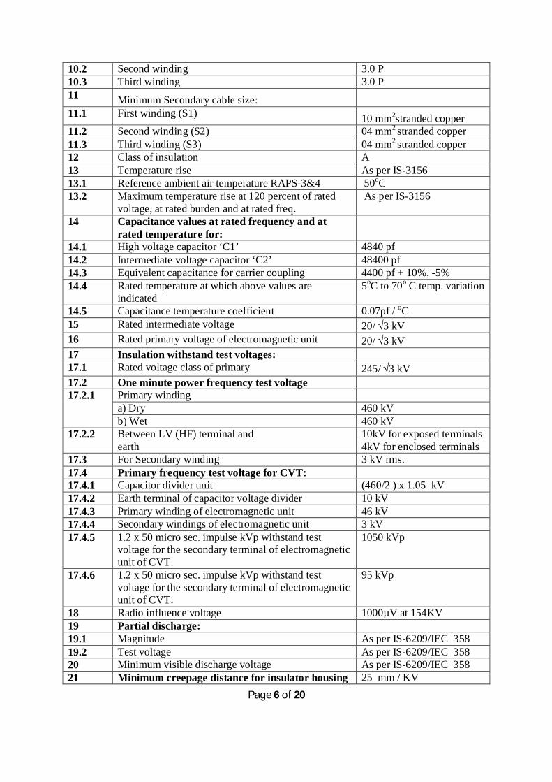
10.2 Second winding 3.0 P 10.3 Third winding 3.0 P 11 Minimum Secondary cable size: 11.1 First winding (S1) 10 mm2stranded copper 11.2 Second winding (S2) 04 mm2 stranded copper 11.3 Third winding (S3) 04 mm2 stranded copper 12 Class of insulation A 13 Temperature rise As per IS-3156 13.1 Reference ambient air temperature RAPS-3&4 50oC 13.2 Maximum temperature rise at 120 percent of rated
voltage, at rated burden and at rated freq. As per IS-3156
14 Capacitance values at rated frequency and at rated temperature for:
14.1 High voltage capacitor ‘C1’ 4840 pf 14.2 Intermediate voltage capacitor ‘C2’ 48400 pf 14.3 Equivalent capacitance for carrier coupling 4400 pf + 10%, -5% 14.4 Rated temperature at which above values are
indicated 5oC to 70o C temp. variation
14.5 Capacitance temperature coefficient 0.07pf / oC 15 Rated intermediate voltage 20/ √3 kV 16 Rated primary voltage of electromagnetic unit 20/ √3 kV 17 Insulation withstand test voltages: 17.1 Rated voltage class of primary 245/ √3 kV 17.2 One minute power frequency test voltage 17.2.1 Primary winding
a) Dry 460 kV b) Wet 460 kV
17.2.2 Between LV (HF) terminal and earth
10kV for exposed terminals 4kV for enclosed terminals
17.3 For Secondary winding 3 kV rms. 17.4 Primary frequency test voltage for CVT: 17.4.1 Capacitor divider unit (460/2 ) x 1.05 kV 17.4.2 Earth terminal of capacitor voltage divider 10 kV 17.4.3 Primary winding of electromagnetic unit 46 kV 17.4.4 Secondary windings of electromagnetic unit 3 kV 17.4.5 1.2 x 50 micro sec. impulse kVp withstand test
voltage for the secondary terminal of electromagnetic unit of CVT.
1050 kVp
17.4.6 1.2 x 50 micro sec. impulse kVp withstand test voltage for the secondary terminal of electromagnetic unit of CVT.
95 kVp
18 Radio influence voltage 1000µV at 154KV 19 Partial discharge: 19.1 Magnitude As per IS-6209/IEC 358 19.2 Test voltage As per IS-6209/IEC 358 20 Minimum visible discharge voltage As per IS-6209/IEC 358 21 Minimum creepage distance for insulator housing 25 mm / KV

Page 7 of 20
Other specifications:
i) All routine test will be carried out as per IS 3156 (Latest version and amendments). a) Verification of terminal markings b) Power frequency withstand tests on c) Capacitor Voltage divider d) Low voltage terminal of the capacitor voltage divider e) Electromagnetic unit f) Tests for accuracy. g) Partial discharge. h) Measurement of capacitance and tan delta. i) Oil leakage.
ii) Type test: Following shall constitute the type test:
j) Lightning Impulse Voltage withstand test k) HV (wet) power frequency voltage withstand test l) Temperature rise test.
m) Verification of accuracy at limits of frequency
22 Corona extinction voltage 156 kV RMS 23 Mechanical strength of voltage transformer: 23.1 Mechanical strength of voltage transformer whether
the voltage transformer is designed to withstand the various loads with factor of safety as specified in data sheet.
yes
23.2 Mechanical strength of voltage transformer provided:
23.2.1 Factor of safety 2.24 23.2.2 Bending 150 kg/cm2 24 Whether Rated voltage of earth terminal of the
voltage divider provided Yes
24.1 If yes, rated voltage 10kV 24.2 One minute power frequency withstand voltage 10 kV 25 The spark over voltage of the protective gap across
the primary side of electromagnetic unit is provided in case of CVT.
36 kV
26 Whether the series reactance/high voltage choke/ Compensating coil is provided in case of CVT.
Yes
26.1 Rating of choke for one minute power frequency test voltage
10 kV
27 Terminal box details: 27.1 Degree of protection as per IS: 2147 IP-55 28 Earthing connection Provision shall be suitable
for connecting 2 Nos. of 50 x 6 GS flat.
29 Insulating oil shall conformed IS-335 30 Provision made for accepting the change in oil
volume. N2 cushion
Page 8 of 20
n) Ferro resonance test o) Transient resonance test p) Partial Discharge test q) Mechanical tests r) Short time current
iii) Type tests on capacitor divider units:
a) Measurement of high frequency capacitance and equivalent series resistance b) Stray capacitance and stray conductance measurement on LV side c) Partial discharge d) Determination of temperature coefficient of capacitance
The manufacturer should carry out type test or submit valid test report of type test for capacitive voltage transformer being offered for supply. The type test reports should be submitted or test should be carried out at NABL accredited/ OEM test laboratory.
iv) Tentative QA plan is attached in Annexure-6. However bidder will submit detailed QA
plan for approval after PO placement and before manufacturing. v) Bidder will submit all dimensional drawings along with the offer.
Note:
1) Three nos. copies of operation, maintenance and erection manuals in Hindi / English
language shall be supplied one month prior to the dispatch of the Instrument Transformer. 2) The Bidder shall fill the response in the bidder`s response column in Annexure-2 and to be
uploaded after his authorized seal and signature. 3) The bidder shall upload the offered CVT Dimension drawing mentioning details in line with
Annexure-3. 4) The bidder shall upload the Sectional view of the 220kV CVT mentioning details in line
with Annexure-4. 5) The bidder shall upload the Insulator outdoor drawing of the 220kV CVT mentioning details
in line with Annexure-5.
D.K. Shringi
SO/E, RRS-3&4

Page 9 of 20
Annexure- 2 (CC no. 77842)
Technical Details of Capacitive Voltage Transformer:
(Bidder shall mention specifications of quoted product in the table mentioned below):
Table-1
S. No. Parameter Bidders specification for quoted item
1 Installation Indoor/Outdoor 2 Frequency 3 No. of secondary windings 4 Rated Primary voltage 5 Highest voltage 6 Rated secondary winding voltage: 6.1 First winding (S1) 6.2 Second winding (S2) 6.3 Third winding (S3) 7 Method of connection: 7.1 Primary 7.2 Secondary windings: 7.2.1 First winding (S1) 7.2.2 Second winding (S2) 7.2.3 Third winding (S3) 8 Rated voltage factor: 8.1 Continuous 8.2 Short time 9 Rated burden of secondary windings (VA): 9.1 First winding (S1) 9.2 Second winding (S2) 9.3 Third winding (S3) 9.4 Rated total thermal burden 9.5 Rated power factor of the burden 10 Accuracy class of secondaries: 10.1 First winding 10.2 Second winding 10.3 Third winding 11 Minimum Secondary cable size: 11.1 First winding (S1) S. No. Parameter Bidders specification for
quoted item 11.2 Second winding (S2) 11.3 Third winding (S3) 12 Class of insulation 13 Temperature rise

Page 10 of 20
13.1 Reference ambient air temperature RAPS-3&4 13.2 Maximum temperature rise at 120 percent of rated voltage, at
rated burden and at rated freq.
14 Capacitance values at rated frequency and at rated temperature for:
14.1 High voltage capacitor ‘C1’ 14.2 Intermediate voltage capacitor ‘C2’ 14.3 Equivalent capacitance for carrier coupling 14.4 Rated temperature at which above values are indicated 14.5 Capacitance temperature coefficient 15 Rated intermediate voltage 16 Rated primary voltage of electromagnetic unit 17 Insulation withstand test voltages: 17.1 Rated voltage class of primary 17.2 One minute power frequency test voltage 17.2.1 Primary winding
a) Dry b) Wet
17.2.2 Between LV (HF) terminal and earth
17.3 For Secondary winding 17.4 Primary frequency test voltage for CVT: 17.4.1 Capacitor divider unit 17.4.2 Earth terminal of capacitor voltage divider 17.4.3 Primary winding of electromagnetic unit 17.4.4 Secondary windings of electromagnetic unit 17.4.5 1.2 x 50 micro sec. impulse kVp withstand test voltage for the
secondary terminal of electromagnetic unit of CVT.
17.4.6 1.2 x 50 micro sec. impulse kVp withstand test voltage for the secondary terminal of electromagnetic unit of CVT.
18 Radio influence voltage 19 Partial discharge: 19.1 Magnitude 19.2 Test voltage 20 Minimum visible discharge voltage 21 Minimum creepage distance for insulator housing 22 Corona extinction voltage 23 Mechanical strength of voltage transformer: 23.1 Mechanical strength of voltage transformer whether the voltage
transformer is designed to withstand the various loads with factor of safety as specified in data sheet.
23.2 Mechanical strength of voltage transformer provided: 23.2.1 Factor of safety 23.2.2 Bending 24 Whether Rated voltage of earth terminal of the voltage divider
provided
24.1 If yes, rated voltage 24.2 One minute power frequency withstand voltage

Page 11 of 20
Bidder should mention details of Compliance of the points mentioned item sr. no. i) to v) in the Table-2 mentioned below:
Table-2
D.K. Shringi
SO/E, EMU
25 The spark over voltage of the protective gap across the primary side of electromagnetic unit is provided in case of CVT.
26 Whether the series reactance/high voltage choke/ Compensating coil is provided in case of CVT.
26.1 Rating of choke for one minute power frequency test voltage 27 Terminal box details: 27.1 Degree of protection as per IS: 2147 28 Earthing connection 29 Insulating oil shall conformed 30 Provision made for accepting the change in oil volume. 31 Is foundation of the offered CVT matching with existing CVT? 32 If not, bidder shall provide the necessary arrangement and take
approval of drawing after purchase order. Write agree/ disagree in bidders specification column.
S. No. Description of other specification Bidders compliance for specification
i) Bidder shall submit all dimensional drawings including Sectional view and Insulator of 220kV CVT, along with the offer.
ii) Tentative QA plan is attached inAnnexure-6. However bidder will submit detailed QA plan for approval after PO placement and before manufacturing.
iii) All routine test will be carried out as per IS 3156 (Latest version and amendments).
iv) Type test: Following shall constitute following type test: a) Lighting impulse Voltage withstand test b) HV (wet) power frequency voltage withstand test c) Temperature rise test d) Verification of accuracy at limits of frequency e) Ferro resonance test f) Transient resonance test g) Partial Discharge test h) Test for leakage of internal filling i) Mechanical test
The manufacturer should carry out type test or submit valid test report of type test for CVT being offered for supply. The type test reports should be witness or test should be carried out at NABL accredited/ OEM test laboratory.
v) Three nos. copies of operation, maintenance and erection manuals in Hindi / English language shall be supplied one month prior to the dispatch of the Instrument Transformer.

Page 12 of 20
Annexure - 3

Page 13 of 20
Annexure –4

Page 14 of 20
Annexure –5 (i)

Page 15 of 20
Annexure –5 (ii)


Annexure –6
QUALITY PLAN OF CAPACITIVE VOLTAGE TRANSFORMER (CVT)
1.0 QUALITY SURVEILLANCE
1.1 General
1.1.1 The general requirements regarding quality assurance, organisational set up for quality surveillance, qualification and experience details of personnel of quality Assurance department, QA Manual, Mock up test procedures etc. are covered in Section C-0 and the GCC.
2.0 Quality control plan
This indicates the requirements expected from the contractor/manufacturer of the Instrument Transformers. Subsequent to the placement of Purchase Order contractor/manufacturer shall submit” for purchaser’s approval a quality assurance plan in line with this document incorporating specific document numbers for “format of records”, “acceptance norms” and “reference documents
Abbreviations: V Verified by P Performed by W Witnessed by (After lapse of due notice to NPCIL, manufacturer may proceed with manufacture) H Hold (Unless a written clearance is obtained from NPCIL, manufacturer shall not proceed to next stage) 1 NPCIL QS 2 Prime Supplier / EPC Contractor 3 Approved External Laboratory or Sub Vendor QC (if vendor QC / facility not available.)
AD- PC Approved Document such as Tender Document, Purchase order, Drawings & Test Procedures TR- Test Report PS- Plant Standard

CHP - Customer Hold Point (Customer is NPCIL) IS - Indian Standards IEC - International Electrotechnical Commission standards IEEE - Institute of Electronics and Electrical Engineers standards
Notes:
Wherever V & W are both indicated, NPCIL QS to witness test or review TRs.
TRs not more than five year old from date of opening of Part-I of tender shall be reviewed for acceptance. Otherwise test shall be carried out.
Minor: The characteristic of a component, process or operation whose failure neither materially reduce the usability of the product in operation, nor does it affect the aesthetic aspects.
Major: The characteristic of a component, process or operation whose failure may cause operation failure which cannot be readily corrected at site or cause substandard performance, increased erection and maintenance cost, reduced life or seriously affect aesthetics or ergonomics.
Critical: The characteristics of a component, process or operation failure of which will surely cause operating failure or intermittent troubles which is difficult to rectify at site or render the unit unfit for use or safety hazards.
‘‘Failure “of a characteristic means failure to meet the ‘acceptance norms ‘. Sampling: Generally in accordance with IS: 2500. Sampling will be used as under:-
If 100% “witness” is carried out by “Prime contractor”, NPCIL will witness on sample basis, or if 100% “witness” of tests is carried out by “sub-
contractor”, “Prime contractor” will witness on sample basis.
Any deviation to this QAP shall be brought out by vendor in his offer failing which this QAP shall be complied with fully
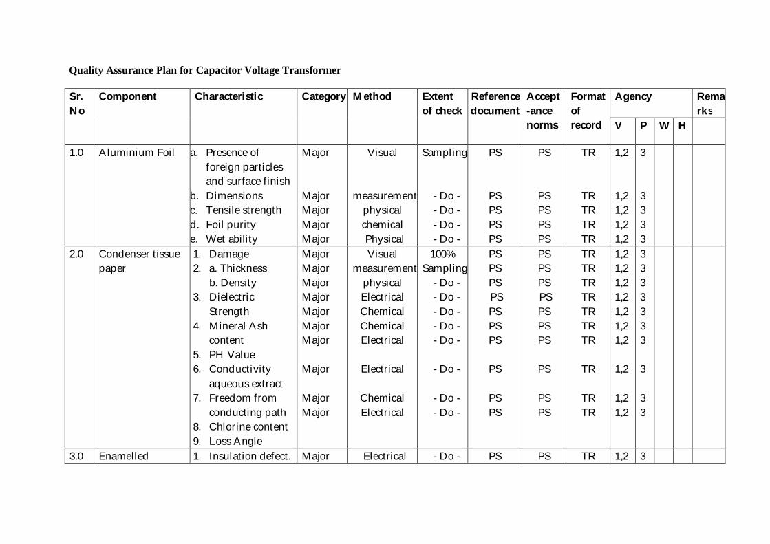
Quality Assurance Plan for Capacitor Voltage Transformer Sr.No
Component Characteristic Category Method Extent of check
Referencedocument
Accept-ance norms
Format of record
Agency Remarks
V P W H
1.0 Aluminium Foil a. Presence of foreign particles and surface finish
b. Dimensions c. Tensile strength d. Foil purity e. Wet ability
Major Major Major Major Major
Visual
measurementphysical chemical Physical
Sampling
- Do - - Do - - Do - - Do -
PS
PS PS PS PS
PS
PS PS PS PS
TR
TR TR TR TR
1,2 1,2 1,2 1,2 1,2
3 3 3 3 3
2.0 Condenser tissue paper
1. Damage 2. a. Thickness b. Density 3. Dielectric
Strength 4. Mineral Ash
content 5. PH Value 6. Conductivity
aqueous extract 7. Freedom from
conducting path 8. Chlorine content 9. Loss Angle
Major Major Major Major Major Major Major Major Major Major
Visual measurement
physical Electrical Chemical Chemical Electrical
Electrical
Chemical Electrical
100% Sampling
- Do - - Do - - Do - - Do - - Do -
- Do -
- Do - - Do -
PS PS PS PS PS PS PS
PS
PS PS
PS PS PS PS PS PS PS
PS
PS PS
TR TR TR TR TR TR TR
TR
TR TR
1,2 1,2 1,2 1,2 1,2 1,2 1,2 1,2 1,2 1,2
3 3 3 3 3 3 3 3 3 3
3.0 Enamelled 1. Insulation defect. Major Electrical - Do - PS PS TR 1,2 3

Copper wire
2. Dimensions 3. Electrical
resistance 4. Elongation 5. Jerk test 6. Resistance to
Abrasion 7. Heat shock 8. Cut Through 9. Cure test 10. Solvent test 11. Break Down
Voltage
Major Major Major Major Major Major Major Major Major
measurement Electrical
Physical Physical Physical
Physical Physical Physical Chemical Electrical
- Do - - Do -
- Do -
- Do- - Do -
- Do - - Do - - Do -
- Do - - Do -
PS PS
PS PS PS
PS PS PS PS PS
PS PS
PS PS PS
PS PS PS PS PS
TR TR
TR TR TR
TR TR TR TR TR
1,2 1,2 1,2 1,2 1,2 1,2 1,2 1,2 1,2 1,2
3 3 3 3 3 3 3 3 3 3
4.0 Core 1. Surface Defects 2. Dimension 3. Magnetic
property
Major Major Major
Visual Measurement Physical
100% SamplingSampling
PS PS PS
PS PS PS
TR TR TR
1,2 1,2 1,2
3 3 3
5.0 Porcelain
1. Dielectric strength
MAJOR HV Test 100% IS/IEC IS/IEC TR 1,2 3
2. Visual, creepage & dimension
MAJOR Measurement
100% IS/IEC IS/IEC TR 1,2 3
3. Temperature cycle
MAJOR Measurement
100% IS/IEC IS/IEC TR 1,2 3
4. Pressure Test MAJOR Measurement
100% PS PS TR 1,2 3
5. Porosity MAJOR Measurement
Sample IS/IEC IS/IEC TR 1,2 3

6. Internal flaw MAJOR Ultrasonic 100% PS PS TR 1,2 3 7. Bending strength MAJOR Mechanical Sample IS IS TR 1,2 3 8. Bending Strength
at 70 % MAJOR Mechanical 100% IS IS. TR 1,2 3
9. Parallelism & eccentricity
MAJOR Mechanical 100% IS IS. TR 1,2 3
6.0 Tank & Tank cover
1. Dimensions. 2. Leakage test 3. Fabrication 4. Galvanizing /
painting
Major Major Major Major
Measurement Physical Physical Physical
Sampling100% 100%
”
PS PS PS PS
PS PS PS PS
TR TR TR TR
1,2 1,2 1 1
3 3 3 3
2 2
7.0 H.V. Bushing 1. Surface Defects 2. Dimension 3. Dielectric tests
Major Major Major
Visual Measurement Electrical
100% ” ”
PS PS PS
PS PS PS
TR TR TR
1 1 1
3 3 3
2 2 2
8.0 Spark gap 1. Dimension 2. Breakdown
voltage
Major Major
Measurement Electrical
100% 100%
PS PS
PS PS
TR TR
1,2 1,2
3 3
9.0 Oil All characteristics as per IS:335
Major Test
Sampling
IS IS TR 1,2 3
10.0 Capacitor foil winding
1. Destructive check of foil
Major Physical -do-
PS PS TR
1,2 3
11.0 Stack pressure 1. Pressure 2. Height
Major Major
Physical measurement
100% 100%
PS PS
PS PS
TR TR
1,2 3
12.0 Drying & Impregnation
1. Control of Process
Major Physical 100% PS PS TR 1,2 3

13.0 Pressing of stack after impregnation
1. Pressure 2. Height
Major Major
Physical measurement
100% 100%
PS PS
PS PS
TR
1,2 3
14.0 Tests on complete Capacitor unit
All routine tests Natural frequency test
Major Visual/Electrical
100%
100%
IEC
PS
IEC
PS
TR
TR
3 3
1,2 1,2
1 1
15.0 Tests on Electromagnetic Unit
All routine tests Natural frequency test
Major -do- 100%
100%
IEC
PS
IEC
PS
TR
TR
3 3
1,2 1,2
1 1
16.0 Tests on complete CVT.
All routine tests All type tests Special tests
Major Critical Critical
-do- -do-
100% SamplingSampling
IEC IEC IEC
IEC IEC IEC
TR TR TR
1,2 1,2 1,2
3 3 3
1,2 1,2
1 1.
Page 20 of 20
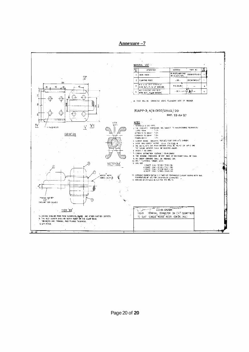
Annexure –7