annex ii technical specification iter d vh2arw v1.0...
TRANSCRIPT

Annex II
Technical Specification
- ITER_D_VH2ARW v1.0 dated 12th October 2017
for
Development of IC-Plant System Controller Prototype & Fast
controller Phase 3

Page 1 of 22
Development of IC-Plant System Controller Prototype Phase 3
Contract Technical Specifications

Page 2 of 22
Table of Contents
DEVELOPMENT OF IC-PLANT SYSTEM CONTROLLER PROTOTYPE & FAST CONTROLLER PHASE 3.........................................................................................................11 PURPOSE............................................................................................................................32 SCOPE OF WORK.............................................................................................................43 REFERENCES / TERMINOLOGY AND ACRONYMS ...............................................64 DURATION.........................................................................................................................65 RESPONSIBILITIES .........................................................................................................66 LIST OF DELIVERABLES AND DUE DATES .............................................................77 ACCEPTANCE CRITERIA..............................................................................................88 SPECIFIC REQUIREMENTS AND CONDITIONS......................................................89 WORK MONITORING / MEETING SCHEDULE .......................................................910 QUALITY ASSURANCE (QA) REQUIREMENT .........................................................911 SAFETY REQUIREMENTS...........................................................................................10

Page 3 of 22
1 PurposeIC H&CD is one of Heating and Currents Drive (H&CD) systems foreseen in ITER. The IC H&CD shall provide radio-frequency (RF) heating and current drive to the ITER plasmas in the frequency range [40 MHz to 55 MHz]. A total of 20 MW of RF power in plasma is initially required from the system. The ITER IC H&CD system is composed of two antennas in port plugs, matching systems, transmission lines, RF power sources (09), HVPS (High Voltage Power Supply) (18), plant control system (IC-PSC) and test facilities (2 RF dummy loads, port plug test facilities).
Figure 1: IC H&CD system
ICH HVPS, RF sources, TL & MS and antenna subsystems shall be procured by different procurement arrangements with different domestic agencies. HVPS, RF sources, TL & MS and antenna shall have dedicated local controllers.IC-PSC, the Plant System Controller of IC H&CD, shall control & synchronize all local controllers.
The functional architecture scheme of the IC H&CD control system consists of this main controller (IC-PSC) controlling local/subsystem Control Units. IC-PSC provides the functional/operational interface with CODAC and the Plasma Control System, while the local Control Units controls individual subsystems (HVPSs, RF Sources, TL & MS and antenna) as illustrated in Figure 2.

Page 4 of 22
Figure 2: IC H&CD I&C Functional Architecture showing Control Hierarchy
IC-PSC, shall be procured by IO. IC-PSC has preliminary design done in January 2014, which defined functional and hardware architecture as per CODAC requirement [1]. A prototype (phase 1 and 2) was developed with CODAC in order to asses these architecture feasibility. The details of the main components of the IC-PSC prototype cubicle are given in Annex 1. The details of the work performed during the previous contract are given in Annex 2 and will be discussed during the kick off meeting. The IO TRO will guide the contractor for all that concerns the ICH system and the work done during the previous phases.
2 Scope of Work
The contract main tasks are described below. The corresponding deliverables are detailed in the chapter 6.
Develop the IC PSC phase 3.
The purpose of the IC-PSC prototype located in the cubicle 20 and described in Annex 1 is to implement the functional architecture of ICH system using hardware components part of CODAC catalogue. This demonstrates that our design is compatible with CODAC core system.
On the other hand, the tools developed by CODAC team were tested and assessed. This provides essential experience of CODAC core system [1] and its subsequent evolutions.
The CODAC core system is under development process. During this phase 3 development, as for the phase 2, the contractor will have to check the updated functionalities of CODAC core system version 5.4 and if available 6.0 and propose any modifications to the existing configuration.

Page 5 of 22
The work consists mainly in programming of Field-Programmable Gate Array (FPGA) card and Siemens Programmable logic controller (PLC). Core system uses EPICS as middleware for fast controller & slow controller input/output process variable access. The EPICS IOC shall be running on Red Hat Linux OS platform.
It implies as well input/ output definitions, implementation of the corresponding variables and signals in CODAC database (SDD).
Extract of the work performed during the previous phases is given in Annex 2.
Define the hardware architecture of ICH PIS and PSS.
During this third phase, the contractor shall define the components that will be part of the Plant Safety System (PSS) and the Plant Interlock System (PIS). As for the conventional control components, the hardware will be chosen so that it satisfies the ICH safety and interlock function requirements. There are few functions associated to Health and Safety and interlocks in our system. They have been defined in the Hazard Identification Risk Assessment (HIRA) [2], the Interface sheet in between PBS51 and 46 and 48 [3 &4] and in some specific document that defined the SIL level of the functions [5].
The work consists in defining the hardware architecture of PIS and PSS, finding the corresponding component as per CODAC guideline and evaluating the cost of the PIS and PSS of ICH system.
Implement the RF signal direct sampling process in our fast controller.
The purpose of this prototype phase 3 is to go further in the development of the RF control loop by testing the RF direct sampling method.
The progress in electronics makes possible the direct acquisition of RF measurements at the frequency of the system (35 to 65 MHz). Previously a down conversion process to lower frequency was required to allow the sampling of the signals.
CODAC provides the Linux and IO driver and application support to use direct sampling cards in the ICH System :
1. IRIO_Design_Rules_for_labVIEW_for_FPGA_QQMYTY_v1_4.pdf2. IRIO_Library_user's_manual_RATM8Z_v1_2 .pdf3. NI_X-Series_EPICS_Driver_User's_Guide_3P4N3R_v1_7.pdf4. NI-RIO_EPICS_Device_Driver_User_Manual__RAJ9P8_v1_4 .pdf
This work shall be performed in close collaboration with INDA in charge of the procurement of the IC RF sources. A technical solution and the definition of which direct sampling card could be used has been proposed to INDA. We intend in IO to procure these cards and demonstrate with the corresponding implementation in our cubicle that the solution is valuable.

Page 6 of 22
Prepare the installation of the cubicle in CEA to be used in the frame of the implementation of the IO test bed
The cubicle 20 will be used in the frame of the development of the ICH test bed. For that purpose, the cubicle will have to be transferred to an external facility in CEA. The purpose of this task will be to define the component to be added to the cubicle 20 in order to be able to simulate the CODAC environment (mini CODAC) and to prepare the procedure describing the transfer process in collaboration with CODAC.
In this test bed a solid state amplifier will be installed and which will provide power up to 10 KW. With the guideline of IO TRO, the contractor will draft the control software for this component.
3 References / Terminology and Acronyms
References: [1] CODAC Core System Overview (34SDZ5 v5.4)
[2] PBS51 HIRA Final Report (Q5HT9J v1.1)
[3] 48-51 ICD
[4] 46-51 ICD
[5] O-003 Function specification for ICH RF leakage mitigation (R375P5 v1.1) (current)
Definitions are given within the text.For a complete list of ITER abbreviations see: ITER Abbreviations (ITER_D_2MU6W5).
4 DurationThe contract will have duration of 12 months
5 Responsibilities
5.1 Responsibility of ITER
ITER has the responsibility of providing detailed input data when required during the execution of the work described in Chapter 2.
Access will be granted to IDM folders to perform the tasks.
ITER shall provide offices and IT equipment at IO premises.

Page 7 of 22
5.2 Responsibility of the contractor
The contractor has the responsibility of :- regularly submitting to ITER the progress of the contract, for ITER acceptance as
per chapter 7.- implementing the IO procedures, instruction and use the corresponding templates
6 List of deliverables and due dates
The Contractor shall provide the deliverables in the form of reports. IO shall review the reports. The Contractor shall perform all the necessary modifications or iterations to the reports and submit a revised version.
Deliverables Deliverables Target Dates
D1 Develop the IC PSC phase 3:- Assess the progresses made in CODAC Core system since
January 2016 (CODAC core V 5.4)- Check the relevance of the modification as regard to the IC
PSC definition - Implement the functionality not already implemented in
the prototype.
T0+2
D2 ICH PIS:- Define the functional architecture of ICH PIS- Define the hardware architecture of the ICH PIS (List of
components)- Evaluate the associated cost
T0+4
D3 ICH PSS: - Define the functional architecture of ICH PSS- Define the hardware architecture of the ICH PSS (List of
components)- Evaluate the associated cost
T0+5
D4 IC-PSC prototype installation outside CODAC lab for ICH test bed :Draft the software associated to the Solid State power amplifier control.
T0+7
D5 IC-PSC prototype installation outside CODAC lab for ICH test bed :
- Establish the component required to add in the prototype in order to simulate the CODAC environment
- Establish the procedure to transfer the cubicle outside
T0+8

Page 8 of 22
ITER CODAC lab. D6 RF signal direct sampling:
- Assess the coding of fast controller developed in the frame of the previous contract for the RF feedback loop implementation.
- Implement and program the direct sampling cards in IC-PSC prototype. The aim is to demonstrate the possibility of direct acquisition of a 65 MHz signal. The hardware required for the test will be provided by IO.
T0+10
D7 Develop the IC PSC phase 3: - Assess the progresses made in CODAC Core system V6.0
and implement them in the prototype software
T0+12
7 Acceptance Criteria These criteria shall be the basis of acceptance by IO following the successful completion of the services.These will be in the form of monthly progress reports showing the status of the deliverables detailed in Chapter 6.
Report and Document Review criteria:Reports as deliverables shall be stored in the ITER Organization’s document management system, IDM by the Contractor for acceptance.A named ITER Organization’s Contract Technical Responsible Officer is the Approver of the delivered documents. The Approver can name one or more Reviewers(s) in the area of the report’s expertise. The Reviewer(s) can ask modifications to the report in which case the Contractor must submit a new version. The acceptance of the document by the Approver is the acceptance criterion.
8 Specific requirements and conditionsThe activities shall be driven by the IO responsible officer in the IC & LH section. The contractor’s staff will work at the IO site for the duration of the contract.
– Relevant experience in technical I&C design;– Experience in control system design, development and implementation;– Experience in fast data acquisition and real time control – Experience in Linux OS; C/C++, FPGA & PLC programming– Experience in large experimental device commissioning and operation would be an
advantage.– The contractor shall have the French Electrical Authorization in order to access
CODAC lab.
Page 9 of 22
Up to five missions per years are planned which will be reimbursed under ITER Organization conditions. Some work may be performed in CEA premises, in Cadarache IRFM labs, as the solid state power amplifier may be used for the ICH test bed.
9 Work Monitoring / Meeting ScheduleThe work will be managed by means of Monthly Progress Meetings and/or formal exchange of documents transmitted by emails which provide detailed progress. Progress Meetings will be called by the ITER Organization, to review the progress of the work, the technical problems, the requirements, the interfaces and the planning.The main purpose of the Progress Meetings is to allow the ITER Organization/IC&LH Section and the Contractor Technical Responsible Officer to:
a) Allow early detection and correction of issues that may cause delays;b) Review the completed and planned activities and assess the progress made;c) Permit fast and consensual resolution of unexpected problems;d) Clarify doubts and prevent misinterpretations of the specifications.
In addition to the Progress Meetings, if necessary, the ITER Organization and/or the Contractor may request additional meetings to address specific issues to be resolved.For all Progress Meetings, a document describing tasks done, results obtained, blocking points shall be written by the engineer.All reports will be stored in the ITER IDM in order to ensure traceability of the work performed.
10 Quality Assurance (QA) requirementThe organisation conducting these activities should have an ITER approved QA Program or an ISO 9001 accredited quality system.The general requirements are detailed in ITER Procurement Quality Requirements (ITER_D_22MFG4).Prior to commencement of the task, a Quality Plan must be submitted for IO approval giving evidence of the above and describing the organisation for this task; the skill of workers involved in the study; any anticipated sub-contractors; and giving details of who will be the independent checker of the activities (see Procurement Requirements for Producing a Quality Plan (ITER_D_22MFMW)).Documentation developed as the result of this task shall be retained by the performer of the task or the DA organization for a minimum of 5 years and then may be discarded at the direction of the IO. The use of computer software to perform a safety basis task activity such as analysis and/or modelling, etc. shall be reviewed and approved by the IO prior to its use, in accordance with Quality Assurance for ITER Safety Codes (ITER_D_258LKL)

Page 10 of 22
11 Safety requirementsITER is a Nuclear Facility identified in France by the number-INB-174 (“Installation Nucléaire de Base”).For Protection Important Components and in particular Safety Important Class components (SIC), the French Nuclear Regulation must be observed, in application of the Article 14 of the ITER Agreement.In such case the Suppliers and Subcontractors must be informed that:
- The Order 7th February 2012 applies to all the components important for the protection (PIC) and the activities important for the protection (PIA).
- The compliance with the INB-order must be demonstrated in the chain of external contractors.
- In application of article II.2.5.4 of the Order 7th February 2012, contracted activities for supervision purposes are also subject to a supervision done by the Nuclear Operator.
For the Protection Important Components, structures and systems of the nuclear facility, and Protection Important Activities the contractor shall ensure that a specific management system is implemented for his own activities and for the activities done by any Supplier and Subcontractor following the requirements of the Order 7th February 2012.

Page 11 of 22
Annex 1: List of components installed in the cubicle ICH 20
Fast Controller Hardware:
The following components are installed in the Cubicle-20 at CODAC Lab. These components were procured and purchased from the ICH PBS budget, hence dedicatedly belongs to the ICH section.Fast controller component has been integrated, interfaced and tested with the CODAC tools and applications like SDD, I&C Navigator, Maven Editor, CSS etc.
Real time RF power feedback controlled algorithm written in the frame of the development of the prototype phase 1 has been tested with these fast controllers.

Page 12 of 22
Slow Controller hardware:
Slow controller component procured by PBS51 has been integrated, interfaced and tested with the CODAC core system tools and applications like SDD, I&C Navigator, Maven Editor, CSS etc. They are part of Cubicle-20 at CODAC Lab
All the function defined in the ICH Global Architecture document for the ICMN and ICH1 Plant control system has been implemented and tested successfully with the two set of the slow controller.
Slow Controller Network
Control unit Domain Name Network Address
PLC-CPU-416-3 51CICM-PLC-0001 10.201.1.124
CP-443 51CICM-PLC-CP443-0001 10.201.1.125
PLC-CPU-416-3 51CICM-PLC-0001 10.201.1.126
CP-443 51CICM-PLC-CP443-0002 10.201.1.127
Page 13 of 22
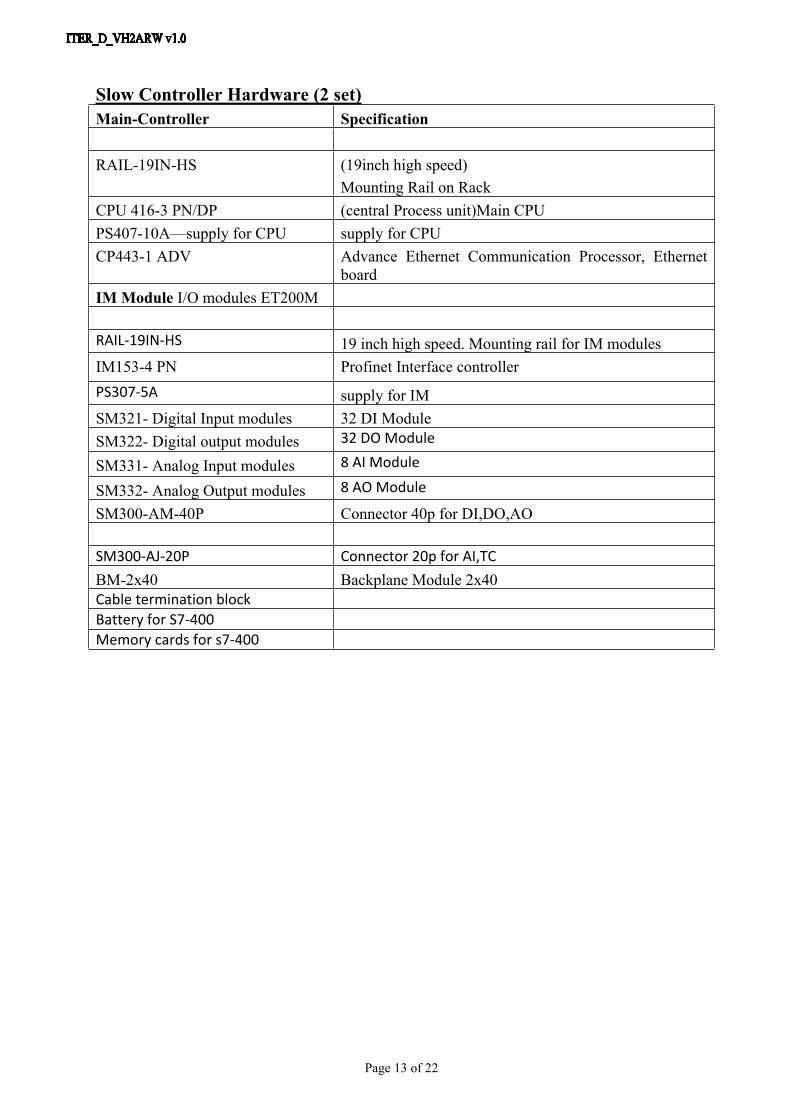
Slow Controller Hardware (2 set)Main-Controller Specification
RAIL-19IN-HS (19inch high speed)Mounting Rail on Rack
CPU 416-3 PN/DP (central Process unit)Main CPUPS407-10A—supply for CPU supply for CPU CP443-1 ADV Advance Ethernet Communication Processor, Ethernet
boardIM Module I/O modules ET200M
RAIL-19IN-HS 19 inch high speed. Mounting rail for IM modulesIM153-4 PN Profinet Interface controllerPS307-5A supply for IMSM321- Digital Input modules 32 DI ModuleSM322- Digital output modules 32 DO Module
SM331- Analog Input modules 8 AI Module
SM332- Analog Output modules 8 AO Module
SM300-AM-40P Connector 40p for DI,DO,AO
SM300-AJ-20P Connector 20p for AI,TCBM-2x40 Backplane Module 2x40Cable termination blockBattery for S7-400Memory cards for s7-400

Page 14 of 22
Annex 2: Extract of the development made in the prototype PLC and fast controllers

Page 15 of 22

Page 16 of 22

Page 17 of 22

Page 18 of 22

Page 19 of 22

Page 20 of 22

Page 21 of 22

Page 22 of 22