annex 4 supplementary guidelines on good manufacturing ... · pdf filesupplementary guidelines...
TRANSCRIPT

107
© World Health OrganizationWHO Technical Report Series, No. 937, 2006
Annex 4Supplementary guidelines on good manufacturing practices: validation
1. Introduction 2. Scope 3. Glossary 4. Relationship between validation and qualifi cation 5. Validation 5.1. Approaches to validation 5.2. Scope of validation 6. Qualifi cation 7. Calibration and verifi cation 8. Validation master plan 9. Qualifi cation and validation protocols 10. Qualifi cation and validation reports 11. Qualifi cation stages 12. Change control 13. Personnel
References
Appendix 1Validation of heating, ventilation and air-conditioning systems
Appendix 2Validation of water systems for pharmaceutical use
Appendix 3
Cleaning validation
Appendix 4Analytical method validation
Appendix 5Validation of computerized systems
Appendix 6Qualifi cation of systems and equipment
Appendix 7Non-sterile process validation
TSR2006_Annexs1_5.indd 107TSR2006_Annexs1_5.indd 107 4.5.2006 16:12:534.5.2006 16:12:53

108
1. IntroductionValidation is an essential part of good manufacturing practices (GMP). It is, therefore, an element of the quality assurance programme associated with a particular product or process. The basic principles of quality assurance have as their goal the production of products that are fi t for their intended use. These principles are as follows:
• Quality, safety and effi cacy must be designed and built into the product.• Quality cannot be inspected or tested into the product.• Each critical step of the manufacturing process must be validated. Other
steps in the process must be under control to maximize the probability that the fi nished product consistently and predictably meets all quality and design specifi cations.
Validation of processes and systems is fundamental to achieving these goals. It is by design and validation that a manufacturer can establish confi dence that the manufactured products will consistently meet their product specifi cations.
Documentation associated with validation includes:
— standard operating procedures (SOPs)— specifi cations— validation master plan (VMP)— qualifi cation protocols and reports— validation protocols and reports.
The implementation of validation work requires considerable resources such as:
• Time: generally validation work is subject to rigorous time schedules.• Financial: validation often requires the time of specialized personnel and
expensive technology.• Human: validation requires the collaboration of experts from various dis-
ciplines (e.g. a multidisciplinary team, comprising quality assurance, en-gineering, manufacturing and other disciplines, depending on the product and process to be validated).
These guidelines aim to give guidance to inspectors of pharmaceutical manu-facturing facilities and manufacturers of pharmaceutical products on the requirements for validation. The main part covers the general principles of validation and qualifi cation. In addition to the main part, appendices on vali-dation and qualifi cation (e.g. cleaning, computer and computerized systems, equipment, utilities and systems, and analytical methods) are included.
2. Scope2.1 These guidelines focus mainly on the overall concept of validation and are intended as a basic guide for use by GMP inspectors and manufac-
TSR2006_Annexs1_5.indd 108TSR2006_Annexs1_5.indd 108 4.5.2006 16:12:534.5.2006 16:12:53

109
turers. It is not the intention to be prescriptive in specifi c validation require-ments. This document serves as general guidance only, and the principles may be considered useful in its application in the manufacture and control of active pharmaceutical ingredients (APIs) and fi nished pharmaceutical products. Validation of specifi c processes and products, for example in ster-ile product manufacture, requires much more consideration and a detailed approach that is beyond the scope of this document.
2.2 There are many factors affecting the different types of validation and it is, therefore, not intended to defi ne and address all aspects related to one particular type of validation here.
2.3 Manufacturers should plan validation in a manner that will ensure regulatory compliance and ensuring that product quality, safety and consis-tency are not compromised.
2.4 The general text in the main part of these guidelines may be appli-cable to validation and qualifi cation of premises, equipment, utilities and systems, and processes and procedures. More specifi c principles of quali-fi cation and validation are addressed in the appendices. Semi-automatic or fully automatic clean-in-place (CIP) systems and other special cases should be treated separately.
3. GlossaryThe defi nitions given below apply to the terms used in these guidelines. They may have different meanings in other contexts.
calibration
The set of operations that establish, under specifi ed conditions, the relation-ship between values indicated by an instrument or system for measuring (for example, weight, temperature and pH), recording, and controlling, or the values represented by a material measure, and the corresponding known values of a reference standard. Limits for acceptance of the results of mea-suring should be established.
computer validation
Documented evidence which provides a high degree of assurance that a computerized system analyses, controls and records data correctly and that data processing complies with predetermined specifi cations.
commissioning
The setting up, adjustment and testing of equipment or a system to ensure that it meets all the requirements, as specifi ed in the user requirement speci-fi cation, and capacities as specifi ed by the designer or developer. Commis-sioning is carried out before qualifi cation and validation.
TSR2006_Annexs1_5.indd 109TSR2006_Annexs1_5.indd 109 4.5.2006 16:12:534.5.2006 16:12:53

110
concurrent validation
Validation carried out during routine production of products intended for sale.
cleaning validation
Documented evidence to establish that cleaning procedures are remov-ing residues to predetermined levels of acceptability, taking into con-sideration factors such as batch size, dosing, toxicology and equipment size.
design qualifi cation (DQ)
Documented evidence that the premises, supporting systems, utilities, equipment and processes have been designed in accordance with the re-quirements of GMP.
good engineering practices (GEP)
Established engineering methods and standards that are applied throughout the project life-cycle to deliver appropriate, cost-effective solutions.
installation qualifi cation (IQ)
The performance of tests to ensure that the installations (such as machines, measuring devices, utilities and manufacturing areas) used in a manufactur-ing process are appropriately selected and correctly installed and operate in accordance with established specifi cations.
operational qualifi cation (OQ)
Documented verifi cation that the system or subsystem performs as intended over all anticipated operating ranges.
performance qualifi cation (PQ)
Documented verifi cation that the equipment or system operates consistently and gives reproducibility within defi ned specifi cations and parameters for prolonged periods. (In the context of systems, the term “process validation” may also be used.)
process validation
Documented evidence which provides a high degree of assurance that a specifi c process will consistently result in a product that meets its predeter-mined specifi cations and quality characteristics.
prospective validation
Validation carried out during the development stage on the basis of a risk analysis of the production process, which is broken down into individual steps; these are then evaluated on the basis of past experience to determine whether they may lead to critical situations.
TSR2006_Annexs1_5.indd 110TSR2006_Annexs1_5.indd 110 4.5.2006 16:12:534.5.2006 16:12:53

111
qualifi cation
Action of proving and documenting that any premises, systems and equip-ment are properly installed, and/or work correctly and lead to the expected results. Qualifi cation is often a part (the initial stage) of validation, but the individual qualifi cation steps alone do not constitute process validation.
retrospective validation
Involves the evaluation of past experience of production on the condition that composition, procedures, and equipment remain unchanged.
revalidation
Repeated validation of an approved process (or a part thereof) to ensure continued compliance with established requirements.
standard operating procedure (SOP)
An authorized written procedure giving instructions for performing opera-tions not necessarily specifi c to a given product or material but of a more general nature (e.g. equipment operation, maintenance and cleaning; vali-dation; cleaning of premises and environmental control; sampling and in-spection). Certain SOPs may be used to supplement product-specifi c master batch production documentation.
validation
Action of proving and documenting that any process, procedure or method actually and consistently leads to the expected results.
validation protocol (or plan) (VP)
A document describing the activities to be performed in a validation, in-cluding the acceptance criteria for the approval of a manufacturing process — or a part thereof — for routine use.
validation report (VR)
A document in which the records, results and evaluation of a completed validation programme are assembled and summarized. It may also contain proposals for the improvement of processes and/or equipment.
validation master plan (VMP)
The VMP is a high-level document that establishes an umbrella validation plan for the entire project and summarizes the manufacturer’s overall phi-losophy and approach, to be used for establishing performance adequacy. It provides information on the manufacturer’s validation work programme and defi nes details of and timescales for the validation work to be performed, including a statement of the responsibilities of those implementing the plan.
TSR2006_Annexs1_5.indd 111TSR2006_Annexs1_5.indd 111 4.5.2006 16:12:534.5.2006 16:12:53

112
verifi cation
The application of methods, procedures, tests and other evaluations, in ad-dition to monitoring, to determine compliance with the GMP principles.
worst case
A condition or set of conditions encompassing the upper and lower processing limits for operating parameters and circumstances, within SOPs, which pose the greatest chance of product or process failure when compared to ideal con-ditions. Such conditions do not necessarily include product or process failure.
4. Relationship between validation and qualifi cationValidation and qualifi cation are essentially components of the same concept. The term qualifi cation is normally used for equipment, utilities and systems, and validation for processes. In this sense, qualifi cation is part of validation.
5. Validation5.1 Approaches to validation
5.1.1 There are two basic approaches to validation — one based on evi-dence obtained through testing (prospective and concurrent validation), and one based on the analysis of accumulated (historical) data (retrospective validation). Whenever possible, prospective validation is preferred. Retro-spective validation is no longer encouraged and is, in any case, not appli-cable to the manufacturing of sterile products.
5.1.2 Both prospective and concurrent validation, may include:
• extensive product testing, which may involve extensive sample testing (with the estimation of confi dence limits for individual results) and the demonstration of intra- and inter-batch homogeneity;
• simulation process trials;• challenge/worst case tests, which determine the robustness of the pro-
cess; and• control of process parameters being monitored during normal production
runs to obtain additional information on the reliability of the process.
5.2 Scope of validation
5.2.1 There should be an appropriate and suffi cient system including orga-nizational structure and documentation infrastructure, suffi cient personnel and fi nancial resources to perform validation tasks in a timely manner. Man-agement and persons responsible for quality assurance should be involved.
5.2.2 Personnel with appropriate qualifi cations and experience should be responsible for performing validation. They should represent different departments depending on the validation work to be performed.
TSR2006_Annexs1_5.indd 112TSR2006_Annexs1_5.indd 112 4.5.2006 16:12:544.5.2006 16:12:54

113
5.2.3 There should be proper preparation and planning before validation is performed. There should be a specifi c programme for validation activities.
5.2.4 Validation should be performed in a structured way according to the documented procedures and protocols.
5.2.5 Validation should be performed:
— for new premises, equipment, utilities and systems, and processes and procedures;
— at periodic intervals; and— when major changes have been made.
(Periodic revalidation or periodic requalifi cation may be substituted, where appropriate, with periodic evaluation of data and information to establish whether requalifi cation or revalidation is required.)
5.2.6 Validation should be performed in accordance with written protocols. A written report on the outcome of the validation should be produced.
5.2.7 Validation should be done over a period of time, e.g. at least three consecutive batches (full production scale) should be validated, to demon-strate consistency. Worst case situations should be considered.
5.2.8 There should be a clear distinction between in-process controls and validation. In-process tests are performed during the manufacture of each batch according to specifi cations and methods devised during the develop-ment phase. Their objective is to monitor the process continuously.
5.2.9 When a new manufacturing formula or method is adopted, steps should be taken to demonstrate its suitability for routine processing. The defi ned process, using the materials and equipment specifi ed, should be shown to result in the consistent yield of a product of the required quality.
5.2.10 Manufacturers should identify what validation work is needed to prove that critical aspects of their operations are appropriately controlled. Signifi cant changes to the facilities or the equipment, and processes that may affect the quality of the product should be validated. A risk assessment approach should be used to determine the scope and extent of validation required.
6. Qualifi cation6.1 Qualifi cation should be completed before process validation is per-formed. The process of qualifi cation should be a logical, systematic process and should start from the design phase of the premises, equipment, utilities and equipment.
TSR2006_Annexs1_5.indd 113TSR2006_Annexs1_5.indd 113 4.5.2006 16:12:544.5.2006 16:12:54

114
6.2 Depending on the function and operation of the equipment, utility or system, only installation qualifi cation (IQ) and operational qualifi cation (OQ) may be required, as the correct operation of the equipment, utility or system could be considered to be a suffi cient indicator of its performance (refer to Section 11 for IQ, OQ and performance qualifi cation (PQ)). (The equipment, utility and system should then be maintained, monitored and calibrated according to a regular schedule.)
6.3 Major equipment and critical utilities and systems, however, require IQ, OQ and PQ.
7. Calibration and verifi cation7.1 Calibration and verifi cation of equipment, instruments and other devices, as applicable, used in production and quality control, should be performed at regular intervals.
7.2 Personnel who carry out calibration and preventive maintenance should have appropriate qualifi cations and training.
7.3 A calibration programme should be available and should provide infor-mation such as calibration standards and limits, responsible persons, calibra-tion intervals, records and actions to be taken when problems are identifi ed.
7.4 There should be traceability to standards (e.g. national, regional or international standards) used in the calibration.
7.5 Calibrated equipment, instruments and other devices should be la-belled, coded or otherwise identifi ed to indicate the status of calibration and the date on which recalibration is due.
7.6 When the equipment, instruments and other devices have not been used for a certain period of time, their function and calibration status should be verifi ed and shown to be satisfactory before use.
8. Validation master planThe validation master plan (VMP) should refl ect the key elements of the validation programme. It should be concise and clear and contain at least the following:
— a validation policy— organizational structure of validation activities— summary of facilities, systems, equipment and processes validated and
to be validated— documentation format (e.g. protocol and report format)— planning and scheduling
TSR2006_Annexs1_5.indd 114TSR2006_Annexs1_5.indd 114 4.5.2006 16:12:544.5.2006 16:12:54

115
— change control— references to existing documents.
9. Qualifi cation and validation protocols9.1 There should be qualifi cation and validation protocols describing the qualifi cation and validation study to be performed.
9.2 As a minimum the protocols should include the following signifi cant background information:
— the objectives of the study— the site of the study— the responsible personnel— description of SOPs to be followed— equipment to be used; standards and criteria for the relevant products
and processes— the type of validation— the processes and/or parameters— sampling, testing and monitoring requirements— predetermined acceptance criteria for drawing conclusions.
9.3 There should be a description of the way in which the results will be analysed.
9.4 The protocol should be approved prior to use. Any changes to a pro-tocol should be approved prior to implementation of the change.
10. Qualifi cation and validation reports10.1 There should be written reports on the qualifi cation and validation performed.
10.2 Reports should refl ect the protocols followed and include at least the title and objective of the study; reference to the protocol; details of material, equipment, programmes and cycles used; procedures and test methods.
10.3 The results should be evaluated, analysed and compared against the pre-determined acceptance criteria. The results should meet the acceptance criteria; deviations and out-of-limit results should be investigated. If these deviations are accepted, this should be justifi ed. Where necessary further studies should be performed.
10.4 The departments responsible for the qualifi cation and validation work should approve the completed report.
10.5 The conclusion of the report should state whether or not the outcome of the qualifi cation and/or validation was considered successful.
TSR2006_Annexs1_5.indd 115TSR2006_Annexs1_5.indd 115 4.5.2006 16:12:544.5.2006 16:12:54

116
10.6 The quality assurance department should approve the report after the fi nal review. The criteria for approval should be in accordance with the company’s quality assurance system.
10.7 Any deviations found during the validation process should be acted upon and documented as such. Corrective actions may be required.
11. Qualifi cation stages11.1 There are four stages of qualifi cation:
— design qualifi cation (DQ);— installation qualifi cation (IQ);— operational qualifi cation (OQ); and— performance qualifi cation (PQ).
11.2 All SOPs for operation, maintenance and calibration should be prepared during qualifi cation.
11.3. Training should be provided to operators and training records should be maintained.
Design qualifi cation
11.4 Design qualifi cation should provide documented evidence that the design specifi cations were met.
Installation qualifi cation
11.5 Installation qualifi cation should provide documented evidence that the installation was complete and satisfactory.
11.6 The purchase specifi cations, drawings, manuals, spare parts lists and vendor details should be verifi ed during installation qualifi cation.
11.7 Control and measuring devices should be calibrated.
Operational qualifi cation
11.8 Operational qualifi cation should provide documented evidence that utilities, systems or equipment and all its components operate in accor-dance with operational specifi cations.
11.9 Tests should be designed to demonstrate satisfactory operation over the normal operating range as well as at the limits of its operating condi-tions (including worst case conditions).
11.10 Operation controls, alarms, switches, displays and other operational components should be tested.
TSR2006_Annexs1_5.indd 116TSR2006_Annexs1_5.indd 116 4.5.2006 16:12:544.5.2006 16:12:54

117
11.11 Measurements made in accordance with a statistical approach should be fully described.
Performance qualifi cation
11.12 Performance qualifi cation should provide documented evidence that utilities, systems or equipment and all its components can consistently per-form in accordance with the specifi cations under routine use.
11.13 Test results should be collected over a suitable period of time to prove consistency.
Requalifi cation
11.14 Requalifi cation should be done in accordance with a defi ned schedule. The frequency of requalifi cation may be determined on the basis of factors such as the analysis of results relating to calibration, verifi cation and maintenance.
11.15 There should be periodic requalifi cation, as well as requalifi cation after changes (such as changes to utilities, systems, equipment; maintenance work; and movement). (See also point 5.2.5 above and section 12 below.)
11.16 Requalifi cation should be considered as part of the change control procedure.
Revalidation
11.17 Processes and procedures should be revalidated to ensure that they remain capable of achieving the intended results.
11.18 There should be periodic revalidation, as well as revalidation after changes. (See also points 5.2.5 above, point 11.21 below and section 12 below.)
11.19 Revalidation should be done in accordance with a defi ned schedule.
11.20 The frequency and extent of revalidation should be determined using a risk-based approach together with a review of historical data.
Periodic revalidation
11.21 Periodic revalidation should be performed to assess process changes that may occur gradually over a period of time, or because of wear of equipment.
11.22 The following should be considered when periodic revalidation is performed:
— master formulae and specifi cations;— SOPs;— records (e.g. of calibration, maintenance and cleaning); and— analytical methods.
TSR2006_Annexs1_5.indd 117TSR2006_Annexs1_5.indd 117 4.5.2006 16:12:544.5.2006 16:12:54

118
Revalidation after change
11.23 Revalidation should be performed following a change that could have an effect on the process, procedure, quality of the product and/or the product characteristics. Revalidation should be considered as part of the change control procedure.
11.24 The extent of revalidation will depend on the nature and signifi cance of the change(s).
11.25 Changes should not adversely affect product quality or process characteristics.
11.26 Changes requiring revalidation should be defi ned in the validation plan and may include:
• changes in starting materials (including physical properties, such as density, viscosity or particle size distribution that may affect the process or product);
• change of starting material manufacturer;• transfer of processes to a different site (including change of facilities and
installations which infl uence the process);• changes of primary packaging material (e.g. substituting plastic for glass);• changes in the manufacturing process (e.g. mixing times or drying tem-
peratures);• changes in the equipment (e.g. addition of automatic detection systems,
installation of new equipment, major revisions to machinery or apparatus and breakdowns);
• production area and support system changes (e.g. rearrangement of areas, or a new water treatment method);
• appearance of negative quality trends;• appearance of new fi ndings based on current knowledge, e.g. new tech-
nology;• support system changes.
Changes of equipment which involve the replacement of equipment on a “like-for-like” basis would not normally require a revalidation. For exam-ple, installation of a new centrifugal pump to replace an older model would not necessarily require revalidation.
12. Change control12.1 Changes should be controlled in accordance with a SOP as changes may have an impact on a qualifi ed utility, system or piece of equipment, and a validated process and/or procedure.
12.2 The procedure should describe the actions to be taken, including the need for and extent of qualifi cation or validation to be done.
TSR2006_Annexs1_5.indd 118TSR2006_Annexs1_5.indd 118 4.5.2006 16:12:544.5.2006 16:12:54

119
12.3 Changes should be formally requested, documented and approved before implementation. Records should be maintained.
13. Personnel13.1 Personnel should demonstrate that they are appropriately qualifi ed, where relevant.
13.2 Personnel requiring qualifi cation include, for example:
— laboratory analysts;— personnel following critical procedures;— personnel doing data entry in computerized systems; and— risk assessors.
TSR2006_Annexs1_5.indd 119TSR2006_Annexs1_5.indd 119 4.5.2006 16:12:554.5.2006 16:12:55

120
Appendix 1Validation of heating, ventilation and air-conditioning systems
1. General2. Commissioning3. Qualifi cation4. Reference
1. General1.1 The heating, ventilation and air-conditioning (HVAC) system plays an important role in the protection of the product, the personnel and the environment.
1.2 For all HVAC installation components, subsystems or parameters, critical parameters and non-critical parameters should be determined.
1.3 Some of the parameters of a typical HVAC system that should be qualifi ed include:
— room temperature and humidity;— supply air and return air quantities;— room pressure, air change rate, fl ow patterns, particle count and clean-
up rates; and— unidirectional fl ow velocities and HEPA fi lter penetration tests.
2. Commissioning2.1 Commissioning should involve the setting up, balancing, adjustment and testing of the entire HVAC system, to ensure that the system meets all the requirements, as specifi ed in the user requirement specifi cation, and capacities as specifi ed by the designer or developer.
2.2 The installation records of the system should provide documented evidence of all measured capacities of the system.
2.3 The data should include items such as the design and measured fi gures for airfl ows, water fl ows, system pressures and electrical amperages.These should be contained in the operating and maintenance manuals(O & M manuals).
2.4 Acceptable tolerances for all system parameters should be specifi ed prior to commencing the physical installation.
2.5 Training should be provided to personnel after installation of the system, and should include how to perform operation and maintenance.
TSR2006_Annexs1_5.indd 120TSR2006_Annexs1_5.indd 120 4.5.2006 16:12:554.5.2006 16:12:55
121
2.6 O & M manuals, schematic drawings, protocols and reports should be maintained as reference documents for any future changes and upgrades to the system.
2.7 Commissioning should be a precursor to system qualifi cation and validation.
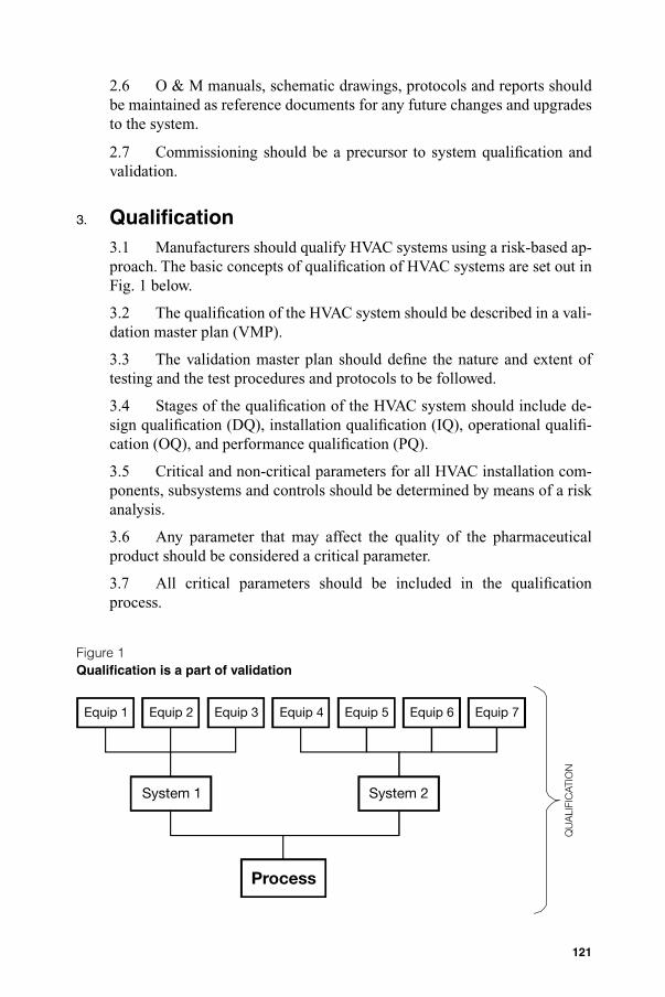
3. Qualifi cation3.1 Manufacturers should qualify HVAC systems using a risk-based ap-proach. The basic concepts of qualifi cation of HVAC systems are set out in Fig. 1 below.
3.2 The qualifi cation of the HVAC system should be described in a vali-dation master plan (VMP).
3.3 The validation master plan should defi ne the nature and extent of testing and the test procedures and protocols to be followed.
3.4 Stages of the qualifi cation of the HVAC system should include de-sign qualifi cation (DQ), installation qualifi cation (IQ), operational qualifi -cation (OQ), and performance qualifi cation (PQ).
3.5 Critical and non-critical parameters for all HVAC installation com-ponents, subsystems and controls should be determined by means of a risk analysis.
3.6 Any parameter that may affect the quality of the pharmaceutical product should be considered a critical parameter.
3.7 All critical parameters should be included in the qualifi cation process.
Figure 1Qualifi cation is a part of validation
Equip 1 Equip 2 Equip 3 Equip 4 Equip 5 Equip 6
QU
ALI
FIC
ATIO
N
Equip 7
System 2System 1
Process
TSR2006_Annexs1_5.indd 121TSR2006_Annexs1_5.indd 121 4.5.2006 16:12:554.5.2006 16:12:55

122
Note: A realistic approach to differentiating between critical and non-critical parameters is required, to avoid making the validation process unnecessarily complex.Example:• The humidity of the room where the product is exposed should be
considered a critical parameter when a humidity-sensitive product is being manufactured. The humidity sensors and the humidity monitoring system should, therefore, be qualifi ed. The heat transfer system, chemi-cal drier or steam humidifi er, which is producing the humidity-controlled air, is further removed from the product and may not require operational qualifi cation.
• A room cleanliness classifi cation is a critical parameter and, therefore, the room air-change rates and high-effi ciency particulate air (HEPA) fi lters should be critical parameters and require qualifi cation. Items such as the fan generating the airfl ow and the primary and second-ary fi lters are non-critical parameters, and may not require operational qualifi cation.
3.8 Non-critical systems and components should be subject to good engineering practice (GEP) and may not necessarily require full qualifi cation.
3.9 A change control procedure should be followed when changes are planned to the HVAC system, its components, and controls, that may affect critical parameters.
3.10 Acceptance criteria and limits should be defi ned during the design stage.
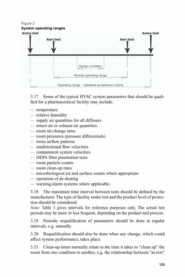
3.11 The manufacturer should defi ne design conditions, normal operat-ing ranges, operating ranges, and alert and action limits.
3.12 Design condition and normal operating ranges should be identifi ed and set to realistically achievable parameters.
3.13 All parameters should fall within the design condition range during system operational qualifi cation. Conditions may go out of the design condition range during normal operating procedures but they should remain within the operating range.
3.14 Out-of-limit results (e.g. action limit deviations) should be recorded and form part of the batch manufacturing records.
3.15 The relationships between design conditions, operating range and qualifi ed acceptance criteria are given in Figure 2.
3.16 A narrow range of relative humidities coupled with a wide range of temperatures is unacceptable as changes in temperature will automatically give rise to variations in the relative humidity.
TSR2006_Annexs1_5.indd 122TSR2006_Annexs1_5.indd 122 4.5.2006 16:12:554.5.2006 16:12:55
123
3.17 Some of the typical HVAC system parameters that should be quali-fi ed for a pharmaceutical facility may include:
— temperature— relative humidity— supply air quantities for all diffusers— return air or exhaust air quantities— room air-change rates— room pressures (pressure differentials)— room airfl ow patterns— unidirectional fl ow velocities— containment system velocities— HEPA fi lter penetration tests— room particle counts— room clean-up rates— microbiological air and surface counts where appropriate— operation of de-dusting— warning/alarm systems where applicable.
3.18 The maximum time interval between tests should be defi ned by the manufacturer. The type of facility under test and the product level of protec-tion should be considered.Note: Table 1 gives intervals for reference purposes only. The actual testperiods may be more or less frequent, depending on the product and process.
3.19 Periodic requalifi cation of parameters should be done at regular intervals, e.g. annually.
3.20 Requalifi cation should also be done when any change, which could affect system performance, takes place.
3.21 Clean-up times normally relate to the time it takes to “clean up” the room from one condition to another, e.g. the relationship between “at-rest”
Figure 2System operating rangesAction limit
Alert limit Alert limit
Action limit
Design condition
Normal operating range
Operating range – validated acceptance criteria
TSR2006_Annexs1_5.indd 123TSR2006_Annexs1_5.indd 123 4.5.2006 16:12:554.5.2006 16:12:55

124
and “operational” conditions in the clean area may be used as the criteria for clean-up tests. Therefore, the clean-up time can be expressed as the time taken to change from an “operational” condition to an “at-rest” condition.
4. Reference1. Supplementary guidelines on good manufacturing practices for heating,
ventilation and air-conditioning systems for non-sterile pharmaceutical dosage forms. WHO Expert Committee on Specifi cations for Pharmaceutical Preparations. Fortieth report. Geneva, World Health Organization, 2006(WHO Technical Report Series, No. 937), Annex 2.
Table 1.Strategic tests (for reference purposes only)
Schedule of tests to demonstrate continuing compliance
Test parameter Clean area class
Max. time interval
Test procedure
Particle count test(verifi cation of cleanliness)
All classes 6 months Dust particle counts to be carried out and printouts of results pro-duced.No. of readings and positions of tests to be in accordance with ISO 14644-1 Annex B
Air pressure difference(To verify absence of cross-contamination)
All classes 12 months Log of pressure differential readings to be produced or critical plants should be logged daily, preferably continuously. A 15 Pa pressure dif-ferential between different zones is recommended. In accordance with ISO 14644-3 Annex B5
Airfl ow volume(To verify air change rates)
All classes 12 months Airfl ow readings for supply air and return air grilles to be measured and air change rates to be calculated. In accordance with ISO 14644-3 Annex B13
Airfl ow velocity(To verify unidirectional fl ow or containment conditions)
All classes 12 months Air velocities for containment systems and unidirectional fl ow protection systems to be measured. In accordance with ISO 14644-3 Annex B4
Source: ISO 14644 Standard, given for reference purposes only.
TSR2006_Annexs1_5.indd 124TSR2006_Annexs1_5.indd 124 4.5.2006 16:12:564.5.2006 16:12:56

125
Appendix 2Validation of water systems for pharmaceutical use
1. General2. Start-up and commissioning of water systems3. Qualifi cation4. Reference
1. General1.1 All water-treatment systems should be subject to planned mainte-nance, validation and monitoring.
1.2 Validation of water systems should consist of at least three phases: Phase 1: investigational phase; Phase 2: short-term control; and Phase 3: long-term control.
1.3 During the period following phase 3 (typically running for one year) the objective should be to demonstrate that the system is under control over a long period of time. Sampling may be reduced from, e.g. daily to weekly.
1.4 The validation performed and revalidation requirements should be included in the “Water quality manual”.
2. Start-up and commissioning of water systems2.1 Planned, well-defi ned, successful and well-documented commission-ing is an essential precursor to successful validation of water systems. The commissioning work should include setting to work, system set-up, controls, loop tuning and recording of all system performance parameters. If it is in-tended to use or refer to commissioning data within the validation work then the quality of the commissioning work and associated data and documenta-tion must be commensurate with the validation plan requirements.
3. Qualifi cation3.1 Water for pharmaceutical use (WPU), purifi ed water (PW), highly purifi ed water (HPW) and water for injections (WFI) systems are all con-sidered to be direct impact, quality critical systems that should be qualifi ed. The qualifi cation should follow the validation convention of design review or design qualifi cation (DQ), installation qualifi cation (IQ), operational qualifi cation (OQ) and performance qualifi cation (PQ).
3.2 This guidance does not defi ne the standard requirements for the con-ventional validation stages DQ, IQ and OQ, but concentrates on the par-ticular PQ approach that should be used for WPU systems to demonstrate
TSR2006_Annexs1_5.indd 125TSR2006_Annexs1_5.indd 125 4.5.2006 16:12:564.5.2006 16:12:56
126
their consistent and reliable performance. A three-phase approach should be used to satisfy the objective of proving the reliability and robustness of the system in service over an extended period.
Phase 1. A test period of 2–4 weeks should be spent monitoring the sys-tem intensively. During this period the system should operate continuously without failure or performance deviation. The following procedures should be included in the testing approach.
• Undertake chemical and microbiological testing in accordance with a defi ned plan.
• Sample the incoming feed-water to verify its quality.• Sample after each step in the purifi cation process daily.• Sample at each point of use and at other defi ned sampling points daily.• Develop appropriate operating ranges.• Develop and fi nalize operating, cleaning, sanitizing and maintenance
procedures.• Demonstrate production and delivery of product water of the required
quality and quantity.• Use and refi ne the standard operating procedures (SOPs) for operation,
maintenance, sanitization and troubleshooting.• Verify provisional alert and action levels.• Develop and refi ne the test-failure procedure.
Phase 2. A further test period of 2–4 weeks should be spent carrying out further intensive monitoring while deploying all the refi ned SOPs after the satisfactory completion of phase 1. The sampling scheme should be gener-ally the same as in phase 1. Water can be used for manufacturing purposes during this phase. The approach should also:
— demonstrate consistent operation within established ranges; and— demonstrate consistent production and delivery of water of the required quan-
tity and quality when the system is operated in accordance with the SOPs.
Phase 3. Phase 3 typically runs for one year after the satisfactory comple-tion of phase 2. Water can be used for manufacturing purposes during this phase which has the following objectives and features:
• Demonstrate extended reliable performance.• Ensure that seasonal variations are evaluated.• The sample locations, sampling frequencies and tests should be reduced
to the normal routine pattern based on established procedures proven dur-ing phases 1 and 2.
Reference1. WHO good manufacturing practices: water for pharmaceutical use. Geneva, World
Health Organization 2005 (WHO Technical Report Series, No. 929), Annex 3.
TSR2006_Annexs1_5.indd 126TSR2006_Annexs1_5.indd 126 4.5.2006 16:12:564.5.2006 16:12:56

127
Appendix 3Cleaning validation
1. Principle2. Scope3. General4. Cleaning validation protocols and reports 4.1 Cleaning validation protocols 4.2 Cleaning validation reports5. Personnel6. Equipment7. Detergents8. Microbiology9. Sampling
9.1 General 9.2 Direct surface sampling (direct method) 9.3 Rinse samples (indirect method) 9.4 Batch placebo method 10. Analytical methods
11. Establishing acceptable limits
1. Principle1.1 The objectives of good manufacturing practices (GMP) include the prevention of possible contamination and cross-contamination of pharma-ceutical starting materials and products.
1.2 Pharmaceutical products can be contaminated by a variety of substances such as contaminants associated with microbes, previous products (both active pharmaceutical ingredients (API) and excipient residues), residues of cleaning agents, airborne materials, such as dust and particulate matter, lubricants and ancillary material, such as disinfectants, and decomposition residues from:
— product residue breakdown occasioned by, e.g. the use of strong acids and alkalis during the cleaning process; and
— breakdown products of the detergents, acids and alkalis that may be used as part of the cleaning process.
1.3 Adequate cleaning procedures play an important role in preventing contamination and cross-contamination. Validation of cleaning methods provides documented evidence that an approved cleaning procedure will provide clean equipment, suitable for its intended use.
1.4 The objective of cleaning validation is to prove that the equipment is consistently cleaned of product, detergent and microbial residues to an ac-ceptable level, to prevent possible contamination and cross-contamination.
TSR2006_Annexs1_5.indd 127TSR2006_Annexs1_5.indd 127 4.5.2006 16:12:574.5.2006 16:12:57
128
1.5 Cleaning validation is not necessarily required for non-critical clean-ing such as that which takes place between batches of the same product (or different lots of the same intermediate in a bulk process), or of fl oors, walls, the outside of vessels, and following some intermediate steps.
1.6 Cleaning validation should be considered important in multiproduct facilities and should be performed among others, for equipment, sanitiza-tion procedures and garment laundering.
2. Scope2.1 These guidelines describe the general aspects of cleaning validation, excluding specialized cleaning or inactivation that may be required, e.g. for removal of viral or mycoplasmal contaminants in the biological manufac-turing industry.
2.2 Normally cleaning validation would be applicable for critical clean-ing such as cleaning between manufacturing of one product and another, of surfaces that come into contact with products, drug products and API.
3. General3.1 There should be written SOPs detailing the cleaning process for equipment and apparatus. The cleaning procedures should be validated.
3.2 The manufacturer should have a cleaning policy and an appropriate procedure for cleaning validation, covering:
• surfaces that come into contact with the product;• cleaning after product changeover (when one pharmaceutical formula-
tion is being changed for another, completely different formulation);• between batches in campaigns (when the same formula is being manufac-
tured over a period of time, and on different days);• bracketing products for cleaning validation. (This often arises where
products contain substances with similar properties (such as solubili-ty) or the same substance in different strengths. An acceptable strategy is to fi rst manufacture the more dilute form (not necessarily the lowest dose) and then the most concentrated form. There are sometimes “fam-ilies” of products which differ slightly as to actives or excipients.); and
• periodic evaluation and revalidation of the number of batches manufac-tured between cleaning validations.
3.3. At least three consecutive applications of the cleaning procedure should be performed and shown to be successful to prove that the method is validated.
TSR2006_Annexs1_5.indd 128TSR2006_Annexs1_5.indd 128 4.5.2006 16:12:574.5.2006 16:12:57

129
4. Cleaning validation protocols and reports
4.1 Cleaning validation protocols
4.1.1 Cleaning validation should be described in cleaning validation pro-tocols, which should be formally approved, e.g. by the quality control or quality assurance unit.
4.1.2 In preparing the cleaning validation protocol, the following should be considered:
— disassembly of system;— precleaning;— cleaning agent, concentration, solution volume, water quality;— time and temperature;— fl ow rate, pressure and rinsing;— complexity and design of the equipment;— training of operators; and— size of the system.
4.1.3 The cleaning validation protocol should include:
• the objectives of the validation process;• the people responsible for performing and approving the validation study;• the description of the equipment to be used, including a list of the equip-
ment, make, model, serial number or other unique code;• the interval between the end of production and the commencement of
the cleaning procedure (interval may be part of the validation challenge study itself)— the maximum period that equipment may be left dirty before being
cleaned as well as the establishment of the time that should elapse after cleaning and before use;
• the levels of microorganisms (bioburden);• the cleaning procedures (documented in an existing SOP, including defi -
nition of any automated process) to be used for each product, each manu-facturing system or each piece of equipment;
• all the equipment used for routine monitoring, e.g. conductivity meters, pH meters and total organic carbon analysers;
• the number of cleaning cycles to be performed consecutively;• the sampling procedures to be used (direct sampling, rinse sampling, in-
process monitoring and sampling locations) and the rationale for their use;• the data on recovery studies (effi ciency of the recovery of the sampling
technique should be established);• the analytical methods (specifi city and sensitivity) including the limit of
detection and the limit of quantifi cation;• the acceptance criteria (with rationale for setting the specifi c limits) in-
cluding a margin for error and for sampling effi ciency;
TSR2006_Annexs1_5.indd 129TSR2006_Annexs1_5.indd 129 4.5.2006 16:12:574.5.2006 16:12:57

130
• the choice of the cleaning agent should be documented and approved by the quality unit and should be scientifi cally justifi ed on the basis of, e.g.— the solubility of the materials to be removed;— the design and construction of the equipment and surface materials to
be cleaned;— the safety of the cleaning agent;— the ease of removal and detection;— the product attributes;— the minimum temperature and volume of cleaning agent and rinse
solution; and— the manufacturer's recommendations;
• revalidation requirements.
4.1.4 Cleaning procedures for products and processes which are very simi-lar do not need to be individually validated. A validation study of the “worst case” may be considered acceptable. There should be a justifi ed validation programme for this approach referred to as “bracketing”, addressing critical issues relating to the selected product, equipment or process.4.1.5 Where “bracketing” of products is done, consideration should be given to type of products and equipment.
4.1.6 Bracketing by product should be done only when the products con-cerned are similar in nature or property and will be processed using the same equipment. Identical cleaning procedures should then be used for these products.
4.1.7 When a representative product is chosen, this should be the one that is most diffi cult to clean.
4.1.8 Bracketing by equipment should be done only when it is similar equipment, or the same equipment in different sizes (e.g. 300-l, 500-l and 1000-l tanks). An alternative approach may be to validate the smallest and the largest sizes separately.
4.2 Cleaning validation reports
4.2.1 The relevant cleaning records (signed by the operator, checked by production and reviewed by quality assurance) and source data (original results) should be kept. The results of the cleaning validation should be pre-sented in cleaning validation reports stating the outcome and conclusion.
5. Personnel5.1 Personnel or operators who perform cleaning routinely should be trained and should be effectively supervised.
TSR2006_Annexs1_5.indd 130TSR2006_Annexs1_5.indd 130 4.5.2006 16:12:574.5.2006 16:12:57

131
6. Equipment6.1 Normally only procedures for the cleaning of surfaces of the equip-ment that come into contact with the product need to be validated. Consid-eration should be given to “non-contact” parts of the equipment into which product or any process material may migrate. Critical areas should be identi-fi ed (independently from method of cleaning), particularly in large systems employing semi-automatic or fully automatic clean-in-place systems.
6.2 Dedicated equipment should be used for products which are diffi cult to clean, equipment which is diffi cult to clean, or for products with a high safety risk where it is not possible to achieve the required cleaning accep-tance limits using a validated cleaning procedure.
6.3 Ideally, there should be one process for cleaning a piece of equipment or system. This will depend on the products being produced, whether the cleaning occurs between batches of the same product (as in a large campaign) or whether the cleaning occurs between batches of different products.
6.4 The design of equipment may infl uence the effectiveness of the cleaning process. Consideration should therefore be given to the design of the equipment when preparing the cleaning validation protocol, e.g. V-blenders, transfer pumps or fi lling lines.
7. Detergents7.1 Detergents should facilitate the cleaning process and be easily re-movable. Detergents that have persistent residues such as cationic deter-gents which adhere very strongly to glass and are diffi cult to remove, should be avoided where possible.
7.2 The composition of the detergent should be known to the manufac-turer and its removal during rinsing, demonstrated.
7.3 Acceptable limits for detergent residues after cleaning should be de-fi ned. The possibility of detergent breakdown should also be considered when validating cleaning procedures.
7.4 Detergents should be released by quality control and, where pos-sible, should meet local food standards or regulations.
8. Microbiology8.1 The need to include measures to prevent microbial growth and re-move contamination where it has occurred should be considered.
8.2 There should be documented evidence to indicate that routine clean-ing and storage of equipment does not allow microbial proliferation.
TSR2006_Annexs1_5.indd 131TSR2006_Annexs1_5.indd 131 4.5.2006 16:12:574.5.2006 16:12:57

132
8.3 The period and conditions for storage of unclean equipment before cleaning, and the time between cleaning and equipment reuse, should form part of the validation of cleaning procedures.
8.4 Equipment should be stored in a dry condition after cleaning. Stag-nant water should not be allowed to remain in equipment after cleaning.
8.5 Control of the bioburden through adequate cleaning and appropriate storage of equipment is important to ensure that subsequent sterilization or sanitization procedures achieve the necessary assurance of sterility, and the control of pyrogens in sterile processing. Equipment sterilization processes may not be adequate to achieve signifi cant inactivation or removal of pyrogens.
9. Sampling9.1 General
9.1.1 Equipment should normally be cleaned as soon as possible after use. This may be especially important for operations with topical products, sus-pensions and bulk drug or where the drying of residues will directly affect the effi ciency of a cleaning procedure.
9.1.2 Two methods of sampling are considered to be acceptable. These are direct surface sampling and rinse samples. A combination of the two methods is generally the most desirable.
9.1.3 The practice of resampling should not be used before or during clean-ing and operations and is acceptable only in rare cases. Constant retesting and resampling can show that the cleaning process is not validated because these retests actually document the presence of unacceptable residue and contaminants resulting from an ineffective cleaning process.
9.2 Direct surface sampling (direct method)
Note: This method of sampling is the most commonly used and involves taking an inert material (e.g. cotton wool) on the end of a probe (referred to as a “swab”) and rubbing it methodically across a surface. The type of sampling material used and its potential impact on the test data is important as the sampling material may interfere with the test. (For example, the adhesive used in swabs has been found to interfere with the analysis of samples.)
9.2.1 Factors that should be considered include the supplier of the swab, area swabbed, number of swabs used, whether they are wet or dry swabs, swab handling and swabbing technique.
9.2.2 The location from which the sample is taken should take into con-sideration the composition of the equipment (e.g. glass or steel) and the
TSR2006_Annexs1_5.indd 132TSR2006_Annexs1_5.indd 132 4.5.2006 16:12:574.5.2006 16:12:57

133
location (e.g. blades, tank walls or fi ttings). Worst case locations should be considered. The protocol should identify the sampling locations.
9.2.3 Critical areas, i.e. those hardest to clean, should be identifi ed, par-ticularly in large systems that employ semi-automatic or fully automatic clean-in-place systems.
9.2.4 The sampling medium and solvent used should be appropriate to the task.
9.3 Rinse samples (indirect method)
Note: This method allows sampling of a large surface, of areas that are in-accessible or that cannot be routinely disassembled and provides an overall picture. Rinse samples may give suffi cient evidence of adequate cleaning where accessibility of equipment parts can preclude direct surface sam-pling, and may be useful for checking for residues of cleaning agents, e.g. detergents.
9.3.1 Rinse samples should be used in combination with other sampling methods such as surface sampling.
9.3.2. There should be evidence that samples are accurately recovered. For example, a recovery of > 80% is considered good, > 50% reasonable and < 50% questionable.
9.4 Batch placebo method
Note: This method relies on the manufacture of a placebo batch which is then checked for carry-over of the previous product. It is an expensive and laborious process. It is diffi cult to provide assurance that the contaminants will be dislodged from the equipment surface uniformly. Additionally, if the particles of the contaminant or residue are large enough, they may not be uniformly dispersed in the placebo batch.
9.4.1 The batch placebo method should be used in conjunction with rinse and/or surface sampling method(s).
9.4.2 Samples should be taken throughout the process of manufacture. Traces of the preceding products should be sought in these samples. (Note that the sensitivity of the assay may be greatly reduced by dilution of the contaminant.)
10. Analytical methods10.1 The analytical methods should be validated before the cleaning vali-dation is performed.
TSR2006_Annexs1_5.indd 133TSR2006_Annexs1_5.indd 133 4.5.2006 16:12:584.5.2006 16:12:58
134
10.2 The methods chosen should detect residuals or contaminants spe-cifi c for the substance(s) being assayed at an appropriate level of cleanliness (sensitivity).
10.3 Validation of the analytical method should include as appropriate:
— precision, linearity and selectivity (the latter if specifi c analytes are targeted);
— limit of detection (LOD);— limit of quantitation (LOQ);— recovery, by spiking with the analyte; and— reproducibility.
10.4 The detection limit for each analytical method should be suffi ciently sensitive to detect the established acceptable level of the residue or con-taminants.
10.5 Suitable methods that are sensitive and specifi c should be used where possible and may include chromatographic methods (e.g. high pres-sure liquid chromotography (HPLC), gas chromotography (GC), and high pressure thin-layer chromatography (HPTLC)). Other methods may include (alone or in combination) measurement of total organic carbon (TOC), pH, or conductivity; ultraviolet (UV) spectroscopy; and enzyme-linked immu-nosorbent assay (ELISA).
11. Establishing acceptable limitsNote: uniform distribution of contaminants is not guaranteed.
11.1 The acceptance criteria established for contaminant levels in the sample should be practical, achievable and verifi able. The rationale for the residue limits established should be logical, and based on the knowledge of the materials involved.
11.2 Each situation should be assessed individually. The manner in which limits are established should be carefully considered. In establishing re-sidual limits it may not be adequate to focus only on the principal reactant, because other chemical variations may be more diffi cult to remove.
11.3 Where necessary, screening using thin-layer chromatography should be performed in addition to chemical analyses.
11.4 There should be no residue from the previous product, from reaction by-products and degradants, or from the cleaning process itself (e.g. deter-gents or solvents).
11.5 The limit-setting approach can:
• be product-specifi c;• group products into families and choose a worst case product;
TSR2006_Annexs1_5.indd 134TSR2006_Annexs1_5.indd 134 4.5.2006 16:12:584.5.2006 16:12:58

135
• group products into groups according to risk, e.g. very soluble products, products with similar potency, highly toxic, or diffi cult to detect products;
• use different safety factors for different dosage forms based on physi-ological response (this method is essential for potent materials).
11.6 Limits may be expressed as a concentration in a subsequent product (ppm), limit per surface area (mcg/cm2), or in rinse water as ppm.
11.7 The sensitivity of the analytical methods should be defi ned to enable reasonable limits to be set.
11.8 The rationale for selecting limits for carry-over of product residues should meet defi ned criteria.
11.9 The three most commonly used criteria are:
• visually clean. (No residue should be visible on equipment after clean-ing.) Spiking studies should determine the concentration at which most active ingredients are visible. This criterion may not be suitable for high-potency, low-dosage drugs;
• no more than 10 ppm of one product will appear in another product (basis for heavy metals in starting materials); and
• no more than 0.1% of the normal therapeutic dose of one product will appear in the maximum daily dose of a subsequent product.
11.10 The most stringent of three options should be used.
11.11 Certain allergenic ingredients (e.g. penicillins and cephalosporins) and highly potent material (e.g. anovulent steroids, potent steroids and cy-totoxics) should be undetectable by the best available analytical methods. (In practice this may mean that dedicated manufacturing facilities should be used for the manufacturing and processing of such products.)
TSR2006_Annexs1_5.indd 135TSR2006_Annexs1_5.indd 135 4.5.2006 16:12:584.5.2006 16:12:58

136
Appendix 4Analytical method validation
1. Principle2. General3. Pharmacopoeial methods4. Non-pharmacopoeial methods5. Method validation
6. Characteristics of analytical procedures
1. Principle1.1 This appendix presents some information on the characteristics that should be considered during validation of analytical methods. Approaches other than those specifi ed in this appendix may be followed and may be acceptable. Manufacturers should choose the validation protocol and pro-cedures most suitable for testing of their product.
1.2 The manufacturer should demonstrate (through validation) that the analytical procedure is suitable for its intended purpose.
1.3 Analytical methods, whether or not they indicate stability, should be validated.
1.4 The analytical method should be validated by research and develop-ment before being transferred to the quality control unit when appropriate.
2. General2.1 There should be specifi cations for both, materials and products. The tests to be performed should be described in the documentation on standard test methods.
2.2 Specifi cations and standard test methods in pharmacopoeias (“phar-macopoeial methods”), or suitably developed specifi cations or test methods (“non-pharmacopoeial methods”) as approved by the national drug regula-tory authority may be used.
2.3 Well-characterized reference materials, with documented purity, should be used in the validation study.
2.4 The most common analytical procedures include identifi cation tests, assay of drug substances and pharmaceutical products, quantitative tests for content of impurities and limit tests for impurities. Other analytical proce-dures include dissolution testing and determination of particle size.
TSR2006_Annexs1_5.indd 136TSR2006_Annexs1_5.indd 136 4.5.2006 16:12:584.5.2006 16:12:58

137
2.5 The results of analytical procedures should be reliable, accurate and reproducible. The characteristics that should be considered during valida-tion of analytical methods are discussed in paragraph 6.
2.6 Verifi cation or revalidation should be performed when relevant, for example, when there are changes in the process for synthesis of the drug sub-stance; changes in the composition of the fi nished product; changes in the analytical procedure; when analytical methods are transferred from one labo-ratory to another; or when major pieces of equipment instruments change.
2.7 The verifi cation or degree of revalidation depend on the nature of the change(s).
2.8 There should be evidence that the analysts, who are responsible for certain tests, are appropriately qualifi ed to perform those analyses (“analyst profi ciency”).
3. Pharmacopoeial methods3.1 When pharmacopoeial methods are used, evidence should be avail-able to prove that such methods are suitable for routine use in the laboratory (verifi cation).
3.2 Pharmacopoeial methods used for determination of content or impurities in pharmaceutical products should also have been demonstrated to be specifi c with respect to the substance under consideration (no placebo interference).
4. Non-pharmacopoeial methods4.1 Non-pharmacopoeial methods should be appropriately validated.
5. Method validation5.1 Validation should be performed in accordance with the validation pro-tocol. The protocol should include procedures and acceptance criteria for all characteristics. The results should be documented in the validation report.
5.2 Justifi cation should be provided when non-pharmacopoeial methods are used if pharmacopoeial methods are available. Justifi cation should in-clude data such as comparisons with the pharmacopoeial or other methods.
5.3 Standard test methods should be described in detail and should pro-vide suffi cient information to allow properly trained analysts to perform the analysis in a reliable manner. As a minimum, the description should include the chromatographic conditions (in the case of chromatographic tests), reagents needed, reference standards, the formulae for the calculation of results and system suitability tests.
TSR2006_Annexs1_5.indd 137TSR2006_Annexs1_5.indd 137 4.5.2006 16:12:584.5.2006 16:12:58

138
6. Characteristics of analytical procedures6.1 Characteristics that should be considered
during validation of analytical methods include:
— specifi city— linearity— range— accuracy— precision— detection limit— quantitation limit— robustness.
6.1.1 Accuracy is the degree of agreement of test results with the true value, or the closeness of the results obtained by the procedure to the true value. It is normally established on samples of the material to be examined that have been prepared to quantitative accuracy. Accuracy should be estab-lished across the specifi ed range of the analytical procedure.
Note: it is acceptable to use a “spiked” placebo where a known quantity or concentration of a reference material is used.
6.1.2 Precision is the degree of agreement among individual results. The complete procedure should be applied repeatedly to separate, identical samples drawn from the same homogeneous batch of material. It should be measured by the scatter of individual results from the mean (good group-ing) and expressed as the relative standard deviation (RSD).
6.1.2.1 Repeatability should be assessed using a minimum of nine determi-nations covering the specifi ed range for the procedure e.g. three concentra-tions/three replicates each, or a minimum of six determinations at 100% of the test concentration.
6.1.2.2 Intermediate precision expresses within-laboratory variations (usually on different days, different analysts and different equipment). If reproducibility is assessed, a measure of intermediate precision is not required.
6.1.2.3 Reproducibility expresses precision between laboratories.
6.1.3 Robustness (or ruggedness) is the ability of the procedure to provide analytical results of acceptable accuracy and precision under a variety of conditions. The results from separate samples are infl uenced by changes in the operational or environmental conditions. Robustness should be considered during the development phase, and should show the reliability of an analysis when deliberate variations are made in method parameters.
TSR2006_Annexs1_5.indd 138TSR2006_Annexs1_5.indd 138 4.5.2006 16:12:584.5.2006 16:12:58

139
6.1.3.1 Factors that can have an effect on robustness when performing chromatographic analysis include:
— stability of test and standard samples and solutions;— reagents (e.g. different suppliers);— different columns (e.g. different lots and/or suppliers);— extraction time;— variations of pH of a mobile phase;— variations in mobile phase composition;— temperature; and— fl ow rate.
6.1.4 Linearity indicates the ability to produce results that are directly propor-tional to the concentration of the analyte in samples. A series of samples should be prepared in which the analyte concentrations span the claimed range of the procedure. If there is a linear relationship, test results should be evaluated by ap-propriate statistical methods. A minimum of fi ve concentrations should be used.
6.1.5 Range is an expression of the lowest and highest levels of analyte that have been demonstrated to be determinable for the product. The speci-fi ed range is normally derived from linearity studies.
6.1.6 Specifi city (selectivity) is the ability to measure unequivocally the desired analyte in the presence of components such as excipients and impu-rities that may also be expected to be present. An investigation of specifi city should be conducted during the validation of identifi cation tests, the deter-mination of impurities and assay.
6.1.7 Detection limit (limit of detection) is the smallest quantity of an ana-lyte that can be detected, and not necessarily determined, in a quantitative fashion. Approaches may include instrumental or non-instrumental proce-dures and could include those based on:
— visual evaluation;— signal to noise ratio;— standard deviation of the response and the slope;— standard deviation of the blank; and— calibration curve.
6.1.8 Quantitation limit (limit of quantitation) is the lowest concentration of an analyte in a sample that may be determined with acceptable accuracy and precision. Approaches may include instrumental or non-instrumental procedures and could include those based on:
— visual evaluation;— signal to noise ratio;— standard deviation of the response and the slope;
TSR2006_Annexs1_5.indd 139TSR2006_Annexs1_5.indd 139 4.5.2006 16:12:594.5.2006 16:12:59

140
— standard deviation of the blank; and— calibration curve.
6.2 Characteristics (including tests) that should be consideredwhen using different types of analytical proceduresare summarized in Table 1.
Table 1Characteristics to consider during analytical validation
Type of analytical procedure
Identifi cation Testing for impurities
Testing for impurities
Assay— dissolution
(measurement only)— content/potency
Characteristics Quantitativetests
Limit tests
Accuracy – + – +
PrecisionRepeatabilityIntermediateprecisiona
––
++
––
++
Specifi city + + + +
Detection limit – –b + –
Quantitation limit – + – –
Linearity – + – +
Range – + – +
– Characteristic is normally not evaluated;+ Characteristic should normally be evaluated.a In cases where a reproducibility study has been performed, intermediate precision is not needed.b May be needed in some cases.
6.3 System suitability testing
System suitability testing is an integral part of many analytical procedures. The tests are based on the concept that the equipment, electronics, analyti-cal operations and samples to be analysed constitute an integral system that can be evaluated as such. System suitability test parameters that need to be established for a particular procedure depend on the type of procedure be-ing evaluated, for instance, a resolution test for an HPLC procedure.
TSR2006_Annexs1_5.indd 140TSR2006_Annexs1_5.indd 140 4.5.2006 16:12:594.5.2006 16:12:59
141
Appendix 5Validation of computerized systems
1. General2. System specifi cation3. Functional specifi cation4. Security5. Back-ups6. Validation7. Validation of hardware and software 7.1 Hardware 7.2 Software
1. General1.1 Computer systems should be validated at the level appropriate for their use and application. This is of importance in production as well as in quality control.
1.2 The use of a computer system includes different stages. These are planning, specifi cation, programming, testing, commissioning, document operation, monitoring and modifying.
1.3 The purpose of validation of a computer system is to ensure an ac-ceptable degree of evidence (documented, raw data), confi dence (depend-ability and thorough, rigorous achievement of predetermined specifi ca-tions), intended use, accuracy, consistency and reliability.
1.4 Both the system specifi cations and functional specifi cations should be validated.
1.5 Periodic (or continuous) evaluation should be performed after the initial validation.
1.6 There should be written procedures for performance monitoring, change control, programme and data security, calibration and maintenance, personnel training, emergency recovery and periodic re-evaluation.
1.7 Aspects of computerized operations that should be considered during validation include:
— networks— manual back-ups— input/output checks— process documentation— monitoring— alarms— shutdown recovery.
TSR2006_Annexs1_5.indd 141TSR2006_Annexs1_5.indd 141 4.5.2006 16:12:594.5.2006 16:12:59

142
2. System specifi cation2.1 There should be a control document or system specifi cation. The control document should state the objectives of a proposed computer sys-tem, the data to be entered and stored, the fl ow of data, how it interacts with other systems and procedures, the information to be produced, the limits of any variable and the operating programme and test programme. (Examples of each document produced by the programme should be included.)
2.2 System elements that need to be considered in computer validation include hardware (equipment), software (procedures) and people (users).
3. Functional specifi cation3.1 A functional or performance specifi cation should provide instructions for testing, operating, and maintaining the system, as well as names of the person(s) responsible for its development and operation.
3.2 The following general aspects should be kept in mind when using computer systems:
— location— power supply— temperature, and— magnetic disturbances.
Fluctuations in the electrical supply can infl uence computer systems and power supply failure can result in loss of memory.
3.3 The following general good manufacturing practice (GMP) require-ments are applicable to computer systems.
• Verifi cation and revalidation. After a suitable period of running a new system it should be independently reviewed and compared with the sys-tem specifi cation and functional specifi cation.
• Change control. Alterations should only be made in accordance with a defi ned procedure which should include provision for checking, approv-ing and implementing the change.
• Checks. Data should be checked periodically to confi rm that they have been accurately and reliably transferred.
4. Security4.1 This is of importance in production as well as in quality control.
4.2 Data should be entered or amended only by persons authorized to do so. Suitable security systems should be in place to prevent unauthorized entry or manipulation of data. The activity of entering data, changing or
TSR2006_Annexs1_5.indd 142TSR2006_Annexs1_5.indd 142 4.5.2006 16:12:594.5.2006 16:12:59
143
amending incorrect entries and creating back-ups should all be done in ac-cordance with written, approved standard operating procedures (SOPs).
4.3 The security procedures should be in writing. Security should also extend to devices used to store programmes, such as tapes, disks and mag-netic strip cards. Access to these devices should be controlled.
4.4 Traceability is of particular importance and it should be able to iden-tify the persons who made entries/changes, released material, or performed other critical steps in manufacture or control.
4.5 The entry of critical data into a computer by an authorized person (e.g. entry of a master processing formula) requires an independent verifi -cation and release for use by a second authorized person.
4.6 SOPs should be validated for certain systems or processes, e.g. the procedures to be followed if the system fails or breaks down should be de-fi ned and tested. Alternative arrangements should be made by the validation team, and a disaster recovery procedure should be available for the systems that need to be operated in the event of a breakdown.
5. Back-ups5.1 Regular back-ups of all fi les and data should be made and stored in a secure location to prevent intentional or accidental damage.
6. Validation6.1 Planning, which should include the validation policy, project plan and SOPs, is one of the steps in the validation process.
6.2 The computer-related systems and vendors should be defi ned and the vendor and product should be evaluated. The system should be designed and constructed, taking into consideration the types, testing and quality as-surance of the software.
6.3 After installation of the system it should be qualifi ed. The extent of the qualifi cation should depend on the complexity of the system. The system should be evaluated and performance qualifi cation, change control, mainte-nance and calibration, security, contingency planning, SOPs, training, per-formance monitoring and periodic re-evaluation should be addressed.
7. Validation of hardware and softwareTable 1 indicates aspects of computer systems that should be subjected to validation.
TSR2006_Annexs1_5.indd 143TSR2006_Annexs1_5.indd 143 4.5.2006 16:12:594.5.2006 16:12:59

144
7.1 Hardware
7.1.1 As part of the validation process appropriate tests and challenges to the hardware should be performed.
7.1.2 Static, dust, power-feed voltage fl uctuations and electromagnetic interference could infl uence the system. The extent of validation should de-pend on the complexity of the system. Hardware is considered to be equip-ment, and the focus should be on location, maintenance and calibration of hardware, as well as on validation/qualifi cation.
7.1.3 The validation/qualifi cation of the hardware should prove:
• that the capacity of the hardware matches its assigned function (e.g. foreign language);
Table 1Summary of validation requirements for computer systems
Hardware Software
1. Types1.1 Input device1.2 Output device1.3 Signal converter1.4 Central processing unit (CPU)1.5 Distribution system1.6 Peripheral devices
1. Level1.1 Machine language1.2 Assembly language1.3 High-level language1.4 Application language
2. Key aspects2.1 Location
environment distance input devices
2.2 Signal conversion2.3 I/O operation2.4 Command overrides2.5 Maintenance
2. Software identifi cation2.1 Language2.2 Name2.3 Function2.4 Input2.5 Output2.6 Fixed set point2.7 Variable set point2.8 Edits2.9 Input manipulation2.10 Programme overrides
3. Validation3.1 Function3.2 Limits3.3 Worst case3.4 Reproducibility/consistency3.5 Documentation3.6 Revalidation
3. Key aspects3.1 Software development3.2 Software security
4. Validation4.1 Function4.2 Worst case4.3 Repeats4.4 Documentation4.5 Revalidation
I/O, Input/output.
TSR2006_Annexs1_5.indd 144TSR2006_Annexs1_5.indd 144 4.5.2006 16:12:594.5.2006 16:12:59
145
• that it operates within the operational limits (e.g. memory, connector ports, input ports);
• that it performs acceptably under worst-case conditions (e.g. long hours, temperature extremes); and
• reproducibility/consistency (e.g. by performing at least three runs under different conditions).
7.1.4 The validation should be done in accordance with written qualifi ca-tion protocols and the results should be recorded in the qualifi cation reports.
7.1.5 Revalidation should be performed when signifi cant changes are made.
7.1.6 Much of the hardware validation may be performed by the computer vendor. However, the ultimate responsibility for the suitability of equip-ment used remains with the company.
7.1.7 Hardware validation data and protocols should be kept by the com-pany. When validation information is produced by an outside fi rm, e.g. computer vendor, the records maintained by the company need not include all of the voluminous test data; however, such records should be suffi ciently complete (including general results and protocols) to allow the company to assess the adequacy of the validation. A mere certifi cation of suitability from the vendor, for example, will be inadequate.
7.2 Software
7.2.1 Software is the term used to describe the complete set of programmes used by a computer, and which should be listed in a menu.
7.2.2 Records are considered as software; focus is placed on accuracy, security, access, retention of records, review, double checks, documentation and accuracy of reproduction.
Identifi cation
7.2.3 The company should identify the following key computer pro-grammes: language, name, function (purpose of the programme), input (de-termine inputs), output (determine outputs), fi xed set point (process variable that cannot be changed by the operator), variable set point (entered by the operator), edits (reject input/output that does not conform to limits and mini-mize errors, e.g. four- or fi ve-character number entry), input manipulation (and equations) and programme overrides (e.g. to stop a mixer before time).
7.2.4 The personnel who have the ability and/or are authorized to write, alter or have access to programmes should be identifi ed.
7.2.5 Software validation should provide assurance that computer pro-grammes (especially those that control manufacturing and processing) will consistently perform as they are supposed to, within pre-established limits.
TSR2006_Annexs1_5.indd 145TSR2006_Annexs1_5.indd 145 4.5.2006 16:13:004.5.2006 16:13:00

146
When planning the validation, the following points should be considered.
• Function: does the programme match the assigned operational function (e.g. generate batch documentation, different batches of material used in a batch listed)?
• Worst case: perform validation under different conditions (e.g. speed, data volume, frequency).
• Repeats: suffi cient number of times (replicate data entries).• Documentation: protocols and reports.• Revalidation: needed when signifi cant changes are made.
TSR2006_Annexs1_5.indd 146TSR2006_Annexs1_5.indd 146 4.5.2006 16:13:004.5.2006 16:13:00

Appendix 6Qualifi cation of systems and equipment
1. Principle2. Scope3. General4. Design qualifi cation5. Installation qualifi cation6. Operational qualifi cation7. Performance qualifi cation8. Requalifi cation9. Qualifi cation of “in use” systems and equipment
1. Principle1.1 Systems and equipment should be appropriately designed, located, installed, operated and maintained to suit their intended purpose.
1.2 Critical systems, i.e. those whose consistent performance may have an impact on the quality of products, should be qualifi ed. These may in-clude, where appropriate, water purifi cation systems, air-handling systems, compressed air systems and steam systems.
1.3 The continued suitable performance of equipment is important to ensure batch-to-batch consistency. Critical equipment should therefore be qualifi ed.
2. Scope2.1 These guidelines describe the general aspects of qualifi cation for systems and equipment.
2.2 Normally qualifi cation would be applicable to critical systems and equipment whose performance may have an impact on the quality of the product.
3. General3.1 The manufacturer should have a qualifi cation policy for systems and equipment.
3.2 Equipment (including instruments) used in production and quality control should be included in the qualifi cation policy and programme.
3.3 New systems and equipment should pass through all stages of quali-fi cation including design qualifi cation (DQ), installation qualifi cation (IQ),
147
TSR2006_Annexs1_5.indd 147TSR2006_Annexs1_5.indd 147 4.5.2006 16:13:004.5.2006 16:13:00

148
operational qualifi cation (OQ) and performance qualifi cation (PQ) as ap-propriate (Fig. 1).
3.4 In some cases, not all stages of qualifi cation may be required. See also the guidelines on the qualifi cation of water purifi cation systems in Appendix 2 and heating, ventilation and air-conditioning (HVAC) in Appendix 1.
3.5 Systems should be qualifi ed before equipment.
3.6 Equipment should be qualifi ed prior to being brought into routine use to provide documented evidence that the equipment is fi t for its in-tended purpose.
3.7 Systems and equipment should undergo periodic requalifi cation, as well as requalifi cation after change.
3.8 Certain stages of the equipment qualifi cation may be done by the supplier or a third party.
3.9 The relevant documentation associated with qualifi cation including standard operating procedures (SOPs), specifi cations and acceptance crite-ria, certifi cates and manuals should be maintained.
3.10 Qualifi cation should be done in accordance with predetermined and approved qualifi cation protocols. The results of the qualifi cation should be recorded and refl ected in qualifi cation reports.
3.11 The extent of the qualifi cation should be based on the criticality of a system or equipment (e.g. blenders, autoclaves or computerized systems).
Figure 1Stages of qualifi cation
Design qualification
Installation qualification
Operational qualification
Performance qualification
Change control
TSR2006_Annexs1_5.indd 148TSR2006_Annexs1_5.indd 148 4.5.2006 16:13:004.5.2006 16:13:00

149
4. Design qualifi cationNote: see also “Supplementary guidelines on good manufacturing practices (GMP): validation”.
4.1 User requirements should be considered when deciding on the spe-cifi c design of a system or equipment.
4.2 A suitable supplier should be selected for the appropriate system or equipment (approved vendor).
5. Installation qualifi cationNote: see also “Supplementary guidelines on good manufacturing practices (GMP): validation”.
5.1 Systems and equipment should be correctly installed in accordance with an installation plan and installation qualifi cation protocol.
5.2 Requirements for calibration, maintenance and cleaning should be drawn up during installation.
5.3 Installation qualifi cation should include identifi cation and verifi ca-tion of all system elements, parts, services, controls, gauges and other com-ponents.
5.4 Measuring, control and indicating devices should be calibrated against appropriate national or international standards, which are traceable.
5.5 There should be documented records for the installation (installa-tion qualifi cation report) to indicate the satisfactoriness of the installation, which should include the details of the supplier and manufacturer, system or equipment name, model and serial number, date of installation, spare parts, relevant procedures and certifi cates.
TSR2006_Annexs1_5.indd 149TSR2006_Annexs1_5.indd 149 4.5.2006 16:13:004.5.2006 16:13:00

150
Format for an installation qualifi cation protocol and reporta
Validation protocol _________ Installation Qualifi cation _________ Page _____ of _____
Title: ______________ Name and address of site: ________________________________
________________________________________________________________________________
Validation Protocol # __________________________________ IQ Protocol number: ______
Title: ___________________________________________________________________________
Protocol written by: _________________________________
Protocol approved by: ______________________________ Date: _____________________
QA Approval: ______________________________________ Date: _____________________
Objective
To ensure that _________________ (system/equipment) installed conforms to the purchase
specifi cations and the manufacturer details and literature, and to document the
information that ________________________ (system/equipment) meets its specifi cations.
Equipment inventory number: _____________________________________________________
Scope
To perform installation qualifi cation as described in this IQ protocol at the time of
installation, modifi cation and relocation.
Responsibility
___________________ (post/person) overseeing the installation will perform the qualifi ca-
tion and records results.
___________________ (post/person) will verify results and write the report.
Quality Assurance will review and approve the IQ protocol and report.
a This format is used for training purposes and refl ects some of the possible contents for an installation qualifi ca-tion protocol.
TSR2006_Annexs1_5.indd 150TSR2006_Annexs1_5.indd 150 4.5.2006 16:13:004.5.2006 16:13:00

151
Format for an installation qualifi cation protocol and report (continued)a
Validation protocol _________ Installation Qualifi cation _________ Page _____ of _____
Title: ______________ Name and address of site: ________________________________
________________________________________________________________________________
System/Equipment _______________________________ Code no.: ___________________
a. Description of the system/equipment being installed: general description of the func-
tion and the main components.
_______________________________________________________________________________
_______________________________________________________________________________
_______________
b. List of the main components:
1. _________________________________ Code no.: _____________________________
2. _________________________________ Code no.: _____________________________
3. _________________________________ Code no.: _____________________________
4. _________________________________ Code no.: _____________________________
c. Description of supporting utilities (e.g. piping, connections, water supply)
1. _________________________________ Code no.: _____________________________
2. _________________________________ Code no.: _____________________________
3. _________________________________ Code no.: _____________________________
4. _________________________________ Code no.: _____________________________
Procedure
1. Prepare a checklist of all components and parts, including spare parts according to
the purchase order and manufacturer’s specifi cations.
2. Record the information for each actual part, component, item of auxiliary equipment,
supporting facilities, and compare with the manufacturer’s specifi cations.
3. Record any deviations to the system/equipment.
4. Prepare a deviation report including justifi cation of acceptance and impact on the
function.
5. Prepare an IQ report.b
6. Submit the report to QA for review and approval.
a This format is used for training purposes and refl ects some of the possible contents for an installation qualifi ca-tion protocol.
a As a minimum, the IQ report should include the date of initiation of the study, date completed, observations made, problems encountered, completeness of information collected, summary of deviation report, results of any tests, sample data (if appropriate), location of original data, other information relevant to the study, and the conclusion on the validity of the installation.
TSR2006_Annexs1_5.indd 151TSR2006_Annexs1_5.indd 151 4.5.2006 16:13:004.5.2006 16:13:00
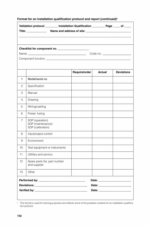
152
Format for an installation qualifi cation protocol and report (continued)a
Validation protocol _________ Installation Qualifi cation _________ Page _____ of _____
Title: ______________ Name and address of site: ________________________________
________________________________________________________________________________
Checklist for component no. ______________________
Name: _________________________________________ Code no.: ____________________
Component function: ____________________________________________________________
Require/order Actual Deviations
1 Model/serial no.
2 Specifi cation
3 Manual
4 Drawing
5 Wiring/cabling
6 Power, fusing
7 SOP (operation)SOP (maintenance)SOP (calibration)
8 Input/output control
9 Environment
10 Test equipment or instruments
11 Utilities and service
12 Spare parts list, part numberand supplier
13 Other
Performed by: _________________________________ Date: _______________________
Deviations: _____________________________________ Date: _______________________
Verifi ed by: _____________________________________ Date: _______________________
a This format is used for training purposes and refl ects some of the possible contents for an installation qualifi ca-tion protocol.
TSR2006_Annexs1_5.indd 152TSR2006_Annexs1_5.indd 152 4.5.2006 16:13:014.5.2006 16:13:01

153
Format for an installation qualifi cation protocol and report (continued)a
Validation protocol _________ Installation Qualifi cation _________ Page _____ of _____
Title: ______________ Name and address of site: ________________________________
________________________________________________________________________________
Deviation report
Deviations: _____________________________________________________________________
________________________________________________________________________________
________________________________________________________________________________
__________________________________________________________________________________________________
__________________________________________________________________________________________________
_________________________________________________________________________________________________
_________________________________________________________________________________________________
Justifi cation for acceptance
________________________________________________________________________________
________________________________________________________________________________
__________________________________________________________________________________________________________________
__________________________________________________________________________________________________________________
__________________________________________________________________________________________________________________
__________________________________________________________________________________________________________________
__________________________________________________________________________________________________________________
__________________________________________________________________________________________________________________
Impact on operation:
________________________________________________________________________________
________________________________________________________________________________
____________________________________________________________________________________________________
____________________________________________________________________________________________________
____________________________________________________________________________________________________
____________________________________________________________________________________________________
____________________________________________________________________________________________________
____________________________________________________________________________________________________
Report written by: _______________________________ Date: _______________________
a This format is used for training purposes and refl ects some of the possible contents for an installation qualifi ca-tion protocol.
TSR2006_Annexs1_5.indd 153TSR2006_Annexs1_5.indd 153 4.5.2006 16:13:014.5.2006 16:13:01
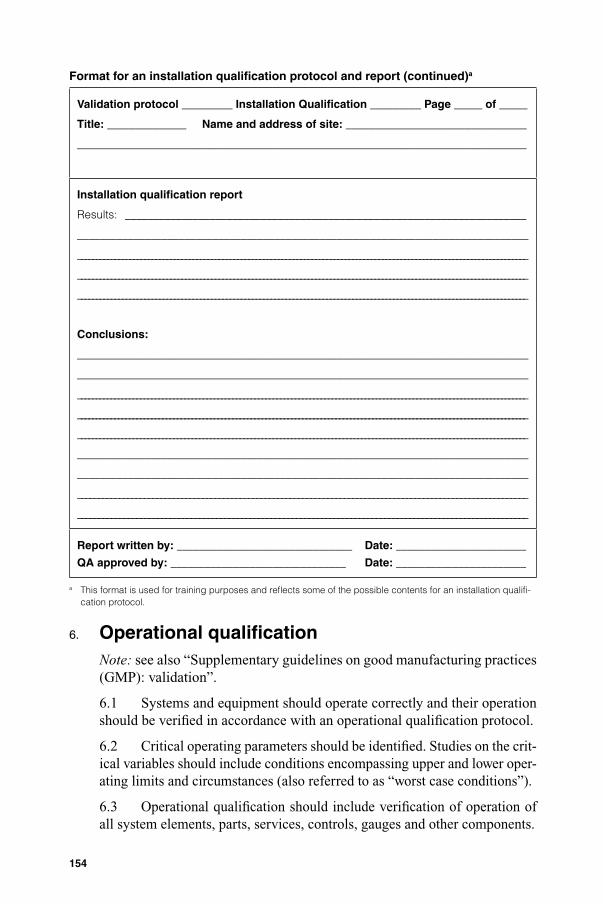
154
Format for an installation qualifi cation protocol and report (continued)a
Validation protocol _________ Installation Qualifi cation _________ Page _____ of _____
Title: ______________ Name and address of site: ________________________________
________________________________________________________________________________
Installation qualifi cation report
Results: _______________________________________________________________________
________________________________________________________________________________
_________________________________________________________________________________________________________________________
_________________________________________________________________________________________________________________________
_________________________________________________________________________________________________________________________
Conclusions:
________________________________________________________________________________
________________________________________________________________________________
__________________________________________________________________________________________________________________________
__________________________________________________________________________________________________________________________
__________________________________________________________________________________________________________________________
________________________________________________________________________________
________________________________________________________________________________
____________________________________________________________________________________________________________
___________________________________________________________________________________________________________
Report written by: _______________________________ Date: _______________________
QA approved by: _______________________________ Date: _______________________
a This format is used for training purposes and refl ects some of the possible contents for an installation qualifi -cation protocol.
6. Operational qualifi cationNote: see also “Supplementary guidelines on good manufacturing practices (GMP): validation”.
6.1 Systems and equipment should operate correctly and their operation should be verifi ed in accordance with an operational qualifi cation protocol.
6.2 Critical operating parameters should be identifi ed. Studies on the crit-ical variables should include conditions encompassing upper and lower oper-ating limits and circumstances (also referred to as “worst case conditions”).
6.3 Operational qualifi cation should include verifi cation of operation of all system elements, parts, services, controls, gauges and other components.
TSR2006_Annexs1_5.indd 154TSR2006_Annexs1_5.indd 154 4.5.2006 16:13:014.5.2006 16:13:01

155
6.4 There should be documented records for the verifi cation of operation (operational qualifi cation report) to indicate the satisfactory operation.
6.5 Standard operating procedures for the operation should be fi nalized and approved.
6.6 Training of operators for the systems and equipment should be pro-vided, and training records maintained.
6.7 Systems and equipment should be released for routine use after completion of operational qualifi cation, provided that all calibration, clean-ing, maintenance, training and related tests and results were found to be acceptable.
Format for an operational qualifi cation protocola
Validation protocol _________ Operational Qualifi cation ________ Page _____ of _____
Title: ______________ Name of Facility: _________________________________________
________________________________________________________________________________
Validation Protocol # ____________________ Operational Qualifi cation _______________
Title ____________________________________________________________________________
________________________________________________________________________________
Protocol written by _______________________________________________________________
Departmental Approval by ____________________________________ Date ____________
QA Approval by ______________________________________________ Date ____________
Objective
To determine that the system/equipment operates according to specifi cations, and to record all relevant information and data to demonstrate that the system/equipment func-tions as expected.
Scope
To be performed after installation, modifi cation or relocation, after the Installation Qualifi -cation has been completed.
Responsibility
Person responsible for operating the system/equipment will perform the qualifi cation and record the information.
The supervisor will supervise the study, verify the completion of the records, write the deviation report and the Operational Qualifi cation (OQ) Report.
Qualify Assurance will review and approve the OQ protocol and report.
a This format is used for training purposes and refl ects some of the possible contents for an operational qualifi -cation protocol.
TSR2006_Annexs1_5.indd 155TSR2006_Annexs1_5.indd 155 4.5.2006 16:13:014.5.2006 16:13:01

156
Format for an operational qualifi cation protocol (continued)a
Validation protocol _________ Operational Qualifi cation ________ Page _____ of _____
Title: ______________ Name of Facility: _________________________________________
________________________________________________________________________________
Materials, Equipment, Documents
List of calibration equipment required (Chart 1).
Materials or supplies needed to perform the Operational Qualifi cation
1 ____________________________________________________________ Code # __________
2 ____________________________________________________________ Code # __________
3 ____________________________________________________________ Code # __________
4 ____________________________________________________________ Code # __________
5 ____________________________________________________________ Code # __________
6 ____________________________________________________________ Code # __________
SOPs and datasheets for normal operations of the system under test (Chart 2).
Training records documenting that operators have been trained (Chart 2).
Manuals for equipment (Chart 2).
Procedure
Test and record calibration data for calibrating apparatus and instruments (Chart 1).
Test and record operative condition of control points and alarms (Chart 3).
Test and record outputs (Chart 4).
List of calibration requirements for the system under test and records of the calibration of the system (Chart 5).
Measure and record the results of specifi c challenge to the system in normal and worst case situation where appropriate (Chart 6).
Record any deviations to the procedures performed.
Prepare a Deviation Report including the justifi cation of acceptance and impact on the operation.
Prepare an Operational Qualifi cation Report. This should include date study initiated; date completed; observations made; problems encountered; completeness of informa-tion collected; summary of deviation report; results of control/alarm tests; sample data if appropriate; location of original data; other information relevant to the study; and conclu-sions on the validity of the equipment/system operations.
Submit QA for review and approval.
a This format is used for training purposes and refl ects some of the possible contents for an operational qualifi -cation protocol.
TSR2006_Annexs1_5.indd 156TSR2006_Annexs1_5.indd 156 4.5.2006 16:13:014.5.2006 16:13:01

157
Format for an operational qualifi cation protocol (continued)a
Validation protocol _________ Operational Qualifi cation ________ Page _____ of _____
Title: ______________ Name of Facility: _________________________________________
________________________________________________________________________________
Preparation
Chart 1: Calibrating apparatus and instruments.
Apparatus/Instrument Calibration method Calibration date
_____________________ ________________________ _______________________
_____________________ ________________________ _______________________
_____________________ ________________________ _______________________
_____________________ ________________________ _______________________
_____________________ ________________________ _______________________
_____________________ ________________________ _______________________
_____________________ ________________________ _______________________
_____________________ ________________________ _______________________
_____________________ ________________________ _______________________
_____________________ ________________________ _______________________
_____________________ ________________________ _______________________
_____________________ ________________________ _______________________
_____________________ ________________________ _______________________
_____________________ ________________________ _______________________
_____________________ ________________________ _______________________
_____________________ ________________________ _______________________
_____________________ ________________________ _______________________
Performed by: _____________________________________________ Date ____________
Deviations: ____________________________________________________________________
_______________________________________________________________________________
_______________________________________________________________________________
_______________________________________________________________________________
Verifi ed by: ________________________________________________ Date ____________
a This format is used for training purposes and refl ects some of the possible contents for an operational qualifi -cation protocol.
TSR2006_Annexs1_5.indd 157TSR2006_Annexs1_5.indd 157 4.5.2006 16:13:024.5.2006 16:13:02
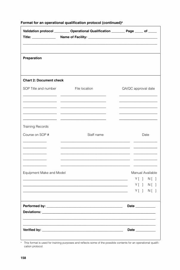
158
Format for an operational qualifi cation protocol (continued)a
Validation protocol _________ Operational Qualifi cation ________ Page _____ of _____
Title: ______________ Name of Facility: _________________________________________
________________________________________________________________________________
Preparation
Chart 2: Document check
SOP Title and number File location QA/QC approval date
____________________ ___________________________ _______________________
____________________ ___________________________ _______________________
____________________ ___________________________ _______________________
____________________ ___________________________ _______________________
____________________ ___________________________ _______________________
Training Records
Course on SOP # Staff name Date
______________ _________________________________________ ______________
______________ _________________________________________ ______________
______________ _________________________________________ ______________
______________ _________________________________________ ______________
______________ _________________________________________ ______________
Equipment Make and Model Manual Available
______________________________________________________________ Y [ ] N [ ]
______________________________________________________________ Y [ ] N [ ]
______________________________________________________________ Y [ ] N [ ]
Performed by: _____________________________________________ Date ____________
Deviations: ____________________________________________________________________
_______________________________________________________________________________
_______________________________________________________________________________
Verifi ed by: ________________________________________________ Date ____________
a This format is used for training purposes and refl ects some of the possible contents for an operational qualifi -cation protocol.
TSR2006_Annexs1_5.indd 158TSR2006_Annexs1_5.indd 158 4.5.2006 16:13:024.5.2006 16:13:02

159
Format for an operational qualifi cation protocol (continued)a
Validation protocol _________ Operational Qualifi cation ________ Page _____ of _____
Title: ______________ Name of Facility: _________________________________________
________________________________________________________________________________
Results
Chart 3: Control points and alarms.
Control point/Alarm Results Date
_____________________ ______________________________________ _______________
_____________________ ______________________________________ _______________
_____________________ ______________________________________ _______________
_____________________ ______________________________________ _______________
_____________________ ______________________________________ _______________
_____________________ ______________________________________ _______________
_____________________ ______________________________________ _______________
_____________________ ______________________________________ _______________
_____________________ ______________________________________ _______________
_____________________ ______________________________________ _______________
_____________________ ______________________________________ _______________
_____________________ ______________________________________ _______________
_____________________ ______________________________________ _______________
_____________________ ______________________________________ _______________
_____________________ ______________________________________ _______________
_____________________ ______________________________________ _______________
_____________________ ______________________________________ _______________
Performed by: _____________________________________________ Date ____________
Deviations: ____________________________________________________________________
_______________________________________________________________________________
_______________________________________________________________________________
Verifi ed by: ________________________________________________ Date ____________
a This format is used for training purposes and refl ects some of the possible contents for an operational qualifi -cation protocol.
TSR2006_Annexs1_5.indd 159TSR2006_Annexs1_5.indd 159 4.5.2006 16:13:024.5.2006 16:13:02

160
Format for an operational qualifi cation protocol (continued)a
Validation protocol _________ Operational Qualifi cation ________ Page _____ of _____
Title: ______________ Name of Facility: _________________________________________
________________________________________________________________________________
Results
Chart 4: Outputs
Outputs Results Date
_____________________ ______________________________________ _______________
_____________________ ______________________________________ _______________
_____________________ ______________________________________ _______________
_____________________ ______________________________________ _______________
_____________________ ______________________________________ _______________
_____________________ ______________________________________ _______________
_____________________ ______________________________________ _______________
_____________________ ______________________________________ _______________
_____________________ ______________________________________ _______________
_____________________ ______________________________________ _______________
_____________________ ______________________________________ _______________
_____________________ ______________________________________ _______________
_____________________ ______________________________________ _______________
_____________________ ______________________________________ _______________
_____________________ ______________________________________ _______________
_____________________ ______________________________________ _______________
_____________________ ______________________________________ _______________
Performed by: _____________________________________________ Date ____________
Deviations: ____________________________________________________________________
_______________________________________________________________________________
_______________________________________________________________________________
Verifi ed by: ________________________________________________ Date ____________
a This format is used for training purposes and refl ects some of the possible contents for an operational qualifi -cation protocol.
TSR2006_Annexs1_5.indd 160TSR2006_Annexs1_5.indd 160 4.5.2006 16:13:024.5.2006 16:13:02
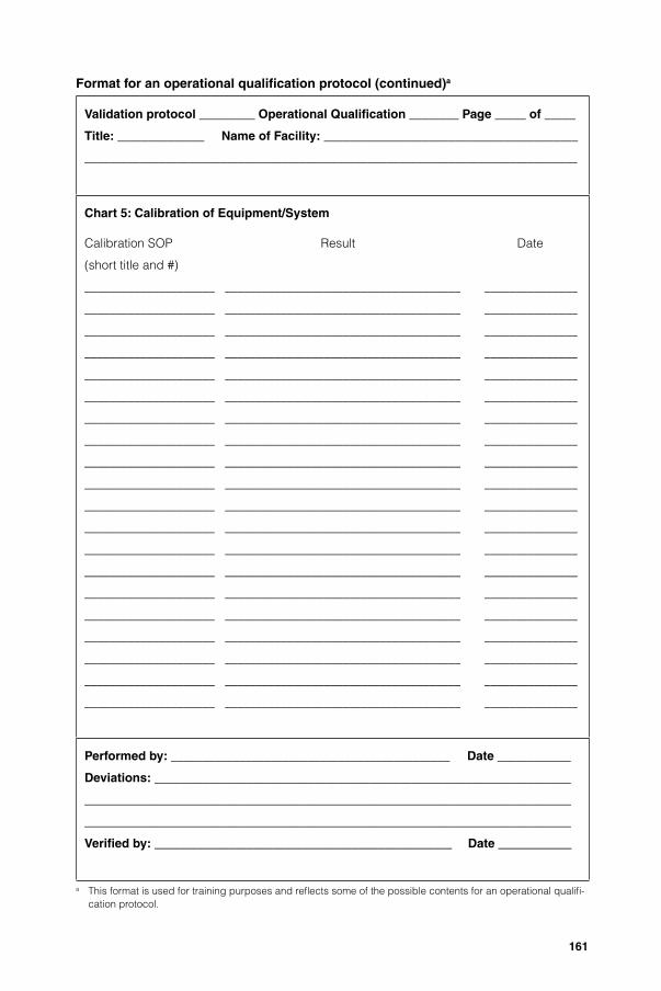
161
Format for an operational qualifi cation protocol (continued)a
Validation protocol _________ Operational Qualifi cation ________ Page _____ of _____
Title: ______________ Name of Facility: _________________________________________
________________________________________________________________________________
Chart 5: Calibration of Equipment/System
Calibration SOP Result Date
(short title and #)
_____________________ ______________________________________ _______________
_____________________ ______________________________________ _______________
_____________________ ______________________________________ _______________
_____________________ ______________________________________ _______________
_____________________ ______________________________________ _______________
_____________________ ______________________________________ _______________
_____________________ ______________________________________ _______________
_____________________ ______________________________________ _______________
_____________________ ______________________________________ _______________
_____________________ ______________________________________ _______________
_____________________ ______________________________________ _______________
_____________________ ______________________________________ _______________
_____________________ ______________________________________ _______________
_____________________ ______________________________________ _______________
_____________________ ______________________________________ _______________
_____________________ ______________________________________ _______________
_____________________ ______________________________________ _______________
_____________________ ______________________________________ _______________
_____________________ ______________________________________ _______________
_____________________ ______________________________________ _______________
Performed by: _____________________________________________ Date ____________
Deviations: ____________________________________________________________________
_______________________________________________________________________________
_______________________________________________________________________________
Verifi ed by: ________________________________________________ Date ____________
a This format is used for training purposes and refl ects some of the possible contents for an operational qualifi -cation protocol.
TSR2006_Annexs1_5.indd 161TSR2006_Annexs1_5.indd 161 4.5.2006 16:13:024.5.2006 16:13:02

162
Format for an operational qualifi cation protocol (continued)a
Validation protocol _________ Operational Qualifi cation ________ Page _____ of _____
Title: ______________ Name of Facility: _________________________________________
________________________________________________________________________________
Chart 6: Specifi c challenge of the equipment or system
Test in normal conditions:
Test of worst case situation:(e.g. start-up after shutdown, temperature recovery time, centrifuge imbalance)
Performed by: _____________________________________________ Date ____________
Deviations: ____________________________________________________________________
_______________________________________________________________________________
_______________________________________________________________________________
Verifi ed by: ________________________________________________ Date ____________
a This format is used for training purposes and refl ects some of the possible contents for an operational qualifi -cation protocol.
TSR2006_Annexs1_5.indd 162TSR2006_Annexs1_5.indd 162 4.5.2006 16:13:024.5.2006 16:13:02

163
Format for an operational qualifi cation protocol (continued)a
Validation protocol _________ Operational Qualifi cation ________ Page _____ of _____
Title: ______________ Name of Facility: _________________________________________
________________________________________________________________________________
Deviation Report
Deviation(s):
Justifi cation for acceptance:
Impact on operation:
Written by: ________________________________________________ Date ____________
a This format is used for training purposes and refl ects some of the possible contents for an operational qualifi -cation protocol.
TSR2006_Annexs1_5.indd 163TSR2006_Annexs1_5.indd 163 4.5.2006 16:13:034.5.2006 16:13:03
164
Format for an operational qualifi cation protocol (continued)a
Validation protocol _________ Operational Qualifi cation ________ Page _____ of _____
Title: ______________ Name of Facility: _________________________________________
________________________________________________________________________________
Operational Qualifi cation Report
Results:
Conclusions:
Written by: _________________________________________________ Date ____________
QA approved by: ____________________________________________ Date ____________
a This format is used for training purposes and refl ects some of the possible contents for an operational qualifi -cation protocol.
TSR2006_Annexs1_5.indd 164TSR2006_Annexs1_5.indd 164 4.5.2006 16:13:034.5.2006 16:13:03

165
7. Performance qualifi cationNote: see also “Supplementary guidelines on good manufacturing practices (GMP): validation”.
7.1 Systems and equipment should consistently perform in accordance with design specifi cations. The performance should be verifi ed in accordance with a performance qualifi cation protocol.
7.2 There should be documented records for the verifi cation of perfor-mance (performance qualifi cation report) to indicate the satisfactory per-formance over a period of time. Manufacturers should justify the selected period over which performance qualifi cation is done.
Format for a performance qualifi cation protocola
Validation protocol _________ Performance Qualifi cation _________ Page _____ of _____
Title: ______________________ Name of facility: ____________________________________
_________________________________________________________________________________
Validation Protocol # _______________________ Performance Qualifi cation
Title ____________________________________________________________________________
________________________________________________________________________________
Protocol written by _______________________________________________________________
Departmental Approval by ____________________________________ Date ____________
QA Approval by ______________________________________________ Date ____________
Objective
To determine that the systems/equipment perform as intended by repeatedly running the system on its intended schedules and recording all relevant information and data. Results must demonstrate that performance consistently meets pre-determined specifi cations under normal conditions, and where appropriate for worst case situations.
Scope
To be performed after the Installation and Operational Qualifi cation have been completed and approved.
To be performed after installation, modifi cation or relocation and for re-validation at appropriate intervals.
Each piece of equipment must be validated before it serves another piece of equipment/system during validation of the latter (e.g. water system before steam generator; steam generator before autoclave).
a This format is used for training purposes and refl ects some of the possible contents for a performance qualifi -cation protocol.
TSR2006_Annexs1_5.indd 165TSR2006_Annexs1_5.indd 165 4.5.2006 16:13:034.5.2006 16:13:03

166
Format for a performance qualifi cation protocol (continued)a
Validation protocol _________ Performance Qualifi cation _________ Page _____ of _____
Title: ______________________ Name of facility: ____________________________________
_________________________________________________________________________________
Responsibility
Person responsible for operating the system or equipment will perform the qualifi cation and record the information.
The supervisor will supervise the study, verify the completion of the records and write the Deviation Report and the Performance Qualifi cation Report.
Qualify Assurance will review and approve the Performance Qualifi cation Protocol and Report.
Materials, Equipment, Documents
SOPs for normal operations of the equipment or system under test (including data record forms, charts, diagrams materials and equipment needed). Attach copies.
SOP list:
________________________________________________________________________________
________________________________________________________________________________
________________________________________________________________________________
________________________________________________________________________________
________________________________________________________________________________
________________________________________________________________________________
SOPs specifi c for performance tests (including data record forms, charts, diagrams, ma-terials and equipment needed, calculations and statistical analyses to be performed, and pre-determined specifi cations and acceptance criteria). Attach copies.
SOP list:
________________________________________________________________________________
________________________________________________________________________________
________________________________________________________________________________
________________________________________________________________________________
________________________________________________________________________________
________________________________________________________________________________
a This format is used for training purposes and refl ects some of the possible contents for a performance qualifi -cation protocol.
TSR2006_Annexs1_5.indd 166TSR2006_Annexs1_5.indd 166 4.5.2006 16:13:034.5.2006 16:13:03

167
Format for a performance qualifi cation protocol (continued)a
Validation protocol _________ Performance Qualifi cation _________ Page _____ of _____
Title: ______________________ Name of facility: ____________________________________
_________________________________________________________________________________
Procedure
Equipment: Run normal procedure three times for each use (confi guration or load) and record all required data and any deviations to the procedure.
Systems: Run for 20 consecutive working days, recording all required data and any deviations to the procedure.
Prepare the Summary Data Record Form(Chart 1).
Evaluation
Attach all completed, signed data record forms.
Complete the Summary Data Record Form (Chart 1).
Perform all required calculations and statistical analyses (Chart 2).
Compare to acceptance criteria (Chart 3).
Prepare Deviation Report including the justifi cation of acceptance and impact on the performance.
Prepare a Performance Qualifi cation Report: This should include: date study initiated; date completed; observations made; problems encountered; completeness of information collected; summary of deviation report; results of any tests; do results meet acceptance criteria; location of original data; other information relevant to the study; and conclusions on the validity of the equipment/system.
Submit Performance Qualifi cation Document to QA for review and approval.
a This format is used for training purposes and refl ects some of the possible contents for a performance qualifi -cation protocol.
TSR2006_Annexs1_5.indd 167TSR2006_Annexs1_5.indd 167 4.5.2006 16:13:034.5.2006 16:13:03
168
Format for a performance qualifi cation protocol (continued)a
Validation protocol _________ Performance Qualifi cation _________ Page _____ of _____
Title: ______________________ Name of facility: ____________________________________
_________________________________________________________________________________
Chart 1: Summary Data Record
(To be prepared for the specifi c procedure being tested)
Performed by: _____________________________________________ Date ____________
Verifi ed by: ________________________________________________ Date ____________
a This format is used for training purposes and refl ects some of the possible contents for a performance qualifi -cation protocol.
TSR2006_Annexs1_5.indd 168TSR2006_Annexs1_5.indd 168 4.5.2006 16:13:034.5.2006 16:13:03
169
Format for a performance qualifi cation protocol (continued)a
Validation protocol _________ Performance Qualifi cation _________ Page _____ of _____
Title: ______________________ Name of facility: ____________________________________
_________________________________________________________________________________
Chart 2: Calculations and Statistical Analyses
Performed by: _____________________________________________ Date ____________
Verifi ed by: ________________________________________________ Date ____________
a This format is used for training purposes and refl ects some of the possible contents for a performance qualifi -cation protocol.
TSR2006_Annexs1_5.indd 169TSR2006_Annexs1_5.indd 169 4.5.2006 16:13:044.5.2006 16:13:04
170
Format for a performance qualifi cation protocol (continued)a
Validation protocol _________ Performance Qualifi cation _________ Page _____ of _____
Title: ______________________ Name of facility: ____________________________________
_________________________________________________________________________________
Chart 3: Acceptance Criteria vs. Performance Test Results
Criteria Results Pass/Fail
__________________________ ____________________________________ _____________
__________________________ ____________________________________ _____________
__________________________ ____________________________________ _____________
__________________________ ____________________________________ _____________
__________________________ ____________________________________ _____________
__________________________ ____________________________________ _____________
__________________________ ____________________________________ _____________
__________________________ ____________________________________ _____________
__________________________ ____________________________________ _____________
__________________________ ____________________________________ _____________
__________________________ ____________________________________ _____________
__________________________ ____________________________________ _____________
__________________________ ____________________________________ _____________
__________________________ ____________________________________ _____________
__________________________ ____________________________________ _____________
__________________________ ____________________________________ _____________
__________________________ ____________________________________ _____________
__________________________ ____________________________________ _____________
__________________________ ____________________________________ _____________
__________________________ ____________________________________ _____________
__________________________ ____________________________________ _____________
__________________________ ____________________________________ _____________
__________________________ ____________________________________ _____________
__________________________ ____________________________________ _____________
__________________________ ____________________________________ _____________
__________________________ ____________________________________ _____________
Performed by: _____________________________________________ Date ____________
Verifi ed by: ________________________________________________ Date ____________
a This format is used for training purposes and refl ects some of the possible contents for a performance qualifi -cation protocol.
TSR2006_Annexs1_5.indd 170TSR2006_Annexs1_5.indd 170 4.5.2006 16:13:044.5.2006 16:13:04

171
Format for a performance qualifi cation protocol (continued)a
Validation protocol _________ Performance Qualifi cation _________ Page _____ of _____
Title: ______________________ Name of facility: ____________________________________
_________________________________________________________________________________
Deviation Report
Deviation(s):
Justifi cation for acceptance:
Impact on operation, function or process:
Written by: _____________________________________________ Date ____________
Verifi ed by: ________________________________________________ Date ____________
a This format is used for training purposes and refl ects some of the possible contents for a performance qualifi -cation protocol.
TSR2006_Annexs1_5.indd 171TSR2006_Annexs1_5.indd 171 4.5.2006 16:13:044.5.2006 16:13:04

172
Format for a performance qualifi cation protocol (continued)a
Validation protocol _________ Performance Qualifi cation _________ Page _____ of _____
Title: ______________________ Name of facility: ____________________________________
_________________________________________________________________________________
Performance Qualifi cation Report
Results:
Conclusions:
Written: _____________________________________________ Date ____________
Verifi ed by: ________________________________________________ Date ____________
a This format is used for training purposes and refl ects some of the possible contents for a performance qualifi -cation protocol.
TSR2006_Annexs1_5.indd 172TSR2006_Annexs1_5.indd 172 4.5.2006 16:13:044.5.2006 16:13:04

173
8. Requalifi cationNote: see also “Supplementary guidelines on good manufacturing practices (GMP): validation”.
8.1 Requalifi cation of systems and equipment should be done in accor-dance with a defi ned schedule. The frequency of requalifi cation may be determined on the basis of factors such as the analysis of results relating to calibration, verifi cation and maintenance.
8.2 There should be periodic requalifi cation.
8.3 There should be requalifi cation after changes. The extent of requali-fi cation after the change should be justifi ed based on a risk-assessment of the change. Requalifi cation after change should be considered as part of the change control procedure.
9. Qualifi cation of “in-use” systems and equipment9.1 There should be data to support and verify the suitable operation and performance of systems and equipment that have been “in use” for a period of time, and which had not been subjected to installation and or operational qualifi cation.
9.2 These should include operating parameters and limits for critical variables, calibration, maintenance and preventive maintenance, standard operating procedures (SOPs) and records.
10. ReferenceA WHO guide to good manufacturing practice (GMP) requirements. Part 2: Validation. Geneva, Global Programme for Vaccines and Immu-nization, Vaccine Supply and Quality, Global Training Network, World Health Organization, 1997 (WHO/VSQ/97.02).
TSR2006_Annexs1_5.indd 173TSR2006_Annexs1_5.indd 173 4.5.2006 16:13:044.5.2006 16:13:04

174
Appendix 7Non-sterile process validation
1. Principle2. Scope3. General4. Prospective validation5. Concurrent validation6. Retrospective validation7. Revalidation8. Change control
1. Principle1.1 Process validation provides documented evidence that a process is capable of reliably and repeatedly rendering a product of the required quality.
1.2 The principles of planning, organizing and performing process valida-tion are similar to those for qualifi cation. It should be done in accordance with process validation protocols, data should be collected and reviewed against predetermined acceptance criteria, and refl ected in process validation reports.
2. Scope2.1 These guidelines describe the general aspects of process validation for the manufacture of non-sterile fi nished products.
2.2 Normally process validation should cover at least the critical steps and parameters (e.g. those that may have an impact on the quality of the product) in the process of manufacturing a pharmaceutical product.
3. General3.1 The policy and approach to process validation should be docu-mented, e.g. in a validation master plan, and should include the critical pro-cess steps and parameters.
3.2 Process validation should normally begin only once qualifi cation of support systems and equipment is completed. In some cases process valida-tion may be conducted concurrently with performance qualifi cation.
3.3 Process validation should normally be completed prior to the manu-facture of fi nished product that is intended for sale (prospective validation).Process validation during routine production may also be acceptable (con-current validation).
TSR2006_Annexs1_5.indd 174TSR2006_Annexs1_5.indd 174 4.5.2006 16:13:044.5.2006 16:13:04

175
4. Prospective validation4.1 Critical factors or parameters that may affect the quality of the fi n-ished product should be identifi ed during product development. To achieve this, the production process should be broken down into individual steps, and each step should be evaluated (e.g. on the basis of experience or theoretical considerations).
4.2 The criticality of these factors should be determined through a “worst-case” challenge where possible.
4.3 Prospective validation should be done in accordance with a valida-tion protocol. The protocol should include:
— a description of the process;— a description of the experiment;— details of the equipment and/or facilities to be used (including measur-
ing or recording equipment) together with its calibration status;— the variables to be monitored;— the samples to be taken — where, when, how, how many and how much
(sample size);— the product performance characteristics/attributes to be monitored,
together with the test methods;— the acceptable limits;— time schedules;— personnel responsibilities; and— details of methods for recording and evaluating results, including statis-
tical analysis.
4.4 All equipment, the production environment and analytical testing methods to be used should have been fully validated (e.g. during installation qualifi cation and operational qualifi cation).
4.5 Personnel participating in the validation work should have been appropriately trained.
4.6 Batch manufacturing documentation to be used should be prepared after these critical parameters of the process have been identifi ed, and machine settings, component specifi cations and environmental conditions have been determined and specifi ed.
4.7 A number of batches of the fi nal product should then be produced. The number of batches produced in this validation exercise should be suf-fi cient to allow the normal extent of variation and trends to be established and to provide suffi cient data for evaluation.
4.8 Data within the fi nally agreed parameters, from at least three con-secutive batches, giving product of the desired quality may be considered to constitute a proper validation of the process.
TSR2006_Annexs1_5.indd 175TSR2006_Annexs1_5.indd 175 4.5.2006 16:13:044.5.2006 16:13:04
176
4.9 The batches should be of the same size, and should be the same as the batch size intended in full-scale production. Where this is not possible, the reduced batch size should be considered in the design of the protocol and when full-scale production starts, the validity of any assumptions made should be demonstrated.
4.10 Extensive testing should be performed on the product at various stages during the manufacturing process of the batches, including on the fi nal product and its package.
4.11 The results should be documented in the validation report. As a min-imum, the report should include:
• a description of the process: batch/packaging document, including details of critical steps;
• a detailed summary of the results obtained from in-process and fi nal testing, including data from failed tests. When raw data are not in-cluded, reference should be made to the sources used and where it can be found;
• any work done in addition to that specifi ed in the protocol, or any deviations from the protocol should be formally noted along with an explanation;
• a review and comparison of the results with those expected; and• formal acceptance or rejection of the work by the team or persons des-
ignated as being responsible for the validation, after completion of any corrective action or repeated work.
4.12 A conclusion and recommendation should be made on the extent of monitoring and the in-process controls necessary for routine production, on the basis of the results obtained.
4.13 The conclusion and recommendation should be incorporated into the batch manufacturing and batch packaging documents and/or standard operating procedures (SOPs) for routine use. Limits and frequencies of test-ing and monitoring should be specifi ed. Actions to be taken in the event of the limits being exceeded should be specifi ed.
4.14 Batches manufactured as part of the validation exercise, and intend-ed to be sold or supplied, should have been manufactured under conditions that comply fully with the requirements of good manufacturing practice and the marketing authorization (where applicable).
5. Concurrent validation5.1 In certain cases, it may be appropriate to validate a process during routine production, e.g. where the product is a different strength of a previ-ously validated product, a different tablet shape or where the process is well understood.
TSR2006_Annexs1_5.indd 176TSR2006_Annexs1_5.indd 176 4.5.2006 16:13:054.5.2006 16:13:05

177
5.2 The decision to carry out concurrent validation should be made by appropriately authorized personnel.
5.3 It is essential that the premises and equipment to be used during concurrent validation have been previously qualifi ed.
5.4 Prospective validation should be done in accordance with a valida-tion protocol.
5.5 The results should be documented in the validation report.
6. Retrospective validation 6.1 Retrospective validation is based on a comprehensive review of his-torical data to provide the necessary documentary evidence that the process is doing what it is believed to do. This type of validation also requires the preparation of a protocol, the reporting of the results of the data review, a conclusion and a recommendation.
6.2 Retrospective validation is not the preferred method of validation and should be used in exceptional cases only. It is acceptable only for well-estab-lished processes and will be inappropriate where there have been changes in the composition of the product, operating procedures or equipment.
6.3 Suffi cient data should be reviewed to provide a statistically signifi -cant conclusion.
6.4 When the results of retrospective validation are considered satisfac-tory, this should serve only as an indication that the process does not need to be subjected to validation in the immediate future.
7. RevalidationNote: see main text on “Validation”. The need for periodic revalidation of non-sterile processes is considered to be a lower priority than for sterile processes.
7.1 In the case of standard processes using conventional equipment, a data review similar to that which would be required for retrospective vali-dation may provide an adequate assurance that the process continues to be under control. The following points should also be considered:
— the occurrence of any changes in the master formula, methods, starting material manufacturer, equipment and/or instruments;
— equipment calibrations and preventive maintenance carried out;— standard operating procedures (SOPs); and— cleaning and hygiene programme.
TSR2006_Annexs1_5.indd 177TSR2006_Annexs1_5.indd 177 4.5.2006 16:13:054.5.2006 16:13:05

178
8. Change controlNote: see main text on “Validation”.
8.1 Products manufactured by processes that have been subjected to changes should not be released for sale without full awareness and consid-eration of the change and its impact on the process validation.
8.2 Changes that are likely to require revalidation may include:
— changes in the manufacturing process (e.g. mixing times, drying tem-peratures);
— changes in the equipment (e.g. addition of automatic detection systems);
— production area and support system changes (e.g. rearrangement of ar-eas or a new water treatment method);
— transfer of processes to another site; and— unexpected changes (e.g. those observed during self-inspection or dur-
ing routine analysis of process trend data).
TSR2006_Annexs1_5.indd 178TSR2006_Annexs1_5.indd 178 4.5.2006 16:13:054.5.2006 16:13:05