aniiv1ated grai)i-i i cs - university of canterbury
TRANSCRIPT

COSC460
.ANIIV1ATED
GRAI)I-I I CS
FCJf{
NE\Xl ZEAL;\ND.
Computer Science Depertrnent. 1
University of C8nterbury. October~ 1985.
.J.R.A. Co 111 er.

2
2 overview of Animated Grar;rhics in Television 2 2.1 Computer grephics in the television industry 2 2.2 Applications end their resource requirements 3 2.:~ lrnplementetion issues in animation systems for television 4 2.4 DedictJted grephics machines 6 2.5 Grophics facilities ewailable ot TVNZ 6
3 JL~si gn_ deci sjQns i.D.J11e i rr:m 1 errt~lilt'Jtion oL on flllitlli'!teg_ groQhics s~1stem for TV~Z 8
3. 1 A lterneti ve opproaches to the project 8 3.2 Software components of on animated solid modelling system
for UNIX on the VAX-11 /750 10
4 Selectiot) and !11Qdification of. the c~n1.a!l_g[QQhics QBCkf!9f 11 4. 1 Rf~qui rements of the grophi cs pt'lckeJge 11 4.2 Choice of grephi cs pocl<oge 11 4.3 A description of Unigrflfix 12
5 mterocUY.!1_§Qi tirwln.tlli.U es 16 5.1 Description of the Object Definition Editor 16 5.2 Creation of the Animation Commemd File- Scene Editor 19 5.~~ r~efining the user interfoce
- sweep editing ond shell control 20 5.4 Local design
-implementing the editors as Mecintosh applications 20
6 Anirrwt.totL(.QntrolJ'!nQ Qt§.rlli!Y 21 6.1 Commtmd f11e interpretation eJnd control
- Animation Preprocessor 21 6.2 Reasons for seperotlng the Animation Preprocessor 21 6.3 Camera control - mod1f1cotion of Ugplot 21 6.4 Advantages end disadvantages of fllm es a transfer mecJiurn 22 6.5 Test clips- frame skipping 22
1 Results 23
8 Evaluation 23
Armeodfx I :Extensions to the Unfgrafix language 27
81mendix II :Description of the drawing plane tnmsformt:Jtions 30

The purpose of this project wos to explore methods of exponding Uw
computer graphics focflities ovailoble to Television New ZefllondJ
portfculorly in the field of animated! grophics. At presentJ their in house
equipment is incepable of supporting many of their requirementsJ and
producers ore often unable to include graphics sequences because of the
cost of commercial graphics services.
The initial part of the project required research in the field of gre~pf1ics
systems and. their implementationJ ond e~lso t1 survE!tJ of the requirements
and currently available facilities at TVNZ. Following this, a prototype
animoted grBphics system based on LlnlversitLI equipment we1s proposed Bnd
is now pewtly implemented.
This report contains a review of the initial reseorch and the factors
leading to the mojor design decisions. It also includes a description of the
proposed animation systemJ with fl more detailE1cl expleme:1tion of the ports
of the system which hove now been implemented.
2. Overview of Animated Gronhi~i~ i!LJeh~y.ision
2. 1 Cornm!i.QIJffiwhics inJJlfLl(?Je~ti si onJnQ!t~iCY
Over the last decadeJ television cornpt:mies throughout the world have
become increasingly aware of the potential applications of computer
graphics in television programmes. Computer graphics can replace time"·
consuming monual tasksJ such as subtitle generolion, and they can olso be
used to creete images which would otherwise rBquire prohibitivelu
e><pensive modelling or hand animationJ or which could not be produced b~l
manual methods.
Currently, the most frequent users of computer graphics on television
are edverti sers. They have recognised that graphics can ho 1 d o vi ewer's
fJltention ~ perhaps portly because of the novelty of the technology os well
os the voriety of visuEJl imoges which can be created. Tbey elso hove the
financial resources to offord television-quality grophics.
t'lany te 1 evi si on programmes have also f ouncl uses for graphics. High
qut~lHy enimated graphics oppeeJr in continuitu breoks and progromme title 2

same reasoning as in the case of aclvert i sernents. Use of one-off computer
grapl·dcs within television progrennrnes is ot present limited by cost.
Applications which can be supported by low-cost equipment, such as
generation of character sequences, static diagrams and bar graphs, are
common 1 y us eel in educati ont~l and current Elff oi rs programmes. Producers
of these and other progremmes would use more grephi cs end rnore
sophisticated graphics if they were readiltJ available.
2.2 ArmlicoUons (1fid their Re~.ourc§_!Sem!tr~m~n.!Ji.
2.£_1 fS~C!l_l~ttig lmnOf:£
The most fldvanced app 1 i cations of computer grephi cs in film find
television involve cree~ting reelist1c animated scenes. These mtly be wholly
computer generated or developed by digitising end memipulating existing
pictqres. Such tBsks require. large amounts of memonJ and processing
power, and this usueilly entails t11e twe of a super-computer etncl decl'icated
hordware.
ReolisUc static imBges can also be produced using paintin[l packages.
These do not represent scenes lnterrH'Jlly as collections of sept~rete three··
dimensional objects but simply ollow the user to "ptllnt" picttwes frorn
defined textures, colours and shapes. Paintlng pacl<oges con be used for
generBtlng still pictures such es programme and channel logos, but their
potential for animation is limited since each fnm1e must still be drown
individuolly. Such systems ore ovedlable on mini-computers t~ncl lfJrge
micros.
2. 2. 2 s iLI1~Arm.llii!..!lQn~_;Jj 1 c roc o mm)t e rs!
Microcomputer-based graphics systems are sufficient for generating
text, grf:lphs, tind simple drawings. They can t~lso produce some sirnple
two-dimensional anirne~tion sequences. The rnt~in 11rnitation of
microcomputers is their lt1ck of rnemor~1, which puts severe restrictions
on the resolution of their graphic systems, the complexity of scenE!S which
can be described and the 1 ength of the graphics merni pul ot ion programs. 3

Much of the interest in computer graphics for television is directed
towerds systems which ore cepable of producing threE!-dimensionell
animation of stylized irneges. These systems manipulatE! ancl displey
scenes composed of pre-defined ob j eels 1Nhose position tmd orientation in
3-D spece can be tlltered independently in etJch frarne. The objects ewe
.often defined os composites of simpler structures~ end ore besed
ultimCitely on o smt~ll set of system-defined picture elements.
Such systems offer vorious primitive elements. The simpler ones
provide points end line segments for "wire freme" dnn·vings. r·tost will
include polygons which cen be used to construct solid objects. 1'1ore
advanced systems moy offer curves tmd generol plener surfaces, end in
some ceJses curved surfBces.
Other features to be considered include the variety of colours offered,
directionellight sources~ she~d.ows end textures.
Although it is occepted that the computl ng povver requi rt1cl for rtH'Il i sti c
systerns would be too costly for all but world inclw::tr~t lef.lclers~ simple
solid modE:dling systems cem be implernentecl on computers which would be
accessible to most television companies. The project has thereforE!
concentrated on the level of animated grophics produced by bosic solid
mode 11 i ng techniques .
.2 ... ~_l.mlllQtnilll18t i orLI SS~l8S ln_An1rn~110tL.~YQ!.fill!S lQLI.fil 81/iQ,lQ!}
2.t3.1 Perfomonce Congraints
As solid modelling s~1sterns become more aclwmced~ the processing
power~ storage end time required to displey eBch freHne increases. One of
the most tirne-consurning tasks in displaying a scene is the elimination of
hidden surfaces. This process takes consid€.~rably longer if the betsic
surfoces are more complex : polygons Cflt1 he handled quite ee~sily; planew
surfaces with curved edges take re;ther longer; curved surfBces require
considerably greater processing time. If directionel light is used,
rendering of curved surf aces may bee orne unacceptab 1 y s 1 ow because
shflding will Ve-Jry across the surfece~ forcing output to be performed ph<el 4

hU pi;wl.
In dE!Veloping an e~nimation system for television, consideration must
be given to the development time of animated soquences, given the
oveJ1lable computing resources. Real-time emimetion is not fee~sible for
most solid modelling systems, and H is likely the~t most sequences will
have to be rcwised several times before they c1re satisfactory. As t1
~uideline, a system would be required to record a 15-30 second clip
overnight 1 n order to be acceptab 1 e.
2,3.2 HUllliill.JillfWfflC8- Desjgn_lnQUl
The quaiity of the work produced is dependent upon the ortistic ability
of the operator, end it is unref.lsonflt)le to expect ~lifted graphic ortists to
describe their designs in terms of 3-D coorclinalE!S in e graphics ltmguage.
On the other hand, the mef1ns of input must be powerful enough to provide a
full ge:ornetri c cJescri pti on of the designs.
The interface must be t'Jimed ot em ine>t.porienced user, but it i~•
necessary to assume that the graphic artist will be farniliar with concepts
such as basic coordinate geometry emd t~mes of proJection, emd will be
willing to use an interBctive design system.
A good system wi 11 usually pro vi de user- friendly drawing peckages and
editors, together with speci a I graph1 cs input devices such as eli git i sers .
.2J:~. :t._r e 1 e ~i2.Lo n sy_~hun.Jn!fliliJ~ft.:__Gr~nht~§_Q!ll WJJ
The interface bet ween the computer and tht:l television s~1stom poses a
number of difficulties. The output device rnust be able to generEJte the
basic picture elements used in the graphics system. It must e~lso hewe
sufficient resolution to produce e~ smooth imege on the television screen.
Given thot 625 horizontal lines are used in television, o suitable output
device shoul cJ pro vi de obout 1 000 x 600 pixels with a range of co 1 ours. A
direct interface cem be implemented by writing the output to e frame
buffer or grephics terminal, emd then emplotJing specialised hordwt'lre to
convert the red, green emd blue signals resulting from e scan of U"1e
completed image to the signel forrnBt used in t1 vidc~o tape recorder. Tl1e 5

real-time animation is usually not fee~sible for sc£mes which include solid
objects.
There are o nurnber of other approachet: to this problem. ~;orne of these
use fi 1m as en 1 ntermecli f:lte medi urn bet ween the grflphi cs system oncl
te 1 evi si on. The Moving Picture Cornpany in Lonc1on lwve deve 1 oped EJ system
for tnmsferring computer graphics tp film by loser, but fJ less costly
e;lternotive is to pr1otogroph frEJmes from o high-resolution graphics
terminol.
~. Declicoted GroQhics tl!!.Qhines
These problems have led to the development of dedicBted machines for
the production of ani mtiled graphics for film and te 1 evi si on. One such
rna chine is the Eiosch FGS-4000 I which fulfils the processing power and
storage capeJcity requirements/ and also implements many of the required
functions in hewdv .. 'ore to improve speed. The Etosch hemdles e11l phases of
development from design input to the video interfece. BecC~use these
rna chines ore dedi cot eel to grepl1i cs proclucti on, theu are not mode in 1 arge
numbers t:~nd are consequently very expensive: the Bosch is priced at over
$750 000.
2~J2Dmblc? fflcilitleuvt)iloble at JVNZ
In house graphics facillties f:lt TVNZ ewe provided by Apple III
microcomputers with special memory boards ond interfece hardWE1re to
give t:~ccepteJble resolution for text and simple imt1ges in f1limited renge of
colours. There is one of these systems in Christchurch) and another two in
Wellington with larger rnernor~1 boetrds. Everu image must be proorommed
individuelly using FORTH. The present tlpplicotiont: extend the capabilities
of the Apple III's to the limit. Even for simple line drawings) production
deley is said to be unacceptable/ 6S is the e~voilEJble resolution.
A 11 other graphics must be supp 1 i ed by comrnerci 61 vi cleo production
companies/ whose major clients are etdverUsers. One cornpan~L "The ~louse
Th6t Roared" in Auckl ond/ uses a Bosch FG£;-·4000 flnd lltlt: rntlde o number 6

of clips for TVNZ in recent rnonth~;t. Eiecause of t11e equipment overheads
and the l1i ~111 pri c:es which cornmerci o 1 clients are prepared to pay~ TVNZ
can not tlfford the work produced by such companies for most one-off
app 1 i cations.
The aim of this project ¥1'eJS to explore possible methods of producing
ani mated grephi cs sequences which would be more so phi sti cated than
those produced b~l existing in house facilities~ but which would not enteil
the expense of cornmerciel11y produced clips.
11t is interesting to note that a Macintosh running t1acDrav is used as a secondary input device
on this Bosch. This inspired the use of the Macintosh as the input device for the editing
programme$ in the propo::ted t~IJZ~tem.
7

~--' Desi g.!l.J)eci si ons j rL1he lm.rtlerr.l!mJnti on of Qn
!J..ni motJHL60!J)hi cs Sy_HtJ_}JJLf OLI e 1 mu si Of_LN~)V Zco 1 nnq
3.1 AlterneJtive AP..I~rooc:hg~s to tl)e PrQjecJ
During the eorly stt~ges of the project, a number of possible approaches
wt~re su~Jgested. It wos necessC~ry to eveluate these suggestions, elnd to
considf.W other possibilities which subsequently became opparent.
lj_,_j_~ystern Elos~d on ~)~i st i ngjji.Q_[Q_pomr;ru.t~r Equi ~.'lllent
The fit·st epprooch wos to develop a set of generol graphics functions
on t11e Apple III which would reduce production tlme for stotic graphics
ond would support simple two-dimensiontll onimotion. This wos found to
be i rnprt~cti col becouse o 11 ovoi 1 ob le rnernorL~ wos fll reedy required to
produce current grophl cs sequences, cmd thet:e were on 1 y possi b 1 e when
1 ow-l eve 1 spece so vi ng techniques were emp 1 oyed.
3. t2 Ex te rnr!lJ3H!Ill1 i c ~J> tt~~J..m~tn en LjtHlLE_x i s t i ngJJJl1J!.1!L~Y~ t em The ne>~t su~mesti on wos that groplli cs sequences should be bui 1t up on o
more powerful computer, ond the resulting images looded into the Apple
III os e ~~et of primitive cornmemds. The editing, enirrwtion ond disploy
control functions would be performed on the Jerger computer, end the
primitive graphics commends for each frame would th£m be tnmsferred to
the Apple I II sqstern. '"
This opproach assumed th£~ ovailot&ility of o larger computer. At eorly
stoges it was thought that the computer used for Teletext, which is
currently under-utilized, rnight be mode oveilable for the project. This
WfiS not in f e1ct poss i b 1 e treceuse the Te 1 etext edmi ni stroll on is sepewote
from TVNZ, end it wos ellso found thtlt the full resources of the computet~
would be required when Teletext become more widely used. It wos then
suggested thflt the VAX-11/'750 fit the University of Cemterbury's
Computer Science Deportrnent could be USE!d to implement o prototype
ShiStem.
There remoinecl two major probltHY1s, however. Firstly, there WC!S no Ei

suitable method of trant\f€:!rring data from the VAX to the t·.pple; em
off ordab 1 e Post Office 1 ink waul (1 hove been too slow and there were no
cornpC!tible disc or lf.lpe devices on the two rnochines. Also~ personnel e~t
TVNZ he1d hoped thCil the grophi cs system waul c1 not be l1 mited to the
resolution of the rnodifi ed App 1 e II I.
3._L~lndepen.QJtnl AniJntl_U..QJL~Yf:JenLlJ.[i_ngJjl!Jtirensfet:
Becouse the obove options were unsolisfoctory~ it wos decided that the I
onirnotion systern should be independent of the existing focilities at TVNZ.
A prototype systern would be developed) using University equipment for oll
phoses of graphics development.
Tlw primary purpose of this prototype system wss to determine
whether tile ciWt;en method of graphics production would be viable~ before
TVNZ were committed to ony rnojor exp€mditure in hardware or software.
The prototupe system would bH implemented on the VAX) end if the results
of tile project "Nero fovourable~ TVNZ would try to obtt:~in access to a
suitobltJ computer E1l times when utilization was low.
In the prototype systern) the editing functiCJns were to be included on
u-,e VAX os well os u-,e onirnotion control end display functions. If o final
production system eventuoted~ the editing functions would probebly be
implemented on a microcomputer such tiS the Apple ~lecintosh in order to
allo'vv graphics developrnent work to be carried out flt TVNZ premises. The
output from U1e editors would bEr transferred to the larger grept1ics
processing ond display system by o movecble seconden-y storage medium.
In order to minimize costs~ grephics \'vould be transferred to the
television systern by film. 1\ stop-frorne comero would photogroph eoch
fn.'ltrw from fl high resolution grE:Jphics terminal) find the film could then be
tronsf erred to video usi l'lfl existing equipment. TVNZ technicians offered to
LnJi 1 d o camera contra 1 which could be triggered by the cornputer. It 'vVOS
sti 11 necessary to obtain o sui tab 1 o grephi cs tenni ne 1~ and for the
prototype develojJment borrowing or leasing seomed the best options.

~--l~So_flwore CorrmotWJJts oLQfl Allitr,oted ~lli_Modellin,g System
f.QLJ1IiUL9Jl1h~_YAX_: .. LlLI~ 0
Becetuse the development of on independent full colour 3-D onimotion
system would not hove been 5 vioble honours project~ it was decided tlwt
the enirnotion systern should be irnplemented E1s on extension to on
existing static ~1raphics package.
If o such o pf:lckEJge could be found~ the animation softwore would be
required to control o repeated disploy loop/ mEJking the appropriate object
trensform~Jtions between ee1ch frmne. Since the rendering ond
tnmsforrnotion cornponents would be running under the control of this
onimotion softwore~ it mode little cJifferencE! whether the package
consisted of sutrrouti nes tn- independent programs~ provided the
components could be controlled individuolly.
It Stlemed unlikely thet o graphics pocl<ege with a suitable interactive
editot- would be aveiloble~ ond in ony cose such on editor would require
modifict~tion to ollow some method of defining frome tronsforrnEJtions.
Editin~1 facilities therefore rernoinec1 low in tile list of priorities for o
r:;ui tetb 1 e grephi cs PfH.:ko~w.
Tt1E! sofhvore could Utorefore be divided into three main sections:
1. lntert:'lctive editing facilities, which would probably hc1Ve to be
deve 1 oped as part of the project.
2. An undc~rl~Jing solid rnodelling pockoge~ with rendE{ring ond tronsform
-·t'Jti on copabil i ties.
3. Ani rnoti on contra l.
Decetuse ports 1 end 3 rtdied on EJ knowledge of the rnodelling pockt:Jge~
this section wos con~~iclerecf first.
10

:LLE8(1ltiJJWJ!mts _ _pf tiJJ;:._Greplliss [~cl<qgs:
In order to be occeptoble tlw graphics system was required to meet
certain criteria :
1. It had to lw copoble of running on the VA)( under UNDt
2. It could not depend on the use of o specific output device.
3. Full 3-·D copebilHies were required, including
-object Wid scene tnmsforrnotions (rotote, scole, tronslote)
-perspective projections
.: solid ot1ject disploy (hidden line oncl foce elimination)
-window tronsfonnotions ond clipping
4. A ronge of colours hod to be definoble, preferably frorn 1·1ue/
soturat i onli ntensi ty or red/green/blue components.
~Lf.. c:hoice .P.L~J2JlD.1fllll c~·- F'Q£K~i.9g
fiecouse t11e prototype s~J~·tern Y.los intended os en experirnenl to
delE!rmine whether this eJpprooch to onirnatecJ graphics production would be
vi ob 1 E~, it wos f e 1t t11ot the expense of o cornrnerci o 1 grapt·li cs package or
suitoble CAD system would not be justified.
Tl1ere were o number of journBls which seemed likely to contain
rE!ports of grophics systerns which lieJd been developed ot educational
institutions ond which would probably be obtainable ot reasont~ble cost.
Among the sources consul ted were ACijL_S I GGRAF'H - Computer Gro~J1llg_§...
_comrluterB. .. llillt GnJ.Rhis;_~, end the Ero~QL9f the Digital EmtiJLrnE!nt
con2orot1 on U~_grs'_5oci ety.
None of tile sttsterns described met oll the l"flQUirements listed ebove.
Neverthe 1 ess, o short ··1 i st of pos~:i b 1 e pecl<oges was mode. They ore given
below with the reosons for tll(dr eventual rejection:
1. The Pascal GF!.t\SP system [7) : wos rejected because of tlr1e appcwent
inadequacy of its colour end solicl foce definition facilities.
2. The George ~vashin~~ton Univer~:ity CORE system [8]: wos running only
under Vt'lS, ond did not include enq hi elden line ond surfece removal. 11
3. Tho NGS extensions [9] to the G~vu cor~E system t:Jbove : were never
implemented.
cl. The Lt:diigh University pacl<oge [ 1 0] : wos dedicated to an extremely
expensive grephics workstation.
,1\t this point it oppeored tlwt eitheH- o more widespread seorch would
be required~ or that certein desirable facilities would hove to be excluded
frorn the list of requiremE!nts. However~ the project supervisor wos then
informed of the existence of UnigrofiX 1 o pockege developed ot UCB for
V t~X 1 '~ systems running UN I w~~.
Uni[]rofix wos eventuoll~l chosen Etf.> the most suitBble grophics ptlckoge
vvlti ch coul cl be used os o basis for the experi rnente1l oni mali on system~ end
o copy of it was obteined.
·4 ._~iA_Qt_$._~: riP tLQlLQ f U nlgntU.z
Unigrofi~~ is et collection of pro~Jroms written in C ond Pascal for
rnonipuloting end disployin[J three-dirnensionol scenes. Object2: ore definod
in term~: of Vet'licef;, wire~:, oml faces (polygons). No smooth curves or
curved surfaces ore support€.~d. Unigrofix t:lllows colour defini lion by hue I
soturotion and intE!nsityl provides till the necessery object ond viewport
tnmsformotionsl end con be used with o ronge of disploy devices. It olso
provides cornrnonds for directional light source~:.
Unfortunately~ there ore no interactive editing facilities in Unigrofix.
This is hordl~l surprising since an interEJctive systcHn would be dependent
on the type of input device, EJnd very different approaches would be
required for (se~J) fl mouse input and o digitizer input.
All scenes are described in the Unigroflx longuogel which has o
Pescol-1 ike syntex. Scene files writ ten in this language contain
definitions of vertices, wires, ff.lcesl colours, light sources~ tmd compound
objects built up from these. Scene files also contoin instances of the
objects~ eoch with o specified position, size~ ond orientotionl which will
be disployed on tile output device. Viewing options ond whole-·scenEr
tronsforrnotions oro qiven nf.: pFlt"fltnr.tors to tho prO!]rorns. A full QUide to 12
Unigrafix ancJ its langtH'I~le i~: given in tho Unigrafi)\ User's ~1anual end
J.ill!} ri ~111 11.
:~. 3.J_ __ ;&r.tw art...~~uwor1
The status of Unigrafix as a package is unclear. The programs still
cuntoi n (Jt.~buggi 11£1 code ond there ore rnony f eotures which ore brocketed
off beceJuse they do not work. Bugs in the soft wore ere noted in the manual
ontl in the prO£JI"Elrt1 comrnents. The user's monuol is doted December 1983.
Little development seerns to have occurred since then~ so it appears tht~t
any meintenence which i~: required rney ht~vo to be carried out by the users.
Two versions of tlw packoge werB supplied; tile eorlier one requires o CAD
library which wos not includell1 oml it therefore connot be used.
~L3.;2 Re.nd€lr.i11~L~oU W..f
device dependent procedures for inilielizetion, line output, polygon output
(or spem output for ro~;ter device~;), Jebel output, colour definition e~nd
device closing. ¥/henever device output is nocessewy, the progrCJm uses o
ce~se statement to i dent if~l the oppropri ete procedure. Aport from these
files, severo! modifications must be rne:~de to the other parts of the
progrom when et new devicE! is odded.
Unfortunately, none of the devices supported by Unigrofix were
ave-Jiloble for the project. A Hewlett-Pockord 2627A colour grflphics
terrninfll WfJS rnode EJVEJilotde holf-·woy through the yeer, and ugplot wos
modified to produce output for it. The terrni no 1 wos removed short! y otter
this tosk hod been completed, bul it allowed testing of the colour feotures
of Unigrofix.
Followin~l this, the Deportment ocquired o Tektronix 4012 terrninel
emulator for the 1-\pple l"lacintosh~ coiled Griffin Terminal and developed at
Reed College [ 14]. l"lodifictltion of ugplot we~s olso required before it could
be used. Although it produced onl~J black emd wbite output, this ernule,tor
wos considered suff1cient for the init1ol development of the onimoted
£ll"t!Phics system, ond it elso provided tl set of mouse interrogotion
cornmands which rm.~de it suitable for use in the interactive scene editor.
4.3.4 Device lntr.1rfBce ConsidE!rotions end Perfonnence of LlgRlot
Tests performed on simple ~~--D objects suggests that the disploy time
forms a c:onsi derab 1 e proportion of the tot a 1 time required to process end
displou Jorge, simple obJects. When the output of ugplot wos redirected
frorn Griffin Terminal too file, tl"le progrmn took considert'lbl~lless time to
complete thon when output wos written direcllhl to the terminal. When the
resulting file was disployE!d using "c()t", the Ume required was olmost os
great as wt·,en the pro~1rorn output wos displayed directly. (The ideo behind
this test wos inspired by [6J.)
t'1ost raster-seen terminals require solid faces to be fllled bye series
of horizintal scon lines ("spans"). Some~ however~ contain herd-wired
functions which allow fost filling of o polygon from the specification of
its 1/Hrtlces. The obovH result suqqests Urf1t it would be prudent to moke 14

use of tile Uni grofi )< po 1 ygon clrowi ng functions (rather than span output
functions) ·vvhc1n the terrninell supports outometic poly[IOn filling.
If tile work slot-ted in the project is to be completed~ H will be
necessary to gein occess to a colour graphics terminal on a more secure
ba~:is. For television quolit~J worl<l o high resolution terminal v'llll be
required~ emd greoter efforts should be mode to optimize the 1nterfoce for
this terminal.
15

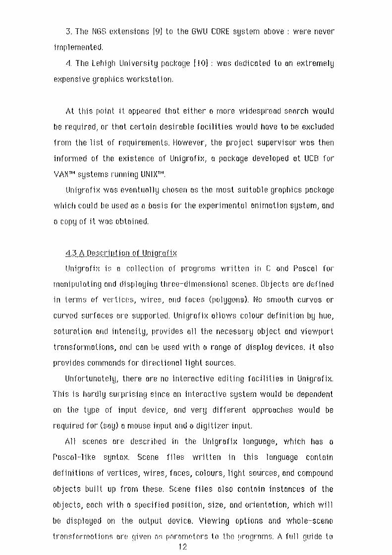
J nteroct1 ve Edit i ng_ComP-opents
of the Pr·of!.O~ed Animotjon System
Object Definition
Editor
l--\ Object Definition Files
(Ungrafilc F'onnat)
Scene Editor - defines object instances
I
... initial transfonna tions
... per frame transfonnation
Hnimation Command File
-extended Unigrafix scene file format

~j_,_jnt~ro_ct tYJL.Ed11tng.£ocjJ ittes. The des1£Jtl of on orninwted grophic:s sequence is performed in two
stoges. The ffrst stt:Jge is to dr1:1W the objects which will oppeer in the
scene. Ttlis is done using the Object Definition Editor. The second stage
involves combining the defined objects in eJ scene ond specHying the
onirne,tlon cornmemds. These opere,tions ewe performed using the Scene
Editor.
Tt1e Db j ect DE!fi ni ti on Editor is the on 1 ~~ part of the editing ond
oni n1e1ti on sofbvore wl1i ch is currently i rnp 1 ernented) but si nee it is
expeclE!d to be much the larget:t ond most complex program which must be
written for the s~1stem) the rernoining components could be produced in o
relotively short time.
5J ... Descri~!1i!liLQ1J.he Ol;!j_~.d Def_inilion Editor
The Object Definition Editor is o Poscel prognm1 which allows e
graphic e~rtist to draw o three-d1rnensione:ll object using Griffin Terminal
(q.v)) ond then writes the Unigrefix definition of the object to on Object
Definition File. It uses o cornlii notion of menu optl ons and yes/no questions
to control the sequence of operetions) and this should make it Basy for an
inexperienced operotor to use.
The editor is built oround the graphics cepobilities of Griffin Terrninol 1
a Tektronix 40 12 1 ~1 terrnintil ernuletor for the Apple Macintosh 1M developed
ot Reed College [ 14). ~louse input end graphics output ore performed
through tl library of Pescell procedures emd functions which is supplied
wHI·, the terrni nol.
The code of the Object Definition Editor is provided separately with
this report.
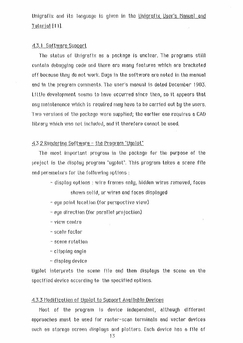
5, l,LQ!lj_ect cree_t ion,
The program is divided into two main sections. In the first) the
terrninell is set in grephics mode end the operator draws o three
dimensional obJect by requesting menu options for defining primitive
picture components (vertices, fe1ces, wires ond colours) ond following the 16

Structure of the Object Definition Editor
Initialisation
I Initialise Item. Lists I
I Set terminal for graphics
Object Definition Editor
Object Defirlition Loop
Process User Request
Oper .. Defi:ni tior~.
Reset Terrt.~.in.al to normal mode
Get object name
D:i.splsy meflf..C a!Ld resd optiot~.
P:co~ss
optiot~.
T~rrrlimte loop
De~errnirw v.."hether optic~ refer~ to a ~w d.efi!ci tion · or a tr.cditicstion
D ,.. . I e.~..:t.rw a tit:\'! wrtex,
1 colour, 'Wire, iaoe or drawing. plane
tlodify ~t·~ existi:i.g vertex, 1 colocrr, ''.rir.;,. or tsce-, or 1 displs~r s pre -defi:rli'd d:cs'Wir~ plsM
Get file nsm.e
Object defL."J.ition
file creation
Write out object definition
I Close Deficitio1'1.
sequence of instructions given for eoch type.
_;.._,_L_LJ_ _ _QotQ_StnH:;:lure~_for J!JiD1 Stor~g§.
These components (ct'Jllecl "items" in the progrom) will ustwlly be given
neHnes, wlli eli can bE! used later for i denti fi cation (if they need to be
modlfied) end which can be printed os Unigrefix labels 1f desired. The
cornponent records ore stored in linked lists, one for each type. Variant
records are used so that the sarne list operations can be used for all typ€1s.
5.1. t..f __ _y_~rtex DefinjUon
Vertices con be defined ond nomed independently, but the~l will usually
be defined outornellcally during o wire or face dofinitlon. Once defined,
verti cBs con o 1 so be moved, ond ony wires or f oc:es in which they occur ore
modified automaticolly. The position of a vertex can be given b~l mouse or
by coordinates, or by rwrne if it is already defined.
;u.J .3 rvi re otH.Ll}!c~ Defi nitlQJl
Wires end Fe~ces ere defined by plotting o series of vertices) which rrwy
be new or pre-defined. The editor checks that oll vertices in e face ore
coplemer, end closes the foce if the operator does not. Eoch wire or ff.lc:e
must be given a colour. If the colour has not alread~l been defin€~d, a
definition will bfi requested as described below .
. ~· 1. 1.4 Co 1 our Definition
1Hhen o colour is defined, the editor requests values for llueJ stJturotionJ
end intensity. Any leeJding chorocters which do not form e legal numeric
sequence ore stripped off - oU1erwise the program would crash.
5.1.1.5 Three Dfmensionel Objects- noveJble Drawing F']one Definition
Three dimensional drawing is enabled by allowing the oporotor to "move
the screen" through space. The screen can be regarded as e drawing plane,
which cen be moved by rotfJti ng it obout o 1 i ne on the screen or by
tronsloting it in e given direction by o given amount. The screen rney t:1lso 17
bo :::ceded to ello\·v '·lieYo"ing of lGr!~e objects. Once C! screen po:::ition has
t113E!II define,j .. it can be r·ecalled by n;:Jrne. Each time the user reque:.3t::: e
drawing plane, e choice of viev·iing option::: i::: given:
a) only those points and edges in the plene ere drev·in
b) points and edg13s in the plane are dnn·vn in 11eav~1 pen; tl"tose below tl'te
p 1 ane are dra\·vn in normal pen.
c) a 11 points end edges are drmvn.
A rnore det.aih3d e>(aminEJtion of the dnnvin!;J plane oper-ations is !;liven in
Appendi )·( I I.
5.1.2 J:n3ation of tile Object Q_(3finition_File
The second pt·tase of U1e program \·\·Tites t11e Unigrefh< definition of U1e
object to an Object Definition File. ·n-,e coordinates u:::ed in vertex
definitions aro glot113l coordinate:::. ThE! user is pr·ornpted for u·113 output file
narne.: if a tdemk narne is given .. the output goes to the screen.
5. 1.3 Choice of Longuqg,e few the E1ji tc~~t·:::
Tt·te editor '·Nas ··,·vrit.ten in Pascal. There are several reasons for the
choice of 1 anguoge.. tiH?. rnoi n one being thot u·1e i rnp 1 etrll3nt.er is rnost
farniliar with Pascal. This ollo·wed a shorter developrnent tirne than 1NOU1d
hove been possible '·Nith another language. C Wets considered as an
alternative, but because tho pr·ogrern contained no tasks vd·ticl1 were
difficult to achieve using Pascal, farniliar·itw becarne tl'te rnajor ·- .
consideretion. It V\1CIS also rnore convenient to include the Pascal ~]t-aphic:3
1 i brew!:! in a Pasca 1 progrmn.
~~ 1.4 Possible lmQrovements lo U1e Object Definition Editor
The editor include::: some non-stendard Eler·keley Pascal extensions. It
use~: sepe.wately compiled file:::. It al::::o contains vector functions whicll
r·eturn atTeys, and \·vri tes enumen:~ted typE!S to the screen in some ceses
when prornpting the user. Tl'tese features ellov·i rnore readable code, but
could t1e converted to sten,jard forms if necessary.
Dn.1· ... ving objects in "fr·eehand" rnfl!d prove difficult. If this is the ce:::e, 1 ci

the foce outlines could btt drawn on paper and the mouse used as a simple
digiUsE!I". It would tJe nt!cessoru to ottocl1 o piece of perspE!X with cross
hf.lirs to the rnouse to do tbis. This system was proposed by the compemy
which uses o ~·Jacintosh os em input oevicc for the Bosch. It would be
odvisoblE! to scale the scre8n for greoter accuracy if the mouse is to be
used in this wey.
t1udificetions to 11Vires tmd feces should be more flexible. It slwuld be
possible to olter the colour of a wire or a feceJ ond to delete the definition
of a wire or face. (The latter olso applies to other items.) It would also be
em advantage to elll ow ocldlt ion and de 1 e ti on of component verti cos J but
this would be a moro difficult problem.
In Unigraflx, foces may conttJin holes. The editor does not yet support
this fE!otureJ but it could bE1 added easily by placing en extra loop in the
face definition procedure.
Currently) only one definition can be made ot a time, hierarchic~!
definitions connot be created, and objects cannot be re-edited once they
have lie en wrH len out. Such prob 1 erns can be so 1 ved b~l allowing 1 i sts of
objects ond instemces, and b~l writing procedures to ref.ld in Object
Definition Filt!S. T11ese extensions will be required for the Scene Editor,
oncl will be includE!d when Uw ~'cene Editor is implemented.
~1.2 Creetion of tj1e Animq.Uon..I.Qlllinond File- Scene Editor
OncE! all the object types hove been defined, the Animation Command
File must be creoted using the Scene Editor. The Scene Editor will be bosed
on the ObjE!Ct Defintion Editor, ond will require the oddition of a small
number of e><tro procedures. The user performs the following tasks under
the contro 1 of the Scene editor :
1. The number of frmnes required and the viewing options are entered.
2. lnstences of the pre-defined objects ore declared) each with an
initial position and orientation, and a set of tn.msformotions (rotate,
scoleJ tnmslate) to be performed between eoch frame. The user con define
the tremsformtltions by positioning the objects in the scene as they would
19

qiven '·
keyt frmnes, and the s1~:::;tern "'''i I 1 ca 1 cu1 ote the
interrnediute frorne tron;:;fonnations b1~ linear interpolation.
2::. The viewport tn:Hi::;fonnotions cu-e defined t'~:.l a similar- rnetJto,j to
that de::;cri bed above.
4. Light. source::; for the scene are declared.
ThE! Animation Cornmfmd File is an e~<t.ended Uniqrefi>< scene file. It
contains the object definition files (using tf1e Unigrafi~< "include"
st;:Jternent) ond liqht source definitions. These both confonn to U1e
standard synta:=<. It al~;o includes the display pararneters, the frarne count ..
the object instanct:~ declarations \·viU1 lransforrnations for each key frarne
ami t1"11?. vi ev·,··port t.ransf onnat ions at eact1 key fn:m1e. For u·,e forma 1
definition of these language !?.~<tensions refer to Appendi)< I. Tt113
inforrnalion contained in l1"1e Animation Comrnanij File is sufficient for the
no:=<:t stage .. the t1nirnation F'rE!processor, to control the anirnation pr-ocess.
~3 IS.f!.finingJ.l:LeJ.Jser lnterli!c~- ;;yy·eeQ Ecliting and ~;;;t·1ell Control
~3orne re,Jular obJect~:: can t1e creeted rnore easil!d t'Y S\·Veeping a vvire or
face U1r-ougl·l 3-D space. The Unigr .. afi::,; program "U!J:=;Ih'eep" provides tt1is
r a c i l it.IJ , and c o u 1 d us 8 f u 11 y be i n c 1 u d 8 d i n ttw an i rna t i on s !d ::: t e m. 1 f U"1 e
S!J~:t.ern is put into operation, it \Vould be 11VortJ1 ··,·vrltin!J a st·1ell to give tJ1e
user· ea:;IJ acces::; to U1e different programs.
5.4 Loca 1 De::;i QtL::....lillRlement i t'I!J tt1e E1jit.ors e::; t'1acintost1 AJir.il i cat ions
If u·1•3 Ot,_iect E1jitor ar11j Screen E1jit.or could t1e converte,j to nacinto::;t1
Pascal applications \·V'ittl direct acces:; to quickdrav·,·· grept·Jics, tt·Ji::: v·tould
enatd e the ,jeve 1 oprnent of anima ted ::;equt:H"JCes at T\lNZ ratt18r tJii:JI1 at. U"1e
transfetTe,j to U1e rnain computer or1 ,ji:;c.
Tt·Jis approac:1"1 V·ias not consiJjerecl for the prototype t1ecause of t1"1e
.::!xpense of creating t'·Jacintosll applications. Given tlie t.irne, t1ovvever, U1e
ciHH-I'Je vvould protH:ttily be \·Vortlrvvl-lile for U1e user.
:20 '
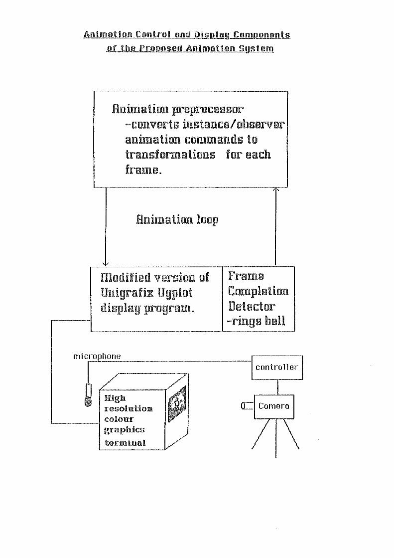
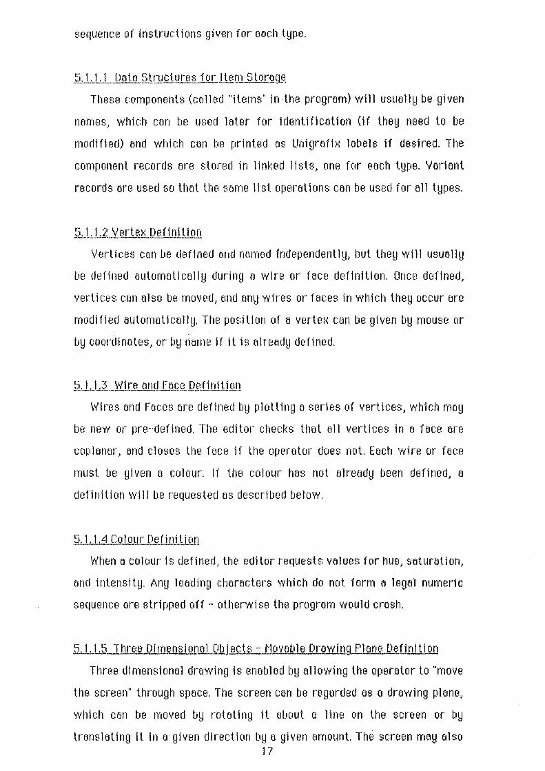
Animation Control and DisnJay Comf!onents
_of._llte_PrODOSed Alllm!tllon S!Jili.ID.
Hnimation preprocessor -converts instance/observer animation commands to trans:fonnations for each frame.
·- ------···---------~·-----·-,.---!
Hnima tion loop
modified version of Unigrafix U gplot display prograrn.
Frame Completion Detector -rings bell ______________ __,.___ ____ __,
micro~e =---~ High
resolution a= Comen:. colour ...__ ___ ~ graphics terminal 7

6. Ani motion Control ond Di spJJ!y
6.1 Command file lntenJretation and ContrQL:_Anime~tion PreP-rocessor
The frames ore displayed using o two-stage process. The first steJge,
celllE!CI the Animation Preprocessor, reads the Animation Command File and
extracts ti1E1 non-standard stetements. From these 1t calculates the
stemderd object instence stotements ond the ugplot display perameters for
the frornes. The 1-\ni meti on preprocessor then creates e stondord Uni grafi x
scene description for each frame, ond pipes these descriptions to ugplot.
6.2 Rem~ for Sc:q~~oroti ngJl:lf..1illltl1Gti on E'n!.Rrocessor
It hod been hoped thot repee.ted i scene f1Je interpretetion could be
ovoi(Jed by including the onimotlon preprocessor in o modified version of
ugplot, ond eltering the tronsformotions in the ugplot dt1ta structures
before each frome. Unfortunotely 1 these deto structures Bre destroyed t:~s
the scene is processed, m1d retaining them would entelil o mojor revision
of the program. Implementing the onimotion program os two seporote
processes simplifies t11e operation, and in fact tbe time required for
processing the scene ffl es is expected to be negl i gi b 1 e compared with the
hidden line (:lliminaUon emd terminal output times.
G.3 .camera Control - t'lodific~_tion of UgQlot
The ugplot progrom requires o small modificotion for the animation
system. When the i mege has been c11 sp 1 eyed, it is necessary to send el
signed to the camera control. It wos decided that the eosiest wey to
provide the signed would be to send o bell signeJ1 to the terminol, and
detect the tone with tl microphone. The tone is sent during the ugplot
wrap-up procedure~ ond the program then waits briefly while the freme is
filmed.
This method was chosen because it would otherwise be difficult to
pro vi de a termi na 1 contra 1 si gne1l which could be "topped" and would be
guaremteed to be unambiguous for all types of grephics terminal. ldeelly, a
separote line would be used to provide ~;uch e signal~ but this would be
rother wasteful if o limited nmnber of ports were ovoiloble. 21

6.4 Advantages emd Disadvantages of Film es o Transfer Medium
Using a camera emd e termi no l mey ot first oppeer El primitive method
of transfer. There ere, however, eJ number of advemtages to this approach.
Primer1ly, it makes use of existing equipment, end requires minimal
hardwere development. Another edventt:~ge is thEJt cornerEJ techniques cen
be used to modify thE! image. Stoircasing can be redllced with the help of a
soft -focus lens, end various effects such as irnege "glow" con be produced
by filten; end exposure edjustments. Many commercial graphics producers
use this method of fi 1 rn trensf er for the st:~me reosons.
The rnoin dise~dvemtege is e slight deley between the recording and the
viewing of the clip. Films con be processed quickly (less them on hour) ot
TVNZ's laboratories, but there will be a certain inconvenience in having to
trevel between the terrninel sitE! end the rnain offices to view the results.
6.5 Test Clips- Frome SkiQ.Qing
For developrnent work, it would be em odvontoge to provide on option in
the animation preprocessor which displayed only o portion of the fremes.
It might disploy the key frornes only, or display every nth freJme where n
WCIS an input parameter. This would ollow the designer to view the overelll
effect of the sequence without hoving to Wtlit for the full number of
fnm1es.
22

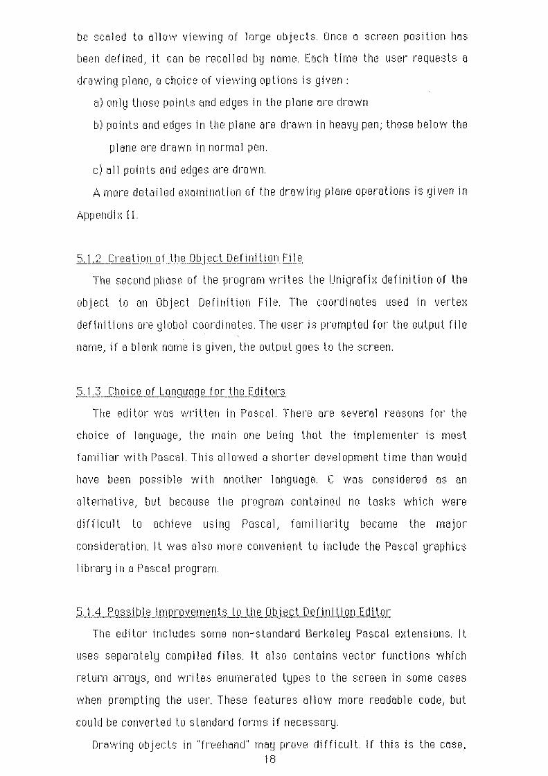
3D ..:Vii re-rr·am_~ Demorwt_r·at 1 or) Obj..f!Ch~ Created U:,:;i ng_ !.1!1!J!l!j ect Oefi nit t on __ (J.fU.or
1. Three views of a (battered?) shopping basket. The first two views were recorded from the object definition editor, and the side view was drovvn by Unfgrafi>< from the resulting object definition f11e.
2. Tt·ds teepot (I) 1s not expected to win any design awerds. It was drewn by Un1graf1x e~nd defined by the Object Definition Editor. The 11d is defined as o solfd face.
3. These two sets of lettering are des1gned to demostrate the Un1grafix perspective projection. The foreground lettering wt:.~s trt:.~ced over the background lettering 1n a parallel plane.

L. Results
At this t;toge of development, thene ere few concrete results to be
documented.
However .. Uw ori~11nal purpose of t11e project - to explore possible
methods of providing Television New Zealand with more sophisticated
computer graphics- hfls been refllized, tmd the result is this report.
A prototype emimerlion system has been designed, Emd is in the process
of being implemented. Those parts of the system which heve been
implemented, nomely the two Unigrafix Terminal lnterfoces ond the Object
Definition Editor, are working sotisfoctorily.
Some examples of tl'l8 work of Object Definition Edltor oro shown
opposite. They dernonstrete the operfltor's total leek of ortistic eJbility ond
the lirnitt:~tions of the l"lt:~cintosh disploy rflther thfln any strengths or
weaknesses of the program, but in producing the objects it wos noted that
the exte·nsions recommended eoriier in the poper would hove been voluoble.
It would be difficult to predict the time which a grophic ortist would
require to drow fl given object. The irneges shown opposite were produced
in en evening, but with the rec:ornrnended extensions and some practice
this tirne could be reduced considerablhl· Howevet~, it should be noted that
the definition of e~ feirly simple three dirnensionel object- suct1 a styllsed
te I evi si on picture tube - can take more than an hour using the Bosch
FGS-4000 editors.
8. Evoluotion
There ore no apperent reasons to suggest lhet the onimotion system
described would not work. Whether it would be useful for the required
purpose con only be tested by cornpleting the implementation of the
prototype.
Tl'lere ere t:1 number of fectors which could work egainst the success of
the project:
1. It might not be possible for TVNZ to obtein o graphics terrnint:~l with
sufficiently high resolution.
2. Permanent occess to o computer which could run Unigrofix or a 23

si rnil or system might be difficult to ornmge.
3. The editors might require somE! revision once they heve been tested
by the graphic artist~;. This would be a setback/ rather than a ceuse
of failure.
4. The development time for grephics clips might not bE! cost-effective.
5. The fretrtE! generation ond display times might be unoccep.tobly slow.
Figures from [ 13} indicate that o complex image (opprox. 1000 faces)
ce~n be processed in less than one minute of CPU time. This should
allow o 15s clip at 24 frames pE!r second to be processed overnight if
usage is 1 ow, ond it is therefore hoped thet di sp 1 ay ti rnes wi 11 be
fosl enough.
Given thot the commercial compe:mies are currently struggling to meet
the demond for sophisticated computer grophlcsl end thet mechines such
as the Bosch FGS-4000 hove considere'Jbly greater copebilities the111 the
proposed system/ the animation system is unlikely to be in competition
with existing graplli c:s supp 1 i ers. If tl1e project i ~: successful/ however/ it
mey allow the use of computer gropllics in television epplicf:ltions which
would other'lvise be unable to efford them.

Bib I i.Qgruuhy A. T echni ceJJ!ltrodttr.:..ti9.ns t_Q.. CpJn~.r.!AJer Gre~1hi c~
1. Scott, ... I.E.
2. Rogers~ D.F Adams, --I.A.
3. V/ein, M. Evens, K. Te:mnerJ'.
4. (Verious)
5. Swain, R.
6. Egon, ... I.T. Hart, --1. ~1ec:Elroy, R.D.
7. Joshi, R.R. Arunochal em, H.
8. Foley, ,J.D. ¥/enner, P.A.
9. Cohn, D.U. Ven, A.C.
1 0. Ozsoy, T. Ochs, --I.B.
l.ntrog_qcli~!ft to lntertJctive ComQuler Grt1pl1ics --lohn Wiley and Sons, 1982.
t'lathernoli cal Elements for COI:rli:JUler GraQ!·Ii cs McGraw-Hill, 1976.
"Tutoriel Notes: Introduction to Computer Grephics" Proceedi o.gs of the DEC Us~_rs' Socj ~tyl Coneda 1983 pp95 -185
"NICOGf\APH '82: Keynote Speeches emd Addresses" AC:M I SIGGRAPH- ComQuter GroQhics 17 I 2 (Mey 198:~) pp 91 - 93
"Animation: At the leading edge?" p.udio Vjsuol August 1984 pp31 - 33
"Anel ~lsi ng ond Comparing the Perf ormonce of Two Real-time Playback Systems"
Conwuters and GraQhics 8 I 1 pp67 - 79
"GRASP- A 3D Graphics System for Pascal Users" Conwuters end GroQhics 8 I 1 pp93 - 102
"The George V/oshington University CORE System Implementation"
ACt1/ SIGGRAPH - Com~tuter Gra~!hics 15 I 3 (August 1981 ) pp 123 - 13 1
"A Device Independent Network Graphics System" AC;tlL SJ.§~RAPH - ComQuter GroQbics
17 I 3 ('"luly 1983)
"Lehigh University's VS-11 :~D Color Graphics Package"
Proc:eedi ng.§_ of Ut!!J2EC L!5!.8r~_Socj ely~ U.S.A Spring 1983 pp 91 - 93
25

11. Sequin~ C.H. Segel~ ~1.
Wens1ey1 P.
UNIGISAFIX 2.0 User's Memuol ond Tutorial Universit~l of Ca1ifornio~ Berkeley December 1983
12. Sequin/ C.H. (Eel.) Creo_!ive G~ometric Modelling with UNI!,JRAFIX
13. Sequin~ C.H. StreJuss~ P.S.
14.
15. Anton/ H.
Uni 'v'E!rsity of Co 1 if orni o, Berke 1 ey December 1983
"UNIGRAFIX" A.C.t'l. I.E.E.E. 2pttlJ)s!sign Automation Conference
-Proceeding.§. 1983 pp 374- 381
GrHfin Termin~l User MenueJ1 t'leloreseerch Inc.
E1emento_ry ~ioeor A1gebro 2nd Edition ·-,John Wiley ond Sons/ 19Tl.
26

Atmendix I
Extensiot)s to U:w _Unigrofix 1anglwge (cw the Ani motion Col)troJ Flle
The additions to the lemguoge ere expressed below in the format of the
Forma 1 Syntex Definition given in eppendi x C of the Uni grafi x User's t··tonua 1
end TutoriCJ1 [ 11]. The extensions ere designed to fit the structure of the
origint~1 language, so thet the Animation Control File remains reodable ond
con be edited os eJ text file if necessewy.
ugFi1e == {command}
commend == pri mCornrnand I defi nit i onCornmand semi
primCornrnond == verte)~Comrnond I wireCornmand I faceCornrnemd I 1 i ghtCornrnemd I co 1 ourcornrnond I i nstenceCommend I erreyComrnend I inc1udeCommand I comment I ernptyCornmand
verte><Commemd == v i d 3dVector
wireCornrnand == w lid] ( id id {1d}) {( id id )} [colorld]
focclCornrnend == f lid] ( id id id {id}) {( id id id )} [colorld]
[ <11ornogVector >]
1ightCornmend =~ 1 [id] intensity !3dVector !number])
colorCommend :::::: c id number [number !number [number] 1 1
definitionCornmend == defStertCommand serni {prirnCornmend} defEndCornrnend
defSlertCommand == tlef (lefnerne
defEndCommand == end
instenceCommand == i [id] ( defnerne [t.rensfonnationsl)
arreyCommand == e [id) ( defnarne [transformations)) integer [t.rensformations]
includeCornrnend ==include filename
27

comment == ( {cormnentChor} !comment] {commentChor} }
emptyCornmond ==
sem1 == ;
i d == stri ngvar
colorld == stringvar
defname == stringvar
stringvar ::= IBI IBr s!Jo;psi§IJ {Jet tar I o'J~41it I ti!Jderscore I sllarpsipfl I ptlriod I colon }
illum == number
hornog\lector == 3dVector number
3dVector == number number number
transformations== -sx nurnber I -sy number I -sz number I -sa number I -rx number I -ry number I -rz number I -tx number I -ty number I -tz number I -mx I -my I -mz I -rna .I -113 < 1 to 9 numbers> I -M4 < 1 to 9 numbers>
number== fntBgBr I reo/
comment Char == eny cllb-r&ct ar except { and )
pri mCornrnand == pri mcornrnand I vi ewportCornrnand I key I nstCommand
viewportComrnand == o frameCount viewOption {viewOption} deviceiD projection
( keyVi ewXf orrn {keyVi ewXf orm} keyVi ewXf orm )
ke~11 nstComrnand == k [ i d] ( defnarne keyXf orm {keyXf orm} keyXf orm )
frameCount == ill t B!j'ttr
viewOption == -se I -sf I -sa I -obI -hn I -hb I -hoI -lv I -vz number I -vo number
deviceiD -·dv I -dw I -tim I - do I -dx I -dr I -di I -d7 I -dg
2Ei

projection :::: ·-·ep I -ed
keyViewXform =:: I frem1emHn e 3dVE:Jctor c 3dVector I r number 1 J
ke~!Xforrn ::::: ( fnnnenurn t 3dVector I r 3dVector 1 [ s number] J
frf1rnenum ::::: i;;teger
No!_~-~
1. There rnust be exactly one viewport cornmemd in em Animation Control
File.
2. The components of a key frame viewport transformation construct are
(from left to rlgl·1t):
·· the number of the frame
·-the e~1e direction (for parallel projections) or eye position
(for perspective proJections)
- the view centre (centred screen point) of the scene
- the rotation of the scene (default is y-e~xis vertical)
3. Tl'le components of a key frame instance tnmsforrnatlon construct are
(from left to right) :
- the number of the frame
- the trans 1 ali on of the i nstonce from the defl nit ion
-· the (x~y,z) oxi s rototi on components
·· the scole fector
4. Animation is performed for up to fron;ecotltlt fremes. Any key frame
with o higher freJrne number will be ignored. In a· key frome
tronsforrnotion list~ the following rules must be obeyed:
-all key frames must be given in order of frame number
- the number of the first key frome must be equal to 1
- the number of the 1 ast l<ey fro me must be greater than or equo 1
to fromecotll?t.
29

Not_ts CtJLthe 3-D f eJcil i ties in the Dtrj eel Defi ni U on Editor
The notes in this oppendix ere not intended to tre an introduction to the
mothernatics of three dimensionol transformations, but rother es a brief
description of the methods used for the drawing p 1 ene trensf ormBti ons in
the Otr j ect Definition Editor. For deteli 1 s of the methods used in computer
gre~phics, refer to Rogers end Aderns [2]. For the methemetictll basis of
these methods, end the proof of their velidity, refer to Anton [ 15].
The three-dirnensi one 1 feci 1 i ties of the editor necessitelte e
considerable mnount of vectot- metnipule~tion. Eech vertex record holds two
vectors. One represents the position (x, y, z) of the vector re l e~ti ve to a
gl obo 1 coordi note system, end the other gives its position (l<, y, depth)
relative to the screen.
Eech drawing plene record holds two 4x4 rnotrices for tremsforming
· bet ween the coordi ne~te systerns. When e new vert e)< is defined in terms of
its screen coordinates x, y, depU-1 (i.e. try mouse), its global coordinates are
calculated try rnultiplying the augmented vector§. = (x, y, depth, 1) try the
screen->glotral coordinate transformation matrix M:s:w· Similarly, when a
new plane is drawn, the screen positions are calculated by multiplying the
augmented global vector ':f{ by the globe~l->screen coordinate
trensf ormation matrix Mws·
In the initial dravving plane, the screen coordinates are equal to the
global coordinates. The coordinate transformation matrices Msw tmd Mvts
for the initial plane record are therefore identity matrices.
A new dren·ving plene con be cJefined by a rotation about an axis in the
current plane, a translation from U1e current plane position, or a scaling of
the current plane. If a combinaUon of transformations is required, u·,ey are
performed sequentially in the at1ove order.
Each transformation is represented es a 4x4 matrix, Tn. For each plane,
r1 is given trw rnultipl"inQ the previous M . by tl'le given Tn, and M,,,5
is S'W' .._ ;:I '" S\1' ...-
given t:'~l multipl~linD tho in\,er~:e of Tn tl!d the previous Mws. (Note tl1at the
30

order 1s different in the two cases, since matrix multiplication is not
commutative.) t1sw is therefore given b~l a series of transformations:
f\w ::: T1 )< T2 ><: T3 X T4 x ...................... x Tn
SirnilBrl~L tlv.··s is given by Uw sories of transformetions:
Mws :: Tn-t X ................... x T4- 1 X T3-1 X 12-1 X 11··1
4x4 matrices e:we required to give e single representetion of oil
tronsfonnotions which cen occur in the system. A 3x3 matrix is sufficient I
to represent orthogonal transfonnt'ltions (rotation, scf.lling, shearing, ond
rE!flection) but a 4x4 motrix is required to inclucJe translation of the origin
and perspective projections. (At present, the first three rows of the finol
column will olwoys be zero, because the editor uses only pore.llel
projection. If perspective projections ore odded to the system, relatively
few changes wi 11 be required to occomrnodo le them).
or-iginally, tronsletion WfJS represented by a seporote vector. It was
felt, however, that the Qf.lin in efficiency which this mey have allowed (by
ell owing the use of a 3x3 transformation rnetrix) was out weighed by the
exlrf.l complexity required in the progrt:~rn.
Representing the individual plt:~ne transformt~Uons by mt~trices ( 1n )
requires a greeter number of rnultiplic:Ellions them direct rnultipllcation of
t11e affected entries of tt1e coordinate transformation matrices ( M~P« and
t1\'ts ). Since definition of a new plane is relatively rare, however~ program
simplicity was again considered the more important factor.
31

The plane trt~nsformation matrix for translation tty (x, y, z) find the
inverse tronsfonnotlon nwtrix ore shown below:
1 0 0 0 -I 1 0 0 0 ln= 0 1 0 0 Tn = 0 1 0 0
0 0 1 0 0 0 1 0 X y z 1 -x -y -z 1
The matrices for sealing by factors are :
1 0 0 0 ··1 1 0 0 0 ln= 0 1 0 0 Tn = 0 1 0 0
0 0 1 0 0 0 1 0 0 0 0 s 0 0 0 1 s
Rotation about an arbitrary en<is involves a translation and an
orthogonal rotation. The simplest way to calculate the effect of such a
rotation is to transform to e coordinate system which hes its origin et en
arbitnu-y point on the axis of rotation, perform the rotation, and then
transform bacl< to the original coordinate system. An algorithm which
simulates this procedure is given in [2L and has been adapted for use in
the editor.
32