angular heads - etusivu · • spiral-toothed bevel gear box with new tooth geometry and surface...
TRANSCRIPT

Angular Heads

„For more than 50 years the name ROMAI has stood for
the highest precision and process reliability in machining.
The next generation begins today.
We have succeeded to further improve the performance of our
angular heads. More torque for the same size and at consistent
acquisition prices. Both for standard and special functions.
Just what you are used to from ROMAI.“
Tradition in Perfection.

Established Rotational Mechanics
3
OVERVIEW
Rationalization
NXT Generation
Versions Forms
Structure Angular Head
Overview Drives / Outputs
Available Machine Interfaces
Machine Connection Examples
Available Tool Holding Systems (Outputs)
Specifications Form S
Form S-2
Form W
Form G
Form F
Form D
Special Designs
4
5
6
7
8
10
11
12
16
17
18
19
20
22
23
Page
Page
Page
Page
Page
Page
Page
Page
Page
Page
Page
Page
Page
Page
Page

4
RATIONALIZATION
Established Rotational Mechanics
Angular Heads by ROMAI
• Minimizing the number of tool clampings
• Reducing the machining time
• Simplifying elaborate machining processes
• Exact reproduction of production steps
• Enhancing process reliability
• Reduction of machine downtime periods
• Machining of otherwise inaccessible parts of the work piece (internal machining)
• Cutting costs through complete processing

• Spiral-toothed bevel gear box with new tooth geometry
and surface treatments
• 30-50 % more torque
• For all machines
• For all tool systems
• Drilling, reaming, countersinking, threading, milling,
and grinding
• Roughing and finishing up to 6,000 Nm
• With torque support (DMST), 3- or 4-point support,
mechanic/hydraulic clamping or flanged
• Internal and/or external coolant supply with pressures
of up to 70 bar (use-oriented of up to 140 bar, more
on request)
• Transmissions and reductions of up to 40,000 rpm
individually realizable
The next Generation.
5
NXT GENERATION

Form
S
Angular Head 90° with offset output
(slim shape for special application)
For special machining tasks with strong geometric con-
straints. Offset output to maximize the usable tool length.
Internal coolant optional. (Page 19)
Form
G
Angular Head 0°-90° with fine adjustment
For machining tasks in changing, angular position. Because
of the variable adjustment, any angle between 0°-90°
(process reliable) can be set. Up to 110° optional. Internal
coolant standard, can be omitted optionally. (Page 22)
Form
D
Angular Head with fixed angle (for special application)
For special machining tasks in fixed angular position. Inter-
nal coolant standard, can be omitted optionally. (Page 20)
Form
F
Angular Head 90°
For machining tasks without geometric constraints. Internal
coolant optional. (Page 16)
Form
S-2Angular Head 90° with bilateral output
For machining tasks in the opposite direction or with diffe-
rent machining tools. Internal coolant optional. (Page 17)
Form
WAngular Head 90° with offset output
For machining tasks with geometric constraints. Set-back
output to maximize the usable tool length. Internal coolant
standard, can be omitted optionally. (Page 18)
a
6
VERSIONS

Established Rotational Mechanics
Torque support
(DMST)
Locking bush
Locking disc
Connecting plate
Rotation (360°)
Housing
Output
(tool holding system)
Driving shank
(machine spindle)
Locking disc / locking bush
Exact locking of the angular head for the
automatic tool change. Exact fitting into the
magazine and therefore process reliability is
guaranteed.
Connecting plate
Support of the angular head against tilting
during machining.
Rotation (360°)
All ROMAI standard angular heads can be
manually turned around 360°. Fixation is with
clamp screws. Hirth coupling is optional.
Driving shank
Fitting of the angular head in the machine. All
machine interfaces can be realized, e.g. HSK,
SK, Capto, MAS-BT, CAT, and many more
(see page 10).
Torque support (DMST)
Locates the angular head at the machine
spindle and secures it against tilting caused by
machining forces. Because of the variety and
the differences in machine tools, the torque
support is usually implemented machine-
specific, and we adapt it to the individual
machine type.
Output (tool holding system)
Clamping of the cutting tool for machining.
All tool holding systems can be realized, e.g.
collets, WFB, HSK, SK, CAT, and many more
(see page 12).
7
STRUCTURE

MAS-BT
KM Kennametal™
Tool shank (SK)
Hollow taper shank (HSK)
Coromant Capto®
CAT
Special drives
DRIVES
Established Rotational Mechanics
8

Hydro clamp chuck
ABS® KOMET® (Licence)
Coromant Capto®
Cutter spindle
Hollow taper shank (HSK)
Collets ER–Zeta
(Zeta® Zollmann System)
Tool shank (SK)
Weldon & Whistle Notch
WFB
HYDRO-FIX®
KM Kennametal™
(Licence)
Collets ER
(Regofix System)
Collets ER-A
(Regofix System)
Collets ER–Zeta
(Zeta® Zollmann System)Special outputs
OUTPUTS
9

Interface Available sizes
CAT 30
CAT 40
CAT 45
CAT 50
CAT 60
C3
C4
C5
C6
C8
C8X
C10
32
40
50
63
80
80X
100
CAT
Form AD/B
Coromant Capto®
ISO 26623
BT 30
BT 35
BT 40
BT 45
BT 50
BT 55
BT 60
MAS-BT
JIS B 6339
Form AD/B
SK 30
SK 40
SK 45
SK 50
SK 60
Tool shank (SK)
DIN 69871 / ISO 7388
Form AD/B
KM 40
KM 50
KM 63
KM 80
KM 100
KM Kennametal™
HSK 25
HSK 32
HSK 40
HSK 50
HSK 63
HSK 80
HSK 100
HSK 125
HSK 160
Hollow taper shank (HSK)
DIN 69893 / ISO 12164
Form A & C
MACHINE INTERFACES
10
Non-specified interfaces are special versions and are available on request.
Talk to us about it!

DMST + 3-point-support Mechanic / hydraulic clamping
Connector Block (Stop-Block)
Machine connections from ROMAI are suitable for adapting
to the machining center through the customer, and are
standardized to ISO 9524 in their design. On request the
connector block will be prepared by ROMAI. Otherwise the
customer has the opportunity to place the pattern of drilling
by himself.
Please also refer to the current version of the operation
instruction manual on www.romai.com .
Machine Connection Examples
EXAMPLES / CONNECTOR BLOCK
11
Torque support (DMST) DMST + 4-point-support
30
Slot for torque support46
82
65
32,5°
32,5°
65
(20,
5)9,
5
R13
0
R90
18
All dimensions in [mm].

Interface Available sizes
ABS 20
ABS 25
ABS 32
ABS 40
ABS 50
ABS 63
ABS 80
ABS 100
ABS 125
C3
C4
C5
C6
C8
C8X
C10
32
40
50
63
80
80X
100
ABS® KOMET® (Lizenz)
Coromant Capto®
ISO 26623
Ø 6
Ø 8
Ø 10
Ø 12
Ø 14
Ø 16
Ø 20
Ø 25
Ø 32
Ø 40
Ø 50
Hydro clamp chuck
HSK 25
HSK 32
HSK 40
HSK 50
HSK 63
HSK 80
HSK 100
HSK 125
HSK 160
Hollow taper shank (HSK)
DIN 69893 / ISO 12164
Form A & C
Ø 10
Ø 13
Ø 16
Ø 22
Ø 25
Ø 27
Ø 32
Ø 40
Ø 50
Ø 60
Ø 80
Cutter spindle
Not specified interfaces are special versions and available on request.
Talk to us about it!
TOOL HOLDING SYSTEMS (OUTPUTS)
12

Established Rotational Mechanics
Interface Available sizes
NBC- 10/ 16- 40
NBC- 12/ 16- 40
NBC- 16/ 20- 46
NBC- 20/ 25- 46
NBC- 25/ 32- 50
NBC- 32/ 40- 55
NBC- 40/ 50- 60
NBC- 42/ 50- 62
NBC- 42/ 60- 62
NBC- 50/ 60- 70
NBC- 60/ 80- 100
NBC- 80/ 100- 120
NBC- 100/ 120- 140
KM 25
KM 32
KM 40
KM 50
KM 63
KM 80
KM 100
HYDRO-FIX®
KM Kennametal™
(Licence)
ER 8 :
ER 11 :
ER 16 :
ER 20 :
ER 25 :
ER 32 :
ER 40 :
ER 50 :
1- 5 mm
1- 7 mm
1- 10 mm
1- 13 mm
1- 16 mm
2- 20 mm
2- 30 mm
4- 34 mm
Collets ERST–Zeta
(Zeta® Zollmann System)
DIN 6388 / DIN 6499 /
ISO 15488
ER 8 :
ER 11 :
ER 16 :
ER 20 :
ER 25 :
ER 32 :
ER 40 :
ER 50 :
1- 5 mm
1- 7 mm
1- 10 mm
1- 13 mm
1- 16 mm
2- 20 mm
2- 30 mm
4- 34 mm
Collets
(Regofix System)
DIN 6499 / ISO 15488
TOOL HOLDING SYSTEMS (OUTPUTS)
13
ER ER-A
ER ER-A

Interface Available sizes
SK 30
SK 40
SK 45
SK 50
SK 60
Ø 6
Ø 8
Ø 10
Ø 12
Ø 14
Ø 16
Ø 18
Ø 20
Ø 25
Ø 32
Ø 40
Tool shank (SK)
Weldon & Whistle Notch
WFB 20
WFB 24
WFB 32
WFB 40
WFB 50
WFB
Non-specified interfaces are special versions and are available on request.
Talk to us about it!
Established Rotational Mechanics
TOOL HOLDING SYSTEMS (OUTPUTS)
14

15
S 5
S 6
S 7
S 10
S 20
S 30
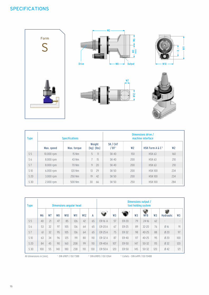
TypeDimensions output /tool holding systemDimensions angular head
47
97
95
96
90
140
W8
21
32
32
34
45
55
W7
All dimensions in [mm]. 1 DIN 69871 / ISO 7388 3 Collets – DIN 6499 / ISO 154882 DIN 69893 / ISO 12164
42
64
64
80
99
110
W12
40
53
61
63
84
100
W6
85
105
105
125
160
180
W10
126
136
136
191
208
238
W11
65
65
65
110
110
130
A
24-16
32-20
40-25
40-25
50-32
50-32
W3
-
91
97
100
120
121
W3
79
89
98
117
147
145
W3
57
67
75
87
107
120
ER-16 A
ER-20 A
ER-25 A
ER-32 A
ER-40 A
ER-50 A
ER-20
ER-25
ER-32
ER-40
ER-50
ER-50
W3
62
76
88
95
115
120
S 5
S 6
S 7
S 10
S 20
S 30
HSK 63
HSK 63
HSK 63
HSK 100
HSK 100
HSK 100
160
210
210
234
234
284
Type SpecificationsDimensions drive /machine interface
Max. torque
150
200
200
200
200
250
Max. speed
SK 40
SK 40
SK 40
SK 50
SK 50
SK 50
SK / CAT/ BT 1 W2 HSK Form A & C 2 W2
10.000 rpm
8.000 rpm
8.000 rpm
6.000 rpm
3.000 rpm
2.000 rpm
15 Nm
43 Nm
70 Nm
120 Nm
250 Nm
500 Nm
Weight[kg] [lbs]
5
7
9
13
19
30
11
15
20
29
42
66
-
Ø 16
Ø 20
Ø 20
Ø 32
Ø 42
SPECIFICATIONS
16
Form
SW10
A W11
W2
W8
W3
(max
)
W7
W12
W6
Drive Output
HydraulicWFB3 3

S 5 -2
S 6 -2
S 7 -2
S 10 -2
S 20 -2
S 30 -2
S 5 -2
S 6 -2
S 7 -2
S 10 -2
S 20 -2
S 30 -2
HSK 63
HSK 63
HSK 63
HSK 100
HSK 100
HSK 100
160
210
210
234
234
284
Type SpecificationsDimensions drive /machine interface
Max. torque
150
200
200
200
200
250
Max. speed
SK 40
SK 40
SK 40
SK 50
SK 50
SK 50
SK / CAT/ BT 1 W2 HSK Form A & C 2 W2
15 Nm
43 Nm
70 Nm
120 Nm
250 Nm
500 Nm
Weight[kg] [lbs]
TypeDimensions output /tool holding systemDimensions angular head
47
97
95
96
90
140
W8
21
32
32
34
45
55
W7
42
64
64
80
99
110
W12
85
105
105
125
160
180
W10
126
136
136
191
208
238
W11
65
65
65
110
110
130
A
24-16
32-20
40-25
40-25
50-32
50-32
W3
-
91
97
100
120
121
W3
79
89
98
117
147
145
W3
57
67
75
87
107
120
W3
62
76
88
95
115
120
-
Ø 16
Ø 20
Ø 20
Ø 32
Ø 42
Established Rotational Mechanics
SPECIFICATIONS
17
W10
A
W11
W2
W8
W3
(max
)W
3(m
ax)
W7
W12
Drive Output 1
Output 2
Form
S-2
ER-16 A
ER-20 A
ER-25 A
ER-32 A
ER-40 A
ER-50 A
ER-20
ER-25
ER-32
ER-40
ER-50
ER-50
10.000 rpm
8.000 rpm
8.000 rpm
6.000 rpm
3.000 rpm
2.000 rpm
HydraulicWFB3 3
5
7
9
13
19
30
11
15
20
29
42
66

All dimensions in [mm] 1 DIN 69871 / ISO 7388 3 Collets – DIN 6499 / ISO 15488 4 With internal coolant.2 DIN 69893 / ISO 12164
HSK 63
HSK 63
HSK 63
HSK 100
HSK 100
HSK 100
190
230
255
279
294
314
Type SpecificationsDimensions drive /machine interface
Max. torque
180
220
235
245
260
280
Max. speed
SK 40
SK 40
SK 40
SK 50
SK 50
SK 50
Weight[kg] [lbs]
SK / CAT/ BT 1 W2 HSK Form A & C 2 W2
15 Nm
43 Nm
70 Nm
120 Nm
250 Nm
500 Nm
5
8
10
17
24
36
W 5
W 6
W 7
W 10
W 20
W 30
TypeDimensions output /tool holding systemDimensions angular head
79
119
96
141
150
170
W8
80
98
109
116
150
175
W6 (IK) 4
26
30
37
45
50
60
W7
55
70
70
90
110
140
W12
63
75
84
100
125
150
W6
85
105
105
125
160
180
W10
126
136
136
191
208
238
W11
65
65
65
110
110
130
A
24-16
32-20
40-25
40-25
50-32
50-32
W3
-
44
47
41
43
36
W3
39
42
48
58
70
60
W3
17
20
25
28
30
35
W3
22
29
38
36
38
35
-
Ø 16
Ø 20
Ø 20
Ø 32
Ø 42
W 5
W 6
W 7
W 10
W 20
W 30
SPECIFICATIONS
18
W10
A
W11
W2
W8Drive
W7
W12
W6
W3
(max
)
W6
(IK)
Output
Form
W
ER-16 A
ER-20 A
ER-25 A
ER-32 A
ER-40 A
ER-50 A
ER-20
ER-25
ER-32
ER-40
ER-50
ER-50
10.000 rpm
8.000 rpm
8.000 rpm
6.000 rpm
3.000 rpm
2.000 rpm
HydraulicWFB3 3
11
18
22
37
53
79

G 5
G 6
G 7
G 10
G 20
G 30
TypeDimensions output /tool holding systemDimensions angular head
129
139
149
186
221
266
W8
67
84
90
123
138
155
W6 (IK) 4
21
25
32
40
45
55
W7
45
55
65
80
99
119
W12
50
70
76
90
110
130
W13
42
56
66
98
113
130
W6
85
105
105
125
160
180
W10
95
95
120
154
154
150
W9
126
136
136
191
208
238
W11
65
65
65
110
110
130
A
24-16
32-20
40-25
40-25
50-32
50-32
W3
-
36
34
9
9
6
W3
41
34
35
26
36
30
W3
19
12
12
-4
-4
5
W3
24
21
35
4
4
5
G 5
G 6
G 7
G 10
G 20
G 30
HSK 63
HSK 63
HSK 63
HSK 100
HSK 100
HSK 100
240
250
260
324
364
414
Type SpecificationsDimensions drive /machine interface
Max. torque
230
240
250
290
330
380
Max. speed
SK 40
SK 40
SK 40
SK 50
SK 50
SK 50
SK / CAT/ BT 1 W2 HSK Form A & C 2 W2
15 Nm
43 Nm
70 Nm
120 Nm
250 Nm
500 Nm
Weight[kg] [lbs]
5
7
8
15
22
34
-
Ø 16
Ø 20
Ø 20
Ø 32
Ø 42
Established Rotational Mechanics
SPECIFICATIONS
19
W10
A
W11
W2
W8W7
DriveOutput
W6
W3
(max
)
W6
(IK)
W12
W13
W9
Form
G
ER-16 A
ER-20 A
ER-25 A
ER-32 A
ER-40 A
ER-50 A
ER-20
ER-25
ER-32
ER-40
ER-50
ER-50
10.000 rpm
8.000 rpm
8.000 rpm
6.000 rpm
3.000 rpm
2.000 rpm
WFB Hydraulic3 3
11
15
18
33
49
75

F 5
F 6
F 7
F 10
F 20
F 30
TypeDimensions output /tool holding system
24-16
32-20
40-25
40-25
50-32
50-32
Winkela
30°
45°
60°
30°
45°
60°
30°
45°
60°
30°
45°
60°
30°
45°
60°
30°
45°
60°
8
58
39
7
27
45
7
30
50
7
34
56
7
45
75
8
55
95
W5
66
90
88
75
90
98
81
95
101
90
105
113
107
120
125
130
140
145
W6
107
99
87
119
109
95
125
114
99
149
137
118
205
190
165
256
236
206
W8
19
41
58
18
43
64
19
46
70
22
55
82
27
73
110
21
73
117
W5
66
90
88
75
90
98
81
95
101
90
105
113
107
120
125
130
140
145
W6
126
115
98
138
125
106
145
130
111
175
158
133
240
218
185
278
254
219
W8
11
29
43
12
33
53
14
39
61
11
40
63
11
51
82
8
55
95
W5
66
90
88
75
90
98
81
95
101
90
105
113
107
120
125
130
140
145
W6
111
103
90
127
115
100
136
123
106
156
143
122
212
196
169
256
236
206
W8
-
19
44
66
18
46
69
14
43
67
14
54
86
9
56
96
W5
-
75
90
98
81
95
101
90
105
113
107
120
125
130
140
145
W6
-
140
126
107
144
130
110
160
146
125
216
199
172
257
237
207
W8
All dimensions in [mm]. 1 DIN 69871 / ISO 7388 3 Collets – DIN 6499 / ISO 154882 DIN 69893 / ISO 12164
ER-16 A
ER-20 A
ER-25 A
ER-32 A
ER-40 A
ER-50 A
ER-20
ER-25
ER-32
ER-40
ER-50
ER-50
-
Ø 16
Ø 20
Ø 20
Ø 32
Ø 42
SPECIFICATIONS
20
W10
A
W11
W7
W8(max)
Drive Output
W5
(max
)
W2
W12
W6
a
Form
F
a
WFB Hydraulic3 3

F 5
F 6
F 7
F 10
F 20
F 30
208
218
200
210
188
198
220
230
210
220
196
206
226
236
215
225
200
210
262
296
250
284
231
265
315
349
300
334
275
309
370
404
350
384
320
354
21
32
32
34
45
55
85
105
105
125
160
180
126
136
136
191
208
238
42
64
64
80
99
110
65
65
65
110
110
130
10.000 rpm
8.000 rpm
8.000 rpm
6.000 rpm
3..000 rpm
2.000 rpm
15 Nm
43 Nm
70 Nm
120 Nm
250 Nm
500 Nm
227
237
216
226
199
209
239
249
226
236
207
217
246
256
231
241
212
222
288
322
271
305
246
280
350
384
328
362
295
329
392
426
368
402
333
367
212
222
204
214
191
201
228
238
216
226
201
211
237
247
224
234
207
217
269
303
256
290
235
269
322
356
306
340
279
313
370
404
350
384
320
354
-
-
-
-
-
-
241
251
227
237
208
218
245
255
231
241
211
221
273
307
259
293
238
272
326
360
309
343
282
316
371
405
351
385
321
355
SK 40
HSK 63
SK 40
HSK 63
SK 40
HSK 63
SK 40
HSK 63
SK 40
HSK 63
SK 40
HSK 63
SK 40
HSK 63
SK 40
HSK 63
SK 40
HSK 63
SK 50
HSK 100
SK 50
HSK 100
SK 50
HSK 100
SK 50
HSK 100
SK 50
HSK 100
SK 50
HSK 100
SK 50
HSK 100
SK 50
HSK 100
SK 50
HSK 100
Type SpecificationsDimensions drive /machine interface Dimensions angular head
Winkela
Max.speed
Max. torque
9
15
20
31
44
71
4
7
9
14
20
32
30°
45°
60°
30°
45°
60°
30°
45°
60°
30°
45°
60°
30°
45°
60°
30°
45°
60°
Weight[kg] [lbs] SK / HSK 1
W2ER-A W7 W10 W11 W12 AER WFB HF
Established Rotational Mechanics
SPECIFICATIONS
21

All dimensions in [mm]. 1 DIN 69871 / ISO 7388 3 Collets – DIN 6499 / ISO 154882 DIN 69893 / ISO 12164
TypeDimensions output /tool holding systemDimensions angular head
84
99
98
121
140
180
W8
38
41
50
55
80
110
W7
101
115
130
142
195
190
W12
85
105
105
125
160
180
W10
126
136
136
191
208
238
W11
65
65
65
110
110
130
A
24-16
32-20
40-25
40-25
50-32
50-32
W3
-
99
107
103
113
121
W3
82
97
108
120
140
145
W3
60
75
85
90
100
120
W3
65
84
98
98
108
120
HSK 63
HSK 63
HSK 63
HSK 100
HSK 100
HSK 100
195
210
210
259
284
314
Type SpecificationsDimensions drive /machine interface
Max. torque
185
200
200
225
250
280
Max. speed
SK 40
SK 40
SK 40
SK 50
SK 50
SK 50
SK / CAT/ BT 1 W2 HSK Form A & C 2 W2
15 Nm
43 Nm
70 Nm
120 Nm
250 Nm
500 Nm
Weight[kg] [lbs]
7
9
13
18
27
40
D 5
D 6
D 7
D 10
D 20
D 30
D 5
D 6
D 7
D 10
D 20
D 30
-
Ø 16
Ø 20
Ø 20
Ø 32
Ø 42
SPECIFICATIONS
22
W10
A
W11
W2 W7
W12
Drive W8
Output
W3
(max
)
W3(max)
90°
Form
D
ER-16 A
ER-20 A
ER-25 A
ER-32 A
ER-40 A
ER-50 A
ER-20
ER-25
ER-32
ER-40
ER-50
ER-50
10.000 rpm
8.000 rpm
8.000 rpm
6.000 rpm
3.000 rpm
2.000 rpm
HydraulicWFB3 3
All data in this brochure is as of 09/2010. Subject to technical modifications and misprints.
We provide design data in common 3D formats for our customers.
Further information, downloads, manuals, etc. on www.romai.com .
If you have any requests, please call our sales department at +49 (0) 7042 8321-0.
15
20
29
40
60
88
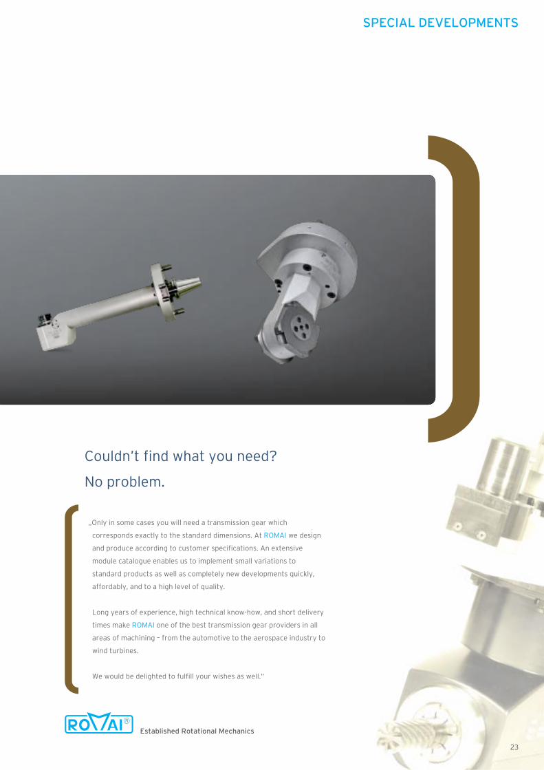
„Only in some cases you will need a transmission gear which
corresponds exactly to the standard dimensions. At ROMAI we design
and produce according to customer specifications. An extensive
module catalogue enables us to implement small variations to
standard products as well as completely new developments quickly,
affordably, and to a high level of quality.
Long years of experience, high technical know-how, and short delivery
times make ROMAI one of the best transmission gear providers in all
areas of machining – from the automotive to the aerospace industry to
wind turbines.
We would be delighted to fulfill your wishes as well.“
Couldn’t find what you need?
No problem.
Established Rotational Mechanics
SPECIAL DEVELOPMENTS
23
ROMAI Robert Maier GmbH
Tool and Machine BuildingFlorianstrasse 22 71665 Vaihingen/Enz-Horrheim Germany
Telephone: +49 70 42 / 83 21 - 0 Telefax: +49 70 42 / 83 21 - 22 E-Mail: [email protected]
www.romai.com
P10
09
67
M
ww
w.k
ach
ur.e
u
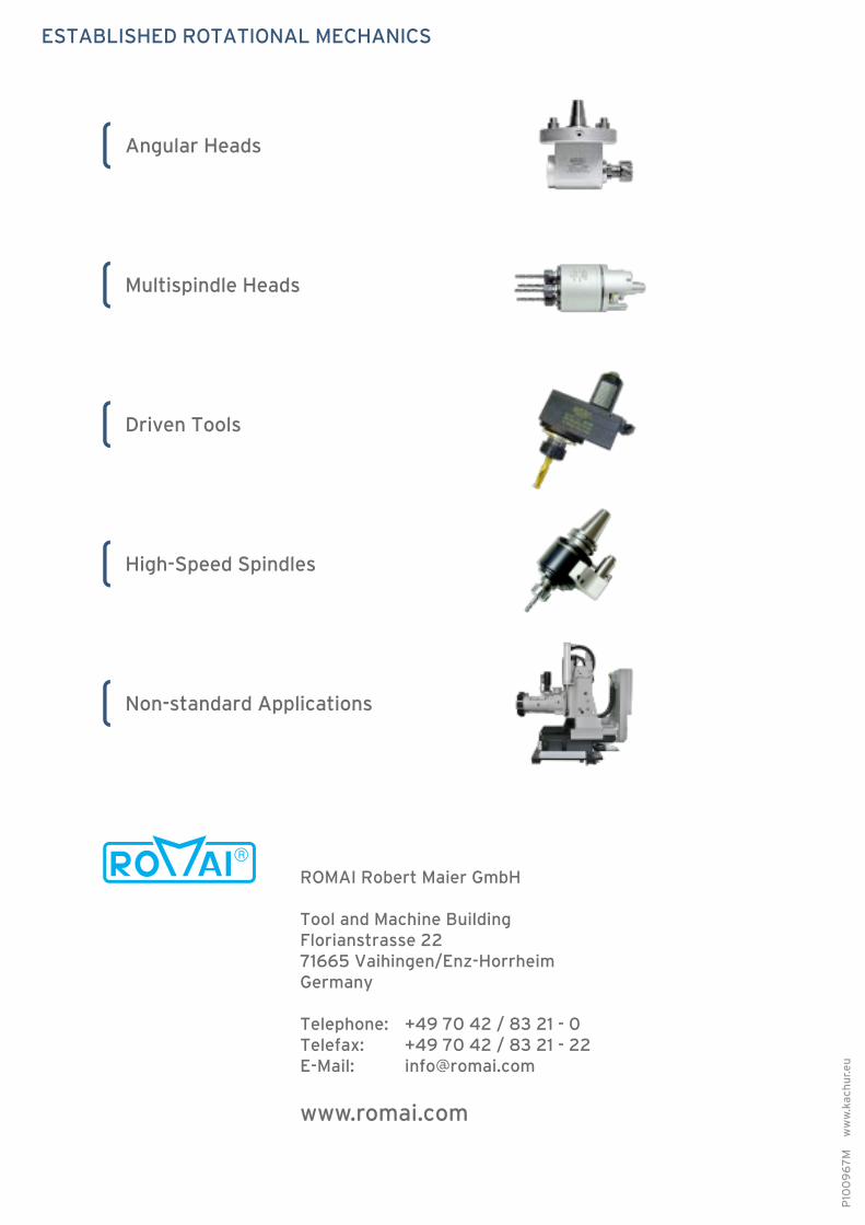
ESTABLISHED ROTATIONAL MECHANICS
Multispindle Heads
Angular Heads
Driven Tools
High-Speed Spindles
Non-standard Applications