an/gpa- an/gpa-123 sum and difference antenna group frank ... · an/gpa-123 sum and difference...
TRANSCRIPT
to i
QO CO RADC-TR-68-140
o to ;o a ^ AN/GPA-
\
AN/GPA-123 SUM AND DIFFERENCE ANTENNA GROUP
Frank T. Btnvmgo
TECHNICAL REPORT NO. RADC-TR- 68-140 April 1968
This docuiBtnt has bMo appiovad for public NIMM and sal«; its diatribution ia unlimitad.
D D C
AY221968
Rom« Air Davalopmant Cantor Air Forco Systoms Command
GriffiM Air Forco Baso, Now York
r^
Rf'producod by (he CLEARINGHOUSE
foi Fedorol Scientific & h-c1 mc il Inform,ilio'i Spnngliold Vd ?2151 / V
then US Gomoaeat inwimuß, specifications, or other data are used for say purpose other thaa a defiaitely related novotuaeat procaieaeat operatioa, the governsieot thereby incurs ao responsibility nor any eUigatioa whatsoever; sad the Uet that the government nay have fenaulated, futniahed, or la aay «ay supplied the said drawings, ^ccifications.or other data is aot to be regarded, by iaplkatioa or otherwiae, aa ia any aaaaer licensing the holder or aay other persoa or corporation, or cooveyiog aay rights or penaisaion to aiaau- factarer, uae, or aell aay pateated invention that aay ia aay ay be related thereto.
Do aot return thla copy. Retaia or destroy.

AD 669 386
AN/GPA-123 SUM AND DIFFERENCE ANTENNA GROUP
Frank T. Benvenga
Rome Air Development Center Griffiss Air Force Base, New York
April 1968
AN/GPA-123 SUM AND DIFFERENCE ANTENNA GROUP
Frank T. Benvengo
This document has been approved for public release and tale; its distribution is unlimited.
MU:, i;AFh, N.V,, I . Ma;, ■. -1
■
/
FOREWORD
A requirement exists for Implementing Interrogation Side Lobe Suppression (ISLS) for the Identification Friend or Foe (IFF) portion of the 499L AIMS Program. The 499L System Is a joint Military/Civil System for the air traffic control. The effort on the AN/6PA-123 Sum and Difference Group program was conducted by Hazel tine Corporation under Contract AF30(602)-4060. On 8 February 1966, the contract was awarded to Hazel tine for the development of two prototype Sum and Difference Antenna Systems that Incorporate side lobe suppression capabilities. On 30 June 1966, the contract was amended to Include delivery of 22 Items. The original two were for the USAF; two for Army tests; two for Navy tests; and 16 for an urgent operational requirement.
The contract for the development of this equipment did not Include a final report. Therefore, this report was written to disseminate Information on a relatively new field of antenna development for IFF systems.
The author wishes to express his gratitude to the personnel of the Identi- fication, Antenna and Flight Test Sections of RADC who assisted In the test program. Particular gratitude Is expressed to T/Sgts Richard Hunt and Philip Coffin of AFSC whose able assistance made operational tests possible.
This technical report has been reviewed by the Foreign Disclosure Policy Office (EMU) and the Office of Information (EMLS) and Is releasab-le to the Clearinghouse for Federal Scientific and Technical Information.
This technical report has been reviewed and Is approved.
Approv«^: JOSEPH M. EANNARINO OT&Chief, Surveillance Equipment ' Development Branch
Surveillance & Control Division
WILLIAM T. POPE, Jr. / Acting Chief, / Surveillance and Control
) (äuteB*i^v^_-- FOR THE COMMAND I IT »ABELMAN
Chi»f, Advanced Studie« Group
ii

ABSTRACT
Prior to the single antenna system development, ISIS was accomplished with the use of two separate antennas; a directional and an omnidirectional antenna. The same results can be achieved through the use of a single direc- tional antenna which can produce two distinct patterns.
The sum and difference patterns are obtained by feeding the antenna In two halves, by means of a hybrid Junction. In addition, this system has an added benefit of effectively sharpening the beamwldth at close ranges when Interrogating ISIS equipped airborne transponders. This Is a definite advantage for air traffic control purposes. It reduces the width of the target on the PPI thereby giving the operator a more accurate and less cluttered display.
A trade-off Is necessary, however, In that the one antenna system Is more complex and requires a greater degree of precision. Operational tests con- ducted indicate that the development was successful and ISIS Is possible using this system. Requirements of the specification and design objectives were, for the most part, achieved.
iii/iv

TABLE OF CONTENTS
Contents Page
SECTION I INTRODUCTION 1.1 Interrogation Side Lobe Suppression Using Two Antennas 2
SECTION II SYSTEM DESCRIPTION 2.1 Theory of Sum & Difference Antenna 4 2.2 Antenna Description 5 2.3 RF Switch 11 2.4 Dlplexer 11 2.5 Hybrid Coupler 12 2.6 Low-Pass Filter 12 2.7 RF Switch Driver 12 2.8 Mounting Structure 17
SECTION III FIRST ARTICLE TESTS 3.1 Pattern and Gain Tests 20 3.2 Electrical Tests 23 3.3 Environmental Tests 26 3.4 Reliability and Maintainability Tests 27 3.5 Operational Tests 27
SECTION IV CONCLUSIONS AND RECOMMENDATIONS 4.1 Conclusions Based on Test Results 28 4.2 Results of Development Effort 28
v/vi
■
SECTION I
INTRODUCTION
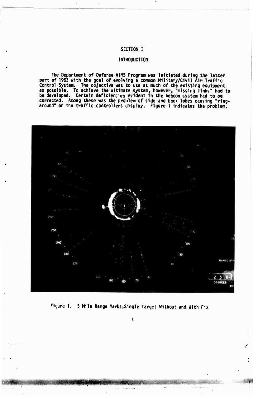
The Department of Defense AIMS Program was Initiated during the latter part of 1963 with the goal of evolving a common Military/Civil Air Traffic Control System. The objective was to use as much of the existing equipment as possible. To achieve the ultimate system, however, "missing links" had to be developed. Certain deficiencies evident In the beacon system had to be corrected. Among these was the problem of side and back lobes causing "ring- around" on the traffic controllers display. Figure 1 Indicates the problem.
Figure 1. 5 Mile Range MarkSiSlngle Target Without and With Fix
1
Displayed on the photograph are two targets: one employing side lobe suppres- sion, the other a conventional beacon. It can be seen that a controller may become confused when trying to determine the position of an aircraft without side lobe suppression.
The Setrln Fix, developed several years before the AIMS program, was the basic solution to the side lobe problem. The previous method used, when employing this fix, required the use of two separate antennas. A directional antenna provided the function of Interrogation and an omnidirectional antenna provided the side lobe suppression pulse. Modification of the airborne trans- ponder Is necessary to enable proper operation of the system.
1.1 Interrogation Side Lobe Suppression Using Two Antennas
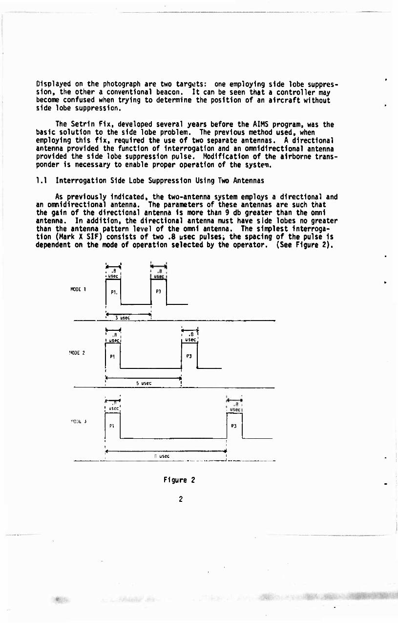
As previously Indicated, the two-antenna system employs a directional and an omnidirectional antenna. The parameters of these antennas are such that the gain of the directional antenna Is more than 9 db greater than the omnl antenna. In addition, the directional antenna must have side lobes no greater than the antenna pattern level of the omnl antenna. The simplest Interroga- tion (Mark X SIF) consists of two .8 usec pulses; the spacing of the pulse Is dependent on the mode of operation selected by the operator. (See Figure 2).
i usec
MOOt 1 PI. P3
3 usec
MODE 2
1 .8 I usec
.8 usec
PI P3
r
6 usec
• usec
MOOt J PI P3
B usec
Figure 2
2
;,. /.

The pulses are labeled PI and P3, respectively. P2 (see Figure 3) Is designated as the side lobe suppression pulse. By transmitting P2 from the omnl antenna at a predetermined position between PI and P3, side lobe suppres- sion can be accomplished In conjunction with a comparator circuit In the trans« ponder. The spacing of the pulses Is Indicated In Figure 3.
rSuSeCi
omnl gate
MOOE 1 PI
i
_irl P3
Width of Omni Gate - 1.3 MSCC Width of P2 - .8 usec
'( J1 t
j" Zusec ' 1
«o 3psec
.Susec'
MOOE 2 PI
omnl' gate
P2
rf- .Busec
P3
2usec
.ifl- Susec
MODE 3
1
'Ü^sec omnl *z—1 •Kusec
PI
i 1 ■
P3 i
P2 1 2usec
Busec"
Figure 3
PI Is transmitted at tft at which time the directional antenna Is trans- tfte mlttlng. An RF Switch Is then activated and P2 Is routed to the omnl antenna.
After P2 Is transmitted, the switch returns the system back to the directional antenna and P3 Is transmitted. The exact operation of the RF Switch will be discussed later In this report. If the aircraft transponder receives these transmissions with the level of PI and P3 at least 9 db greater than P2, it will respond to the interrogation. Outside the main beam (i.e., in the side and back lobe area) P2 is at least equal to or greater than PI and P3. When this condition exists the transponder will not reply. This simplified discus- sion of the operation serves the purpose in explaining the function of the AN/GPA-123.
It should be emphasized that the airborne equipment must be modified with side lobe suppression circuits to accomplish ISLS. The AIMS program includes the modification and procurement of transponders which possess ISLS capabilities,
'

Figure 3 shows the time relationship between P2 and the two mode pulses. P2 Is not part of the actual mode Interrogation, but Is used for side lobe suppression only.
A problem Is encountered with the two antenna systems If ground reflections are prevalent In the vertical grating lobe structure of the onml antenna which do not coincide with the reflections of the directional antenna. This Is the result of the separation of the radiation centers of the antennas. The nulls In the vertical grating pattern of the omnl antenna could cause the ISLS to be of Insufficient magnitude causing side lobe Interrogation. The one antenna system overcomes this problem.
With an understanding of the two antenna system of ISLS, the AN/GPA-123 Sum and Difference Antenna Group can now be discussed.
It would be well to point out at this time, however, that the use of a single antenna for ISLS Is not a new Idea. A limited quantity of Sum and Difference Antennas were procured by RADC from Gllflllen Corporation for Project Bamboo Tree. Stewart-Warner Electronics studied a similar ISLS system utilizing a Sum and Difference Antenna some time ago under Navy Contract NOas 56-1013-d. AMECOM Division of Litton Industries has also recently developed the AS-1769/UPX( ) Sum and Difference Antenna for the Ground Beacon Control Equipment Program. Comparison tests were conducted between the AN/GPA-123 and the AS-1769. The results are briefly discussed In Section IV of this report.
The purpose of this report, therefore. Is to document this particular effort and disseminate information not previously published. Wide dissemina- tion of this Information is desirable at this time since this system will be utilized by most Military and Civil Ground Control Approach and Terminal Area Radars in the CONUS.
SECTION II
SYSTEM DESCRIPTION
2.1 Theory of Sum and Difference Antenna
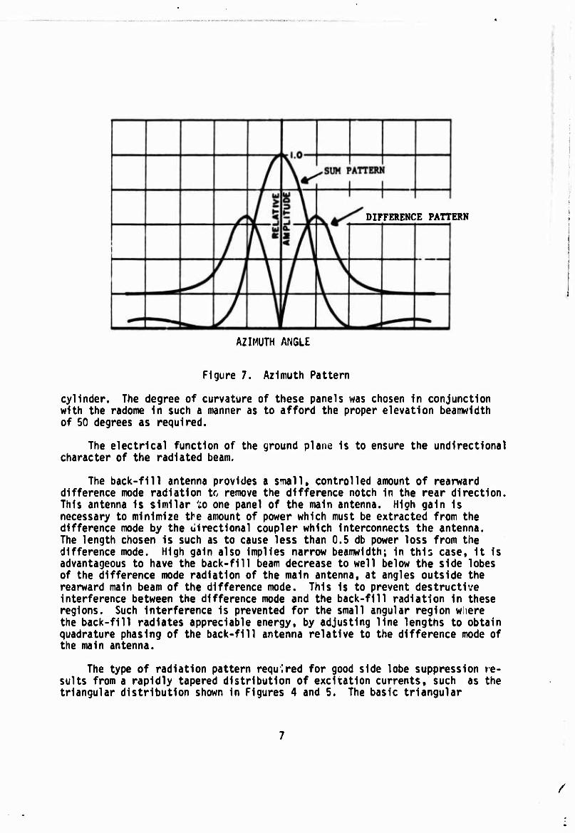
Any dipole array can be made to generate two distinct patterns by feeding each half separately either in-phase (sum pattern) or out-of-phase (difference pattern). When fed in-phase, a normal pattern will result. However, when the two halves are fed 180 degrees out-of-phase, there will be a cancellation at the center of the array. Where the peak of the in-phase pattern Is normally found, there will be a deep notch (Figure 7). Moreover, since amplitude and phase distribution.across the array Is different for each mode, the side lobe performance would differ. Feeding the array by means of a tapered distribu- tion, complete coverage of the sum side lobes by the difference pattern can be achieved. Therefore, if PI and P3 shown in Figure 3 are transmitted by the sum mode and P2 by the difference mode, a comparison of these pulses by a receiver can distinguish whether the signal is being received in the main beam of the antenna or in the side lobe area.

2.2 Antenna Description
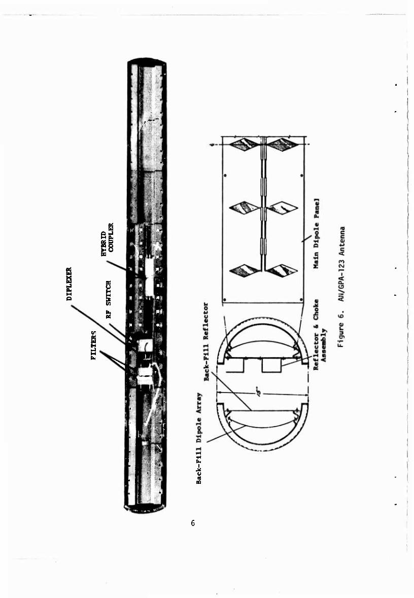
The AN/GPA-123 (Figure 6) consists of a printed dlpole array backed by a ground plane and enclosed In a tubular flberglas radome. It also contains a back-fill antenna. The diamond shaped dlpoles are a full wavelength long. The driving point Impedance of center-fed, full-wavelength dlpoles Is similar to that of a shunt resonant circuit, with the radiation resistance In parallel with the reactive elements and feed terminals. Therefore, the current through the radiation resistance Is dependent on the voltage across the dlpole and not the tuning of the reactive elements. This property of the full-wave dlpole makes It possible to guarantee proper excitation by simply Interconnecting the dlpoles with half or one wavelength transformers. The feeding arrangement con- sists of the attachment of the dlpoles to a resonant transmission line at the maximum voltage points along the standing wave pattern. Correct phasing Is achieved by spacing the dlpoles at every other voltage maximum (I.e. at one- wavelength Intervals) along the transmission line. The Impedance of the transmission lines Is stepped to different values at quarter-wavelength Inter- vals In order to provide the desired tapered excitation of the dlpoles. (Figures 4 and 5).
S\ Ä.
./L \ \
\ I t
Figure 4. Sum Excitation
r
I 1
Figure 5. Difference Illumination
Feeding the antenna in two halves by means of a standard hybrid junction, the sum and difference modes are readily obtained. The resultant antenna pattern Is illustrated In Figure 7.
The AN/GPA-123 array is divided into four printed panels, each containing four dlpoles. Each panel is centerfed by means of a coaxial transmission line and balun arrangement (quarterwave stub formed by the outside of the coaxial line shielded conductor and the ground plane). The panels on either side of the antenna center are Interconnected by means of directional couplers; the couplers are fed either In phase for the sum mode of operation or out of phase for the difference mode. The printed panels are arched to form a segment of a
/
' m*
8
i
DIFFERENCE PATTERN
AZIMUTH ANGLE
Figure 7. Azimuth Pattern
cylinder. The degree of curvature of these panels was chosen in conjunction with the radome in such a manner as to afford the proper elevation beamwidth of 50 degrees as required.
The electrical function of the ground plane is to ensure the undirectional character of the radiated beam.
The back-fill antenna provides a small, controlled amount of rearward difference mode radiation to remove the difference notch in the rear direction. This antenna is similar ':o one panel of the main antenna. High gain is necessary to minimize the amount of power which must be extracted from the difference mode by the uirectional coupler which interconnects the antenna. The length chosen is such as to cause less than 0.5 db power loss from the difference mode. High gain also implies narrow beamwidth; in this case, it is advantageous to have the back-fill beam decrease to well below the side lobes of the difference mode radiation of the main antenna, at angles outside the rearward main beam of the difference mode. This is to prevent destructive interference between the difference mode and the back-fill radiation in these regions. Such interference is prevented for the small angular region where the back-fill radiates appreciable energy, by adjusting line lengths to obtain quadrature phasing of the back-fill antenna relative to the difference mode of the main antenna.
The type of radiation pattern required for good side lobe suppression re- sults from a rapidly tapered distribution of excitation currents, such as the triangular distribution shown in Figures 4 and 5. The basic triangular
/
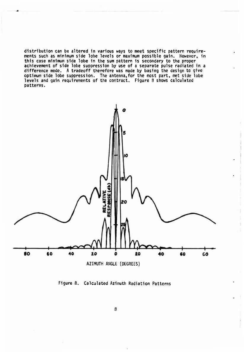
distribution can be altered in various ways to meet specific pattern require- ments such as minimum side lobe levels or maximum possible gain. However, in this case minimum side lobe in the sum pattern is secondary to the proper achievement of side lobe suppression by use of a separate pulse radiated in a difference mode. A tradeoff therefore was made by basing the design to give optimum side lobe suppression. The antenna,for the most part, met side lobe levels and gain requirements of the contract. Figure 8 shows calculated patterns.
40 20 0
AZIMUTH ANGLE (DEGREES)
Figure 8. Calculated Azimuth Radiation Patterns

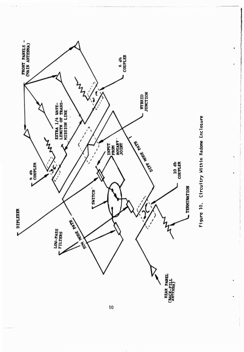
Figure 9 Is a block diagram of the system and Figure 10 a schematic representa- tion.
BACK FILL ANTENNA
i
Coupler 10 db
FILTER
ANTENNA
| Coupler 6 dlj Coupler 6 db -i
l_ HYBRID
_J A '
I
FILTER
R-F SWITCH
WITHIN ANTENNA HOUSING
n RF BIAS
DIPLEXER
Ü ( ' 1
(PART OF i ROTARY RADAR) ' JOINT l
l - J
I
i ..nr. DIPLEXER
Pj CONTROL
ll'-^- I RT-264/UPX-6, 1(Modified) i« '-. 1 p and p
R-F SWITCHt DRIVER
P. and P3 From
SIF Coder "Amber"
"^ "Red"
POWER 60 and A00 ens
Figure 9. System Block Diagram
/
O
o
a:
3 U i~
2! 3
10
2.3 RF Switch
The purpose of the RF Switch Is to route PI and P3 to the sum channel and P2 to the difference channel of the antenna. It is a solid state single pole double throw switch employinq PIN diodes as the active switching element. The switch is located within the radome and is fed in one of two manners depending upon the radar system with which it is used.
The radars for which this antenna is programmed have either one or two RF paths through the rotary joint for the IFF pulses. If only one path is avail- able, then PI, P2 and P3 and the switching gate must be fed into one line and separated again before the switch. This is accomplished by using two diplexers. The operation of the diplexers will be described later In this report. Another requirement of the rotary joint in this case is that it must be resistively coupled. Capacitive coupling will not permit passage of the d-c bias voltage required to operate the switch.
In the case of two paths through the rotary joint, coupling may be either resistive or capacitive since the switch can be located below the rotary joint and PI and P3 can be fed on one line and P2 on the other.
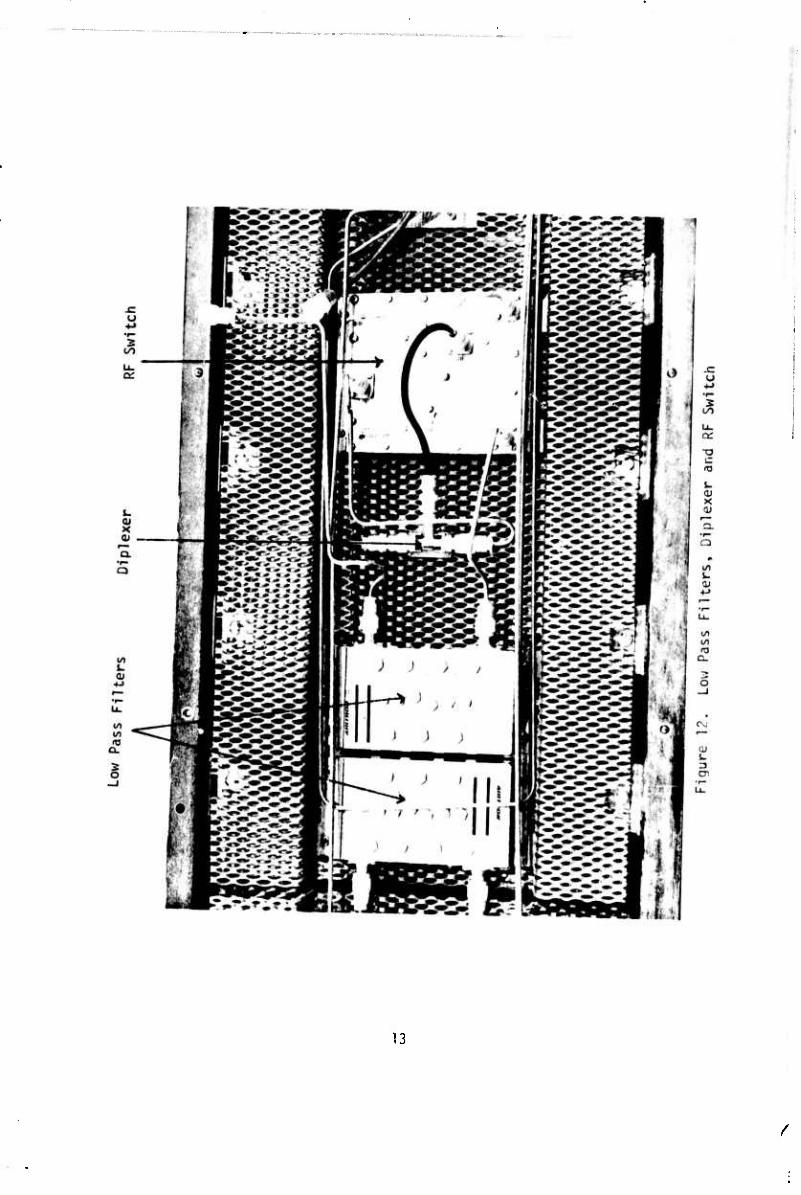
When only one path exists, the RF and bias gate are combined on the same line by one diplexer below the rotary joint. The combined signals are passed through the joint and fed into the input of the antenna. Tht other diplexer then separates the RF and bias gate, feeds PI, P2 and P3 into the RF input of the switch and the bias into the bias port of the switch. Referring back to Figure 3, the switching sequence can be followed. The switch is normally in the sum mode of operation by virtue of a 400 MA forward bias applied to the diodes. When PI arrives at the switch, it will be routed to the sum output of the switch. Just prior to the arrival of P2 (1.6 jise^ after t0) a -100V back bias is applied to the diodes. This causes P2 to be routed to the difference output of the switch. Immediately after P2 passes, the negative bias is removed, which causes the switch to return to the sum channel. The timing and generation of the -100V bias gate will be described in paragraph 2.7, RF Switch Driven. Figure 12 shows the switch on the right hand side of the photograph. The switch measures 4-1/2" x 6" x 3/8".
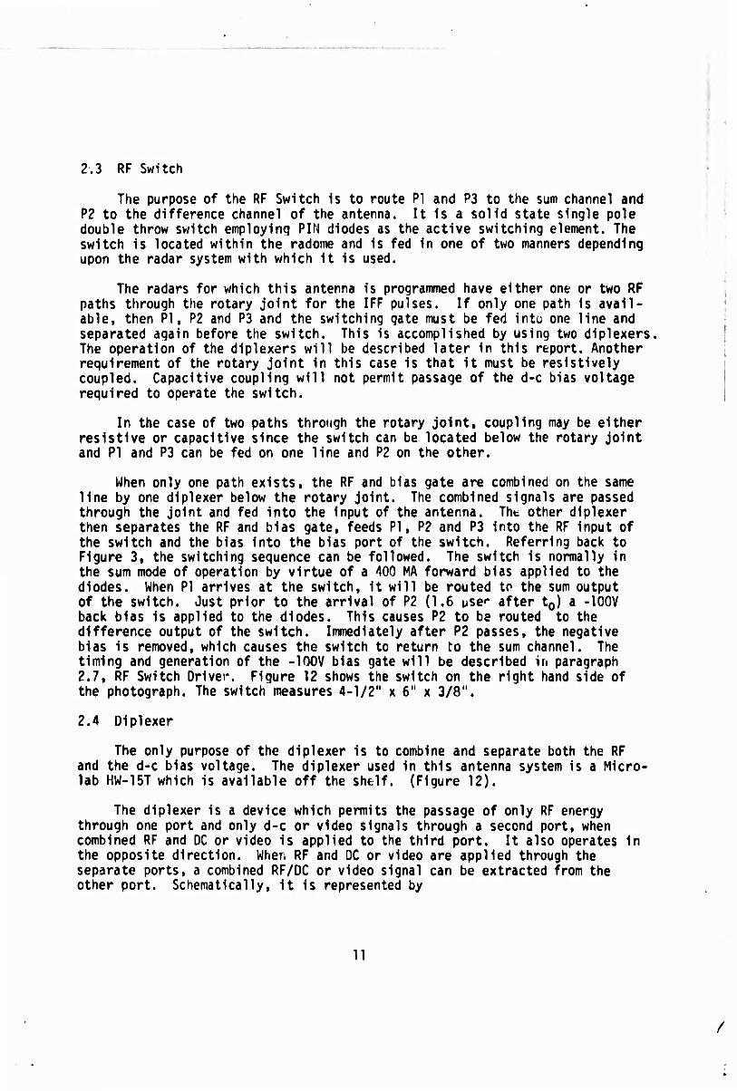
2.4 Diplexer
The only purpose of the diplexer is to combine and separate both the RF and the d-c bias voltage. The diplexer used in this antenna system is a Micro- lab HW-15T which is available off the shftlf. (Figure 12).
The diplexer is a device which permits the passage of only RF energy through one port and only d-c or video signals through a second port, when combined RF and DC or video is applied to the third port. It also operates In the opposite direction. When RF and DC or video are applied through the separate ports, a combined RF/DC or video signal can be extracted from the other port. Schematically, it is represented by
11
/
RF O 1 ( j O RF/'DC or VIDE0 DC
BLOCK > RF
CHOKE >
I
i DC
Figure 11
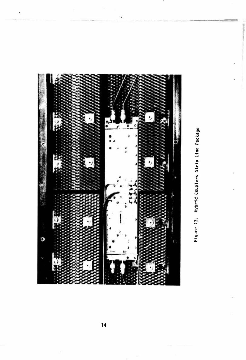
2.5 Hybrid Coupler
This component feeds the antenna panels in the proper phase relationship to create either the sum or difference pattern (Figure 13). It is a stripline device incorporating 6 db directional couplers in the output arms of the main antenna and a 10 db coupler in back-fill antenna arm (Figure 10). In the sum mode it feeds all four radiating panels in phase. In the difference mode one side of the antenna two panels) is fed 180 degrees out of phase with the other side giving the null tnat is characteristic of a difference pattern. The pack- age shown in Figure 13 contains not only the hybrid but the 6db, lOdb couplers and the end panel terminations as well.
2.6 Low-Pass Filters
These are standard filters used to prevent spurious and harmonic radiation from the antenna (Figure 12).
2.7 RF Switch Driver
This component was procured as part of the prototype equipment only and will not be required operationally. Only three were procured to enable test- ing of the antenna. The USAF is presently procuring Interrogator Set AN/TPX- 42 which will incorporate an RK Switch Driver to operate the RF Switch of this antenna. The following discussion of the driver is in order, however, to enable complete understanding of the system.
The RF Switch Driver is triggered by the two-pulse train composed of the PI and P3 trigger pulses. The RF Switch Driver has three functions (Figure 14 schematic): the generation of a P2 trigger pulse, the generation of an RF Switch Bias pulse, and the detection of faults in the RF Switch. The PI trigger causes single-si.ot A2 to disable the input to the Driver circuit for approximately 25 ^seconds so that the P3 pulse will not interfere with the RF Switch Driver circuit operation. A2 also causes singie-shots A3 and A5 to be triggered in order to generate the necessary 2 psecond delay for the P2 trigger pulse and the 1.6 usecond delay for the RF Switch Bias pulse. A3 causes A4 to trigger after 2 ^seconds, to generate the 0.8 usecond pulse width required for the ISLS (P2) trigger output. The output of A4 is amplified by driver transistor Q2 and the resulting 5-volt positive pulse is applied to the
12
13
/
CD
o a. <u c
k
'D. 3 o
I fO
2! 3 cn
14

■■ -4
Sb.^/L J&pj&a J^I&R. Ci**üir.
A.

r_ £€ JSviZ** JtS'&K. Cl*^'.
**M.
Figure 14. R-F Switch Driver Schematic
15/16
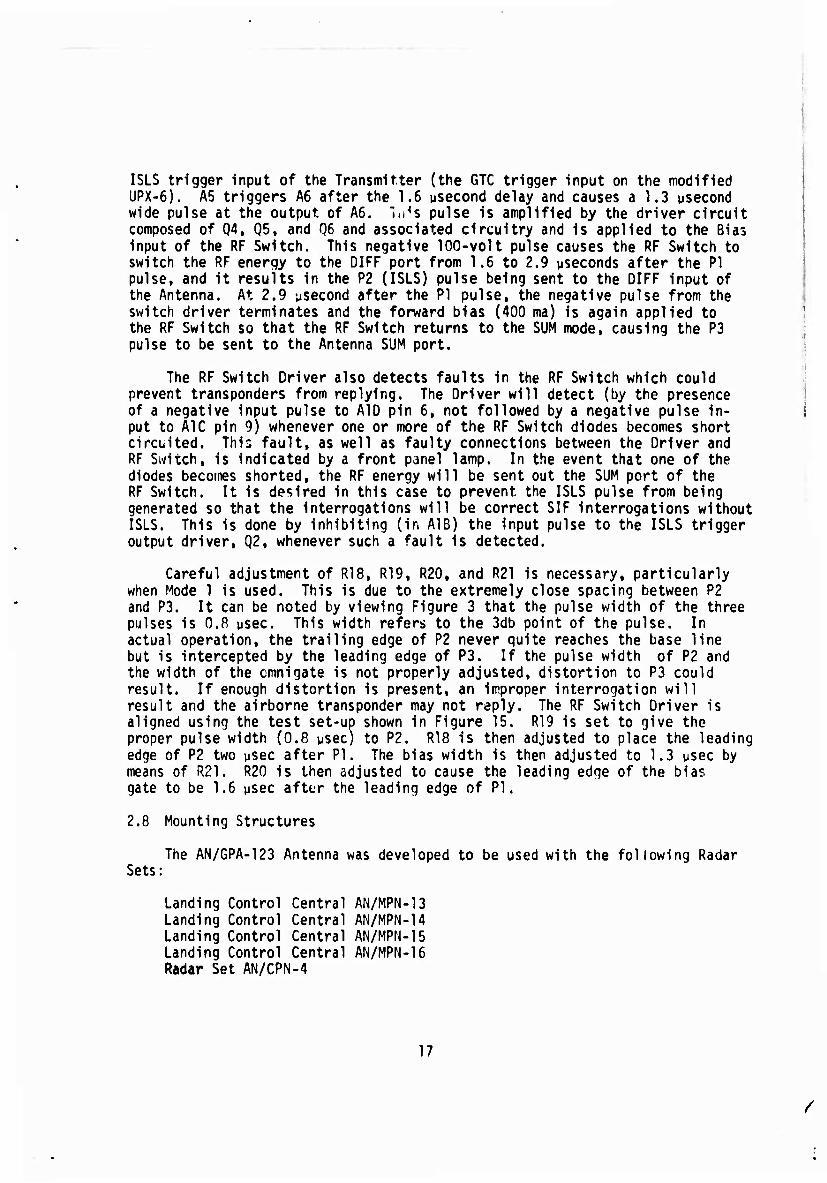
ISLS trigger input of the Transmitter (the GTC trigger input on the modified UPX-6). A5 triggers A6 after the 1.6 psecond delay and causes a 1.3 usecond wide pulse at the output of A6. "lufs pulse is amplified by the driver circuit composed of Q4, Q5, and 06 and associated circuitry and is applied to the Bias input of the RF Switch. This negative 100-volt pulse causes the RF Switch to switch the RF energy to the DIFF port from 1.6 to 2.9 ^seconds after the PI pulse, and it results in the P2 (ISLS) pulse being sent to the DIFF input of the Antenna. At 2.9 ysecond after the PI pulse, the negative pulse from the switch driver terminates and the forward bias (400 ma) is again applied to the RF Switch so that the RF Switch returns to the SUM mode, causing the P3 pulse to be sent to the Antenna SUM port.
The RF Switch Driver also detects faults in the RF Switch which could prevent transponders from replying. The Driver will detect (by the presence of a negative input pulse to AID pin 6, not followed by a negative pulse in- put to A1C pin 9) whenever one or more of the RF Switch diodes becomes short circuited. This fault, as well as faulty connections between the Driver and RF Switch, is indicated by a front panel lamp. In the event that one of the diodes becomes shorted, the RF energy will be sent out the SUM port of the RF Switch. It is desired in this case to prevent the ISLS pulse from being generated so that the interrogations will be correct SIF interrogations without ISLS. This is done by inhibiting (in A1B) the input pulse to the ISLS trigger output driver, Q2, whenever such a fault is detected.
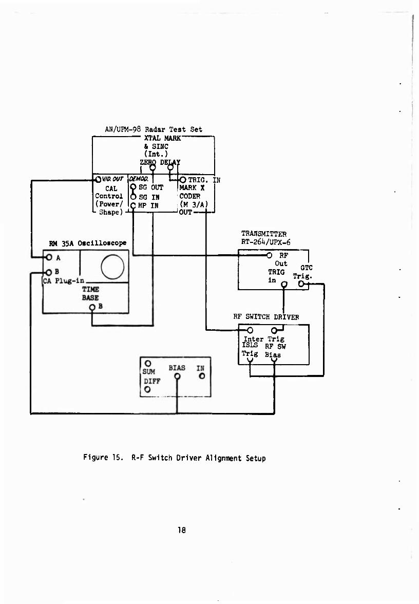
Careful adjustment of R18, R19, R20, and R21 is necessary, particularly when Mode 1 is used. This is due to the extremely close spacing between P2 and P3. It can be noted by viewing Figure 3 that the pulse width of the three pulses is 0.8 psec. This width refers to the 3db point of the pulse. In actual operation, the trailing edge of P2 never quite reaches the base line but is intercepted by the leading edge of P3. If the pulse width of P2 and the width of the cmnigate is not properly adjusted, distortion to P3 could result. If enough distortion is present, an improper interrogation will result and the airborne transponder may not reply. The RF Switch Driver is aligned using the test set-up shown in Figure 15. R19 is set to give the proper pulse width (0.8 wsec) to P2. R18 is then adjusted to place the leading edge of P2 two usec after PI. The bias width is then adjusted to 1.3 usec by means of R21. R20 is then adjusted to cause the leading edge of the bias gate to be 1.6 ysec after the leading edge of PI.
2.8 Mounting Structures
The AN/GPA-123 Antenna was developed to be used with the following Radar Sets;
Landing Control Central AN/MPN-13 Landing Control Central AN/MPN-14 Landing Control Central AN/MPN-15 Landing Control Central AN/MPN-16 Radar Set AN/CPN-4
17
/
AN/UPM-98 Radar Test Set XTAL MARK
& SINC (Int.)
DELAY
CAL Control (Power/
L Shape)
t
ZERO DEIA r
m\ to OfMW. SG OUT
SG IN CHP IN
RM 33A Oscilloscope
TRIG. MARK X CODER (M 3/A)
JOUT-
N
TRANSMITTER RT-261*/UPX-6
O RF Out
TRIG in «
n GTC
Trig.
RF SWITCH DRIVER
-o o-1
Inter Trig ISLS RF SW Trig Bias
t
Figure 15. R-F Switch Driver Alignment Setup
18
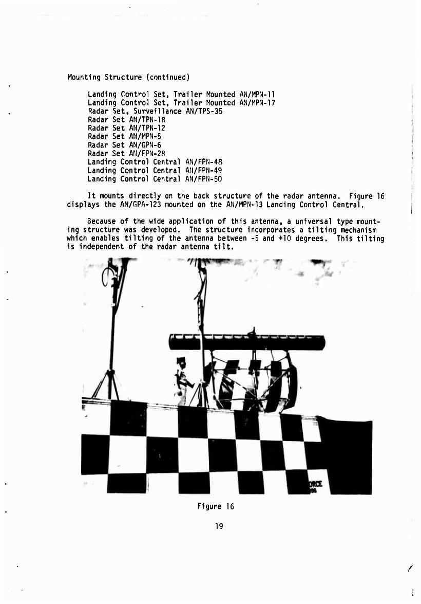
Mounting Structure (continued)
Landing Control Set, Trailer Mounted AN/MPN-ll Landing Control Set, Trailer Mounted AN/MPN-17 Radar Set, Surveillance AN/TPS-35 Radar Set AN/TPN-18 Radar Set AN/TPN-12 Radar Set AN/MPN-5 Radar Set AN/GPN-6 Radar Set AN/FPN-28 Landing Control Central AN/FPN-48 Landing Control Central AN/FPN-49 Landing Control Central AN/FPN-50
It mounts directly on the back structure of the radar antenna. Figure 16 displays the AN/r,PA-123 mounted on the AN/MPN-13 Landing Control Central.
Because of the wide application of this antenna, a universal type mount- ing structure was developed. The structure incorporates a tilting mechanism which enables tilting of the antenna between -5 and +10 degrees. This tilting is independent of the radar antenna tilt.
Figure 16
19
/
SECTION III
FIRST ARTICLE TESTS
The testing of the antenna was conducted in five phases:
Pattern and gain Testing Electrical Tests Environmental Tests Reliability and Maintainability Tests Operational Tests
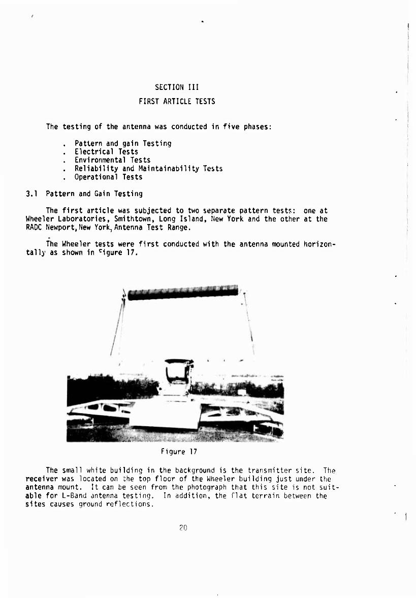
3.1 Pattern and Gain Testing
The first article was subjected to two separate pattern tests: one at Wheeler Laboratories, Smithtown, Long Island, New York and the other at the RADC Newport,New York, Antenna Test Range.
The Wheeler tests were first conducted with the antenna mounted horizon- tally as shown in cigure 17.
Figure 17
The small white building in the background is the transmitter site. The receiver was located on the top floor of the Wheeler building just under the antenna mount. It can be seen from the photograph that this site is not suit- able for L-Band antenna testing. In addition, the flat terrain between the sites causes ground reflections.
20

After taking patterns in the horizontal position,it was decided that these patterns did not reflect a true picture of the antenna capabilities. The antenna was then mounted vertically as shown in Figure 18.
Figure 18
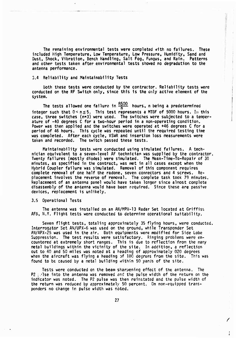
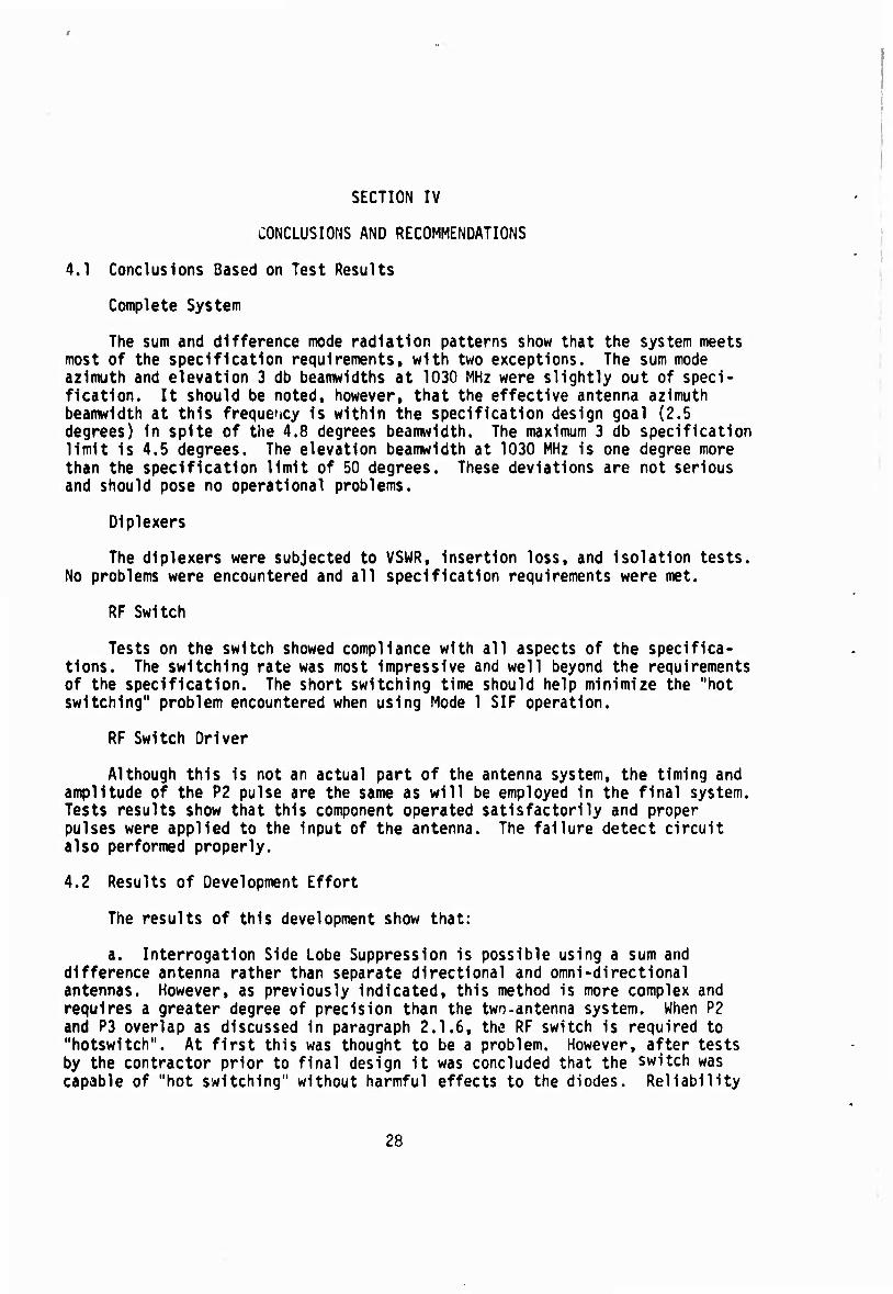
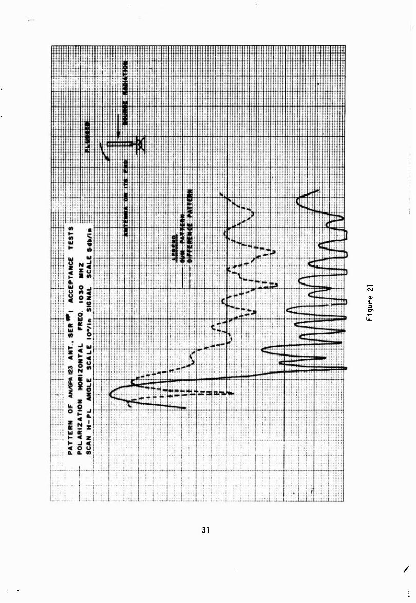
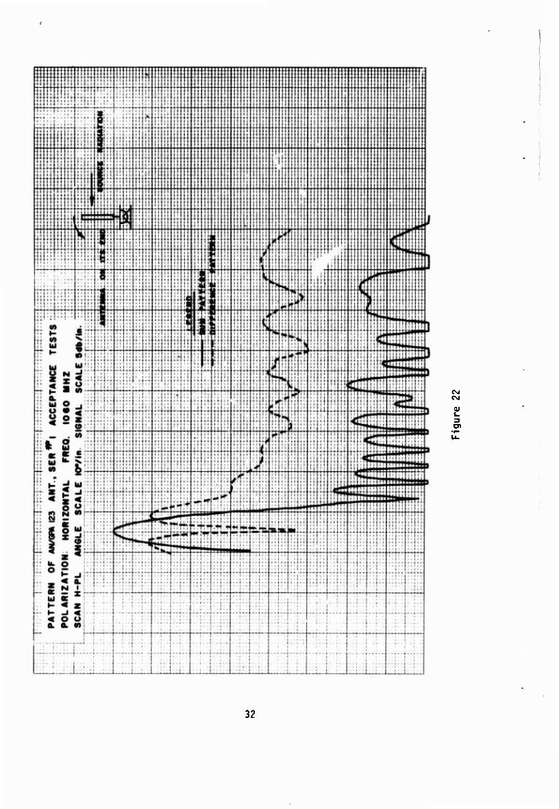
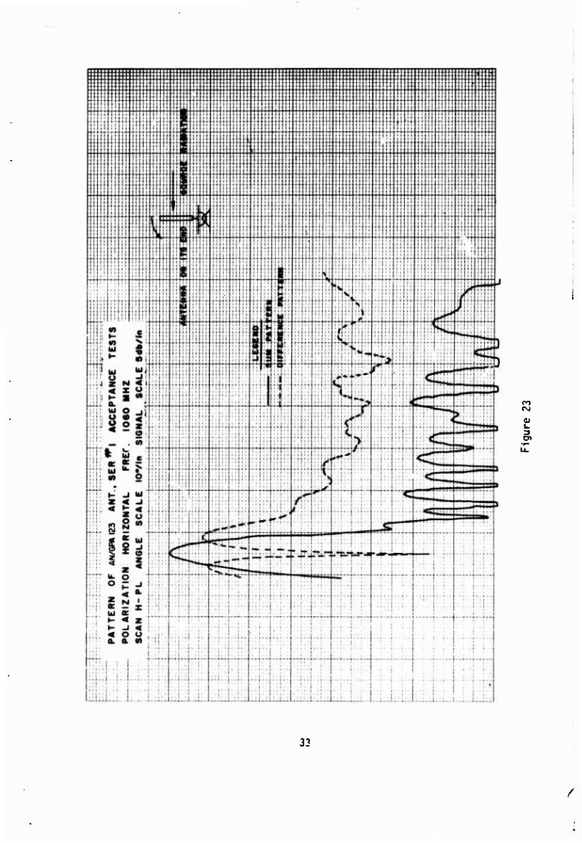
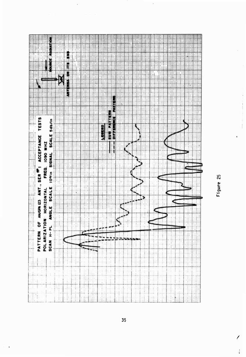
The horizontal patterns of one half the antenna were taken by tilting the antenna back on its center pivot point. The antenna was then rotated 180 degrees and the other half taken. Thus, the results as shown in Figure 20 through 25 include two patterns at each frequency. Each pattern represents one-half the antenna.
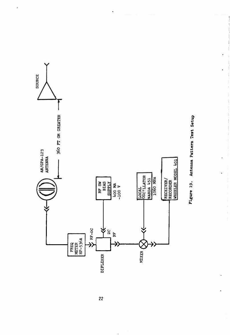
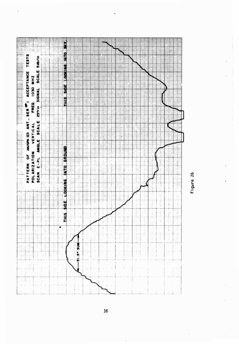
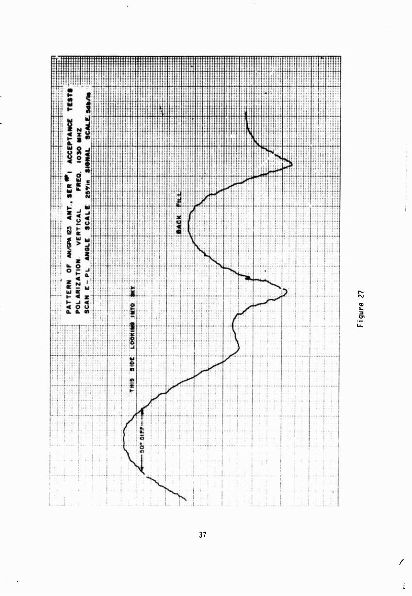
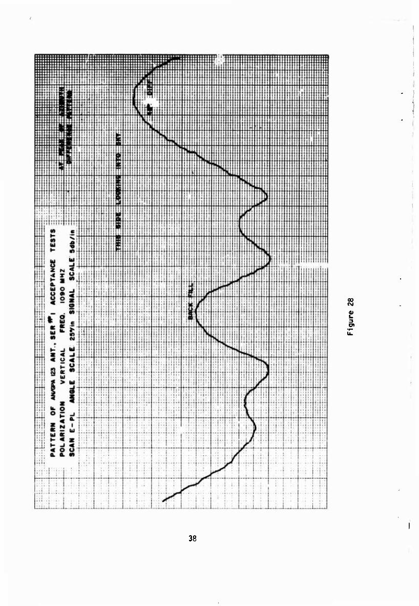
The vertical patterns as shown in Figure 26 through 29 were taken in the horizontal position rotating the antenna in the vertical plane. Both sum and difference patterns were taken. The difference patterns were taken on the nose of one of the major lobes. The set-up used is shown in Figure 19. The specification requirement for the vertical beamwidths was 50 degrees for both the sum and difference beams.
contractor's plant, the Upon completion of all First Article Tests at the antenna was installed at the RADC Newport,New York,Antenna Test Range. This was done to verify the results obtained at the Wheeler Laboratory Test Site.
21
/
o
u Q
I
^>
I s a
I
4>
O
^> ^>—
M Q
22

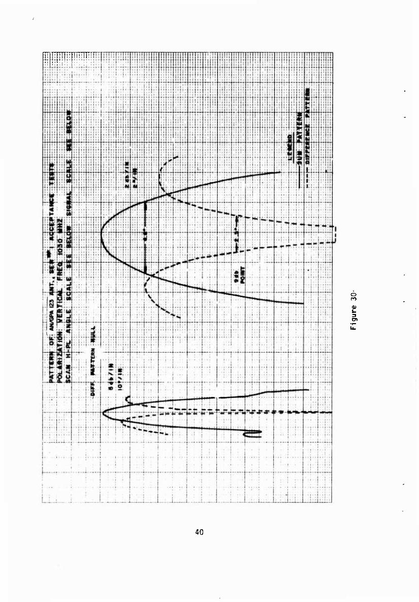
Preliminary tests with the antenna mounted horizontally showed problems with ground reflections at Newport, N.Y. as well. It was again necessary to per- form the tests with the antenna mounted vertically. The patterns taken showed results very similar to the ones at Wheeler Laboratories. The Newport patterns will not, therefore, be included In this report. The results of these tests meet or very nearly approach the specification requirements of Sum Mode Beam- width (4.5 degrees), the Effective Beamwidth (2.5 degrees) and Side Lobe Level (23 db). This is shown in Figures 30 through 32.
At this point, it would be well to explain the Effective Beamwidth. As mentioned in Para 1.1, the Side Lobe Suppression circuit in the transponder is engineered in a manner so that PI and P3 must be at least 9 db greater than P2 for the transponder to reply to an interrogation. Therefore, there is a limited area in the main beam where this condition occurs. This area is in the center portion of the sum pattern. Figures 30 through 32 show the beam- width at these points to be less than 2.5 degrees. This can therefore be considered the area in which the transponder will reply or tne effective beam- width of the antenna. It should be noted, however, that the 9-db difference will vary with the condition and alignment of the transponder among other variables.
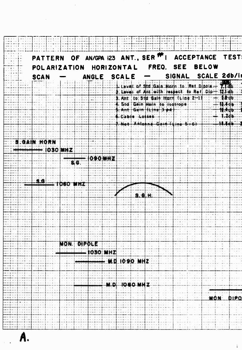
Figure 33 gives gain measurements. These tests necessitated mounting the Standard Gain Horn and the AN/GPA-123 antenna on the same mount. In order to accomplish this, a reference point had to be established, so a simple dipole was mounted below the antenna mount. The left side of Figure 33 shows the level of the standard horn with respect to the dipole. This is recorded on line 1 in the upper part of the figure. The standard gain horn is then re- moved and the AN/GPA-123 antenna mounted in its place. The right side of Figure 33 shows the level of the AN/GPA-123 antenna with respect to the ref- erence dipole. The difference is recorded on line 2 in the upper part of the figure. Line 3 represents the difference between the standard horn level and the AN/GPA-123 antenna (i.e. line 2 minus line 1). The difference is then added to the gain of the standard horn with respect to isotrope, obtained from the chart fo,- the horn (line 1). Cable losses are added (line 6). Antenna gain is then recorded on line 7. This compares favorably with the specifica- tions (20 db gain). The test set-up for the measurements is shown in Figure 34.
The maximum power handling capability of *'ie antenna was tested by applying 37 evenly spaced pulses of 0.5 wsec each at a peak power of 3 KW ond PRF of 600 (1.1% duty cycle). This surpassed the specification requirements of 2.4 KW peak power and 1% duty cycle.
3.2 Electrical Tests
These tests included VSWR,insertion loss, and isolation measurement of the complete antenna system and each individual component. Figures 35 through 37 indicate the test set-up used for these measurements.
23
/
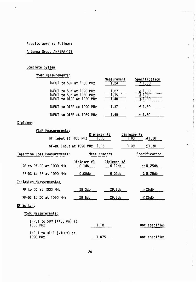
Results were as follows:
Antenna Group AN/GPA-123
Complete System
VSWR Measurements:
INPUT to SUM at 1030 MHz
INPUT to SUM at 1090 MHz INPUT to SUM at 1060 MHz INPUT to DIFF at 1030 MHz
INPUT to DIFF at 1090 MHz
INPUT to DIFF at 1069 MHz
Diplexer;
VSWR Measurements:
Measurement 1.24
Specification ^1.50
1.07 i, 1.50 1.15 $1.50 1.40 il.50
1.37 £1.50
1.48 ^ 1.50
Diplexer #3 RF Input at 1030 MHz 1.05
RF-DC Input at 1090 MHz 1.06
Diplexer #2 1.03 ^1.30
1.09 £1.30
Insertion Loss Measurements:
RF to RF-DC at 1030 MHz
RF-DC to RF at 1090 MHz
Isolation Measurements:
RF to DC at 1030 MHz
RF-DC to DC at 1090 MHz
RF Switch:
VSWR Measurements:
Measurements
Diplexer #3 O.ldb
O.OSdb
28.3db
28.6db
Diplexer #2 0.12db
O.OGdb
29.3db
29.5db
INPUT to SUM (+400 ma) at 1030 MHz
INPUT to DIFF (-100V) at 1090 MHz
1.18
Specification
^0.25db
£0.25db
> 25db
^25db
1.075
not specified
not specified
24

RF Switch Measurements Specification
Insertion Loss Measurements
INPUT to SUM (+400 ma) at 1030 MHz
INPUT to DIFF (-100V) at 1030 MHz
SUM to INPUT (+400 ma) at 1090 MHz
Isolation Measurements
INPUT to SUM (-100V) at 1030 MHz (32 db pad)
INPUT to DIFF (+400 ma) at 1030 MHz (32 db pad)
DIFF to INPUT (+400 ma) at 1090 MHz (32 db pad)
RF Switch Bias Characteristics
Amplitude
Rise Time
Fall Time
Pulse Width Range
Pulse Width Set
Delay Range
Delay Time
ISLS Trig Pulse Characteristics
Amplitude
Rise Time
Fall Time
Pulse Width Range
0.4db
0.25db
0.3db
4a+db
40+db
40+db
96 V
0.08 usec
0.14 usec
0.84 to 1.64usec
X
1.38 to 2.6 psec
X
6.4 V
0.07 usec
0.15 usec
0.48 to 1-08 psec
0.7db
^ 0.7db
^ 0.7db
> 30db
S 30db
k 30db
>85 V
^ 0.10 usec
^ 0.20 usec
0.8 to l.SMec
1.30 usec
1.50 to 2.50 usec
1.60 usec
^ 5 V
^ 0.10 usec
^ 0.20 utt
0.07 to 0.90 usec
25
/

ISIS Trig Pulse Characteristics Measurements Specifications
Pulse Width Set X 0.08 usec
Delay Range 1.48 to 2.7 usec 1.50 to 2.50 psec
Delay Set X 2.0 usec
RF Switch Fault Indication Tests
Short Circuit Fault
Fault Indicator Lighted X Check No ISLS Trig output pulse X Check
Open Circuit Fault
Fault Indicator lighted X Check
RF Switch Time Tests
Switching Time - SUM port to DIFF port 0.1 usec ^0.30 ysec
Switching Time - DIFF port to SUM port 0.06 usec ^.0.20 usec
RF Switch Switching Rate Tests
SUM port Output-Deterioration Observed Yes_ No. X
DIFF port Output-Deterioration Observed Yes- No. X
3.3 Environmental Tests
Environmental tests in most cases were conducted by the contractor. Wind and ice loading tests, however, were conducted at APGC, Eglin AFB, Florida. The antenna and mounting structure were mounted on a Navy AN/MPN-5 Radar Set undergoing other tests at APGC. Figure 38 shows the test setup used. The wind machine nozzle can be seen at the right. The antenna was subjected to 87 knot winds non-operating and 75 knot winds while rotating for one-half hour periods. Two incnes of ice loading were simulated using one-fourth inch thick lead sheets strapped onto the surface of the antenna. The antenna was then rotated for one-half hour. Inspections were conducted after each phase of the tests; no failures occurred.
26
The remaining environmental tests were completed with no failures. These included High Temperature, Low Temperature, Low Pressure, Humidity, Sand and Dust, Shock, Vibration, Bench Handling, Salt Fog, Fungus, and Rain. Patterns and other tests taken after environmental tests showed no degradation to the antenna performance.
3.4 Reliability and Maintainability Tests
Both these tests were conducted by the contractor. Reliability tests were conducted on the RF Switch only, since this is the only active element of the system.
The tests allowed one failure in ^22. hours, n being a predetermined integer such that 0<n<5. This test represents a MTBF of 5000 hours. In this case, three switches (n=3) were used. The switches were subjected to a temper- ature of -40 degrees C for a two-hour period in a non-operating condition. Power was then applied and the switches were operated at +46 degrees C for a period of 46 hours. This cycle was repeated until the required testing time was completed. After each cycle, VSWR and insertion loss measurements were taken and recorded. The switch passed these tests.
Maintainability tests were conducted using simulated failures. A tech- nician equivalent to a seven-level AF technician was supplied by the contractor. Twenty failures (mostly diodes) were simulated. The Mean-Time-To-Repair of 30 minutes, as specified in the contract, was met in all cases except when the Hybrid Coupler failure was simulated. Removal of this component requires complete removal of one half the radome, seven connectors and 4 screws. Re- placement involves the reverse of removal. The complete task took 79 minutes. Replacement of an antenna panel would have taken longer since almost complete disassembly of the antenna would have been required. Since these are passive devices, replacement is unlikely.
3.5 Operational Tests
The antenna was installed on an AN/MPN-13 Radar Set located at Griffiss AFB, N.Y. Flight tests were conducted to determine operational suitability.
Seven flight tests, totaling approximately 35 flying hours, were conducted. Interrogator Set AN/UPX-6 was used on the ground, while Transponder Set AN/APX-25 was used in the air. Both equipments were modified for Side Lobe Suppression. The test results were satisfactory. Ringing problems were en- countered at extremely short ranges. This is due to reflection from the many metal buildings within the vicinity of the site. In addition, a reflection out to 40 and 50 miles was noted at a heading of approximately 020 degrees when the aircraft was flying a heading Df 180 degrees from the site. This was found to be caused by a metal building within 50 yards of the site.
Tests were conducted on the beam sharpening effect of the antenna. The P2 , .'Ise into the antenna was removed and the pulse width of the return on the indicator was noted. The P2 pulse was then reinstated and the pulse width of the return was reduced by approximately 50 percent. On non-equipped trans- ponders no change in pulse width was noted.
27
/
SECTION IV
CONCLUSIONS AND RECOMMENDATIONS
4.1 Conclusions Based on Test Results
Complete System
The sum and difference mode radiation patterns show that the system meets most of the specification requirements, with two exceptions. The sum mode azimuth and elevation 3 db beamwidths at 1030 MHz were slightly out of speci- fication. It should be noted, however, that the effective antenna azimuth beamwidth at this frequency is within the specification design goal (2.5 degrees) in spite of the 4.8 degrees beamwidth. The maximum 3 db specification limit is 4.5 degrees. The elevation beamwidth at 1030 MHz is one degree more than the specification limit of 50 degrees. These deviations are not serious and should pose no operational problems.
Diplexors
The diplexers were subjected to VSWR, insertion loss, and isolation tests. No problems were encountered and all specification requirements were met.
RF Switch
Tests on the switch showed compliance with all aspects of the specifica- tions. The switching rate was most impressive and well beyond the requirements of the specification. The short switching time should help minimize the "hot switching" problem encountered when using Mode 1 SIF operation.
RF Switch Driver
Although this is not an actual part of the antenna system, the timing and amplitude of the P2 pulse are the same as will be employed in the final system. Tests results show that this component operated satisfactorily and proper pulses were applied to the input of the antenna. The failure detect circuit also performed properly.
4.2 Results of Development Effort
The results of this development show that:
a. Interrogation Side Lobe Suppression is possible using a sum and difference antenna rather than separate directional and omni-directional antennas. However, as previously indicated, this method is more complex and requires a greater degree of precision than the two-antenna system. When P2 and P3 overlap as discussed in paragraph 2.1.6, the RF switch is required to "hotswitch". At first this was thought to be a problem. However, after tests by the contractor prior to final design it was concluded that the switch was capable of "hot switching" without harmful effects to the diodes. Reliability
28

tests proved this point conclusively. Careful adjustment of the switch driver is necessary to insure against introducing distortion to P3.
b. Beam sharpening is possible using this technique. This sharpening effect is possible only when interrogating ISLS equipped airborne transponders. This becomes possible because the transponder will respond only when the sum signal is at least 9 db above the difference signal. By examining Figures 20 through 25, one can see that the width of the sum pattern is approximately 2.5 degrees at this point.
c. False indications from reflections may be evident where metal build- ings are within the immediate vicinity of the sitp. These may be minimized by the use of the GTC circuit available in all Interrogator Sets. It may be advisable, however, to include in the Interrogator Set a variable power out- put capability. This possibility has been considered and the results of an investigation we have conducted at the request of the SPO and FAA indicate that a reduction in power to approximately 500 watts will still give adequate interrogation range for most applications. This modification, if adopted, should reduce the reflection to a minimum. Results of our investigation have been forwarded to the AIMS SPO.
Efforts on the Ground Beacon Control Equipment Program resulted in the development of another Sum and Difference Antenna nomenclatured AS-1769/UPX( ). Comparison tests were conducted on both antennas. Pattern tests showed similar results in azimuth, elevation, and effective beanwidths. Side lobe levels were also similar in nature.
29
/

tllim!i|i|i: !! ÜIJIIMI l:
llll!;::! :;':: tli
r^
v
M ̂
Uli
;i;;||: 7;
n m
V) IÜ
in
I
u i N < < X u
W O _l ^ it< rf « o S
2 — . M
I Q UJ c
K F > UJ Ik •
H < UJ Z 1- -1 4 z <
0 U s N v>
$ at 0 X
UJ -i (9
5 z I
u. 0 0 -1 •-
< a. I !
ac - 1 ui K 1- < z »- _i ^ 4 o u a. a. en
^l^iA^
o CM
fc. o»
30
CM
0)
Oi
31
/
CM
i. 3
32
CM
<V i. 3 CD
33
/

• •■■••■•■--> •■■■■••>•»•■•■••-■■■•.>••>■■••■>■•••>■•••■■■■■••••■■«■■••■■■■■■«■■■■««■•«■■■■■««■ »«■■■■ ■■ •■ »mm mmmm ■■■« ■ •..«■>■>••.■■••>••«>■••>■•«•>■■••■-■>••«•■••■ •■■••i« ■<•■*••>■■■>•«»•«»■•■•■■■ t ••■«■■■••■•■■■•■■•| •■■■•■ ■■ ■ ■•• ••■• ••■■ ' • •• •• •••••• It • ■•• •••• ••••
iiil:ii::;:::::!i!::!!::;ni::::::il::::i:i:;iii::iiii:i:l:H:ll:::lll::: H::::::::::::::i:i >::::l li: ill:::!:::! I:::::::::::::::::::::::::::::::::::::::::::::::::::::::::::::::::::::::: ::::i:::::::::::::: ::: :::::::::::
CVJ
t. 3
34
in
<u i- 3
35
/
OsJ
C7<
36
llipl
CM
ai
37
/
00 CSJ
u
38

en CM
(U
39
/
tit ::::; :::::1;;;
o
0)
O)
40

41

42
■ I
,. ; . . 1 '1 1 *. .*
- • j .-.-4-,l i » » * ■ « -
:; i-. 1 ; ^r;
■ 1-* ■
- j-J -U-t - - • i . +-■ '■*■+• • ■
• -♦ -f .
... - i■ v — ^r ..)-..
—* + • - • f ♦-
_._.L* - . . f-t-f- -• t * ' * . | -4--+-
i
PATTERN OF AN/GRM23 ANT.SER^I ACCEPTANCE TEST! POLARIZATION HORIZONTAL FREQ. SEE BELOW SCAN — ANGLE SCALE — SIGNAL SCALE 2db/li

B.

c
to ID
K
W o w
< Of CVf) w iq on 1 H VA
S PH W
^>-
K hJ J
w So K S S
*
V
*
*>-(S^;
3
W
w
c c 0)
2 o>
I
45

M Q
G o« LA,
CO
V to
M
EH
>
m o l/N
^ o H
K • s § H W o
46

lr> t o (X 5 w
X o i4 on
"^■^ ►-1 O (U H M O EH <
c
1
r
03 W O X o w o ►J ^H a, H H « <
T Q
d,
Y o o-.
S C (0 rH
U. tH o. <
< O M O
•f
C)
4-»
■t-» w a>
w M
a o
•H
w c
17
/

e o
o
H
B as a. Q <
fe
M O
o
Ufe
s
^
X H"
o o.
T
H»
o UN
S5
± W E-" f'l
" a.
it
i CO
. J o < IT ;» o u w H »-< a 1 tr;
X
B5 w o E o' w 0\ o
a T
a
M O CQ J +
Q. 3 ♦J a»
a»
o o
■
48
UNCLASSIFIED Sfcunly ClaBstfu ation
DOCUMENT CONTROL DATA R&D (Stcutity clmiaittcmlion of title, body ol «hsfr«« t unit tntt*King imn ■tuii>-n must bv «nferad when thr •
\2a. RL POR T
i laBuUiech
1 OH'GINATING »CTiyiTT (Corpt*r»te a'tthor)
Rome Air Development Center Griffiss Air Force Base, New York 13M0
StCuR'Tv Cl ASSIFICATtON
Unclassified
J RtPOR T Ti T L t
AN/GPA-123 Sum and Difference Antenna Group
4 DESCRIPTIVE NOTES (Typ* of report mnd Indus ivv date
In House Technical Report 5 AuTHOfUSt (Flrht nmme, middle Initial, last mime,
Frank T. Benvenga
t HTPOR T DA T E
April 1963 Bm rONlRACT OH CHANT NO
b. PRO J FC T NO
499L
'«. TOTAL NO OF P*CE5
47 '(>. NO Of BF FS
*« ORIGINATOR'S REpOPT NijWf'EH'M
RAÜC-TR-68-140
l»^ O TMF R REPORT NüiSI (>4fu other numbers thai mtiv he HsslOnett thiB report)
10 DISTRIBUTION STATEMENT
This document has been approved for public release and sale; its distribution is unlimited.
ii SUPPLEMENTARY NOTES 12 SPONSORING MILITÄRS
ASU Wright-Patterson AFB, Ohio
13 *B4T B * C T
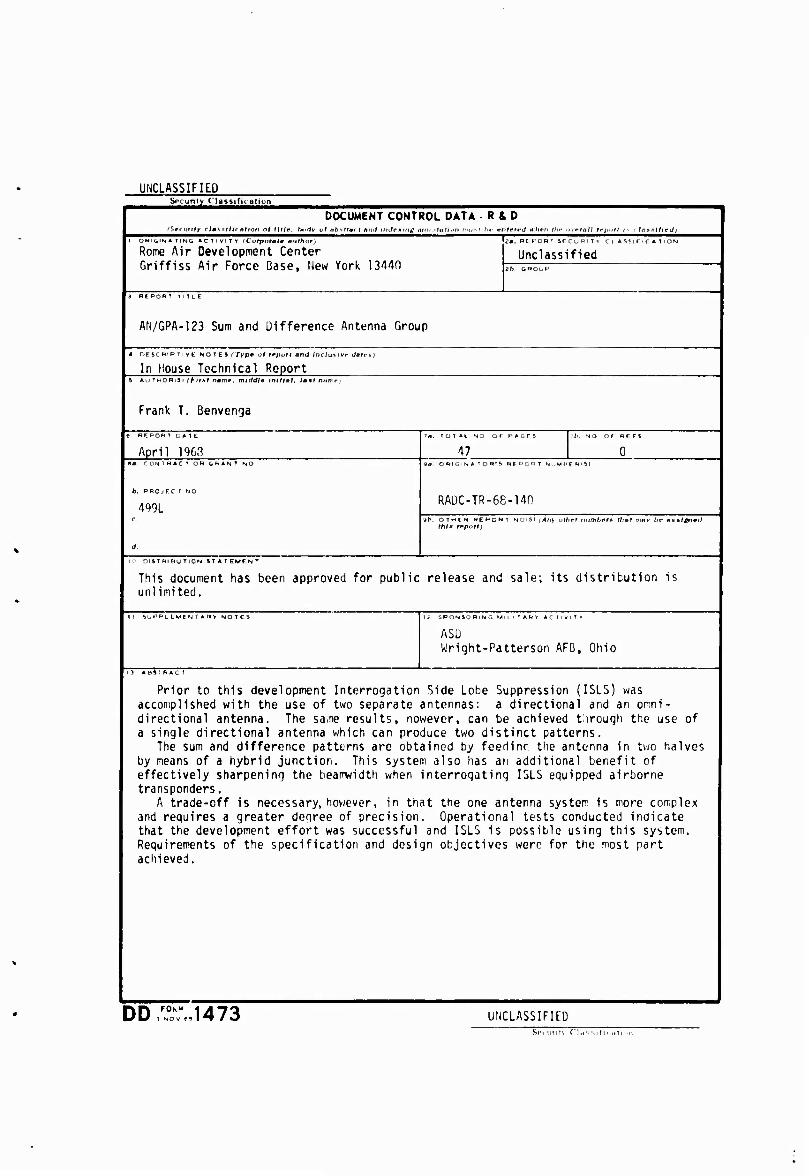
Prior to this development Interrogation Side Lobe Suppression (ISLS) was accomplished with the use of two separate antennas: a directional and an omni- directional antenna. The same results, nowevcr, can be achieved through the use of a single directional antenna which can produce two distinct patterns.
The sum and difference patterns are obtained by feedinr the antenna in two halves by means of a hybrid junction. This system also lias an additional benefit of effectively sharpening the beamwidth when interrogating ISLS equipped airborne transponders.
A trade-off is necessary, however, in that the one antenna system is more complex and requires a greater degree of precision. Operational tests conducted indicate that the development effort was successful and ISLS is possible using this system. Requirements of the specification and design objectives were for the most part achieved.
DD,FrJ473 UNCLASSIFIED St'! iirtt\ C'Kissid. Hti^n

iiNr.iA^iFirn Security ClasaificdUon
<. F ¥ WO R D S LINK M
IFF BEACONS SUM AND DIFFERENCE ANTENNAS INTERPOGATION SIDE LOBE SUPPRESSION
UNCLASSIFILD Security Classification