angle seat valves - omal · 3.2.1 ∙ pneumatic valves angle seat valves ares / atena 425 omal...
TRANSCRIPT

ANGLE SEAT VALVESCATALOGUE
www.omal.com

3 • PNEUMATIC VALVES • LIST OF CONTENTS OMAL S.p.A.
VALVOLE PNEUMATICHE ∙ INDICE
3. • VALVOLE PNEUMATICHE
3.2 • VALVOLE A FLUSSO AVVIATO
3.2.1 • ARES / ATENA
3.2.2 • ARES con attacchi speciali • Ares Flangiata • Ares da Saldare • Ares Clamp 3A
3.2.3 • ARES manuale
3.2.4 • ZEUS
3.2.5 • Accessori Ares e Zeus
3.3 • Certificati valvole pneumatiche
Pag:
422
424
436437442448
454
458
468
470

3 • PNEUMATIC VALVES • LIST OF CONTENTS OMAL S.p.A.
PNEUMATIC VALVES ∙ LIST OF CONTENTS
3. • PNEUMATIC VALVES
3.2 • ANGLE SEAT VALVES
3.2.1 • ARES / ATENA
3.2.2 • ARES with special ends • Ares Flanged • Ares Weld Ends • Ares Clamp 3A
3.2.3 • ARES manual drive
3.2.4 • ZEUS
3.2.5 • Ares and Zeus Accessories
3.3 • Pneumatic valves Certificates
Pag:
422
424
436437442448
454
458
468
470

3.2 • PNEUMATIC VALVES > ANGLE SEAT VALVES
422
OMAL S.p.A.
PN 25
Acciaio inoxARES da 3/8” a 2”; ATENA versione compatta da 3/8” a 3/4” con attuatore ø40.
Stainless steelARES from 3/8” to 2”; ATENA compact version from 3/8” to 3/4” with actuator ø40.
PN 16
BronzoZEUS: Versione in bronzo da 3/8” a 2”
BronzeZEUS: bronze versions from 3/8” to 2”
CARATTERISTICHE GENERALI:• Attacchi valvola filettati secondo EN 10226-1 Rp (ex ISO 7/1) per valvole Ares;
ISO 228/1 per valvole Zeus. Altri tipi di attacchi a richiesta.• Montaggio in ogni posizione: orizzontale, verticale, obliqua.• Gamma disponibile da 3/8” a 2” nelle versioni doppio effetto, semplice effetto
normalmente chiusa da sopra e sotto l’otturatore, semplice effetto normal-mente aperta da sotto l’otturatore.
• Conforme alla direttiva Europea 2014/68/UE “PED”.• Configurazione ATEX 2014/34/UE da richiedere in fase d'ordine.• Le diverse versioni degli azionamenti, le varie combinazioni della valvola e la
possibilità di intercettare il flusso da sopra o sotto l’otturatore, danno origine a molteplici versioni della valvola automatica.
• Nelle tabelle seguenti sono elencate le versioni standard con i principali para-metri di funzionamento.
• In base al tipo di valvola ed alla variazione di pressione ∆P che deve essere intercettata tra monte e valle della stessa, viene individuata la pressione di comando necessaria all’azionamento e conseguentemente il codice della valvola corrispondente.
• A richiesta: versioni per vuoto e per uso ossigeno.
GENERAL FEATURES:• Threaded valve ends, as per EN 10226-1 Rp (ex ISO 7/1) for Ares valves; ISO 228/1
for Zeus valves. Other types available on request. • Assembling is possible in all positions: upright, flat or angled. • Range available from 3/8” to 2” in the Double Acting versions, Spring Return N.C.
from above and below the plug, Spring Return N.O. from below the plug.• According to 2014/68/EU “PED”.• 2014/34/EU ATEX configuration to request at time of order.• The variations in the actioning of the valve, the several combinations and the
possibility to intercept the fluid from above or below the plug, originate multiple versions of the automatic valve.
• In the table below are indicated the standard versions with the main parameters.• On the basis of the kind of valve and the variations of pressure ∆P that must be
intercepted, the necessary control pressure can be individuated, and consequen-tly, the code for the corresponding valve.
• On request: versions for vacuum and oxygen service.
FLUIDO DI COMANDO:• Fluido di pilotaggio: aria compressa lubrificata o secca, gas e fluidi neutri.• Temperatura ambiente: da -10°C a +60° C.
FLUIDO INTERCETTATO:• Aria, acqua, alcool, olii, carburanti, soluzioni saline, vapore, ecc..(comunque
compatibili con A 351 CF8M O CuSn5Zn5Pb5-B).• Pressione di utilizzo da 0 a 16 / 25 bar (vapore a 180°C da 0 a 10 bar) in funzione
della misura e della versione scelta (vedi pagine seguenti).• Temperatura da -10°C a +180°C.• Viscosità massima 600 cst (mm2/s).
CONTROL MEDIA:• Driving media: compressed air, lubricated or dry, gas or neutral media.• Ambient temperature: -10°C to +60°C.
OPERATING MEDIA:• Air,water, alcohol, oil, petroleum products, saline solutions, steam, etc. (as long as
compatible with A 351 CF8M O CuSn5Zn5Pb5-B).• Pressure from 0 to 16 / 25 bar (steam from 180°C, from 0 to 10 bar) depending on
the size and model chosen (see following pages).• Temperature from –10°C to 180°C.• Max. viscosity 600 cst (mm2/s).
VALVOLE A FLUSSO AVVIATOANGLE SEAT VALVES

A F
LUSS
O A
VVIA
TOA
NG
LE S
EAT
VALV
ES
3.2 • PNEUMATIC VALVES > ANGLE SEAT VALVES
423
OMAL S.p.A.
MODALITÀ DI IMPIEGO METHODS OF USE
2
1
N.C. Normalmente chiusa bidirezionale
1
2
N.C. Normalmente chiusa con ingresso sopra l' otturatore
1
2
N.A. Normalmente aperta con ingresso sotto l'otturatore
1
2
Doppio e�etto bidirezionale
N.C. Normalmente chiusa bidirezionale. Con ingresso sotto l’otturatore si evita il colpo d’ariete. Ingresso sopra l’otturatore per fluidi compri-mibili.N.C. Normally Closed bidirectional. With the flow coming from below the plug you avoid water hammering.Flow from above the plug for condensable media.
N.C. Normalmente chiusa con ingresso sopra l’otturatore.Ingresso sopra l’otturatore per fluidi compri-mibili. N.C. Normally Closed with the flow from above the plug.Flow from above the plug for condensable media.
N.A. Normalmente aperta con ingresso sotto l’otturatore N.O. Normally Open with flow from below the plug
A richiesta versione per vuoto e per uso ossigeno On request: versions for vacuum and oxygen servicePer versioni con teste di comando differenti dallo standard contattare l'ufficio commerciale OMAL. For versions with control head different from standard executions, please contact our sales department
Doppio effetto bidirezionale Double Acting bidirectional
2
1
2
1
2
1
2
1
Versione VersionS = N.C. sottosede anticolpo d’ariete below the plug anti water hammer C = N.C. soprasede above the plugA = N.A. - N.O.D = doppio effetto - double acting
Versione VersionP = Standard X = Per uso ossigeno For oxygen
Versione Version4 = ARES - ATENA9 = ZEUS
ø teste di comando ø control heads14 = Ø 4016 = Ø 5018 = Ø 63 21 = Ø 9023 = Ø 110
Tipo di connessioni Connection types0 = Filettate Threaded - EN 10226-1 Rp (ex ISO 7/1) Ares; - ISO 228/1 Zeus.
4 = Filettate Threaded NPTPer altri attacchi ARES vedere "Ares con attac-chi speciali".For other thread see "Ares with special ends" .
YX solo per la versione ATEXYX only for ATEX ver-sion
J 4 - P G - - - - Y X9
SCHEMA DI CODIFICA VALVOLE A FLUSSO AVVIATO ANGLE SEAT VALVES CODE PLAN
Misura valvola Valve size
3 = 3/8"4 = 1/2" 4 = DN 155 = 3/4" 5 = DN 206 = 1" 6 = DN 257 = 1" 1/4 7 = DN 328 = 1" 1/2 8 = DN 409 = 2" 9 = DN 50

3.2.1 • PNEUMATIC VALVES > ANGLE SEAT VALVES > ARES / ATENA
424
OMAL S.p.A.
ARESVALVOLA INCLINATAANGLE SEAT VALVE
3
4
5
6
1
5
2
8
7

AR
ES
/ ATE
NA
3.2.1 • PNEUMATIC VALVES > ANGLE SEAT VALVES > ARES / ATENA
425
OMAL S.p.A.
FEATURES & BENEFITS
1Guarnizione posizionata nel cilindro anziché sul pistone.
Seal placed in the cylinder rather than on the piston.
Si ottiene una maggiore corsa dell'attuatore e dell'otturatore ad esso collegato garantendo grandi aperture del passaggio sulla sede (minor perdita di carico).
Longer stroke of the actuator and shutter will be achieved, granting higher flow rate (less flow loss).
Minor usura della guarnizione.
Less wear of the seal.
2Inserti della testa di comando in 303 S.S..
Piloting head inserts in 303 S.S..
Aumenta considerevolmente la resistenza alla corrosione causata da agenti esterni.
Increases considerably the corrosion resistance caused by external agents.
3
Dal DN63 pistone metallico con rivestimento in NICHEL-CHIMICO (10-15 micron).
Starting from DN63 metal piston with CHEMICAL NICKEL coating (10-15 micron).
Si riduce l'usura del pistone grazie al raggiungimento di una maggior durezza superficiale(700-750 HV).
Reduces the wear of the piston due to the achievement of a greater surface hardness (700-750 HV).
4Guarnizioni precaricate da molla.
Seals pre-loaded by spring.
Garantiscono il recupero dei giochi dovuti all'usura causata dallo scor-rimento lineare dell'albero evitando perdite vero l'esterno.
Guarantee of the recovery of the gap due to the wear caused by the sliding of the shaft avoiding leakage towards the outside part.
Consentono di mantenere energizzati le guarnizioni "chevron" (a V) compensandone le variazioni dimensionali anche a fronte di notevoli escursioni termiche.
Allow to maintain energized the "chevron" seals (V) compensating the dimensional changes even in case of huge temperature excursions.
5
Guarnizioni tipo "chevron" (a "v") con 5 guarnizioni nella parte inferiore e 3 nella parte superiore della molla.
CHEVRON seals (V shape) with 5 seals in the lower part of the spring and 3 seals in the upper part.
Si garantisce una perfetta tenuta anche dopo un numero elevato di cicli
It ensures a perfect tightness even after a high number of cycles
6Albero rullato.
Rolled shaft.
Minor usura delle guarnizioni grazie alla bassa rugosità (0,1 micron Ra) dell'albero che facilita lo scorrimento.
Less wear of the seals due to the low roughness (0,1 micron Ra) which facilitate the sliding of the shaft.
7Scartamento lungo.
Longer face to face.
Miglior fluidodinamica con riduzione delle turbolenze.
Better fluidodynamic with reduction of the turbulences.
8Otturatore oscillante/autoallineante.
Oscillating / self-aligning shutter.
Si adatta perfettamente alla sede sul corpo valvola garantendo una massima tenuta.
It fits perfectly to the valve body ensuring the maximum tightness.
Certificato ATEX.
ATEX Certificate.
Ne consente l'installazione in presenza di ambiente potenzialmente esplosivo.
Installation is allowed in a potential explosive environment.
Certificato PED. PED Certificate.
Piena conformità alle norme di sicurezza europee per i dispositivi in pressione.
Full compliance with European Safety Standards for Pressure Equipment.
3.2.1 • PNEUMATIC VALVES > ANGLE SEAT VALVES > ARES / ATENA
426
OMAL S.p.A.
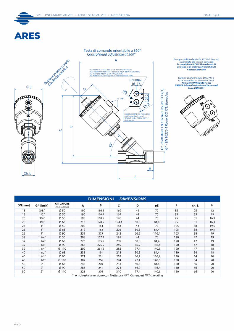
DIMENSIONI DIMENSIONSDN [mm] G * [inch]
ATTUATOREACTUATOR A B C D øE F ch. L H
15 3/8” Ø 50 190 156,5 169 44 70 85 25 1215 1/2” Ø 50 190 156,5 169 44 70 85 25 1520 3/4” Ø 50 195 160,5 176 44 70 95 31 16,320 3/4” Ø 63 213 178,5 194,4 50,5 84,4 95 31 16,325 1” Ø 50 200 164 183 44 70 105 38 19,525 1” Ø 63 219 183 202 50,5 84,4 105 38 19,525 1” Ø 90 259 223 242 66,2 116,4 105 38 1932 1 1/4” Ø 50 208 167,5 191 44 70 120 47 1932 1 1/4” Ø 63 226 185,5 209 50,5 84,4 120 47 1932 1 1/4” Ø 90 266 225,5 249 66,2 116,4 120 47 1832 1 1/4” Ø 110 302 261,5 285 77,4 140,6 120 47 1840 1 1/2” Ø 63 231 191 218 50,5 84,4 130 54 1840 1 1/2” Ø 90 271 231 258 66,2 116,4 130 54 2040 1 1/2” Ø 110 307 266 294 77,4 140,6 130 54 2050 2” Ø 63 245 200 233 50,5 84,4 150 66 2050 2” Ø 90 285 241 274 66,2 116,4 150 66 2050 2” Ø 110 321 276 310 77,4 140,6 150 66 20
* A richiesta la versione con filettatura NPT On request NPT-threading
H
B
G*
- �le
ttat
ura
EN 1
0226
-1 R
p (e
x IS
O 7
/1) D
A
45°
C
G 1/8"
Testa di comando orientabile a 360° Control head adjustable at 360°
E
Ch. L
N°2 INSERTI FILETTATATI DA G 1/8" PER LO STAFFAGGIODELL' INTERFACCIA EN 15714-3 (Namur) ALLA TESTA DI COMANDON°2 THREADED INSERTS G 1/8" FOR CLAMPINGTHE INTERFACE EN 15714-3 (Namur) TO THE CONTROL HEAD
OPTIONAL
12
12
M5
16 16
Ch.3
FORO PASSANTE PER PASSAGGIOARIA(entrambe gli inserti)THROUGH HOLE FOR AIR SUPPLY(both inserts)
F
G* -
EN
102
26-1
Rp
(ex
ISO
7/1
) thr
eade
d
Ruotare in se
nso orario
Clockwise
rotatio
n
Esempio dell'interfaccia EN 15714-3 (Namur)assemblata alla testa di comando
Disponibile A RICHIESTA nel caso dipilotaggio di elettrovalvola NAMUR
Codice: KBNJ0001
Example of NAMUR plate EN 15714-3to be assembled on the control head
Available ON REQUEST onceNAMUR Solenoid valve should be needed
Code: KBNJ0001
ARES

AR
ES
/ ATE
NA
3.2.1 • PNEUMATIC VALVES > ANGLE SEAT VALVES > ARES / ATENA
427
OMAL S.p.A.
30
25
20
15
10
5
0-20 -10 0 10 20 30 40 50 60 70 80 90
°C
100 110 120 130 140 150 160 170 180 190 200
bar
N° MATERIALI MATERIALS1 Corpo valvola Valve body A351-CF8M (316 S.S.)2 Cannotto premistoppa Sleeve A351-CF8M (316 S.S.)3 Stelo Stem 316L S.S.4* Guarnizioni stelo Stem seals PTFE-CF5* Guarnizione corpo Body seal GRAPHITE6 Otturatore Plug 316L S.S.7 Guarnizione otturatore Plug seal PTFE8 Testa di comando Actuator cylinder Poliammide PA 66 + GF 30%9 Pistone Piston Ottone nichel chimico Brass chem-nickel (PBT + GF 20% testa/head ø40 - ø50)10 Inserti di pilotaggio Threading inserts 303 S.S.* Per applicazioni alta purezza sono disponibili guarnizioni stelo in PTFE vergine e guarnizione corpo in Peek For high purity application are allowable stem seals in virgin PTFE and body seals in Peek
1
7
6
5
4
3
9
8
10
2
ARES
DIAGRAMMA PRESSIONE/TEMPERATURA TEMPERATURE/PRESSURE DIAGRAM
DIAGRAMMA T AMBIENTE/T FLUIDO INTERCETTABILE AMBIENT TEMPERATURE/MEDIA TEMPERATURE DIAGRAM
50
60
70
20
30
40
100 110 120 130 140 150 160 170 180 190 200
ø40
ø50
ø63
°C Temperatura del fluido Media temperature
°C T
empe
ratu
ra a
mbi
ente
Am
bien
t tem
pera
ture

3.2.1 • PNEUMATIC VALVES > ANGLE SEAT VALVES > ARES / ATENA
428
OMAL S.p.A.
2
5
4
6
3
1
ATENAVALVOLA INCLINATAANGLE SEAT VALVE
AR
ES
/ ATE
NA
3.2.1 • PNEUMATIC VALVES > ANGLE SEAT VALVES > ARES / ATENA
429
OMAL S.p.A.
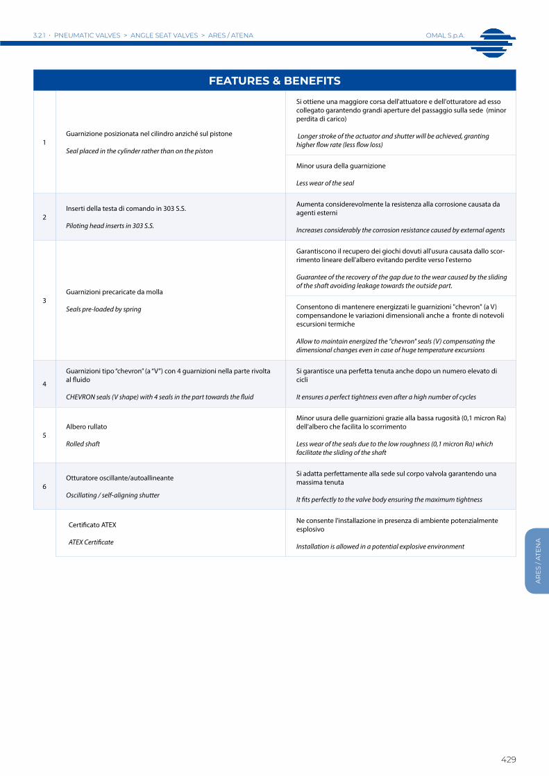
FEATURES & BENEFITS
1Guarnizione posizionata nel cilindro anziché sul pistone
Seal placed in the cylinder rather than on the piston
Si ottiene una maggiore corsa dell'attuatore e dell'otturatore ad esso collegato garantendo grandi aperture del passaggio sulla sede (minor perdita di carico)
Longer stroke of the actuator and shutter will be achieved, granting higher flow rate (less flow loss)
Minor usura della guarnizione
Less wear of the seal
2Inserti della testa di comando in 303 S.S.
Piloting head inserts in 303 S.S.
Aumenta considerevolmente la resistenza alla corrosione causata da agenti esterni
Increases considerably the corrosion resistance caused by external agents
3Guarnizioni precaricate da molla
Seals pre-loaded by spring
Garantiscono il recupero dei giochi dovuti all'usura causata dallo scor-rimento lineare dell'albero evitando perdite verso l'esterno
Guarantee of the recovery of the gap due to the wear caused by the sliding of the shaft avoiding leakage towards the outside part.
Consentono di mantenere energizzati le guarnizioni "chevron" (a V) compensandone le variazioni dimensionali anche a fronte di notevoli escursioni termiche
Allow to maintain energized the "chevron" seals (V) compensating the dimensional changes even in case of huge temperature excursions
4
Guarnizioni tipo “chevron” (a “V”) con 4 guarnizioni nella parte rivolta al fluido
CHEVRON seals (V shape) with 4 seals in the part towards the fluid
Si garantisce una perfetta tenuta anche dopo un numero elevato di cicli
It ensures a perfect tightness even after a high number of cycles
5Albero rullato
Rolled shaft
Minor usura delle guarnizioni grazie alla bassa rugosità (0,1 micron Ra) dell'albero che facilita lo scorrimento
Less wear of the seals due to the low roughness (0,1 micron Ra) which facilitate the sliding of the shaft
6Otturatore oscillante/autoallineante
Oscillating / self-aligning shutter
Si adatta perfettamente alla sede sul corpo valvola garantendo una massima tenuta
It fits perfectly to the valve body ensuring the maximum tightness
Certificato ATEX
ATEX Certificate
Ne consente l'installazione in presenza di ambiente potenzialmente esplosivo
Installation is allowed in a potential explosive environment

3.2.1 • PNEUMATIC VALVES > ANGLE SEAT VALVES > ARES / ATENA
430
OMAL S.p.A.
DIMENSIONI DIMENSIONSVersioni in CF8M CF8M version
DN [mm] G *[inch]ATTUATOREACTUATOR A B C H 39 ø61 F ch. L
15 3/8” Ø 40* 146 120,5 133,5 12 39 61 65 2515 1/2” Ø 40* 146 120,5 133,5 13 39 61 65 2520 3/4” Ø 40* 153 127,5 141,5 14,3 39 61 75 31
* A richiesta la versione con filettatura NPT On request NPT-threading
45°
B
C
39
H
G*
- File
ttat
ura
EN 1
0226
-1 R
p (e
x IS
O 7
/1)
A
G 1/8"
G 1/8"
F
Ruotare in se
nso orario
Clockwise ro
tation
G* -
EN
102
26-1
Rp
(ex
ISO
7/1
) th
read
ed
Testa di comando orientabile a 360° Control head adjustablr al 360°
61
Ch. L
ATENA

AR
ES
/ ATE
NA
3.2.1 • PNEUMATIC VALVES > ANGLE SEAT VALVES > ARES / ATENA
431
OMAL S.p.A.
30
25
20
15
10
5
0-20 -10 0 10 20 30 40 50 60 70 80 90
°C
100 110 120 130 140 150 160 170 180 190 200
bar
ATENA
10
8
9
7
1
6
3
4
2
5
DIAGRAMMA PRESSIONE/TEMPERATURA TEMPERATURE/PRESSURE DIAGRAM
DIAGRAMMA T AMBIENTE/T FLUIDO INTERCETTABILE AMBIENT TEMPERATURE/MEDIA TEMPERATURE DIAGRAM
N° MATERIALI MATERIALS1 Corpo valvola Valve body A351-CF8M (316 S.S.)2 Cannotto premistoppa Sleeve A351-CF8M (316 S.S.)3 Stelo Stem 316L S.S.4* Guarnizioni stelo Stem seals PTFE-CF5* Guarnizione corpo Body seal GRAPHITE6 Otturatore Plug 316L S.S.7 Guarnizione otturatore Plug seal PTFE8 Testa di comando Actuator cylinder Poliammide PA 66 + GF 30%9 Pistone Piston PBT + GF 20%10 Inserti di pilotaggio Threading inserts 303 S.S.* Per applicazioni alta purezza sono disponibili guarnizioni stelo in PTFE vergine e guarnizione corpo in Peek For high purity application are allowable stem seals in virgin PTFE and body seals in Peek
50
60
70
20
30
40
100 110 120 130 140 150 160 170 180 190 200
ø40
°C Temperatura del fluido Media temperature
°C T
empe
ratu
ra a
mbi
ente
Am
bien
t tem
pera
ture

3.2.1 • PNEUMATIC VALVES > ANGLE SEAT VALVES > ARES / ATENA
432
OMAL S.p.A.
diagramma 3diagram 3
testa headØ90
diagramma 4diagram 4
testa headØ110
diagramma 1diagram 1
testa headØ40-Ø50
diagramma 2diagram 2
testa headØ63
∆p b
ar
∆p b
ar
∆p b
ar
∆p b
ar
Pressione di comando Control pressure bar
Pressione di comando Control pressure bar
Pressione di comando Control pressure bar
Pressione di comando Control pressure bar
Nei diagrammi le linee tratteggiate indicano le versioni disponibili a richiesta. In the diagrams, the dash lines indicate versions available on request.
ø40: aria 0,031 dm3/cilcloø50: aria 0,051 dm3/cilclo
ø40: air 0,031 dm3/cycleø50: air 0,051 dm3/cycle
aria 0,108 dm3/cilcloair 0,108 dm3/cycle
aria 0,505 dm3/cilcloair 0,505 dm3/cycle
aria 0,238 dm3/cilcloair 0,238 dm3/cycle
CON INGRESSO DEL FLUIDO SOTTO L'OTTURATORE WITH THE FLOW FROM BELOW THE PLUG
DN [mm]
FilettaturaThreading
CODICE CODECF8M
Kvm3/h
Ø Testa comando
Ø Control head
P comando barP control barMin Max
P intercettataP operating∆P max. bar
Peso WeightKg.
KIT OTTURATORE DI RICAMBIO
PLUG SPARE KIT
KIT TESTA DI RICAMBIO
HEAD SPARE KIT15 3/8” J4SPG1403 4,5 40 (ATENA) 4,2 10 16 1 KGJP1303 J4SPG14R315 3/8” J4SPG1603 4,9 50 4 10 16 1,1 KGJP1003 J4SPG16R315 1/2” J4SPG1404 5,3 40 (ATENA) 4,2 10 16 1 KGJP1303 J4SPG14R415 1/2” J4SPG1604 5,7 50 4 10 16 1 KGJP1003 J4SPG16R420 3/4” J4SPG1405 9,2 40 (ATENA) 4,2 10 8 1,2 KGJP1305 J4SPG14R520 3/4” J4SPG1605 10,5 50 4 10 10 1,2 KGJP1005 J4SPG16R520 3/4” J4SPG1805 10,8 63 4 10 16 1,2 KGJP1005 J4SPG18R525 1” J4SPG1806 20 63 4 10 11 1,6 KGJP1006 J4SPG18R625 1” J4SPG2106 20 90 4 8 16 1,7 KGJP1106 J4SPG21R632 1 1/4” J4SPG2107 29 90 4 8 14 3 KGJP1107 J4SPG21R740 1 1/2” J4SPG2108 46 90 4 8 11 3,4 KGJP1108 J4SPG21R840 1 1/2” J4SPG2308 46,5 110 4 8 16 4 KGJP1108 J4SPG23R850 2” J4SPG2309 67 110 4 8 10 5,8 KGJP1109 J4SPG23R9
Il kit testa di ricambio comprende tutto l’articolo meno il corpo valvola. The “piloting head replacement Kit” includes the complete item without the valve body only.
Il kit otturatore di ricambio comprende l'otturatore e le guarnizioni necessarie.The shutter “replacement Kit” includes the shutter and the necessary seals.
ARES - ATENAN.C. Normalmente Chiusa bidirezionale (Con ingresso sotto l’otturatore si evita il colpo d’ariete).N.C. Normally Closed bidirectional (With the flow coming from below the plug you avoid water hammering).
CON INGRESSO DEL FLUIDO SOPRA L'OTTURATORE WITH THE FLOW FROM ABOVE THE PLUG
1 2 3 4 5 6 7 8 9 10
2524
22
20
18
16
14
12
10
8
6
4
2
0
3/8"
-1/2
"
3/4" 3/8"
-1/2
"
3/8"
-1/2
"
3/4"
50 4050
3/8"
-1/2
"
40
3/4"
10
12
14
16
18
20
22
2425
2
4
6
1 2 3 4 5 6 7 8 9 10
1"
8
0
4
6
8
10
12
14
16
18
20
22
24
1 2 3 4 5 6 7 80
25
2
1" 1"1/
4
1"1/
2
2
4
6
8
10
12
14
16
18
20
22
1 2 3 4 5 6 7 8
25
1"1/
2
2"
24
0

AR
ES
/ ATE
NA
3.2.1 • PNEUMATIC VALVES > ANGLE SEAT VALVES > ARES / ATENA
433
OMAL S.p.A.
diagramma 7diagram 7
testa headØ90
diagramma 8diagram 8
testa headØ110
diagramma 6diagram 6
testa headØ63
diagramma 5diagram 5
testa headØ40-Ø50
Nei diagrammi le linee tratteggiate indicano le versioni disponibili a richiesta. In the diagrams, the dash lines indicate versions available on request.
ø40: aria 0,031 dm3/cilcloø50: aria 0,051 dm3/cilclo
ø40: air 0,031 dm3/cycleø50: air 0,051 dm3/cycle
aria 0,108 dm3/cilcloair 0,108 dm3/cycle
aria 0,505 dm3/cilcloair 0,505 dm3/cycle
aria 0,238 dm3/cilcloair 0,238 dm3/cycle
DN [mm]
FilettaturaThreading
CODICE CODECF8M
Kvm3/h
Ø Testa comando
Ø Control head
P comando barP control barMin Max
P intercettataP operating∆P max. bar
Peso WeightKg.
KIT OTTURATORE DI RICAMBIO
PLUG SPARE KIT
KIT TESTA DI RICAMBIO
HEAD SPARE KIT15 3/8” J4CPG1403 4,5 40 (ATENA) 2,5 10 diagram n° 5 1 KGJP1303 J4CPG14R315 3/8” J4CPG1603 4,9 50 1,8 10 diagram n° 5 1 KGJP1003 J4CPG16R315 1/2” J4CPG1404 5,3 40 (ATENA) 2,,5 10 diagram n° 5 1 KGJP1303 J4CPG14R415 1/2” J4CPG1604 5,7 50 1,8 10 diagram n° 5 1 KGJP1003 J4CPG16R420 3/4” J4CPG1405 9,2 40 (ATENA) 2,5 10 diagram n° 5 1,2 KGJP1305 J4CPG14R520 3/4” J4CPG1605 10,5 50 1,8 10 diagram n° 5 1,2 KGJP1005 J4CPG16R525 1” J4CPG1806 20 63 1,8 10 diagram n° 6 1,6 KGJP1006 J4CPG18R632 1 1/4” J4CPG2107 29 90 1,8 8 diagram n° 7 3 KGJP1107 J4CPG21R740 1 1/2” J4CPG2108 46 90 1,8 8 diagram n° 7 3,7 KGJP1108 J4CPG21R840 1 1/2” J4CPG2308 46,5 110 1,8 8 diagram n° 8 4,6 KGJP1108 J4CPG23R850 2” J4CPG2109 59 90 1,8 8 diagram n° 7 4,4 KGJP1109 J4CPG21R950 2” J4CPG2309 67 110 1,8 8 diagram n° 8 5,6 KGJP1109 J4CPG23R9
Il kit testa di ricambio comprende tutto l’articolo meno il corpo valvola. The “piloting head replacement Kit” includes the complete item without the valve body only.
Il kit otturatore di ricambio comprende l'otturatore e le guarnizioni necessarie.The shutter “replacement Kit” includes the shutter and the necessary seals.
ARES - ATENAN.C. Normalmente Chiusa con ingresso sopra l’otturatoreN.C. Normally Closed with the flow from above the plug
∆p b
ar
∆p b
ar
∆p b
ar
∆p b
ar
Pressione di comando Control pressure bar
Pressione di comando Control pressure bar
Pressione di comando Control pressure bar
Pressione di comando Control pressure bar
1 2 3 4 5 6 7 8 9 100
40
1 2 3 4 5 6 7 8 9 100
6
24
22
20
18
16
14
12
10
8
4
2
25
40
3/4"
3/4"
3/8"
-1/2
"3/
8"-1
/2"
1"1"
1/4
50 50
3/8"
-1/2
"50
50
1 2 3 4 5 6 7 8 9 100
3/4" 1"
1"1/
22"
2
1"1/
4
2524
22
20
18
16
14
12
10
8
6
4
22
20
18
16
14
12
10
8
6
4
2
1 2 3 4 5 6 7 80
25
1" 1"1/
4
1"1/
2
2"
24
1"1/
2
2524
22
20
18
16
14
12
10
8
6
4
2
0 1 2 3 4 5 6 7 8
2"
3.2.1 • PNEUMATIC VALVES > ANGLE SEAT VALVES > ARES / ATENA
434
OMAL S.p.A.
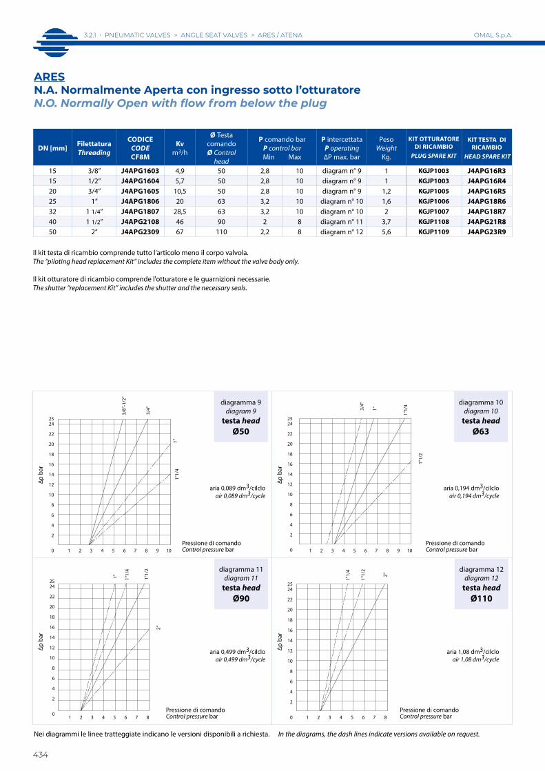
diagramma 11diagram 11
testa headØ90
diagramma 12diagram 12
testa headØ110
diagramma 9diagram 9
testa headØ50
diagramma 10diagram 10
testa headØ63
aria 0,089 dm3/cilcloair 0,089 dm3/cycle
aria 0,194 dm3/cilcloair 0,194 dm3/cycle
aria 1,08 dm3/cilcloair 1,08 dm3/cycle
aria 0,499 dm3/cilcloair 0,499 dm3/cycle
DN [mm] FilettaturaThreading
CODICE CODECF8M
Kvm3/h
Ø Testa comandoØ Control
head
P comando barP control barMin Max
P intercettataP operating∆P max. bar
PesoWeight
Kg.
KIT OTTURATORE DI RICAMBIO
PLUG SPARE KIT
KIT TESTA DI RICAMBIO
HEAD SPARE KIT
15 3/8” J4APG1603 4,9 50 2,8 10 diagram n° 9 1 KGJP1003 J4APG16R315 1/2” J4APG1604 5,7 50 2,8 10 diagram n° 9 1 KGJP1003 J4APG16R420 3/4” J4APG1605 10,5 50 2,8 10 diagram n° 9 1,2 KGJP1005 J4APG16R525 1” J4APG1806 20 63 3,2 10 diagram n° 10 1,6 KGJP1006 J4APG18R632 1 1/4” J4APG1807 28,5 63 3,2 10 diagram n° 10 2 KGJP1007 J4APG18R740 1 1/2” J4APG2108 46 90 2 8 diagram n° 11 3,7 KGJP1108 J4APG21R850 2” J4APG2309 67 110 2,2 8 diagram n° 12 5,6 KGJP1109 J4APG23R9
Il kit testa di ricambio comprende tutto l’articolo meno il corpo valvola. The “piloting head replacement Kit” includes the complete item without the valve body only.
Il kit otturatore di ricambio comprende l'otturatore e le guarnizioni necessarie.The shutter “replacement Kit” includes the shutter and the necessary seals.
ARESN.A. Normalmente Aperta con ingresso sotto l’otturatore N.O. Normally Open with flow from below the plug
Nei diagrammi le linee tratteggiate indicano le versioni disponibili a richiesta. In the diagrams, the dash lines indicate versions available on request.
∆p b
ar
∆p b
ar
∆p b
ar
∆p b
ar
Pressione di comando Control pressure bar
Pressione di comando Control pressure bar
Pressione di comando Control pressure bar
Pressione di comando Control pressure bar
3/8"
-1/2
"
0 1 2 3 4 5 6 7 8 9 10
25
3/4"
1"1/
41"
4
6
8
10
12
14
16
18
20
22
24
2
3/8"
-1/2
"
3/8"
-1/2
"
1 2 3 4 5 6 7 8 9 100
3/4"
1"
1"1/
4
1"1/
22524
22
20
18
16
14
12
10
8
6
4
2
1 2 3 4 5 6 7 80
1"1/
2
1"1/
4
1"
2"
8
10
12
14
16
18
20
22
2425
2
4
6
25
2"
1"1/
2
1"1/
4
1 2 3 4 5 6 7 8
24
22
20
18
16
14
12
10
8
6
4
2
0

AR
ES
/ ATE
NA
3.2.1 • PNEUMATIC VALVES > ANGLE SEAT VALVES > ARES / ATENA
435
OMAL S.p.A.
diagramma 13diagram 13
testa headØ50
diagramma 15diagram 15
testa headØ90
diagramma 16diagram 16
testa headØ110
diagramma 14diagram 14
testa headØ63
aria 0,14 dm3/cilcloair 0,14 dm3/cycle
aria 0,302 dm3/cilcloair 0,302 dm3/cycle
aria 1,585 dm3/cilcloair 1,585 dm3/cycle
aria 0,737 dm3/cilcloair 0,737 dm3/cycle
DN [mm] FilettaturaThreading
CODICE CODECF8M
Kvm3/h
Ø Testa comandoØ Control
head
P comando barP control barMin Max
P intercettataP operating∆P max. bar
PesoWeight
Kg.
KIT OTTURATORE DI RICAMBIO
PLUG SPARE KIT
KIT TESTA DI RICAMBIO
HEAD SPARE KIT
15 3/8” J4DPG1603 4,9 50 0,8 8 diagram n° 13 1 KGJP1003 J4DPG16R315 1/2” J4DPG1604 5,7 50 0,8 8 diagram n° 13 1 KGJP1003 J4DPG16R420 3/4” J4DPG1605 10,5 50 0,8 8 diagram n° 13 1,2 KGJP1005 J4DPG16R525 1” J4DPG1806 20 63 0,8 8 diagram n° 14 1,6 KGJP1006 J4DPG18R632 1 1/4” J4DPG1807 28,5 63 0,8 8 diagram n° 14 1,9 KGJP1007 J4DPG18R740 1 1/2” J4DPG1808 35 63 0,8 8 diagram n° 14 2,3 KGJP1008 J4DPG18R840 1 1/2” J4DPG2108 46 90 0,8 8 diagram n° 15 3,6 KGJP1108 J4DPG21R850 2” J4DPG2109 59 90 0,8 8 diagram n° 15 4,3 KGJP1009 J4DPG21R9
Il kit testa di ricambio comprende tutto l’articolo meno il corpo valvola. The “piloting head replacement Kit” includes the complete item without the valve body only.
Il kit otturatore di ricambio comprende l'otturatore e le guarnizioni necessarie.The shutter “replacement Kit” includes the shutter and the necessary seals.
ARESDoppio effetto bidirezionaleDouble acting bidirectional
Nei diagrammi le linee tratteggiate indicano le versioni disponibili a richiesta. In the diagrams, the dash lines indicate versions available on request.
∆p b
ar
∆p b
ar
∆p b
ar
∆p b
ar
Pressione di comando Control pressure bar
Pressione di comando Control pressure bar
Pressione di comando Control pressure bar
Pressione di comando Control pressure bar
1 2 3 4 5 6 7 8
2524
22
20
18
16
14
12
10
8
6
4
2
0
3/4"
3/8"
-1/2
"
1"
1"1/
4
1 2 3 4 5 6 7 8
2524
22
20
18
16
14
12
10
8
6
4
2
0
1" 1"1/
4
1"1/
2
2"
1 2 3 4 5 6 7 8
2524
22
20
18
16
14
12
10
8
6
4
2
0
1"1/
2
1 2 3 4 5 6 7 8
2524
22
20
18
16
14
12
10
8
6
4
2
0
2"
3.2.2 • PNEUMATIC VALVES > ANGLE SEAT VALVES > ARES WITH SPECIAL ENDS
436
OMAL S.p.A.
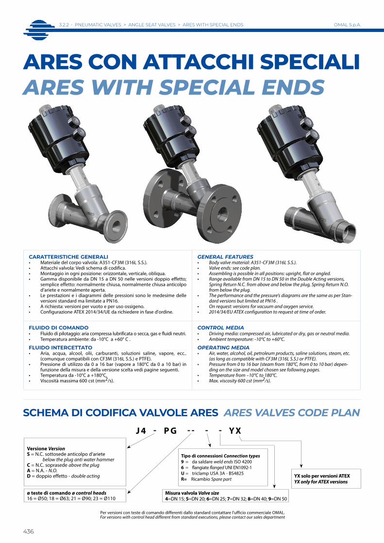
J 4 - P G - - - - Y X
Versione VersionS = N.C. sottosede anticolpo d’ariete below the plug anti water hammer C = N.C. soprasede above the plugA = N.A. - N.O.D = doppio effetto - double acting
ø teste di comando ø control heads16 = Ø50; 18 = Ø63; 21 = Ø90; 23 = Ø110
Tipo di connessioni Connection types9 = da saldare weld ends ISO 4200 6 = flangiate flanged UNI EN1092-1 U = triclamp USA 3A - BS4825R= Ricambio Spare part
Misura valvola Valve size4=DN 15; 5=DN 20; 6=DN 25; 7=DN 32; 8=DN 40; 9=DN 50
YX solo per versioni ATEXYX only for ATEX versions
Per versioni con teste di comando differenti dallo standard contattare l'ufficio commerciale OMAL. For versions with control head different from standard executions, please contact our sales department
CARATTERISTICHE GENERALI• Materiale del corpo valvola: A351-CF3M (316L S.S.). • Attacchi valvola: Vedi schema di codifica.• Montaggio in ogni posizione: orizzontale, verticale, obliqua.• Gamma disponibile da DN 15 a DN 50 nelle versioni doppio effetto;
semplice effetto: normalmente chiusa, normalmente chiusa anticolpo d’ariete e normalmente aperta.
• Le prestazioni e i diagrammi delle pressioni sono le medesime delle versioni standard ma limitate a PN16.
• A richiesta: versioni per vuoto e per uso ossigeno.• Configurazione ATEX 2014/34/UE da richiedere in fase d'ordine.
GENERAL FEATURES• Body valve material: A351-CF3M (316L S.S.).• Valve ends: see code plan.• Assembling is possible in all positions: upright, flat or angled. • Range available from DN 15 to DN 50 in the Double Acting versions,
Spring Return N.C. from above and below the plug, Spring Return N.O. from below the plug.
• The performance and the pressure’s diagrams are the same as per Stan-dard versions but limited at PN16 .
• On request: versions for vacuum and oxygen service.• 2014/34/EU ATEX configuration to request at time of order.
FLUIDO DI COMANDO• Fluido di pilotaggio: aria compressa lubrificata o secca, gas e fluidi neutri.• Temperatura ambiente: da -10°C a +60° C .
FLUIDO INTERCETTATO• Aria, acqua, alcool, olii, carburanti, soluzioni saline, vapore, ecc..
(comunque compatibili con CF3M (316L S.S.) e PTFE).• Pressione di utilizzo da 0 a 16 bar (vapore a 180°C da 0 a 10 bar) in
funzione della misura e della versione scelta vedi pagine seguenti.• Temperatura da -10°C a +180°C.• Viscosità massima 600 cst (mm2/s).
CONTROL MEDIA• Driving media: compressed air, lubricated or dry, gas or neutral media.• Ambient temperature: -10°C to +60°C.
OPERATING MEDIA• Air, water, alcohol, oil, petroleum products, saline solutions, steam, etc.
(as long as compatible with CF3M (316L S.S.) or PTFE).• Pressure from 0 to 16 bar (steam from 180°C, from 0 to 10 bar) depen-
ding on the size and model chosen see following pages.• Temperature from –10°C to 180°C.• Max. viscosity 600 cst (mm2/s).
ARES CON ATTACCHI SPECIALIARES WITH SPECIAL ENDS
SCHEMA DI CODIFICA VALVOLE ARES ARES VALVES CODE PLAN

ARES
ATT
ACCH
I SPE
CIAL
IA
RES
SP
ECIA
L EN
DS
3.2.2 • PNEUMATIC VALVES > ANGLE SEAT VALVES > ARES WITH SPECIAL ENDS
437
OMAL S.p.A.
In neretto gli accoppiamenti consigliati. Altre combinazioni a richiesta. Suggested executions are in bold. Other combinations on request.
DIMENSIONI DIMENSIONSDN [mm] Testa di comando
Control head A B C D øE F H L øM øN øP øQ øR
15 Ø 50 182,5 156 203,5 44 70 130 16 14 18,1 45 95 65 1420 Ø 50 192,3 160 212,5 44 70 150 18 16 23,7 58 105 75 1420 Ø 63 210,3 178 230,5 50,5 84,4 150 18 16 23,7 58 105 75 1425 Ø 50 197,36 164 221,5 44 70 160 18 16 29,7 68 115 85 1425 Ø 63 216,36 182 239,5 50,5 84,4 160 18 16 29,7 68 115 85 1425 Ø 90 256,36 222 279,5 66,2 116,4 160 18 16 29,7 68 115 85 1432 Ø 50 202,5 168 238 44 70 180 18 16 38,4 78 140 100 1832 Ø 63 220,5 186 256 50,5 84,4 180 18 16 38,4 78 140 100 1832 Ø 90 260,5 226 296 66,2 116,4 180 18 16 38,4 78 140 100 1832 Ø 110 296,5 261 331 77,4 140,6 180 18 16 38,4 78 140 100 1840 Ø 63 228,6 190 265 50,5 84,4 200 18 15 44,3 88 150 110 1840 Ø 90 268,6 230 305 66,2 116,4 200 18 15 44,3 88 150 110 1840 Ø 110 304,2 266 341 77,4 140,6 200 18 15 44,3 88 150 110 1850 Ø 63 241,87 200 282,5 50,5 84,4 230 18 15 55,7 102 165 125 1850 Ø 90 281,87 240 322,5 66,2 116,4 230 18 15 55,7 102 165 125 1850 Ø 110 317,87 276 358,5 77,4 140,6 230 18 15 55,7 102 165 125 18
VALVOLA FLANGIATA ANSI 150RF SCART.ASME B16.10 A1ANSI 150RF FLANGED VALVE FACE TO FACE ASME B16.10 A1
DN [mm] H L øN øP øQ øR F15 12 10,4 35 89 61 16 10820 13 11,4 43 98 70 16 117,525 15 13,4 51 108 80 16 12732 16 14,4 64 118 89 16 14040 18 16,4 73 127 99 16 16550 19 17,4 93 152 121 19 178
VALVOLA FLANGIATA RIDOTTAREDUCED FLANGES VALVES
DN [mm] H øP øQ øR F15 7 70 50 7 104,520 8 75 55 9 119,525 9 80 60 9 134,532 9 90 70 9 149,540 10 100 80 9 164,550 10 110 90 11 179,5
A richiesta versioni:flangiate ASME 150 RF;flangiate ridotte
On request versions:flanges according to ASME 150 RF;reduced flanges
B
45°
D
A
C
Q
R
M
45°
Testa di comando orientabile a 360° Control head adjustable at 360°
G 1/8"
Ruotare in se
nso orario
Clockwise
rotatio
n
L H
E
F H
P
L
N
OPTIONAL
N°2 INSERTI FILETTATATI DA G 1/8" PER LO STAFFAGGIODELL' INTERFACCIA EN 15714-3 (Namur) ALLA TESTA DI COMANDON°2 THREADED INSERTS G 1/8" FOR CLAMPINGTHE INTERFACE EN 15714-3 (Namur) TO THE CONTROL HEAD
FORO PASSANTE PER PASSAGGIOARIA(entrambe gli inserti)THROUGH HOLE FOR AIR SUPPLY(both inserts)
12
12
M5
16 16
Ch.3
Esempio dell'interfaccia EN 15714-3 (Namur)assemblata alla testa di comando
Disponibile A RICHIESTA nel caso dipilotaggio di elettrovalvola NAMUR
Codice: KBNJ0001
Example of NAMUR plate EN 15714-3to be assembled on the control head
Available ON REQUEST onceNAMUR Solenoid valve should be needed
Code: KBNJ0001
PN 16
ARES FLANGIATE UNI EN 1092-1 FLANGED UNI EN 1092-1

3.2.2 • PNEUMATIC VALVES > ANGLE SEAT VALVES > ARES WITH SPECIAL ENDS
438
OMAL S.p.A.
CON INGRESSO DEL FLUIDO SOTTO L'OTTURATORE WITH THE FLOW FROM BELOW THE PLUG
DN [mm]CODICE
CODECF3M
Kvm3/h
Ø Testa comandoØ Control head
P comando barP control barMin Max
P intercettataP operating∆P max. bar
Peso WeightKg.
KIT OTTURATORE DI RICAMBIO
PLUG SPARE KIT
KIT TESTA DI RICAMBIO
HEAD SPARE KIT
15 J4SPG1664 5,7 50 4 10 16 2,4 KGJP1003 J4SPG16R420 J4SPG1665 10,5 50 4 10 10 3,2 KGJP1005 J4SPG16R520 J4SPG1865 10,8 63 4 10 16 3,1 KGJP1005 J4SPG18R525 J4SPG1866 20 63 4 10 11 3,8 KGJP1006 J4SPG18R625 J4SPG2166 20 90 4 8 16 3,9 KGJP1106 J4SPG21R632 J4SPG2167 29 90 4 8 14 6,6 KGJP1107 J4SPG21R740 J4SPG2168 46 90 4 8 11 7,5 KGJP1108 J4SPG21R840 J4SPG2368 46,5 110 4 8 16 8,1 KGJP1108 J4SPG23R850 J4SPG2369 67 110 4 8 10 11,2 KGJP1109 J4SPG23R9
Il kit testa di ricambio comprende tutto l’articolo meno il corpo valvola. The “piloting head replacement Kit” includes the complete item without the valve body only.
Il kit otturatore di ricambio comprende l'otturatore e le guarnizioni necessarie.The shutter “replacement Kit” includes the shutter and the necessary seals.
diagramma 1diagram 1
testa headØ40-Ø50
diagramma 3diagram 3
testa headØ90
diagramma 4diagram 4
testa headØ110
diagramma 2diagram 2
testa headØ63
ø40: aria 0,031 dm3/cilcloø50: aria 0,051 dm3/cilclo
ø40: air 0,031 dm3/cycleø50: air 0,051 dm3/cycle
aria 0,108 dm3/cilcloair 0,108 dm3/cycle
aria 0,505 dm3/cilcloair 0,505 dm3/cycle
aria 0,238 dm3/cilcloair 0,238 dm3/cycle
ARES FLANGIATE FLANGEDN.C. Normalmente Chiusa bidirezionale (Con ingresso sotto l’otturatore si evita il colpo d’ariete).N.C. Normally Closed bidirectional (With the flow coming from below the plug you avoid water hammering).
Nei diagrammi le linee tratteggiate indicano le versioni disponibili a richiesta. In the diagrams, the dash lines indicate versions available on request.
CON INGRESSO DEL FLUIDO SOPRA L'OTTURATORE WITH THE FLOW FROM ABOVE THE PLUG
∆p b
ar∆p
bar
∆p b
ar∆p
bar
Pressione di comando Control pressure bar
Pressione di comando Control pressure bar
Pressione di comando Control pressure bar
Pressione di comando Control pressure bar
1 2 3 4 5 6 7 8 9 10
3/4"
0
3/8"
-1/2
"
3/8"
-1/2
"
3/4"
50
40
40
50
6
14
12
10
8
4
2
16
1 2 3 4 5 6 7 8
1" 1"1/
4
1"1/
2
6
14
12
10
8
0
4
2
16
0
3/4"
1"
1 2 3 4 5 6 7 8 9 10
6
14
12
10
8
4
2
16
1 2 3 4 5 6 7 8
1"1/
22"
16
14
12
10
8
6
4
2
0

ARES
ATT
ACCH
I SPE
CIAL
IA
RES
SP
ECIA
L EN
DS
3.2.2 • PNEUMATIC VALVES > ANGLE SEAT VALVES > ARES WITH SPECIAL ENDS
439
OMAL S.p.A.
DN [mm]CODICE
CODECF3M
Kvm3/h
Ø Testa comandoØ Control head
P comando barP control barMin Max
P intercettataP operating∆P max. bar
Peso WeightKg.
KIT OTTURATORE DI RICAMBIO
PLUG SPARE KIT
KIT TESTA DI RICAMBIO
HEAD SPARE KIT
15 J4CPG1664 5,7 50 1,8 10 diagram n° 5 1 KGJP1003 J4CPG16R420 J4CPG1665 10,5 50 1,8 10 diagram n° 5 1,2 KGJP1005 J4CPG16R525 J4CPG1866 20 63 1,8 10 diagram n° 6 1,6 KGJP1006 J4CPG18R632 J4CPG2167 29 90 1,8 8 diagram n° 7 3 KGJP1107 J4CPG21R740 J4CPG2168 46 90 1,8 8 diagram n° 7 3,7 KGJP1108 J4CPG21R850 J4CPG2169 59 90 1,8 8 diagram n° 7 4,4 KGJP1109 J4CPG21R940 J4CPG2368 46,5 110 1,8 8 diagram n° 8 4,6 KGJP1108 J4CPG23R850 J4CPG2369 67 110 1,8 8 diagram n° 8 5,6 KGJP1109 J4CPG23R9
Il kit testa di ricambio comprende tutto l’articolo meno il corpo valvola. The “piloting head replacement Kit” includes the complete item without the valve body only.
Il kit otturatore di ricambio comprende l'otturatore e le guarnizioni necessarie.The shutter “replacement Kit” includes the shutter and the necessary seals.
diagramma 6diagram 6
testa headØ63
diagramma 5diagram 5
testa headØ40-Ø50
diagramma 7diagram 7
testa headØ90
diagramma 8diagram 8
testa headØ110
ø40: aria 0,031 dm3/cilcloø50: aria 0,051 dm3/cilclo
ø40: air 0,031 dm3/cycleø50: air 0,051 dm3/cycle
aria 0,108 dm3/cilcloair 0,108 dm3/cycle
aria 0,505 dm3/cilcloair 0,505 dm3/cycle
aria 0,238 dm3/cilcloair 0,238 dm3/cycle
ARES FLANGIATE FLANGEDN.C. Normalmente Chiusa con ingresso sopra l’otturatore.N.C. Normally Closed with the flow from above the plug.
Nei diagrammi le linee tratteggiate indicano le versioni disponibili a richiesta. In the diagrams, the dash lines indicate versions available on request.
∆p b
ar∆p
bar
∆p b
ar∆p
bar
Pressione di comando Control pressure bar
Pressione di comando Control pressure bar
Pressione di comando Control pressure bar
Pressione di comando Control pressure bar
3/8"
-1/2
"
1 2 3 4 5 6 7 8 9 10
6
3/4"
3/8"
-1/2
"
1" 3/4"
50 50
40
50 40 50 1"1/
4
14
12
10
8
0
4
2
16
1 2 3 4 5 6 7 80
1"1/
4
1"1/
2
2"1"
8
10
12
14
16
2
4
6
3/4"
1"
1"1/
22"
1"1/
4
1 2 3 4 5 6 7 8 9 10
16
14
12
10
8
6
4
2
0
14
12
10
8
16
4
2
1 2 3 4 5 6 7 80
2"
6
1"1/
2
3.2.2 • PNEUMATIC VALVES > ANGLE SEAT VALVES > ARES WITH SPECIAL ENDS
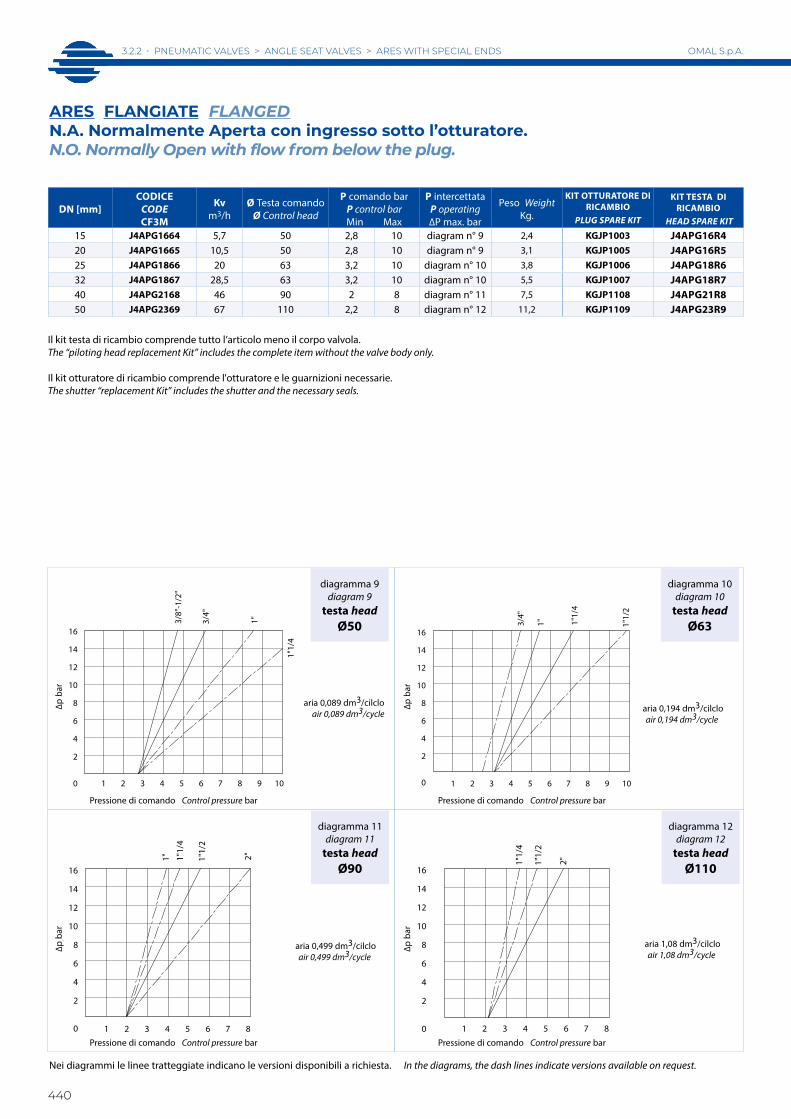
440
OMAL S.p.A.
DN [mm]CODICE
CODECF3M
Kvm3/h
Ø Testa comandoØ Control head
P comando barP control barMin Max
P intercettataP operating∆P max. bar
Peso WeightKg.
KIT OTTURATORE DI RICAMBIO
PLUG SPARE KIT
KIT TESTA DI RICAMBIO
HEAD SPARE KIT
15 J4APG1664 5,7 50 2,8 10 diagram n° 9 2,4 KGJP1003 J4APG16R420 J4APG1665 10,5 50 2,8 10 diagram n° 9 3,1 KGJP1005 J4APG16R525 J4APG1866 20 63 3,2 10 diagram n° 10 3,8 KGJP1006 J4APG18R632 J4APG1867 28,5 63 3,2 10 diagram n° 10 5,5 KGJP1007 J4APG18R740 J4APG2168 46 90 2 8 diagram n° 11 7,5 KGJP1108 J4APG21R850 J4APG2369 67 110 2,2 8 diagram n° 12 11,2 KGJP1109 J4APG23R9
Il kit testa di ricambio comprende tutto l’articolo meno il corpo valvola. The “piloting head replacement Kit” includes the complete item without the valve body only.
Il kit otturatore di ricambio comprende l'otturatore e le guarnizioni necessarie.The shutter “replacement Kit” includes the shutter and the necessary seals.
diagramma 9diagram 9
testa headØ50
diagramma 11diagram 11
testa headØ90
diagramma 12diagram 12
testa headØ110
diagramma 10diagram 10
testa headØ63
aria 0,089 dm3/cilcloair 0,089 dm3/cycle aria 0,194 dm3/cilclo
air 0,194 dm3/cycle
aria 1,08 dm3/cilcloair 1,08 dm3/cycle
aria 0,499 dm3/cilcloair 0,499 dm3/cycle
ARES FLANGIATE FLANGEDN.A. Normalmente Aperta con ingresso sotto l’otturatore.N.O. Normally Open with flow from below the plug.
Nei diagrammi le linee tratteggiate indicano le versioni disponibili a richiesta. In the diagrams, the dash lines indicate versions available on request.
∆p b
ar∆p
bar
∆p b
ar∆p
bar
Pressione di comando Control pressure bar
Pressione di comando Control pressure bar
Pressione di comando Control pressure bar
Pressione di comando Control pressure bar
3/4"
1"3/8"
-1/2
"
2
0
8
10
12
14
16
4
6
1"1/
4
1 2 3 4 5 6 7 8 9 10
1 2 3 4 5 6 7 8
1" 1"1/
2
1"1/
4
2"
0
14
12
10
8
16
4
2
6
16
3/4"
1" 1"1/
4
1"1/
2
0 1 2 3 4 5 6 7 8 9 10
6
14
12
10
8
4
2
1 2 3 4 5 6 7 8
2"1"1/
2
1"1/
4
0
4
8
2
6
14
12
10
16

ARES
ATT
ACCH
I SPE
CIAL
IA
RES
SP
ECIA
L EN
DS
3.2.2 • PNEUMATIC VALVES > ANGLE SEAT VALVES > ARES WITH SPECIAL ENDS
441
OMAL S.p.A.
DN [mm]CODICE
CODECF3M
Kvm3/h
Ø Testa comandoØ Control head
P comando barP control barMin Max
P intercettataP operating∆P max. bar
Peso WeightKg.
KIT OTTURATORE DI RICAMBIO
PLUG SPARE KIT
KIT TESTA DI RICAM-BIO
HEAD SPARE KIT
15 J4DPG1664 5,7 50 0,8 8 diagram n° 13 2,4 KGJP1003 J4DPG16R420 J4DPG1665 10,5 50 0,8 8 diagram n° 13 3,1 KGJP1005 J4DPG16R525 J4DPG1866 20 63 0,8 8 diagram n° 14 3,8 KGJP1006 J4DPG18R632 J4DPG1867 28,5 63 0,8 8 diagram n° 14 5,5 KGJP1007 J4DPG18R740 J4DPG1868 35 63 0,8 8 diagram n° 14 6,3 KGJP1008 J4DPG18R840 J4DPG2168 46 90 0,8 8 diagram n° 15 7,5 KGJP1108 J4DPG21R850 J4DPG2169 59 90 0,8 8 diagram n° 15 9,3 KGJP1009 J4DPG21R9
Il kit testa di ricambio comprende tutto l’articolo meno il corpo valvola. The “piloting head replacement Kit” includes the complete item without the valve body only.
Il kit otturatore di ricambio comprende l'otturatore e le guarnizioni necessarie.The shutter “replacement Kit” includes the shutter and the necessary seals.
diagramma 13diagram 13
testa headØ50
diagramma 15diagram 15
testa headØ90
diagramma 16diagram 16
testa headØ110
diagramma 14diagram 14
testa headØ63
aria 0,14 dm3/cilcloair 0,14 dm3/cycle
aria 0,302 dm3/cilcloair 0,302 dm3/cycle
aria 1,585 dm3/cilcloair 1,585 dm3/cycle
aria 0,737 dm3/cilcloair 0,737 dm3/cycle
ARES FLANGIATE FLANGEDDoppio effetto bidirezionale.Double Acting bidirectional.
Nei diagrammi le linee tratteggiate indicano le versioni disponibili a richiesta. In the diagrams, the dash lines indicate versions available on request.
∆p b
ar∆p
bar
∆p b
ar∆p
bar
Pressione di comando Control pressure bar
Pressione di comando Control pressure bar
Pressione di comando Control pressure bar
Pressione di comando Control pressure bar
1"
1 2 3 4 5 6 7 8
3/4"
3/8"
-1/2
"
1"1/
4
16
14
12
10
8
6
4
2
0
1 2 3 4 5 6 7 80
6
1"1/
2
2"
16
4
12
14
2
8
10
14
16
1 2 3 4 5 6 7 8
1" 1"1/
4
1"1/
2
2
6
8
10
12
4
0
1 2 3 4 5 6 7 8
2"
0
8
10
12
14
16
2
4
6
3.2.2 • PNEUMATIC VALVES > ANGLE SEAT VALVES > ARES WITH SPECIAL ENDS
442
OMAL S.p.A.
* esecuzioni speciali su richiesta e per quantità* special version on request
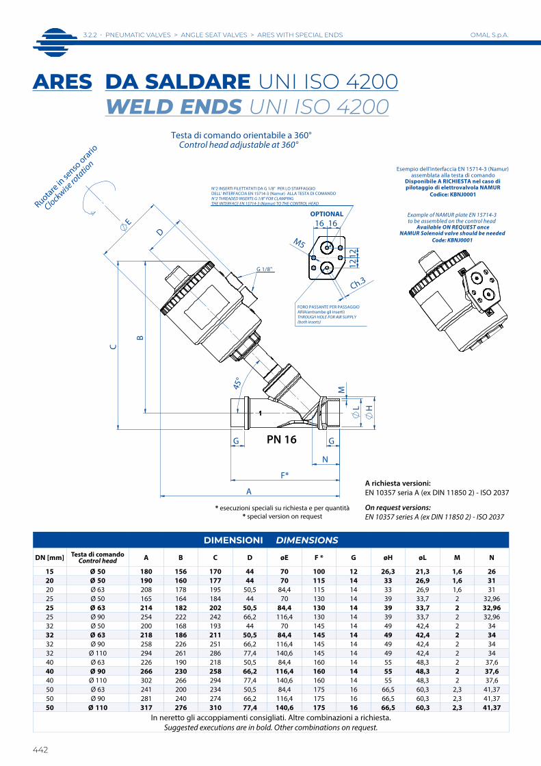
DIMENSIONI DIMENSIONS
DN [mm] Testa di comandoControl head A B C D øE F * G øH øL M N
15 Ø 50 180 156 170 44 70 100 12 26,3 21,3 1,6 2620 Ø 50 190 160 177 44 70 115 14 33 26,9 1,6 3120 Ø 63 208 178 195 50,5 84,4 115 14 33 26,9 1,6 3125 Ø 50 165 164 184 44 70 130 14 39 33,7 2 32,9625 Ø 63 214 182 202 50,5 84,4 130 14 39 33,7 2 32,9625 Ø 90 254 222 242 66,2 116,4 130 14 39 33,7 2 32,9632 Ø 50 200 168 193 44 70 145 14 49 42,4 2 3432 Ø 63 218 186 211 50,5 84,4 145 14 49 42,4 2 3432 Ø 90 258 226 251 66,2 116,4 145 14 49 42,4 2 3432 Ø 110 294 261 286 77,4 140,6 145 14 49 42,4 2 3440 Ø 63 226 190 218 50,5 84,4 160 14 55 48,3 2 37,640 Ø 90 266 230 258 66,2 116,4 160 14 55 48,3 2 37,640 Ø 110 302 266 294 77,4 140,6 160 14 55 48,3 2 37,650 Ø 63 241 200 234 50,5 84,4 175 16 66,5 60,3 2,3 41,3750 Ø 90 281 240 274 66,2 116,4 175 16 66,5 60,3 2,3 41,3750 Ø 110 317 276 310 77,4 140,6 175 16 66,5 60,3 2,3 41,37
In neretto gli accoppiamenti consigliati. Altre combinazioni a richiesta. Suggested executions are in bold. Other combinations on request.
ARES DA SALDARE UNI ISO 4200 WELD ENDS UNI ISO 4200
A richiesta versioni:EN 10357 seria A (ex DIN 11850 2) - ISO 2037
On request versions:EN 10357 series A (ex DIN 11850 2) - ISO 2037
B
45°
D
A
L
N
C
Ruotare in se
nso orario
Clockwise
rotatio
n
G
H
M
G
F*
E
OPTIONAL
N°2 INSERTI FILETTATATI DA G 1/8" PER LO STAFFAGGIODELL' INTERFACCIA EN 15714-3 (Namur) ALLA TESTA DI COMANDON°2 THREADED INSERTS G 1/8" FOR CLAMPINGTHE INTERFACE EN 15714-3 (Namur) TO THE CONTROL HEAD
FORO PASSANTE PER PASSAGGIOARIA(entrambe gli inserti)THROUGH HOLE FOR AIR SUPPLY(both inserts)
12
12
M5
16 16
Ch.3
Testa di comando orientabile a 360°Control head adjustable at 360°
G 1/8"
Esempio dell'interfaccia EN 15714-3 (Namur)assemblata alla testa di comando
Disponibile A RICHIESTA nel caso dipilotaggio di elettrovalvola NAMUR
Codice: KBNJ0001
Example of NAMUR plate EN 15714-3to be assembled on the control head
Available ON REQUEST onceNAMUR Solenoid valve should be needed
Code: KBNJ0001
PN 16

ARES
ATT
ACCH
I SPE
CIAL
IA
RES
SP
ECIA
L EN
DS
3.2.2 • PNEUMATIC VALVES > ANGLE SEAT VALVES > ARES WITH SPECIAL ENDS
443
OMAL S.p.A.
diagramma 1diagram 1
testa headØ40-Ø50
diagramma 3diagram 3
testa headØ90
diagramma 4diagram 4
testa headØ110
diagramma 2diagram 2
testa headØ63
Pressione di comando Control pressure bar
CON INGRESSO DEL FLUIDO SOTTO L'OTTURATORE WITH THE FLOW FROM BELOW THE PLUG
DN [mm]CODICE
CODECF3M
Kvm3/h
Ø Testa comandoØ Control head
P comando barP control barMin Max
P intercettataP operating∆P max. bar
Peso WeightKg.
KIT OTTURATORE DI RICAMBIO
PLUG SPARE KIT
KIT TESTA DI RICAMBIO
HEAD SPARE KIT
15 J4SPG1694 5,7 50 4 10 16 1 KGJP1003 J4SPG16R420 J4SPG1695 10,5 50 4 10 10 1,2 KGJP1005 J4SPG16R520 J4SPG1895 10,8 63 4 10 16 1,2 KGJP1005 J4SPG18R525 J4SPG1896 20 63 4 10 11 1,6 KGJP1006 J4SPG18R625 J4SPG2196 20 90 4 8 16 1,7 KGJP1106 J4SPG21R632 J4SPG2197 29 90 4 8 14 3 KGJP1107 J4SPG21R740 J4SPG2198 46 90 4 8 11 3,4 KGJP1108 J4SPG21R840 J4SPG2398 46,5 110 4 8 16 4 KGJP1108 J4SPG23R850 J4SPG2399 67 110 4 8 10 5,8 KGJP1109 J4SPG23R9
Il kit testa di ricambio comprende tutto l’articolo meno il corpo valvola. The “piloting head replacement Kit” includes the complete item without the valve body only.
ø40: aria 0,031 dm3/cilcloø50: aria 0,051 dm3/cilclo
ø40: air 0,031 dm3/cycleø50: air 0,051 dm3/cycle
aria 0,108 dm3/cilcloair 0,108 dm3/cycle
aria 0,505 dm3/cilcloair 0,505 dm3/cycle
aria 0,238 dm3/cilcloair 0,238 dm3/cycle
ARES DA SALDARE WELD ENDSN.C. Normalmente Chiusa bidirezionale (Con ingresso sotto l’otturatore si evita il colpo d’ariete).N.C. Normally Closed bidirectional (With the flow coming from below the plug you avoid water hammering).
Nei diagrammi le linee tratteggiate indicano le versioni disponibili a richiesta. In the diagrams, the dash lines indicate versions available on request.
CON INGRESSO DEL FLUIDO SOPRA L'OTTURATORE WITH THE FLOW FROM ABOVE THE PLUG
∆p b
ar∆p
bar
∆p b
ar∆p
bar
Pressione di comando Control pressure bar
Pressione di comando Control pressure bar
Pressione di comando Control pressure bar
Pressione di comando Control pressure bar
1 2 3 4 5 6 7 8 9 10
3/4"
0
3/8"
-1/2
"
3/8"
-1/2
"
3/4"
50
40
40
50
6
14
12
10
8
4
2
16
1 2 3 4 5 6 7 8
1" 1"1/
4
1"1/
2
6
14
12
10
8
0
4
2
16
0
3/4"
1"
1 2 3 4 5 6 7 8 9 10
6
14
12
10
8
4
2
16
1 2 3 4 5 6 7 8
1"1/
22"
16
14
12
10
8
6
4
2
0

3.2.2 • PNEUMATIC VALVES > ANGLE SEAT VALVES > ARES WITH SPECIAL ENDS
444
OMAL S.p.A.
DN [mm]CODICE
CODECF3M
Kvm3/h
Ø Testa coman-do
Ø Control head
P comando barP control barMin Max
P intercettataP operating∆P max. bar
Peso WeightKg.
KIT OTTURATORE DI RICAMBIO
PLUG SPARE KIT
KIT TESTA DI RICAMBIO
HEAD SPARE KIT15 J4CPG1694 5,7 50 1,8 10 diagram n° 5 1 KGJP1003 J4CPG16R420 J4CPG1695 10,5 50 1,8 10 diagram n° 5 1,2 KGJP1005 J4CPG16R525 J4CPG1896 20 63 1,8 10 diagram n° 6 1,6 KGJP1006 J4CPG18R632 J4CPG2197 29 90 1,8 8 diagram n° 7 3 KGJP1107 J4CPG21R740 J4CPG2198 46 90 1,8 8 diagram n° 7 3,7 KGJP1108 J4CPG21R850 J4CPG2199 59 90 1,8 8 diagram n° 7 4,4 KGJP1109 J4CPG21R940 J4CPG2398 46,5 110 1,8 8 diagram n° 8 4,6 KGJP1108 J4CPG23R850 J4CPG2399 67 110 1,8 8 diagram n° 8 5,6 KGJP1109 J4CPG23R9
Il kit testa di ricambio comprende tutto l’articolo meno il corpo valvola. The “piloting head replacement Kit” includes the complete item without the valve body only.
diagramma 6diagram 6
testa headØ63
diagramma 5diagram 5
testa headØ40-Ø50
diagramma 7diagram 7
testa headØ90
diagramma 8diagram 8
testa headØ110
ø40: aria 0,031 dm3/cilcloø50: aria 0,051 dm3/cilclo
ø40: air 0,031 dm3/cycleø50: air 0,051 dm3/cycle
aria 0,108 dm3/cilcloair 0,108 dm3/cycle
aria 0,505 dm3/cilcloair 0,505 dm3/cycle
aria 0,238 dm3/cilcloair 0,238 dm3/cycle
ARES DA SALDARE WELD ENDSN.C. Normalmente Chiusa con ingresso sopra l’otturatore N.C. Normally Closed with the flow from above the plug
Nei diagrammi le linee tratteggiate indicano le versioni disponibili a richiesta. In the diagrams, the dash lines indicate versions available on request.
∆p b
ar∆p
bar
∆p b
ar∆p
bar
Pressione di comando Control pressure bar
Pressione di comando Control pressure bar
Pressione di comando Control pressure bar
Pressione di comando Control pressure bar
3/8"
-1/2
"
1 2 3 4 5 6 7 8 9 10
6
3/4"
3/8"
-1/2
"
1" 3/4"
50 50
40
50 40 50 1"1/
4
14
12
10
8
0
4
2
16
1 2 3 4 5 6 7 80
1"1/
4
1"1/
2
2"1"
8
10
12
14
16
2
4
6
3/4"
1"
1"1/
22"
1"1/
4
1 2 3 4 5 6 7 8 9 10
16
14
12
10
8
6
4
2
0
14
12
10
8
16
4
2
1 2 3 4 5 6 7 80
2"
6
1"1/
2

ARES
ATT
ACCH
I SPE
CIAL
IA
RES
SP
ECIA
L EN
DS
3.2.2 • PNEUMATIC VALVES > ANGLE SEAT VALVES > ARES WITH SPECIAL ENDS
445
OMAL S.p.A.
DN [mm]CODICE
CODECF3M
Kvm3/h
Ø Testa comandoØ Control head
P comando barP control barMin Max
P intercettataP operating∆P max. bar
Peso WeightKg.
KIT OTTURATORE DI RICAMBIO
PLUG SPARE KIT
KIT TESTA DI RICAMBIO
HEAD SPARE KIT
15 J4APG1694 5,7 50 2,8 10 diagram n° 9 1 KGJP1003 J4APG16R420 J4APG1695 10,5 50 2,8 10 diagram n° 9 1,2 KGJP1005 J4APG16R525 J4APG1896 20 63 3,2 10 diagram n° 10 1,6 KGJP1006 J4APG18R632 J4APG1897 28,5 63 3,2 10 diagram n° 10 2 KGJP1007 J4APG18R740 J4APG2198 46 90 2 8 diagram n° 11 3,7 KGJP1108 J4APG21R850 J4APG2399 67 110 2,2 8 diagram n° 12 5,6 KGJP1109 J4APG23R9
Il kit testa di ricambio comprende tutto l’articolo meno il corpo valvola. The “piloting head replacement Kit” includes the complete item without the valve body only.
diagramma 9diagram 9
testa headØ50
diagramma 11diagram 11
testa headØ90
diagramma 12diagram 12
testa headØ110
diagramma 10diagram 10
testa headØ63
aria 0,089 dm3/cilcloair 0,089 dm3/cycle aria 0,194 dm3/cilclo
air 0,194 dm3/cycle
aria 1,08 dm3/cilcloair 1,08 dm3/cycle
aria 0,499 dm3/cilcloair 0,499 dm3/cycle
ARES DA SALDARE WELD ENDSN.A. Normalmente Aperta con ingresso sotto l’otturatore N.O. Normally Open with flow from below the plug
Nei diagrammi le linee tratteggiate indicano le versioni disponibili a richiesta. In the diagrams, the dash lines indicate versions available on request.
∆p b
ar∆p
bar
∆p b
ar∆p
bar
Pressione di comando Control pressure bar
Pressione di comando Control pressure bar
Pressione di comando Control pressure bar
Pressione di comando Control pressure bar
3/4"
1"3/8"
-1/2
"
2
0
8
10
12
14
16
4
6
1"1/
4
1 2 3 4 5 6 7 8 9 10
1 2 3 4 5 6 7 8
1" 1"1/
2
1"1/
4
2"
0
14
12
10
8
16
4
2
6
16
3/4"
1" 1"1/
4
1"1/
2
0 1 2 3 4 5 6 7 8 9 10
6
14
12
10
8
4
2
1 2 3 4 5 6 7 8
2"1"1/
2
1"1/
4
0
4
8
2
6
14
12
10
16
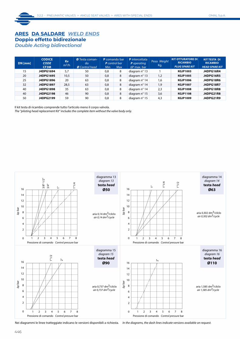
3.2.2 • PNEUMATIC VALVES > ANGLE SEAT VALVES > ARES WITH SPECIAL ENDS
446
OMAL S.p.A.
DN [mm]CODICE
CODECF3M
Kvm3/h
Ø Testa coman-do
Ø Control head
P comando barP control barMin Max
P intercettataP operating∆P max. bar
Peso WeightKg.
KIT OTTURATORE DI RICAMBIO
PLUG SPARE KIT
KIT TESTA DI RICAMBIO
HEAD SPARE KIT
15 J4DPG1694 5,7 50 0,8 8 diagram n° 13 1 KGJP1003 J4DPG16R420 J4DPG1695 10,5 50 0,8 8 diagram n° 13 1,2 KGJP1005 J4DPG16R525 J4DPG1896 20 63 0,8 8 diagram n° 14 1,6 KGJP1006 J4DPG18R632 J4DPG1897 28,5 63 0,8 8 diagram n° 14 1,9 KGJP1007 J4DPG18R740 J4DPG1898 35 63 0,8 8 diagram n° 14 2,3 KGJP1008 J4DPG18R840 J4DPG2198 46 90 0,8 8 diagram n° 15 3,6 KGJP1108 J4DPG21R850 J4DPG2199 59 90 0,8 8 diagram n° 15 4,3 KGJP1009 J4DPG21R9
Il kit testa di ricambio comprende tutto l’articolo meno il corpo valvola. The “piloting head replacement Kit” includes the complete item without the valve body only.
diagramma 13diagram 13
testa headØ50
diagramma 15diagram 15
testa headØ90
diagramma 16diagram 16
testa headØ110
diagramma 14diagram 14
testa headØ63
aria 0,14 dm3/cilcloair 0,14 dm3/cycle
aria 0,302 dm3/cilcloair 0,302 dm3/cycle
aria 1,585 dm3/cilcloair 1,585 dm3/cycle
aria 0,737 dm3/cilcloair 0,737 dm3/cycle
ARES DA SALDARE WELD ENDSDoppio effetto bidirezionale Double Acting bidirectional
Nei diagrammi le linee tratteggiate indicano le versioni disponibili a richiesta. In the diagrams, the dash lines indicate versions available on request.
∆p b
ar∆p
bar
∆p b
ar∆p
bar
Pressione di comando Control pressure bar
Pressione di comando Control pressure bar
Pressione di comando Control pressure bar
Pressione di comando Control pressure bar
1"
1 2 3 4 5 6 7 8
3/4"
3/8"
-1/2
"
1"1/
4
16
14
12
10
8
6
4
2
0
1 2 3 4 5 6 7 80
6
1"1/
2
2"
16
4
12
14
2
8
10
14
16
1 2 3 4 5 6 7 8
1" 1"1/
4
1"1/
2
2
6
8
10
12
4
0
1 2 3 4 5 6 7 8
2"
0
8
10
12
14
16
2
4
6

ARES
ATT
ACCH
I SPE
CIAL
IA
RES
SP
ECIA
L EN
DS
3.2.2 • PNEUMATIC VALVES > ANGLE SEAT VALVES > ARES WITH SPECIAL ENDS
447
OMAL S.p.A.

3.2.2 • PNEUMATIC VALVES > ANGLE SEAT VALVES > ARES WITH SPECIAL ENDS
448
OMAL S.p.A.
Pressione di utilizzo da 0 a 16 bar (vapore a 180°C da 0 a 10 bar) in funzione della misura e della versione scelta (vedi pagine V2.13-V2.14-V2.15-V2.16 del presente catalogo)
Pressure from 0 to 16 bar (steam from 180°C, from 0 to 10 bar) depending on the size and model chosen (see catalog pag. V2.13-V2.14-V2.15-V2.16)
DIMENSIONI DIMENSIONSCLAMP
SizeTesta di comando
Control headPassaggioBore (mm) A B C D øE F * øG øH øL M
1/2” Ø 50 9,5(*) 179 156 168,6 44 70 88,9 25,2 19 9,5 223/4” Ø 50 15 181,5 156 168,6 44 70 101,6 25,2 19 15,8 22
1” Ø 50 20 189,3 160 185,3 44 70 114,3 50,5 32 22,2 43,51” Ø 63 20 207,3 178 203,3 50,5 84,4 114,3 50,5 23 22,2 43,5
1”1/2 Ø 63 32 214,6 186 211,3 50,5 84,4 139,7 50,5 38 34,9 43,51”1/2 Ø 90 32 254,6 226 251,3 66,2 116,4 139,7 50,5 38 34,9 43,51”1/2 Ø 110 32 290,6 261 286,3 77,4 140,6 139,7 50,5 38 34,9 43,5
2” Ø 63 40 224,7 190 222 50,5 84,4 158,8 64 54 47,6 56,52” Ø 90 40 264,7 230 262 66,2 116,4 158,8 64 54 47,6 56,52” Ø 110 40 300,7 266 298 77,4 140,6 158,8 64 54 47,6 56,5
(*) Il passaggio valvola è 15 mm, la riduzione a 9,5 mm è dovuta al passaggio del clamp(*) The valve bore is 15 mm, reduction to 9,5 mm is due to clamp boreIn neretto gli accoppiamenti consigliati. Altre combinazioni a richiesta. Suggested executions are in bold. Other combinations on request.
* esecuzioni speciali su richiesta e per quantità* special version on request
ARES CONNESSIONI CLAMP 3A TRICLAMP ENDS 3A
A richiesta versioni ISO 2852 ISO 2852 version on request
23 ~23 ~
20~
6 ~25 ~
20~
ØG 0-0.19
ØM 0-0.16
ØL` 0.2
1.6
`0.0
7
2.85
`0.
05
ØG` 0.07
ØM` 0.05
ØL 0-0.1
3.6
`0.0
7
2.5
` 0.0
5
0.75
DIMENSIONDIMENSIONE
1/2"-3/4"
DIMENSIONDIMENSIONE
da 1" a 2"
R 0.3
R 2R 0.8
R0.6
R 0.8
R2R0.8
R1.2
B
45°
D
C
M
A
OPTIONAL
N°2 INSERTI FILETTATATI DA G 1/8" PER LO STAFFAGGIODELL' INTERFACCIA EN 15714-3 (Namur) ALLA TESTA DI COMANDON°2 THREADED INSERTS G 1/8" FOR CLAMPINGTHE INTERFACE EN 15714-3 (Namur) TO THE CONTROL HEAD
FORO PASSANTE PER PASSAGGIOARIA(entrambe gli inserti)THROUGH HOLE FOR AIR SUPPLY(both inserts)
12
12
M5
16 16
Ch.3
Ruotare in se
nso orario
Clockwise
rotatio
n
E
F*
Testa di comando orientabile a 360° Control head adjustable at 360°
G 1/8"
Esempio dell'interfaccia EN 15714-3 (Namur)assemblata alla testa di comando
Disponibile A RICHIESTA nel caso dipilotaggio di elettrovalvola NAMUR
Codice: KBNJ0001
Example of NAMUR plate EN 15714-3to be assembled on the control head
Available ON REQUEST onceNAMUR Solenoid valve should be needed
Code: KBNJ0001
PN 16

ARES
ATT
ACCH
I SPE
CIAL
IA
RES
SP
ECIA
L EN
DS
3.2.2 • PNEUMATIC VALVES > ANGLE SEAT VALVES > ARES WITH SPECIAL ENDS
449
OMAL S.p.A.
diagramma 1diagram 1
testa headØ50
diagramma 3diagram 3
testa headØ90
diagramma 4diagram 4
testa headØ110
diagramma 2diagram 2
testa headØ63
(*) Il passaggio valvola è 15 mm, la riduzione a 9,5 mm è dovuta al passaggio del clamp.(*) The valve bore is 15 mm, reduction to 9,5 mm is due to clamp bore.
Misure riferite alla dimensione Clamp. Refer to Clamp size.
CON INGRESSO DEL FLUIDO SOTTO L'OTTURATORE WITH THE FLOW FROM BELOW THE PLUG
CLAMPSIZE
CODICE CODECF3M
PassaggioBore mm
Kvm3/h
Ø Testa comandoØ Control head
P comando barP control barMin Max
P intercettataP operating∆P max. bar
Peso WeightKg.
KIT OTTURATORE DI RICAMBIO
PLUG SPARE KIT
KIT TESTA DI RICAMBIO
HEAD SPARE KIT
1/2” J4SPG16U4 9,5(*) 3,4 50 4 10 16 1 KGJP1003 J4SPG16R43/4” J4SPG16U5 15 5,7 50 4 10 16 1,1 KGJP1004 J4SPG16R4
1” J4SPG16U6 20 10,5 50 4 10 10 1,2 KGJP1005 J4SPG16R51” J4SPG18U6 20 10,5 63 4 10 16 1,4 KGJP1005 J4SPG18R5
1 1/2” J4SPG21U8 32 29 90 4 8 14 3 KGJP1107 J4SPG21R71 1/2” J4SPG23U8 32 29,5 110 4 8 16 3,3 KGJP1107 J4SPG23R7
2” J4SPG21U9 40 46 90 4 8 11 3,4 KGJP1108 J4SPG21R82” J4SPG23U9 40 46,5 110 4 8 16 4 KGJP1108 J4SPG23R8
Il kit testa di ricambio comprende tutto l’articolo meno il corpo valvola. The “piloting head replacement Kit” includes the complete item without the valve body only.
ARES CLAMP 3AN.C. Normalmente Chiusa bidirezionale (Con ingresso sotto l’otturatore si evita il colpo d’ariete).N.C. Normally Closed bidirectional (With the flow coming from below the plug you avoid water hammering).
Nei diagrammi le linee tratteggiate indicano le versioni disponibili a richiesta. In the diagrams, the dash lines indicate versions available on request.
CON INGRESSO DEL FLUIDO SOPRA L'OTTURATORE WITH THE FLOW FROM ABOVE THE PLUG
∆p b
ar∆p
bar
∆p b
ar∆p
bar
Pressione di comando Control pressure bar
Pressione di comando Control pressure bar
Pressione di comando Control pressure bar
Pressione di comando Control pressure bar
1"
1 2 3 4 5 6 7 8 9 10
14
2
10
6
4
1/2"
- 3/4
"
12
0
8
16
0
8
10
12
14
16
2
4
6
1 2 3 4 5 6 7 8
2"1"1/
2
1 2 3 4 5 6 7 8 9 10
1"
16
14
12
10
8
6
4
2
0
1"1/
2
2"
1 2 3 4 5 6 7 8
16
14
12
10
8
6
4
2
0

3.2.2 • PNEUMATIC VALVES > ANGLE SEAT VALVES > ARES WITH SPECIAL ENDS
450
OMAL S.p.A.
(*) Il passaggio valvola è 15 mm, la riduzione a 9,5 mm è dovuta al passaggio del clamp.(*) The valve bore is 15 mm, reduction to 9,5 mm is due to clamp bore.
Misure riferite alla dimensione Clamp. Refer to Clamp size.
diagramma 5diagram 5
testa headØ50
diagramma 7diagram 7
testa headØ90
diagramma 6diagram 6
testa headØ63
diagramma 8diagram 8
testa headØ110
CLAMPSIZE
CODICE CODECF3M
PassaggioBore mm
Kvm3/h
Ø Testa comandoØ Control head
P comando barP control barMin Max
P intercettataP operating∆P max. bar
Peso WeightKg.
KIT OTTURATORE DI RICAMBIO
PLUG SPARE KIT
KIT TESTA DI RICAMBIO
HEAD SPARE KIT
1/2” J4CPG16U4 9,5(*) 3,4 50 1,8 10 diagram n° 5 1 KGJP1003 J4CPG16R43/4” J4CPG16U5 15 5,7 50 1,8 10 diagram n° 5 1,1 KGJP1004 J4CPG16R4
1” J4CPG16U6 20 10,5 50 1,8 10 diagram n° 5 1,2 KGJP1005 J4CPG16R51” J4CPG18U6 20 10,5 63 1,8 10 diagram n° 6 1,4 KGJP1005 J4CPG18R5
1 1/2” J4CPG18U8 32 28,5 63 1,8 10 diagram n° 6 2,6 KGJP1007 J4CPG18R71 1/2” J4CPG21U8 32 29 90 1,8 8 diagram n° 7 3 KGJP1107 J4CPG21R7
2” J4CPG21U9 40 46 90 1,8 8 diagram n° 7 3,7 KGJP1108 J4CPG21R82” J4CPG23U9 40 46,5 110 1,8 8 diagram n° 8 4,6 KGJP1108 J4CPG23R8
Il kit testa di ricambio comprende tutto l’articolo meno il corpo valvola. The “piloting head replacement Kit” includes the complete item without the valve body only.
ARES CLAMP 3AN.C. Normalmente Chiusa con ingresso sopra l’otturatore.N.C. Normally Closed with the flow from above the plug.
Nei diagrammi le linee tratteggiate indicano le versioni disponibili a richiesta. In the diagrams, the dash lines indicate versions available on request.
∆p b
ar∆p
bar
∆p b
ar∆p
bar
Pressione di comando Control pressure bar
Pressione di comando Control pressure bar
Pressione di comando Control pressure bar
Pressione di comando Control pressure bar
1"1/
21/2"
- 3/
4"
1 2 3 4 5 6 7 8 9 10
16
4
12
14
0
6
10
2
8
1"
1 2 3 4 5 6 7 8
1"1/
2
2"16
14
12
10
8
6
4
2
0
1 2 3 4 5 6 7 8 9 10
1"1/
2
1"
2"
16
14
12
10
8
6
4
2
0
1 2 3 4 5 6 7 8
2"
16
14
12
10
8
6
4
2
0

ARES
ATT
ACCH
I SPE
CIAL
IA
RES
SP
ECIA
L EN
DS
3.2.2 • PNEUMATIC VALVES > ANGLE SEAT VALVES > ARES WITH SPECIAL ENDS
451
OMAL S.p.A.
diagramma 9diagram 9
testa headØ50
diagramma 11diagram 11
testa headØ90
diagramma 10diagram 10
testa headØ63
CLAMPSIZE
CODICE CODECF3M
PassaggioBore mm
Kvm3/h
Ø Testa comandoØ Control head
P comando barP control barMin Max
P intercettataP operating∆P max. bar
Peso WeightKg.
KIT OTTURATORE DI RICAMBIO
PLUG SPARE KIT
KIT TESTA DI RICAMBIO
HEAD SPARE KIT
1/2” J4APG16U4 9,5(*) 3,4 50 2,8 10 diagram n° 9 1 KGJP1003 J4APG16R43/4” J4APG16U5 15 5,7 50 2,8 10 diagram n° 9 1,1 KGJP1004 J4APG16R4
1” J4APG16U6 20 10,5 50 2,8 10 diagram n° 9 1,2 KGJP1005 J4APG16R51 1/2” J4APG18U8 32 28,5 63 3,2 10 diagram n° 10 2,6 KGJP1007 J4APG18R7
2” J4APG21U9 40 46 90 2 8 diagram n° 11 3,7 KGJP1108 J4APG21R8
Il kit testa di ricambio comprende tutto l’articolo meno il corpo valvola. The “piloting head replacement Kit” includes the complete item without the valve body only.
ARES CLAMP 3AN.A. Normalmente Aperta con ingresso sotto l’otturatore.N.O. Normally Open with flow from below the plug.
Nei diagrammi le linee tratteggiate indicano le versioni disponibili a richiesta. In the diagrams, the dash lines indicate versions available on request.
(*) Il passaggio valvola è 15 mm, la riduzione a 9,5 mm è dovuta al passaggio del clamp.(*) The valve bore is 15 mm, reduction to 9,5 mm is due to clamp bore.
Misure riferite alla dimensione Clamp. Refer to Clamp size.
∆p b
ar∆p
bar
∆p b
ar
Pressione di comando Control pressure bar
Pressione di comando Control pressure bar
Pressione di comando Control pressure bar
1/2"
- 3/
4"
8
1 2 3 4 5 6 7 8 9 10
16
1"
10
12
14
2
4
6
0
1 2 3 4 5 6 7 8
2"
16
14
12
10
8
6
4
2
0
1"1/
2
10
1 2 3 4 5 6 7 8 9 10
16
1"1/
2
12
14
0
2
4
6
8
1" 2"

3.2.2 • PNEUMATIC VALVES > ANGLE SEAT VALVES > ARES WITH SPECIAL ENDS
452
OMAL S.p.A.
diagramma 13diagram 13
testa headØ50
diagramma 15diagram 15
testa headØ90
diagramma 14diagram 14
testa headØ63
CLAMPSIZE
CODICE CODECF3M
PassaggioBore mm
Kvm3/h
Ø Testa comandoØ Control head
P comando barP control barMin Max
P intercettataP operating∆P max. bar
Peso WeightKg.
KIT OTTURATORE DI RICAMBIO
PLUG SPARE KIT
KIT TESTA DIRICAMBIO
HEAD SPARE KIT
1/2” J4DPG16U4 9,5(*) 3,4 50 0,8 8 diagram n° 13 1 KGJP1003 J4DPG16R43/4” J4DPG16U5 15 5,7 50 0,8 8 diagram n° 13 1,1 KGJP1004 J4DPG16R4
1” J4DPG16U6 20 10,5 50 0,8 8 diagram n° 13 1,2 KGJP1005 J4DPG16R51 1/2” J4DPG18U8 32 28,5 63 0,8 8 diagram n° 14 2 KGJP1007 J4DPG18R7
2” J4DPG18U9 40 35 63 0,8 8 diagram n° 14 2,3 KGJP1008 J4DPG18R82” J4DPG21U9 40 46 90 0,8 8 diagram n° 15 3,6 KGJP1108 J4DPG21R8
Il kit testa di ricambio comprende tutto l’articolo meno il corpo valvola. The “piloting head replacement Kit” includes the complete item without the valve body only.
ARES CLAMP 3ADoppio effetto bidirezionale.Double Acting bidirectional.
Nei diagrammi le linee tratteggiate indicano le versioni disponibili a richiesta. In the diagrams, the dash lines indicate versions available on request.
(*) Il passaggio valvola è 15 mm, la riduzione a 9,5 mm è dovuta al passaggio del clamp.(*) The valve bore is 15 mm, reduction to 9,5 mm is due to clamp bore.
Misure riferite alla dimensione Clamp. Refer to Clamp size.
∆p b
ar∆p
bar
∆p b
ar
Pressione di comando Control pressure bar
Pressione di comando Control pressure bar
Pressione di comando Control pressure bar
1 2 3 4 5 6 7 8
2
1/2"
- 3/
4"
1"
0
16
14
12
10
8
6
4
1 2 3 4 5 6 7 8
2"
16
14
12
10
8
6
4
2
0
1 2 3 4 5 6 7 8
2"1"1/
2
0
2
4
6
8
10
12
16
14

ARES
ATT
ACCH
I SPE
CIAL
IA
RES
SP
ECIA
L EN
DS
3.2.2 • PNEUMATIC VALVES > ANGLE SEAT VALVES > ARES WITH SPECIAL ENDS
453
OMAL S.p.A.

3.2.3 • PNEUMATIC VALVES > ANGLE SEAT VALVES > ARES MANUAL DRIVE
454
OMAL S.p.A.
J4 M0 G 0 - - - YX
Connessioni a richiesta Ends on request0 = Filettate Threaded ends EN 10226-1 Rp (ex ISO 7/1); 4 = Filettate Threaded ends NPT;9 = da saldare weld ends ISO 4200; I = da saldare weld ends ISO 2037; D = da saldare weld ends DIN 11852 2;
6 = flangiate flanged EN 1092-1; A = flangiate flanged ANSI 150 RF;B = flangiate ridotte reduced flanges; T = triclamp ISO 2852; U = triclamp USA 3A.
0 = Manuale Manual drive;B = Manuale con dispositivo di bloccaggio Manual drive with locking device
YX solo per versioni ATEXYX only for ATEX versions
CARATTERISTICHE GENERALI:• Materiale del corpo valvola: A351-CF8M (316 S.S.). • Attacchi valvola: vedi schema di codifica.• Montaggio in ogni posizione: orizzontale, verticale, obliqua.• Gamma disponibile da DN 10 a DN 50.• Disponibile anche versione con dispositivo di bloccaggio.• Configurazione ATEX 2014/34/UE da richiedere in fase d'ordine.• A richiesta: versioni per vuoto e per uso ossigeno.
GENERAL FEATURES:• Body valve material: A351-CF8M (316 S.S.).• Valve ends: see code plan.• Assembling is possible in all positions: upright, flat or angled. • Range available from DN 10 to DN 50.• Locking device version available.• 2014/34/EU ATEX configuration to request at time of order.• On request: versions for vacuum and oxygen service.
FLUIDO INTERCETTATO:• Aria, acqua, alcool, olii, carburanti, soluzioni saline, vapore, ecc..(comun-
que compatibili con A 351 CF8M (316 S.S.) e PTFE).• Pressione di utilizzo da 0 a 25 bar (vapore a 180°C da 0 a 10 bar) in
funzione della versione scelta.• Temperatura da -10°C a +180°C.• Viscosità massima 600 cst (mm2/s).
OPERATING MEDIA:• Air, water, alcohol, oil, petroleum products, saline solutions, steam, etc. (as
long as compatible with A 351 CF8M (316 S.S.) e PTFE).• Pressure from 0 to 25 bar (steam from 180°C, from 0 to 10 bar) depending
on the model chosen.• Temperature from –10°C to 180°C.• Max. viscosity 600 cst (mm2 /s).
ARES MANUALEARES MANUAL DRIVE
SCHEMA DI CODIFICA ARES MANUALIARES MANUAL DRIVE CODE PLAN
PN 25
Misura valvola Valve size
3 = 3/8"4 = 1/2" 4 = DN 155 = 3/4" 5 = DN 206 = 1" 6 = DN 257 = 1" 1/4 7 = DN 328 = 1" 1/2 8 = DN 409 = 2" 9 = DN 50

AR
ES M
AN
UA
LEAR
ES M
ANU
AL D
RIVE
3.2.3 • PNEUMATIC VALVES > ANGLE SEAT VALVES > ARES MANUAL DRIVE
455
OMAL S.p.A.
DIMENSIONI DIMENSIONSDN [mm] G * [inch] øA B C D E F H
15 3/8” 63 138,5 126 169 85 34,5 1215 1/2” 63 138,5 126 169 85 34,5 1520 3/4” 63 148,5 133 176,2 95 34,7 16,325 1” 63 152 133 178,1 105 36,6 19,532 11/4” 100 191,5 168 222,5 120 40,5 1940 11/2” 100 197 170 225 130 41 1850 2” 100 213 180 239,5 150 45,5 20
* A richiesta filetto NPT NPT on request
MATERIALI MATERIALSN° Descrizione Description Materiali Materials1 Corpo valvola Valve body CF8M (316 S.S.)2 Cannotto premistoppa Sleeve CF8M (316 S.S.)3 Stelo Stem 316L S.S.4 Otturatore Plug 316L S.S.5 Guarnizione otturatore Plug seals PTFE6 Manopola Hand grip Tecnoplimero Tecnopolymer7 Premiguarnizione Gland Nut 304 S.S.8 Bussola Bush Lega di alluminio Aluminium Alloy
ARES MANUALE ARES MANUAL DRIVEATTACCHI FILETTATI THREADED VALVE ENDS EN 10226-1 RP (EX ISO 7/1)
F
45°
C
A
D
B
*A richiesta �letto NPT NPT on request
5
8
3
2
1
4
6
7
H G
* - �
lett
atur
a EN
102
26-1
Rp
(ex
ISO
7/1
)
E G
* - E
N 1
0226
-1 R
p (e
x IS
O 7
/1)
thre
aded
PN 25

3.2.3 • PNEUMATIC VALVES > ANGLE SEAT VALVES > ARES MANUAL DRIVE
456
OMAL S.p.A.
DIMENSIONI DIMENSIONSDN [mm] G * [inch] øA B C D E F H
15 3/8” 63 138,5 126 169 85 34,5 1215 1/2” 63 138,5 126 169 85 34,5 1520 3/4” 63 148,5 133 176,2 95 34,7 16,325 1” 63 152 133 178,1 105 36,6 19,532 11/4” 100 191,5 168 222,5 120 40,5 1940 11/2” 100 197 170 225 130 41 1850 2” 100 213 180 239,5 150 45,5 20
* A richiesta filetto NPT NPT on request
MATERIALI MATERIALSN° Descrizione Description Materiali Materials1 Corpo valvola Valve body CF8M2 Cannotto premistoppa Sleeve CF8M3 Stelo Stem 316L S.S.4 Otturatore Plug 316L S.S.5 Guarnizione otturatore Plug seals PTFE6 Manopola Hand grip Tecnoplimero Tecnopolymer7 Ghiera di bloccaggio Locking nut 304 S.S.8 Pinza Pliers Ottone Brass9 Bussola Bush Lega di alluminio Aluminium Alloy
10 Premiguarnizione Gland Nut 304 S.S.11 Ogiva Ogive 304 S.S.
ARES MANUALE CON DISPOSITIVO DI BLOCCAGGIO ARES MANUAL DRIVE WITH BLOCKING DEVICEATTACCHI FILETTATI THREADED VALVE ENDS EN 10226-1 RP (EX ISO 7/1)
F
C
B
45°
A
D
*a richiesta �letto NPT NPT on request
1
5
2
11
4
3
78
6
10
9
H
E
G*
- �le
ttat
ura
EN 1
0226
-1 R
p (e
x IS
O 7
/1)
G* -
EN
102
26-1
Rp
(ex
ISO
7/1
) th
read
edPN 25

AR
ES M
AN
UA
LEAR
ES M
ANU
AL D
RIVE
3.2.3 • PNEUMATIC VALVES > ANGLE SEAT VALVES > ARES MANUAL DRIVE
457
OMAL S.p.A.

3.2.4 • PNEUMATIC VALVES > ANGLE SEAT VALVES > ZEUS
458
OMAL S.p.A.
ZEUSVALVOLA INCLINATAANGLE SEAT VALVE
2
7
6
5
4
3
1

ZEU
S
3.2.4 • PNEUMATIC VALVES > ANGLE SEAT VALVES > ZEUS
459
OMAL S.p.A.
FEATURES & BENEFITS
1Guarnizione posizionata nel cilindro anziché sul pistone
Seal placed in the cylinder rather than on the piston
Si ottiene una maggiore corsa dell'attuatore e dell'otturatore ad esso collegato garantendo grandi aperture del passaggio sulla sede (minor perdita di carico)
Longer stroke of the actuator and shutter will be achieved, granting higher flow rate (less flow loss)
Minor usura della guarnizione
Less wear of the seal
2Inserti della testa di comando in 303 S.S..
Piloting head inserts in 303 S.S..
Aumenta considerevolmente la resistenza alla corrosione causata da agenti esterni.
Increases considerably the corrosion resistance caused by external agents.
3
Dal DN63 pistone metallico con rivestimento in NICHEL-CHIMICO (10-15 micron)
Starting from DN63 metal piston with CHEMICAL NICKEL coating (10-15 micron)
Si riduce l'usura del pistone grazie al raggiungimento di una maggior durezza superficiale(700-750 HV)
Reduces the wear of the piston due to the achievement of a greater surface hardness (700-750 HV)
4Guarnizioni precaricate da molla
Seals pre-loaded by spring
Garantiscono il recupero dei giochi dovuti all'usura causata dallo scor-rimento lineare dell'albero evitando perdite vero l'esterno
Guarantee of the recovery of the gap due to the wear caused by the sliding of the shaft avoiding leakage towards the outside part.
Consentono di mantenere energizzati le guarnizioni "chevron" (a V) compensandone le variazioni dimensionali anche a fronte di notevoli escursioni termiche
Allow to maintain energized the "chevron" seals (V) compensating the dimensional changes even in case of huge temperature excursions
5
Guarnizioni tipo "chevron" (a "v") con 4 guarnizioni nella parte inferiore
CHEVRON seals (V shape) with 4 seals in the lower part
Si garantisce una perfetta tenuta anche dopo un numero elevato di cicli
It ensures a perfect tightness even after a high number of cycles
6Albero rullato
Rolled shaft
Minor usura delle guarnizioni grazie alla bassa rugosità (0,1 micron Ra) dell'albero che facilita lo scorrimento
Less wear of the seals due to the low roughness (0,1 micron Ra) which facilitate the sliding of the shaft
7Otturatore oscillante/autoallineante
Oscillating / self-aligning shutter
Si adatta perfettamente alla sede sul corpo valvola garantendo una massima tenuta
It fits perfectly to the valve body ensuring the maximum tightness
Certificato ATEX
ATEX Certificate
Ne consente l'installazione in presenza di ambiente potenzialmente esplosivo
Installation is allowed in a potential explosive environment
Certificato PED
PED Certificate
Piena conformità alle norme di sicurezza europee per i dispositivi in pressione
Full compliance with European Safety Standards for Pressure Equipment

3.2.4 • PNEUMATIC VALVES > ANGLE SEAT VALVES > ZEUS
460
OMAL S.p.A.
ZEUS
DIMENSIONI DIMENSIONS
DN [mm] G * [inch] Attuatore Actuator A B C D øE F ch. L H
15 3/8” Ø 50 166 143 156,5 44 70 65 27 1215 1/2” Ø 50 166 143 156,5 44 70 65 27 1320 3/4” Ø 50 174 148,5 165 44 70 75 33 14,320 3/4” Ø 63 192,5 167 183,5 50,5 84,4 75 33 14,325 1” Ø 50 --- 175,5 --- --- --- --- --- 17,525 1” Ø 63 206 225 196 50,5 84,4 90 41 17,525 1” Ø 90 254,5 180 245,5 66,2 116,4 90 41 1932 1 1/4” Ø 50 --- 231 --- --- --- --- --- 1932 1 1/4” Ø 63 215 235 205 50,5 84,4 110 50 1832 1 1/4” Ø 90 267 271 256 66,2 116,4 110 50 1832 1 1/4” Ø 110 --- 240 --- --- --- --- --- 2040 1 1/2” Ø 63 --- 276 --- --- --- --- --- 2040 1 1/2” Ø 90 270 264 66,2 116,4 120 5840 1 1/2” Ø 110 306 300 77,4 140,6 120 5850 2” Ø 63 --- --- --- --- --- ---50 2” Ø 90 280 275 66,2 116,4 150 7050 2” Ø 110 316 311 77,4 140,6 150 70
* A richiesta la versione con filettatura NPT On request NPT-threading
B
C
45°
H
G -
�let
tatu
ra IS
O 2
28/1
A
D
G 1/8"
Testa di comando orientabile a 360° Control head adjustable at 360°
Ruotare in se
nso orario
Clockwise
rotatio
n
F
G -
ISO
228
/1 T
hrea
ding
E
Ch.L
N°2 INSERTI FILETTATATI DA G 1/8" PER LO STAFFAGGIODELL' INTERFACCIA EN 15714-3 (Namur) ALLA TESTA DI COMANDON°2 THREADED INSERTS G 1/8" FOR CLAMPINGTHE INTERFACE EN 15714-3 (Namur) TO THE CONTROL HEAD
OPTIONAL
M5
12
16 16
12
Ch. 3
FORO PASSANTE PER PASSAGGIOARIA(entrambe gli inserti)THROUGH HOLE FOR AIR SUPPLY(both inserts)
Esempio dell'interfaccia EN 15714-3 (Namur)assemblata alla testa di comando
Disponibile A RICHIESTA nel caso dipilotaggio di elettrovalvola NAMUR
Codice: KBNJ0001
Example of NAMUR plate EN 15714-3to be assembled on the control head
Available ON REQUEST onceNAMUR Solenoid valve should be needed
Code: KBNJ0001

ZEU
S
3.2.4 • PNEUMATIC VALVES > ANGLE SEAT VALVES > ZEUS
461
OMAL S.p.A.
ZEUS
30
25
20
15
10
5
0-20 -10 0 10 20 30 40 50 60 70 80 90
°C
100 110 120 130 140 150 160 170 180 190 200
bar
DIAGRAMMA PRESSIONE/TEMPERATURA TEMPERATURE/PRESSURE DIAGRAM
N° MATERIALI MATERIALS1 Corpo valvola Valve body Bronzo Bronze CuSn5Zn5Pb5-B2 Cannotto premistoppa Sleeve Ottone EN 12165 CW617N Brass EN 12165 CW617N3 Stelo Stem 316L S.S.4* Guarnizioni stelo Stem seals PTFE-CF5* Guarnizione corpo Body seal GRAPHITE6 Otturatore Plug 316L S.S.7 Guarnizione otturatore Plug seal PTFE8 Testa di comando Actuator cylinder Poliammide PA 66 + GF 30%9 Pistone Piston Ottone nichel chimico Brass chem-nickel (PBT + GF 20% testa/head ø50)10 Inserti di pilotaggio Threading inserts 303 S.S.* Per applicazioni alta purezza sono disponibili guarnizioni stelo in PTFE vergine e guarnizione corpo in Peek For high purity application are allowable stem seals in virgin PTFE and body seals in Peek
DIAGRAMMA T AMBIENTE/T FLUIDO INTERCETTABILE AMBIENT TEMPERATURE/MEDIA TEMPERATURE DIAGRAM
50
60
70
20
30
40
100 110 120 130 140 150 160 170 180 190 200
ø40
ø50
ø63
°C Temperatura del fluido Media temperature
°C T
empe
ratu
ra a
mbi
ente
Am
bien
t tem
pera
ture

3.2.4 • PNEUMATIC VALVES > ANGLE SEAT VALVES > ZEUS
462
OMAL S.p.A.
DIMENSIONI DIMENSIONSVersione in Bronzo Bronze version
DN [mm]
G * [inch]
AttuatoreActuator A B C H 39 ø61 F ch. L
15 3/8” Ø 40* 144 120,5 134 12 39 61 65 2715 1/2” Ø 40* 144 120,5 134 13 39 61 65 2720 3/4” Ø 40* 151 127,5 142,5 14,3 39 61 75 33
* A richiesta la versione con filettatura NPT On request NPT-threading
45°
B
C
39
H
G -
File
ttat
ura
ISO
228
/1
A
G 1/8"
G 1/8"
F
Ruotare in se
nso orario
Clockwise ro
tation
G -
ISO
228
/1 T
read
ing
Testa di comando orientabile a 360° Control head adjustablr al 360°
61
Ch. L
ZEUS TESTA ∅40 HEAD ∅40

ZEU
S
3.2.4 • PNEUMATIC VALVES > ANGLE SEAT VALVES > ZEUS
463
OMAL S.p.A.
30
25
20
15
10
5
0-20 -10 0 10 20 30 40 50 60 70 80 90
°C
100 110 120 130 140 150 160 170 180 190 200
bar
ZEUS TESTA ∅40 HEAD ∅40
10
8
9
7
1
6
3
4
2
5
DIAGRAMMA PRESSIONE/TEMPERATURATEMPERATURE/PRESSURE DIAGRAM
N° MATERIALI MATERIALS1 Corpo valvola Valve body Bronzo Bronze CuSn5Zn5Pb5-B2 Cannotto premistoppa Sleeve Ottone EN 12165 CW617N Brass EN 12165 CW617N3 Stelo Stem 316L S.S.4* Guarnizioni stelo Stem seals PTFE-CF5* Guarnizione corpo Body seal GRAPHITE6 Otturatore Plug 316L S.S.7 Guarnizione otturatore Plug seal PTFE8 Testa di comando Actuator cylinder Poliammide PA 66 + GF 30%9 Pistone Piston PBT + GF 20%10 Inserti di pilotaggio Threading inserts 303 S.S.* Per applicazioni alta purezza sono disponibili guarnizioni stelo in PTFE vergine e guarnizione corpo in Peek For high purity application are allowable stem seals in virgin PTFE and body seals in Peek
DIAGRAMMA T AMBIENTE/T FLUIDO INTERCETTABILE AMBIENT TEMPERATURE/MEDIA TEMPERATURE DIAGRAM
50
60
70
20
30
40
100 110 120 130 140 150 160 170 180 190 200
ø40
°C Temperatura del fluido Media temperature
°C T
empe
ratu
ra a
mbi
ente
Am
bien
t tem
pera
ture

3.2.4 • PNEUMATIC VALVES > ANGLE SEAT VALVES > ZEUS
464
OMAL S.p.A.
diagramma 1diagram 1
testa headØ40-Ø50
diagramma 3diagram 3
testa headØ90
diagramma 4diagram 4
testa headØ110
diagramma 2diagram 2
testa headØ63
ø40: aria 0,031 dm3/cilcloø50: aria 0,051 dm3/cilclo
ø40: air 0,031 dm3/cycleø50: air 0,051 dm3/cycle
aria 0,108 dm3/cilcloair 0,108 dm3/cycle
aria 0,505 dm3/cilcloair 0,505 dm3/cycle
aria 0,238 dm3/cilcloair 0,238 dm3/cycle
CON INGRESSO DEL FLUIDO SOTTO L'OTTURATORE WITH THE FLOW FROM BELOW THE PLUG
DN [mm]
FilettaturaThreading
CODICE BRONZO
CODE BRONZE
Kvm3/h
Ø Testa comando
Ø Control head
P comando barP control barMin Max
P intercettataP operating∆P max. bar
PesoWeight
Kg.
KIT OTTURATORE DI RICAMBIO
PLUG SPARE KIT
KIT TESTA DI RICAMBIO
HEAD SPARE KIT
15 3/8” J9SPG1403 4,5 40 4,2 10 16 1,1 KGJP2303 J9SPG14R315 3/8” J9SPG1603 4,9 50 4 10 16 1,1 KGJP2003 J9SPG16R315 1/2” J9SPG1404 5,3 40 4,2 10 16 1 KGJP2303 J9SPG14R415 1/2” J9SPG1604 5,7 50 4 10 16 1 KGJP2003 J9SPG16R420 3/4” J9SPG1405 9,2 40 4,2 10 8 1,2 KGJP2305 J9SPG14R520 3/4” J9SPG1605 10,5 50 4 10 10 1,2 KGJP2005 J9SPG16R520 3/4” J9SPG1805 10,8 63 4 10 16 1,2 KGJP2005 J9SPG18R525 1” J9SPG1806 20 63 4 10 11 1,6 KGJP2005 J9SPG18R625 1” J9SPG2106 20 90 4 8 16 1,7 KGJP2106 J9SPG21R632 1 1/4” J9SPG2107 29 90 4 8 14 3 KGJP2107 J9SPG21R740 1 1/2” J9SPG2108 46 90 4 8 11 3,4 KGJP2108 J9SPG21R840 1 1/2” J9SPG2308 46,5 110 4 8 16 4 KGJP2108 J9SPG23R850 2” J9SPG2309 67 110 4 8 10 5,8 KGJP2109 J9SPG23R9
Il kit testa di ricambio comprende tutto l’articolo meno il corpo valvola. The “piloting head replacement Kit” includes the complete item without the valve body only.
Il kit otturatore di ricambio comprende l'otturatore e le guarnizioni necessarie.The shutter “replacement Kit” includes the shutter and the necessary seals.
ZEUSN.C. Normalmente Chiusa bidirezionale (Con ingresso sotto l’otturatore si evita il colpo d’ariete).N.C. Normally Closed bidirectional (With the flow coming from below the plug you avoid water hammering).
Nei diagrammi le linee tratteggiate indicano le versioni disponibili a richiesta. In the diagrams, the dash lines indicate versions available on request.
CON INGRESSO DEL FLUIDO SOPRA L'OTTURATORE WITH THE FLOW FROM ABOVE THE PLUG
∆p b
ar∆p
bar
∆p b
ar∆p
bar
Pressione di comando Control pressure bar
Pressione di comando Control pressure bar
Pressione di comando Control pressure bar
Pressione di comando Control pressure bar
1 2 3 4 5 6 7 8 9 10
3/4"
0
3/8"
-1/2
"
3/8"
-1/2
"
3/4"
50
40
40
50
6
14
12
10
8
4
2
16
1 2 3 4 5 6 7 8
1" 1"1/
4
1"1/
2
6
14
12
10
8
0
4
2
16
0
3/4"
1"
1 2 3 4 5 6 7 8 9 10
6
14
12
10
8
4
2
16
1 2 3 4 5 6 7 8
1"1/
22"
16
14
12
10
8
6
4
2
0

ZEU
S
3.2.4 • PNEUMATIC VALVES > ANGLE SEAT VALVES > ZEUS
465
OMAL S.p.A.
diagramma 6diagram 6
testa headØ63
diagramma 5diagram 5
testa headØ40-Ø50
diagramma 7diagram 7
testa headØ90
diagramma 8diagram 8
testa headØ110
ø40: aria 0,031 dm3/cilcloø50: aria 0,051 dm3/cilclo
ø40: air 0,031 dm3/cycleø50: air 0,051 dm3/cycle
aria 0,108 dm3/cilcloair 0,108 dm3/cycle
aria 0,505 dm3/cilcloair 0,505 dm3/cycle
aria 0,238 dm3/cilcloair 0,238 dm3/cycle
DN [mm]
FilettaturaThreading
CODICE BRONZO
CODE BRONZE
Kvm3/h
Ø Testa comando
Ø Control head
P comando barP control barMin Max
P intercettataP operating∆P max. bar
PesoWeight
Kg.
KIT OTTURATORE DI RICAMBIO
PLUG SPARE KIT
KIT TESTA DI RICAMBIO
HEAD SPARE KIT
15 3/8” J9CPG1403 4,5 40 2,5 10 diagram n° 5 1 KGJP2303 J9CPG14R315 3/8” J9CPG1603 4,9 50 1,8 10 diagram n° 5 1 KGJP2003 J9CPG16R315 1/2” J9CPG1404 5,3 40 2,,5 10 diagram n° 5 1 KGJP2303 J9CPG14R415 1/2” J9CPG1604 5,7 50 1,8 10 diagram n° 5 1 KGJP2003 J9CPG16R420 3/4” J9CPG1405 9,2 40 2,5 10 diagram n° 5 1,2 KGJP2305 J9CPG14R520 3/4” J9CPG1605 10,5 50 1,8 10 diagram n° 5 1,2 KGJP2005 J9CPG16R525 1” J9CPG1806 20 63 1,8 10 diagram n° 6 1,6 KGJP2006 J9CPG18R632 1 1/4” J9CPG2107 29 90 1,8 8 diagram n° 7 3 KGJP2107 J9CPG21R740 1 1/2” J9CPG2108 46 90 1,8 8 diagram n° 7 3,7 KGJP2108 J9CPG21R840 1 1/2” J9CPG2308 46,5 110 1,8 8 diagram n° 8 4,6 KGJP2108 J9CPG23R850 2” J9CPG2109 59 90 1,8 8 diagram n° 7 4,4 KGJP2109 J9CPG21R950 2” J9CPG2309 67 110 1,8 8 diagram n° 8 5,6 KGJP2109 J9CPG23R9
Il kit testa di ricambio comprende tutto l’articolo meno il corpo valvola. The “piloting head replacement Kit” includes the complete item without the valve body only.
Il kit otturatore di ricambio comprende l'otturatore e le guarnizioni necessarie.The shutter “replacement Kit” includes the shutter and the necessary seals.
ZEUSN.C. Normalmente Chiusa con ingresso sopra l’otturatore.N.C. Normally Closed with the flow from above the plug.
Nei diagrammi le linee tratteggiate indicano le versioni disponibili a richiesta. In the diagrams, the dash lines indicate versions available on request.
∆p b
ar∆p
bar
∆p b
ar∆p
bar
Pressione di comando Control pressure bar
Pressione di comando Control pressure bar
Pressione di comando Control pressure bar
Pressione di comando Control pressure bar
3/8"
-1/2
"
1 2 3 4 5 6 7 8 9 10
6
3/4"
3/8"
-1/2
"
1" 3/4"
50 50
40
50 40 50 1"1/
4
14
12
10
8
0
4
2
16
1 2 3 4 5 6 7 80
1"1/
4
1"1/
2
2"1"
8
10
12
14
16
2
4
6
3/4"
1"
1"1/
22"
1"1/
4
1 2 3 4 5 6 7 8 9 10
16
14
12
10
8
6
4
2
0
14
12
10
8
16
4
2
1 2 3 4 5 6 7 80
2"
6
1"1/
2

3.2.4 • PNEUMATIC VALVES > ANGLE SEAT VALVES > ZEUS
466
OMAL S.p.A.
diagramma 9diagram 9
testa headØ50
diagramma 11diagram 11
testa headØ90
diagramma 12diagram 12
testa headØ110
diagramma 10diagram 10
testa headØ63
aria 0,089 dm3/cilcloair 0,089 dm3/cycle aria 0,194 dm3/cilclo
air 0,194 dm3/cycle
aria 1,08 dm3/cilcloair 1,08 dm3/cycle
aria 0,499 dm3/cilcloair 0,499 dm3/cycle
DN [mm]
FilettaturaThreading
CODICE BRONZO
CODE BRONZE
Kvm3/h
Ø Testa comando
Ø Control head
P comando barP control barMin Max
P intercettataP operating∆P max. bar
PesoWeight
Kg.
KIT OTTURATORE DI RICAMBIO
PLUG SPARE KIT
KIT TESTA DI RICAMBIO
HEAD SPARE KIT
15 3/8” J9APG1603 4,9 50 2,8 10 diagram n° 9 1 KGJP2003 J9APG16R315 1/2” J9APG1604 5,7 50 2,8 10 diagram n° 9 1 KGJP2003 J9APG16R420 3/4” J9APG1605 10,5 50 2,8 10 diagram n° 9 1,2 KGJP2005 J9APG16R525 1” J9APG1806 20 63 3,2 10 diagram n° 10 1,6 KGJP2006 J9APG18R632 1 1/4” J9APG1807 28,5 63 3,2 10 diagram n° 10 2 KGJP2007 J9APG18R740 1 1/2” J9APG2108 46 90 2 8 diagram n° 11 3,7 KGJP2108 J9APG21R850 2” J9APG2309 67 110 2,2 8 diagram n° 12 5,6 KGJP2109 J9APG23R9
Il kit testa di ricambio comprende tutto l’articolo meno il corpo valvola. The “piloting head replacement Kit” includes the complete item without the valve body only.
Il kit otturatore di ricambio comprende l'otturatore e le guarnizioni necessarie.The shutter “replacement Kit” includes the shutter and the necessary seals.
ZEUSN.A. Normalmente Aperta con ingresso sotto l’otturatore N.O. Normally Open with flow from below the plug
Nei diagrammi le linee tratteggiate indicano le versioni disponibili a richiesta. In the diagrams, the dash lines indicate versions available on request.
∆p b
ar∆p
bar
∆p b
ar∆p
bar
Pressione di comando Control pressure bar
Pressione di comando Control pressure bar
Pressione di comando Control pressure bar
Pressione di comando Control pressure bar
3/4"
1"3/8"
-1/ 2
"
2
0
8
10
12
14
16
4
6
1"1/
4
1 2 3 4 5 6 7 8 9 10
1 2 3 4 5 6 7 8
1" 1"1/
2
1"1/
4
2"
0
14
12
10
8
16
4
2
6
16
3/4"
1" 1"1/
4
1"1/
2
0 1 2 3 4 5 6 7 8 9 10
6
14
12
10
8
4
2
1 2 3 4 5 6 7 8
2"1"1/
2
1"1/
4
0
4
8
2
6
14
12
10
16

ZEU
S
3.2.4 • PNEUMATIC VALVES > ANGLE SEAT VALVES > ZEUS
467
OMAL S.p.A.
diagramma 13diagram 13
testa headØ50
diagramma 15diagram 15
testa headØ90
diagramma 16diagram 16
testa headØ110
diagramma 14diagram 14
testa headØ63
aria 0,14 dm3/cilcloair 0,14 dm3/cycle
aria 0,302 dm3/cilcloair 0,302 dm3/cycle
aria 1,585 dm3/cilcloair 1,585 dm3/cycle
aria 0,737 dm3/cilcloair 0,737 dm3/cycle
DN [mm]
FilettaturaThreading
CODICE BRONZO
CODE BRONZE
Kvm3/h
Ø Testa comando
Ø Control head
P comando barP control barMin Max
P intercettataP operating∆P max. bar
PesoWeight
Kg.
KIT OTTURATORE DI RICAMBIO
PLUG SPARE KIT
KIT TESTA DI RICAMBIO
HEAD SPARE KIT
15 3/8” J9DPG1603 4,9 50 0,8 8 diagram n° 13 1 KGJP2003 J9DPG16R315 1/2” J9DPG1604 5,7 50 0,8 8 diagram n° 13 1 KGJP2003 J9DPG16R420 3/4” J9DPG1605 10,5 50 0,8 8 diagram n° 13 1,2 KGJP2005 J9DPG16R525 1” J9DPG1806 20 63 0,8 8 diagram n° 14 1,6 KGJP2006 J9DPG18R632 1 1/4” J9DPG1807 28,5 63 0,8 8 diagram n° 14 1,9 KGJP2007 J9DPG18R740 1 1/2” J9DPG1808 35 63 0,8 8 diagram n° 14 2,3 KGJP2008 J9DPG18R840 1 1/2” J9DPG2108 46 90 0,8 8 diagram n° 15 3,6 KGJP2108 J9DPG21R850 2” J9DPG2109 59 90 0,8 8 diagram n° 15 4,3 KGJP2009 J9DPG21R9
Il kit testa di ricambio comprende tutto l’articolo meno il corpo valvola. The “piloting head replacement Kit” includes the complete item without the valve body only.
Il kit otturatore di ricambio comprende l'otturatore e le guarnizioni necessarie.The shutter “replacement Kit” includes the shutter and the necessary seals.
ZEUSDoppio effetto bidirezionaleDouble acting bidirectional
Nei diagrammi le linee tratteggiate indicano le versioni disponibili a richiesta. In the diagrams, the dash lines indicate versions available on request.
∆p b
ar∆p
bar
∆p b
ar∆p
bar
Pressione di comando Control pressure bar
Pressione di comando Control pressure bar
Pressione di comando Control pressure bar
Pressione di comando Control pressure bar
1"
1 2 3 4 5 6 7 8
3/4"
3/8"
-1/2
"
1"1/
4
16
14
12
10
8
6
4
2
0
1 2 3 4 5 6 7 80
6
1"1/
2
2"
16
4
12
14
2
8
10
14
16
1 2 3 4 5 6 7 8
1" 1"1/
4
1"1/
2
2
6
8
10
12
4
0
1 2 3 4 5 6 7 8
2"
0
8
10
12
14
16
2
4
6

3.2.5 • PNEUMATIC VALVES > ANGLE SEAT VALVES > ARES AND ZEUS ACCESSORIES
468
OMAL S.p.A.
OMAL s.p
.a
Rodengo Saiano (BS)
ITA
LY
R
A
A
Limitatore della corsaConsente di limitare la corsa dell’otturatore valvola in apertura e quindi di regolare la portata.Disponibile per tutte le versioni. Nelle versioni semplice effetto normal-mente aperte può essere utilizzato anche come comando manuale di emergenza.
Stroke limiterIt allows to limit the plug run in opening phase, therefore it regulates the flow. Available on all versions. In spring return normally open version it can be used as an emergency control
Comando manuale di emergenzaConsente di effettuare l’apertura della valvola in caso di emergenza (mancanza di fluido di pilotaggio, guasto all’impianto, mancanza di segnale di pilotaggio ecc..) Disponibile per tutte le valvole nelle versioni normalmente chiuse.
Emergency manual overrideIt allows to open the valve in emergency cases (lack of pilot fluid, machine-ry damaged, lack of piloting signal)It is available on all normally closed valves.
Non disponibile con testa ∅ 40Not available with ∅ 40 head
Non disponibile con testa ∅ 40Not available with ∅ 40 head
OMAL s.p
.a
Rodengo Saiano (BS)
ITA
LY
R
A
A
26
30
G1/8” ISO 228
ElettropilotaElectro-pilot
3/2
ElettrovalvolaSolenoid valve
3/2 - 5/2
Elettrovalvola di comandoElettropilota 3/2 per il montaggio diretto. Corpo e bobina orientabili sui 360°Comando manuale standard.Elettrovalvola (NAMUR) predisposta per la selezione tra la funzione 5/2 e 3/2 che si realizza ruotando di 180° la pia-stra di interfacciamento dell’elettrovalvola.Comando manuale standard.Temperatura ambiente da -10°C a +50°C
Control solenoid valveElectro-pilot 3/2 for direct assembling.Body and reel positionable at 360°.Standard manual control.Solenoid valve (NAMUR) sets for selection between function 5/3 or 3/2, achievable by rotating the interconnecting plate to 180°.Room temperature: from –10°c to +50°C.
Voltaggio Voltage 24 Vac 115 Vac 230 Vac 12 Vdc 24 Vdc
Elettropilota Electro-pilot EP415024 EP415110 EP415220 EP412010 EP412024
Voltaggio Voltage 24 Vac 115 Vac 230 Vac 12 Vdc 24 VdcElettrovalvola NAMUR* NAMUR Solenoid valve* ER8188A2 ER8188A4 ER8188A5 ER8188C1 ER8188C2Interfaccia NAMUR NAMUR interface KBNJ0001* Da utilizzare solo con interfaccia NAMUR To be usedy with NAMUR interface only
40
113.5
ACCESSORI ARES E ZEUS ARES AND ZEUS ACCESSORIES
Comando Control
Amm
CodiceCode
∅ 50 25,5 KLJL0016∅ 63 21,5 KLJL0018∅ 90 5,2 KLJL0021∅ 110 5,9 KLJL0023
Comando Control
Amm
Codice Code
∅ 50 35,8 KLJA0016∅ 63 35,8 KLJA0018∅ 90 29,5 KLJA0021∅ 110 29,5 KLJA0023

AC
CE
SSO
RI
AC
CE
SSO
RIE
S
3.2.5 • PNEUMATIC VALVES > ANGLE SEAT VALVES > ARES AND ZEUS ACCESSORIES
469
OMAL S.p.A.
OMAL s.p
.a
Rodengo Saiano (BS)
ITA
LY
R
A
A
95
ø70
PG 11*
* M16x1,5 optional* M20x1,5 optional
Box di segnalazioneIl box di segnalazione per il controllo della posizione aperto o chiuso con due fine-corsa meccanici o induttivi é adatto al montaggio su tutta la serie di valvole con attuatori ∅50 - ∅63 - ∅90 - ∅110.A richiesta sono disponibili i morsetti per collegare l’elettrovalvola e indicatori visivi tramite led.Grado di protezione IP 65Temperatura ambiente da -20°C a +70°CAccesso cavo n°1 PG11Materiale dell’involucro in poliammide con coperchio in polimetacrilato trasparen-te.
Limit switch boxThe control box to check the open/close positions with two mechanical limit switches is suita-ble for assembling on all the range of valves with actuators ∅50 - ∅63 - ∅90 - ∅110. The terminals to connect the solenoid valve and the visual indicators provided with led are optional.Level of protection: IP 65.Room temperature: from –20° C to +70°C.Access lead nr. 1 PG11.Body material: polyamide (cap in trasparent polymethacrylate ).
Posizione orientabile sui 360°Positionable at 360°
Comando Control
Amm
∅ 50 52,1∅ 63 47,5∅ 90 37,7∅ 110 29,5
Interruttori di finecorsa induttivi NAMUR EExiaTensione nominale: 8 VdcConsumo: azionato ≤1 mA; rilasciato ≥3 mATemperatura di funzionamento: da -20° C a +70 C
Inductive limit switches NAMUR EExiaNominal voltage: 8 VdcConsumes: working ≤1mA; resting ≥3 mAWorking temperature: from –20°C to +70°C
TIPI DI FINECORSA DISPONIBILI AVAILABLE LIMIT SWITCH
Configurazione Configuration Codice Code1 finecorsa: alto in posizione di valvola aperta1 Limit switch at the top: open valve KSIN9A0xx
1 finecorsa: basso in posizione di valvola chiusa1 Limit switch at the bottom: close valve. KSIN9C0xx
2 finecorsa valvola aperta e chiusa2 Limit switch open and close valve KSIN920xx
I +-
Interruttori finecorsa di prossimitàTensione nominale: 10÷30 VdcConsumo: 15 mA; Temperatura di funzionamento: da -20° C a +70° C
Proximity limit switchesNominal voltage: 10÷30 VdcConsumes: 15mA; Working temperature: from –20°C to +70°C
Configurazione Configuration Codice Code1 finecorsa: alto in posizione di valvola aperta1 Limit switch at the top: open valve KSI09A0xx
1 finecorsa: basso in posizione di valvola chiusa1 Limit switch at the bottom: close valve. KSI09C0xx
2 finecorsa valvola aperta e chiusa2 Limit switch open and close valve KSI0920xx
+I
-L
Carico max. 5A 250 Vac; 1A 250 VdcMax. capacity 5A 250 Vac; 1A 250 Vdc
Finecorsa alto: valvola apertaLimit switch at the top: open valve
Interruttori di finecorsa meccanici Mechanical limit switches
Finecorsa basso: valvola chiusaLimit switch at the bottom: close valve
ConfigurazioneConfiguration Codice Code
2 finecorsa2 Limit switch KSM0C20xx
N.O.
N.C.
N.O.
N.C.
L
5
4
3
2
1
xx = Ø testa di comando Ø control heads
16 = Ø 5018 = Ø 63 21 = Ø 9023 = Ø 110
ACCESSORI ARES E ZEUS ARES AND ZEUS ACCESSORIES

EAC - EAC "EX"Certificazione di conformità del prodotto ai regolamenti tecnici applicabili nell’unione doganale EuroAsec (Russia, Kazakhstan, Bielorussia, Armenia).
Certification of the compliance of the product with the Technical Regulations applicable in the EuroAsec Customs Union (Russia, Kazakhstan, Belarus, Armenia).
PEDCertificazione del Sistema di Qualità applicato per la progettazione, fabbricazione, ispezione finale e la prova
di valvole industriali in accordo con i requisiti della Direttiva PED.
OMAL operated Quality Management System Certificate for the design, manufacture, final inspection and tests of industrial valves in accordance with PED Directives
ATEXDichiarazione che il Sistema di Qualità applicato per la progettazione, fabbricazione, ispezione finale e la prova di valvole industriali è in accordo con i requisiti della Direttiva ATEX per apparecchiature destinate
all’impiego in ambienti con atmosfera potenzialmente esplosiva.
Declaration that the Quality Management System operated by OMAL for the design, manufacture, final inspection and tests of industrial valves is in compliance with the Directive ATEX for equipment intended to be used in
potentially explosive atmospheres.
3.3 • PNEUMATIC VALVES CERTIFICATES
470
OMAL S.p.A.

UKRCertificazione di conformità del prodotto ai regolamenti tecnici applicabili in Ucraina.
Certification of compliance of the product with the Technical Regulations applicable in Ukraine.
VALV
OLE
PN
EUM
ATIC
HE
PN
EUM
ATIC
VA
LVES
3.3 • PNEUMATIC VALVES CERTIFICATES
471
OMAL S.p.A.

OMAL S.p.A.
Ph. +39 030 8900145 - Fax +39 030 8900143 - [email protected] - www.omal.com
HEADQUARTERSVia Ponte Nuovo, 11 - 25050 Rodengo Saiano (BS) ITALY
Coordinates:Lat: 45° 35’ 53” North; Lon: 10° 05’ 21” East
PRODUCTION SITEVia Brognolo, 12 - 25050 Passirano (BS) ITALY
Coordinates:Lat: 45° 35’ 51” North; Lon: 10° 05’ 18” East