anchor corrosion reference & examples - hubbellcdn · the purpose of this bulletin is to answer...
TRANSCRIPT

Page of 27©Copyright 2006 Hubbell Printed in USA Hubbell Power Systems, Inc. Centralia, MO 65240 USA Bulletin 01-9204
Rev. 10/06
Anchor CorrosionReference & Examples
* Available from National Association of Corrosion Engineers, 1440 South Creek Drive, Houston, TX 77084.
Introduction
Corrosion is a naturally occurring process whereby the surface of a metallic structure is oxidized or reduced to a corrosion product such as “rust” (typically iron oxide). The metallic surface is attacked through the migration of ions and loses its original strength by the thinning of the member. When corrosion eventually destroys a sufficient amount of the structure’s strength, a failure will occur. The failure may be as simple as a blemish on an auto body to a catastrophic failure of a bridge. The purpose of this bulletin is to answer typical corrosion questions in the case of anchors buried in soil. It is by no means a definitive study, it is some typical cases to give the reader a bet-ter understanding of subsurface corrosion. A corrosion engineer should be consulted for site specific solution when there is a significant probability of corrosion.
Much of this work is taken from the NBS circulator 579, April 1, 1957 (O.P.)* by Melvin Romanoff. The tables have been reconstructed in a more usable format and included in the Appendices. The reader is encouraged to obtain his own copy and make his own tables.
In our experience, the vast majority of square shaft and pipe shaft anchors have a calculated service life well in excess of the design life (generally 50 or 100 years) of the structure. In highly corrosive soils and areas of stray currents (e.g., transmission pipelines and DC railroads) additional measures must be taken to protect the anchor. A typical anode selection calculation is included in Appendix B.
Background
Mechanical, physical, and chemical properties must be considered in the use of metals. Mechanical and physical properties are more clearly defined, and usually expressed, in terms of constants. The chemical properties of a metal are dependent on environmental conditions. The corrosion control industry has grown considerably, in the past 20 years, because metals or alloys are still largely selected for their mechanical and physical qualities alone.
Electrochemistry is the study of metals as they relate to their environment. Corrosion can be defined as the dete-rioration of a metal due to its interaction with that environment. The exact mechanism of the corrosion process taking place at the metal-environment interface is highly complex. However, the study of electrochemistry teaches us that several conditions must be present before the corrosion mechanism takes place. These are:
1. Two points (or areas) on a metallic structure must differ in electrical potential (anode and cathode).
2. The anode and cathode must be electrically connected.
3. The electrically connected anode and cathode must be immersed in a common electrolyte (soil, water or solution).
When these conditions exist, oxidation of the metal (anode) and reduction of a species in solution (oxidizing agent at the cathode) occur with consequent electron transfer through the metal from the anode to the cathode. Metal at the anode will be consumed, while metal at the cathode is protected from corrosion damage. The amount of metal lost is directly proportional to the DC current flow. For mild steel, the metal loss has been determined to be approximately 20 pounds per amp year. (Typical currents encountered are of the magnitude of 10-5 to 10-3 amps.
The amount of corrosion current that eventually flows is a function of the anode to the cathode area relationship, circuit resistance, and the electrical potential between the anode and cathode.

Page 2 of 27
Bulletin 01-9204 ©Copyright 2006 Hubbell Printed in USA Hubbell Power Systems, Inc. Centralia, MO 65240 USARev. 10/06
Type Characteristics
Uniform or near uniform Corrosion takes place at all areas of the metal at the same, or similar, rate.
Localized Some areas of the metal corrode at different rates than other areas due to heterogeneties in the metal or environment. This type of attack can approach pitting.
Pitting Very highly localized attack at specific areas, resulting in small pits that may penetrate to perforation.
Considerations need to be applied as to the types and rates of corrosion anticipated, and the function of the metal in question. Certain forms of corrosion can be tolerated, but uniform corrosion will be our concern here.
Depending on its physical and metallurgical nature, and on the prevailing environmental conditions, corrosion can affect a metal in several different ways. Some of these types are listed below:
SoilEnvironments
Soils constitute the most complex environment known to metallic corrosion. Corrosion of metals in soil can vary from fairly rapid dissolution to negligible effects. Moisture in soils will probably have the most profound affect when considering corrosivity than any other variable. No corrosion will occur in environments that are completely dry. Water is required in soils for ionization of the oxidation process and ionization of soil electrolytes. Flowing water is a more severe enviromnent than stagnant water.See Figure 1 for a typical moisture content-soil resistivity curve, in this case, a clay.
Figure 1. Resistivity versus Moisture Content (Romanoff, 1957)

Page of 27©Copyright 2006 Hubbell Printed in USA Hubbell Power Systems, Inc. Centralia, MO 65240 USA Bulletin 01-9204
Rev. 10/06
Most all soils are heterogeneous. This results in different environments interacting on different parts of the metal surface, and produces differences in electrical potential. Differences in oxygen, acidity, and salt content also give rise to corrosion cells.
Soil resistivities (conductivity) are extremely important as they can be corrosion rate controlling. Lower resistivi-ties (high conductivity) can generate high corrosion rates. Metals that are buried will generally be anodic in a low resistivity soil, and cathodic at an adjacent high resistivity soil. Soil heterogeneity in conjunction with specific resistivity, is the most important aspect of soil corrosion. The following table may serve as a guide in predicting the corrosivity of a soil with respect to resistivities alone:
Soils are generally classified according to their particle size. The general classifications are broken down into sand, silt, and clay. Included with the mineral particles are organic matter, moisture, gases and living organisms. Soil pore space will contain either water or gases. Fine textured soils, such as clays, are more tightly packed and have less pore capacity, thus they are less permeable. Sand on the other hand, has a greater pore space and, hence, is more permeable.
An example of helix life based on uniform corrosion rates is given in Appendix A. This example calculation should only be used to estimate the service life of an unprotected anchor (i.e., without cathodic protection in a homoge-nious soil).
As noted earlier, corrosion rate is a function of soil water content. Table 1 in Appendix A gives pH and conductivity based on laboratory tests of saturated soil samples. Table 2 of Appendix B is a tabulation of typical soil resistivities as measured in the field. Temperature, pressure, soil texture and composition also affect corrosion rate. Depth of the soil sample is affected by all four of these factors. Table 4 is a detailed description of soil profile at each of the test sites given.
The writer feels that resistivity, as measured by the 4-pin method, at the specific site is the best measurement in that it “integrates” the resistivity of the entire soil profile. Such a measurement is superior to estimates based on values taken from the appended tables.
CorrosionControl
One of the methods to control corrosion damage is to electrically isolate the metallic surface from the electrolyte. Coatings are used in this regard to retard the flow of corrosion current into the soil. If it were possible to apply, and keep a 100% watertight seal over a buried structure, corrosion problems would be solved. However, complete isolation is not practical and usually not possible due to holidays or pin holes in the coating. Damage during anchor installation is also inevitable.
Galvanized coatings protect the underlying structure in two ways. Initially, they provide a protective layer between the metal and the environment. Secondly, this type of coating will provide cathodic protection (galvanic action) to exposed surfaces. This sacrificial action will result in depletion of the zinc coating in more aggressive environ-ments.
Asphaltic coatings or paints only provide physical protection from the environment. At coating holidays, a small-anode to large-cathode area relationship probably will exist. Corrosion activity would be expected to be highly localized where the metal is exposed, or the anode area.
Classification SoilResistivity AnticipatedCorrosivity
(Ohm-cm)
Low Resistance 0 - 2,000 Severe
Medium 2,000 - 10,000 Moderate
High 10,000 - 30,000 Mild
Very High Above 30,000 Unlikely

Page 4 of 27
Bulletin 01-9204 ©Copyright 2006 Hubbell Printed in USA Hubbell Power Systems, Inc. Centralia, MO 65240 USARev. 10/06
For very aggressive environments, a good procedure to minimize or eliminate corrosion activity is to apply cathodic protection in conjunction with coatings. Cathodic protection is a method of eliminating corrosion damage to a struc-ture by the application of DC current. The effect of this current is to force the metallic surface to become cathodic (i.e., collecting current). If this current is of sufficient magnitude, all metallic surfaces will become cathodic to the external anode.
Both sacrificial (galvanic) and impressed current (rectifier and ground bed) cathodic protection systems are used to provide this current. If the current source is derived from a sacrificial metal (magnesium and zinc are the two most common galvanic anodes used in soils), the effectiveness will depend on the soil properties in which it is placed. More available current is generated from a sacrificial anode in low resistant soils than high resistant soils. It is also desirable to place impressed current anode beds in lower resistant soils. However, since the available driving potential is greater (rectifier control), the soil resistivity is less significant.
Current requirements needed to protect a structure from corrosion vary, due to physical and environmental fac-tors. These requirements could range from 0.01 ma/ft2 of metal surface for a well-applied, high-dielectric-strength plastic coating to 150 ma/ft2 for bare steel immersed in a turbulent, high-velocity, salt-water environment. In soil, 1 ma/ft2 is typically used as the required current to protect steel. An anode selection problem is given in Appendix B.

Page 5 of 27©Copyright 2006 Hubbell Printed in USA Hubbell Power Systems, Inc. Centralia, MO 65240 USA Bulletin 01-9204
Rev. 10/06
Appendix A
Table A1: Corrosion of Buried Steel Samples
Table A2: Corrosion of Galvanized Pipe
Table A3: Loss in Weight of Zinc Plate
Sample Calculation on Expected Helix Life

Page 6 of 27
Bulletin 01-9204 ©Copyright 2006 Hubbell Printed in USA Hubbell Power Systems, Inc. Centralia, MO 65240 USARev. 10/06
Table A1: Corrosion of Buried Steel(abstracted from NBS Cir. 579 Tables 6, 8 and 13)
LocationResistivityOhm-cm DrainagepH
Durationof Exposure
YearsLoss in Wt.
oz./ft.2No. SoilNBS Test Site

Page 7 of 27©Copyright 2006 Hubbell Printed in USA Hubbell Power Systems, Inc. Centralia, MO 65240 USA Bulletin 01-9204
Rev. 10/06
Table A1: Corrosion of Buried Steel(abstracted from NBS Cir. 579 Tables 6, 8 and 13)
LocationResistivityOhm-cm DrainagepH
Durationof Exposure
YearsLoss in Wt.
oz./ft.2No. SoilNBS Test Site

Page of 27
Bulletin 01-9204 ©Copyright 2006 Hubbell Printed in USA Hubbell Power Systems, Inc. Centralia, MO 65240 USARev. 10/06
Table A1: Corrosion of Buried Steel(abstracted from NBS Cir. 579 Tables 6, 8 and 13)
LocationResistivityOhm-cm DrainagepH
Durationof Exposure
YearsLoss in Wt.
oz./ft.2No. SoilNBS Test Site

Page of 27©Copyright 2006 Hubbell Printed in USA Hubbell Power Systems, Inc. Centralia, MO 65240 USA Bulletin 01-9204
Rev. 10/06
Table A1: Corrosion of Buried Steel(abstracted from NBS Cir. 579 Tables 6, 8 and 13)
LocationResistivityOhm-cm DrainagepH
Durationof Exposure
YearsLoss in Wt.
oz./ft.2No. SoilNBS Test Site

Page 0 of 27
Bulletin 01-9204 ©Copyright 2006 Hubbell Printed in USA Hubbell Power Systems, Inc. Centralia, MO 65240 USARev. 10/06
Table A1: Corrosion of Buried Steel(abstracted from NBS Cir. 579 Tables 6, 8 and 13)
LocationResistivityOhm-cm DrainagepH
Durationof Exposure
YearsLoss in Wt.
oz./ft.2No. SoilNBS Test Site
K

Page of 27©Copyright 2006 Hubbell Printed in USA Hubbell Power Systems, Inc. Centralia, MO 65240 USA Bulletin 01-9204
Rev. 10/06
Table A1: Corrosion of Buried Steel(abstracted from NBS Cir. 579 Tables 6, 8 and 13)
LocationResistivityOhm-cm DrainagepH
Durationof Exposure
YearsLoss in Wt.
oz./ft.2No. SoilNBS Test Site

Page 2 of 27
Bulletin 01-9204 ©Copyright 2006 Hubbell Printed in USA Hubbell Power Systems, Inc. Centralia, MO 65240 USARev. 10/06
Table A1: Corrosion of Buried Steel(abstracted from NBS Cir. 579 Tables 6, 8 and 13)
LocationResistivityOhm-cm DrainagepH
Durationof Exposure
YearsLoss in Wt.
oz./ft.2No. SoilNBS Test Site

Page of 27©Copyright 2006 Hubbell Printed in USA Hubbell Power Systems, Inc. Centralia, MO 65240 USA Bulletin 01-9204
Rev. 10/06
Table A1: Corrosion of Buried Steel(abstracted from NBS Cir. 579 Tables 6, 8 and 13)
LocationResistivityOhm-cm DrainagepH
Durationof Exposure
YearsLoss in Wt.
oz./ft.2No. SoilNBS Test Site

Page 4 of 27
Bulletin 01-9204 ©Copyright 2006 Hubbell Printed in USA Hubbell Power Systems, Inc. Centralia, MO 65240 USARev. 10/06
Table A1: Corrosion of Buried Steel(abstracted from NBS Cir. 579 Tables 6, 8 and 13)
LocationResistivityOhm-cm DrainagepH
Durationof Exposure
YearsLoss in Wt.
oz./ft.2No. SoilNBS Test Site
Page 5 of 27©Copyright 2006 Hubbell Printed in USA Hubbell Power Systems, Inc. Centralia, MO 65240 USA Bulletin 01-9204
Rev. 10/06
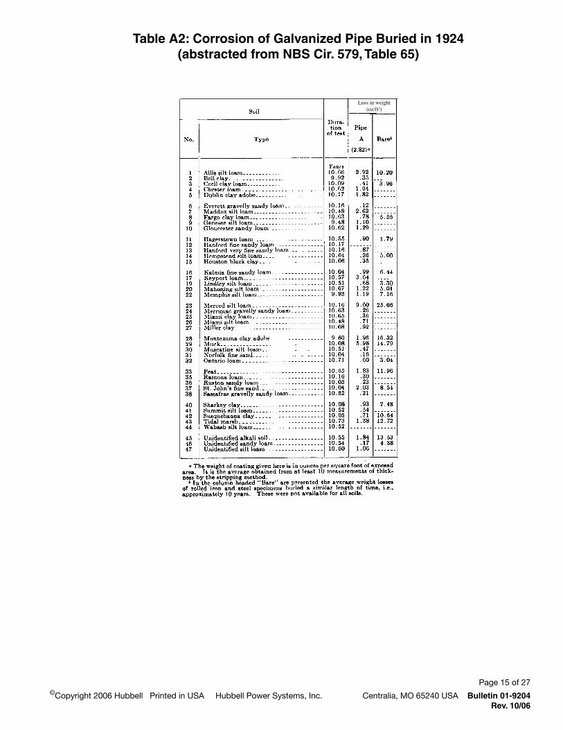
Table A2: Corrosion of Galvanized Pipe Buried in 1924(abstracted from NBS Cir. 579, Table 65)
Loss in weight(oz/ft2)
Page 6 of 27
Bulletin 01-9204 ©Copyright 2006 Hubbell Printed in USA Hubbell Power Systems, Inc. Centralia, MO 65240 USARev. 10/06
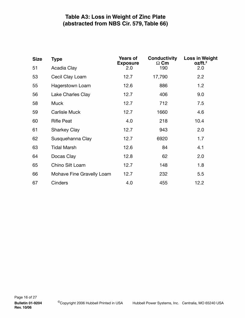
Table A3: Loss in Weight of Zinc Plate(abstracted from NBS Cir. 579, Table 66)
Size
5
5
55
56
5
5
60
6
62
6
64
65
66
67
Type
Acadia Clay
Cecil Clay Loam
Hagerstown Loam
Lake Charles Clay
Muck
Carlisle Muck
Rifle Peat
Sharkey Clay
Susquehanna Clay
Tidal Marsh
Docas Clay
Chino Silt Loam
Mohave Fine Gravelly Loam
Cinders
2.0
2.7
2.6
2.7
2.7
2.7
4.0
2.7
2.7
2.6
2.
2.7
2.7
4.0
Years of Exposure
ConductivityW Cm
0
7,70
6
406
72
660
2
4
620
4
62
4
22
455
Loss in Weightoz/ft.2
2.0
2.2
.2
.0
7.5
4.6
0.4
2.0
.7
4.
2.0
.
5.5
2.2

Page 7 of 27©Copyright 2006 Hubbell Printed in USA Hubbell Power Systems, Inc. Centralia, MO 65240 USA Bulletin 01-9204
Rev. 10/06
Sample Calculation on Expected Helix LifeAssume ⁄" allowable thickness loss for helix. Determine life of helical pier in soil having resistivity of 400, 000 & 000 Ω-cm.
Allowable Steel Loss:
=0.25 in 0.26 lb/in 6 oz/lb 44 in2 in.
** ft2
.66 oz/ft2
Loss inWt. oz/ft2
6. .5 4.
Loss perYr. oz/ft2
.70.00.25
YearsExposed
.66.
ResistivityOhm-cm
4000020
Site†No.24426
Total zinc coat loss:
ASTM A5 Coating B = . oz/ft2
6.62.
Not Available
0.50.
Not Available
..2
Not Available
406 4~000
566--
Years required for ⁄" steel loss and all zinc (YT)
Loss/yr. Steel.66 oz/ft2 +YT = Loss/yr. Zinc
. oz/ft2
YT
46 2.55.5
Years for Zinc
.5Use .5
Years for Steel 427226
Resistivity 4000020
See attached plot.
†Site Nos. Refer to data from Table A & A2.
Example Resistivity vs. Helix Life
400 —
00 —
200 —
00 —
0 —
60 —
40 —20 —0 —
400 — 000 2000 000 4000
Soil Resistivity W - cm
*

Page of 27
Bulletin 01-9204 ©Copyright 2006 Hubbell Printed in USA Hubbell Power Systems, Inc. Centralia, MO 65240 USARev. 10/06
Appendix B
Sample Calculation Anode Section
Table B1 Typical Resistivities
Table B2: Typical Anode Data
Table B3: Descriptions of Soil

Page of 27©Copyright 2006 Hubbell Printed in USA Hubbell Power Systems, Inc. Centralia, MO 65240 USA Bulletin 01-9204
Rev. 10/06
Example DesignAnode Selection
SS150ANCHOREXAMPLE
SURFACE AREA DATAROD: 11⁄2 x 11⁄2 x 7' = 3.5 Sq. Ft.Helix Area: 8 dia. = 1.1 Sq. Ft. 10 dia. = 1.5 Sq. Ft. 12 dia. = 1.8 Sq. Ft.
SAMPLECALCS:
On one wall: Assume 5 each 8 x 11⁄2 Sq. Ft.SS150 Anchors in 2500 ohm cm Soil
A = 5 x (1.1 + 3.5) = 23 ft2 Total
Ireq'd = 1.0 ma (*)/ft2 x 23 sq. ft. = 23 ma
FROM ANODE CHART TABLE
Using 2500 ohm cm Soil17# Anode = 26 yr. 9# Anode = 13 yr.
OR:
USEFUL LIFE OF ANODE @ 60% Consump.
.6 x 17 = 10.2 lb.
PROTECTS FOR:
Est. Life = 10.2#17.5#/Amp-Yr. .023 Amp
1 = 25.3 Yr.
(*) 1.0 ma/Sq. Ft. is usual current req’t assumed for buried steel. With low resist. (2000 ohm cm)

Page 20 of 27
Bulletin 01-9204 ©Copyright 2006 Hubbell Printed in USA Hubbell Power Systems, Inc. Centralia, MO 65240 USARev. 10/06
Table B-1 Typical Field Resistivities
MATERIAL
GraphiteSalt WaterLaomSilt-Loam (25% moisture)Gravel-sand-loam (wet)PeatClay-Silt (25% moisture)Adobe clay (25% moisture)Tidal clay-loamCoal coke breeze (moist)Sand & Clay (25% moisture)Shale (wet)Shale (dry)Sandstone (wet)Sandstone (dry)Limestone (25% moisture)Limestone (dry)CoalGlacial TillDry ClayConglomerateSlate (wet)Slate (dry)GranitePetroleum
OHM-CENTIMETERS
0.0320.
1500. 2500.
10000. 800. 600. 400. 250. 50.
1000. 2000.
1000000. 7000.
5000000. 15000.
100000. 10000. 50000. 60000.
200000. 64000.
650000. over 75 million
over 100 million

Page 2 of 27©Copyright 2006 Hubbell Printed in USA Hubbell Power Systems, Inc. Centralia, MO 65240 USA Bulletin 01-9204
Rev. 10/06
Table B-2 Typical Anode Data
MagnesiumAnodeDesignData-9#&17#Package(H-1Alloy-ASTMAlloyAZ-63)
ANODERES.(OHMS)
7.511 15 19 23 30 38 45 54 60 80
165
SOILRESISTIVITY(OHM-CM)
1000150020002500300040005000600070008000
10,00020,000
OUTPUT(MA)5740302421171412111084
LIFE(YEARS)17#(2)
1116212630374552576375
150
DRIVINGPOT.(MV)1
425438450463475500525550575600625650
9#(2)6911131620242730343980
17#(2)1116212630374552576375
150
NOTES:
1. Against cathode polarized to -0.900 volts vs. Cu-CuSO4 and adjusted for decrease in anode potential resulting from current output.
2. Estimated for useful effective life at 60% of anode weight. Typical consumption rate (17.5#/amp-year).
3. All figures are approximate estimates.

Page 22 of 27
Bulletin 01-9204 ©Copyright 2006 Hubbell Printed in USA Hubbell Power Systems, Inc. Centralia, MO 65240 USARev. 10/06
Table B3: Descriptions of Soils at the Test Sites(from NBS Circular 579,1957)

Page 2 of 27©Copyright 2006 Hubbell Printed in USA Hubbell Power Systems, Inc. Centralia, MO 65240 USA Bulletin 01-9204
Rev. 10/06
Table B3National Bureau of Standards test sites — Continued

Page 24 of 27
Bulletin 01-9204 ©Copyright 2006 Hubbell Printed in USA Hubbell Power Systems, Inc. Centralia, MO 65240 USARev. 10/06
Table B3National Bureau of Standards test sites — Continued

Page 25 of 27©Copyright 2006 Hubbell Printed in USA Hubbell Power Systems, Inc. Centralia, MO 65240 USA Bulletin 01-9204
Rev. 10/06
Table B3National Bureau of Standards test sites — Continued

Page 26 of 27
Bulletin 01-9204 ©Copyright 2006 Hubbell Printed in USA Hubbell Power Systems, Inc. Centralia, MO 65240 USARev. 10/06
Table B3National Bureau of Standards test sites — Continued

Page 27 of 27©Copyright 2006 Hubbell Printed in USA Hubbell Power Systems, Inc. Centralia, MO 65240 USA Bulletin 01-9204
Rev. 10/06
Table B3National Bureau of Standards test sites — Continued

Bulletin 01-9204Rev. 10/06 RGS 1M
20 N. Allen, Centralia, MO 65240 USAEmail: [email protected]: 573/682-8414 Fax: 573/682-8660
www.abchance.com www.atlassys.com
©Copyright 2006 Hubbell, Inc. Printed in USA
Because Hubbell has a policy of continu-ous product improvement, we reserve the right to change design and specifications without notice.
®
POWER SYSTEMS, INC.