analyzing and enhancing the security of ultrasonic sensors
TRANSCRIPT
IEEE INTERNET OF THINGS JOURNAL, VOL. 5, NO. 6, DECEMBER 2018 5015
Analyzing and Enhancing the Security of UltrasonicSensors for Autonomous Vehicles
Wenyuan Xu, Senior Member, IEEE, Chen Yan , Weibin Jia,Xiaoyu Ji, Graduate Student Member, IEEE, and Jianhao Liu
Abstract—Autonomous vehicles rely on sensors to measureroad condition and make driving decisions, and their safetyrelies heavily on the reliability of these sensors. Out of all obsta-cle detection sensors, ultrasonic sensors have the largest marketshare and are expected to be increasingly installed on automo-biles. Such sensors discover obstacles by emitting ultrasounds andanalyzing their reflections. By exploiting the built-in vulnerabili-ties of sensors, we designed random spoofing, adaptive spoofing,and jamming attacks on ultrasonic sensors, and we managed totrick a vehicle to stop when it should keep moving, and let it failto stop when it should. We validate our attacks on stand-alonesensors and moving vehicles, including a Tesla Model S with the“Autopilot” system. The results show that the attacks cause blind-ness and malfunction of not only sensors but also autonomousvehicles, which can lead to collisions. To enhance the securityof ultrasonic sensors and autonomous vehicles, we propose twodefense strategies, single-sensor-based physical shift authentica-tion that verifies signals on the physical level, and multiple sensorconsistency check that employs multiple sensors to verify sig-nals on the system level. Our experiments on real sensors andMATLAB simulation reveal the validity of both schemes.
Index Terms—Autonomous vehicle, defense, security analysis,ultrasonic sensor.
I. INTRODUCTION
AUTOMOBILE is one of the most promising sectors forthe Internet of Things (IoT). By converting vast amount
of data into meaningful and actionable knowledge, the IoT canhelp solve many of modern society’s challenges on automotivesafety and transportation efficiency. Among them, autonomous(self-driving) vehicles are one notable achievement, and itholds the key to a widespread Internet of Vehicles. Self-driving technologies are built on modern sensors that enablevehicles to monitor the driving environment by themselves.Already, a preliminary stage of self-driving has been widelydeployed as the advanced driver assistance systems. Lookingforward, vehicles will inevitably rely on these sensors and
Manuscript received February 10, 2018; revised April 7, 2018 and July 5,2018; accepted August 21, 2018. Date of publication August 30, 2018; dateof current version January 16, 2019. This work was supported in part byQihoo 360 Technology Inc., in part by the NSFC under Grant 61472358 andGrant 61702451, in part by the NSF under Grant CNS-0845671, and in partby the Fundamental Research Funds for the Central Universities under Grant2017QNA4017. (Corresponding author: Xiaoyu Ji.)
W. Xu, C. Yan, W. Jia, and X. Ji are with the Department ofElectrical Engineering, Zhejiang University, Hangzhou 310027, China(e-mail: [email protected]; [email protected]; [email protected];[email protected]).
J. Liu is with Qihoo 360 Inc., Beijing 100010, China (e-mail:[email protected]).
Digital Object Identifier 10.1109/JIOT.2018.2867917
their measurements to become increasingly intelligent untilthey reach the full-fledged self-driving capability, i.e., requirezero human interaction to make driving decisions. However,the safety of self-driving vehicles is determined by the relia-bility of sensors. Recent unfortunate fatal accidents [1], [2] ofTesla Model S with the Autopilot system [3] (i.e., the mostadvanced autonomous systems in the market) are caused bysensor failures, i.e., sensors cannot reliably detect neighboringcars in normal yet special road conditions. Such conditions arebenign, and it is worth investigating the malicious scenarios tounderstand the following: 1) how will these sensors performunder intentional attacks in practice?; 2) how will automobilesbehave under such attacks?; and 3) how to enhance these sen-sors to defend against intentional attacks? This paper answersthese questions with a case study on ultrasonic sensors.
Ultrasonic sensors detect obstacles and measure distanceby probing the surroundings actively with pulses of ultra-sound. They are widely used on IoT devices for ranging andoccupancy detection, which correspond to two scenarios on avehicle: 1) parking when a car is traveling at low speeds and2) detecting blind spot at high speeds. In terms of parkingsensors, more than half the new vehicles in Europe and Asiahave rear parking sensors [4], and the Indian government willsoon mandate all new vehicles to be equipped with such sen-sors to lower the risk of backover crashes [5]. Since NHTSAhas reported 292 fatalities with 44% of them being childrenunder five-year old and 18 000 injuries resulting from backovercrashes every year [6], it is not surprising that the global auto-motive parking sensors market is predicted to grow steadilyduring the next few years with a compound annual growthrate of almost 24% by 2020 [7]. As a pioneer of autonomousvehicle in the consumer market, Tesla Motors has alreadyemployed ultrasonic sensors for its “Autopark” and “Summon”feature (self-driving with driver outside the vehicle) [8] andto monitor the blind spot at high speed [9]. Thus, it is criticalto discover any vulnerabilities and implement remedies beforebillions of ultrasonic sensors are installed in vehicles and otherIoT devices for various purposes.
Determining the right rules to make moral and ethical deci-sion of self-driving cars is paramount, but it is far morecomplicated than one can imagine, because the driving deci-sions impact not only passengers’ safety but also the safetyof others. Thus, we focus on investigating the reliability ofultrasonic sensors and studying whether automobiles can makethe right driving decisions that depend on these sensors. Thegoal is to design strategies that can avoid potential automobile
2327-4662 c© 2018 IEEE. Personal use is permitted, but republication/redistribution requires IEEE permission.See http://www.ieee.org/publications_standards/publications/rights/index.html for more information.
Authorized licensed use limited to: Zhejiang University. Downloaded on May 06,2021 at 05:39:49 UTC from IEEE Xplore. Restrictions apply.

5016 IEEE INTERNET OF THINGS JOURNAL, VOL. 5, NO. 6, DECEMBER 2018
collisions. Thus, sensors should detect all present obstacles andavoid false alarms, and vehicles should handle the followingtwo scenarios correctly.
1) Stop With Obstacles: A vehicle should stop movingtoward obstacles on the driving path, and avoid activecollision.
2) Keep Moving Without Obstacles: A vehicle should keepmoving when there is no obstacle on the driving path,and prevent passive collision with the unprepared traffic.
We examine the feasibility of an attacker inducing incorrectdriving decisions by exploiting sensor design vulnerabilities,and report vulnerabilities found on current sensor systemsand real moving vehicles. To alleviate the threats, we designdefense strategies that protect ultrasonic sensors against theattacks and facilitate reliable automated driving decisions.
A. Contributions
We summarize the attacks that lead to incorrect drivingdecisions in Table I, and list our contributions from securityanalysis and security enhancement aspects below.
Security Analysis: To analyze the security of ultrasonicsensors in automobiles, we perform black-box experiments,reverse engineer the sensors’ printed circuit boards, and tapinto the signal path. We verify the attacks on 11 stand-aloneultrasonic sensors in the laboratory and the on-board sensorsof 7 vehicles (including a Tesla Model S) outdoors, using low-cost COTS hardware. To the best of our knowledge, we arethe first to experimentally examine the feasibility of attack-ing ultrasonic sensors on real moving vehicles. We are able toinduce the following incorrect driving decisions.
1) A Vehicle Stops When It Should Keep Moving: We trickthe on-board ultrasonic sensors to report nonexistingobstacles anywhere within the detection range by design-ing two types of spoofing attacks—random spoofingand adaptive spoofing. We can force a moving Tesla inSummon mode to stop by creating imaginary obstacles.
2) A Vehicle Keeps Moving When It Should Stop: We foundthat the design choices of ultrasonic sensors make it pos-sible to hide obstacles. A jamming attack or an adaptivespoofing attack can both prevent sensors from reportingobstacles. Our experiments show that an attacker cancause a moving Tesla in hand-driving mode to collideinto obstacles (e.g., students) from 10 m away and causecollision in the Summon mode from 1 m away.
Security Enhancement: Enhancing ultrasonic sensors ischallenging because any defense strategy that requires amajor modification of existing low-cost hardware will not beaccepted by the automotive industry. The narrow operationalfrequency band and long physical delays of ultrasound makeit difficult to utilize any traditional modulation-based schemes.We overcome all aforementioned challenges and design twosecurity mechanisms: 1) single-sensor-based physical shiftauthentication (PSA) and 2) multiple sensor consistency check(MSCC). Both can be used alone or in combination.
1) PSA: Despite the limitation of ultrasound, PSA allowsa sensor to send random probing signals. Thus, itcan detect obstacles reliably by checking whether thereceived echoes originate from the sensors.
TABLE IOVERVIEW OF ATTACK AND DEFENSE GOALS
2) MSCC: MSCC enables multiple sensors to collabora-tively address more advanced attacks at a system level. Itcan detect spoofing attacks, measure distance resiliently,and localize obstacles (both real ones and attackers).Utilizing two assistant sensors (ASs), MSCC can achievean improved detection rate.
We envision that the attack methodologies and enhancingtechnologies in this paper can provide insights for improvingthe security and reliability of autonomous vehicles, as wellas ultrasonic sensors in other IoT applications, such as smartcities, smart home, medical diagnostics, SCADA platforms,and robot technologies [10], [11].
II. BACKGROUND
In this section, we briefly introduce state-of-the-art auto-mated driving systems and the ultrasonic sensors.
A. Automated Driving System
An autonomous car (also known as, driverless car, self-driving car) is a vehicle that is capable of sensing its environ-ment and navigating without human input. According to theSAE J3061 report [12], there are six levels of driving automa-tion, from no automation (L0), to driver assistance (L1), partialautomation (L2), conditional automation (L3), high automa-tion (L4), and full automation (L5). Almost all cars that areat L2 and above are equipped with at least one type of activeobstacle detection sensors, i.e., ultrasonic sensors, for parkingassist. Tesla model S, as one of the most advanced autonomouscars in the market, is considered to be at L3 and has alreadyimplemented the “Autopilot” system [3], which consists offunctions like “Autopark” and “Autosteer” that monitor thesurroundings and act accordingly. Research teams such as theones at Google [13], Stanford [14], and Tesla Motors [15]are designing and experimenting fully autonomous prototypecars, but there is a long way to go before full application.Nevertheless, different levels of driving automation basicallyrely on the same types of sensor technologies, and the insightsgained from analyzing sensors on Tesla can shed light onfuture automobiles.
B. Ultrasonic Sensors
Ultrasonic sensors were first introduced to automobiles assensors of parking assistance systems in the early 1990s [16].Ultrasonic sensors detect obstacles by transmitting and receiv-ing ultrasound, which is one type of mechanical waveswhose frequency is beyond the upper limit of human hearing(20 kHz). To measure the distance to an object, an ultrasonic
Authorized licensed use limited to: Zhejiang University. Downloaded on May 06,2021 at 05:39:49 UTC from IEEE Xplore. Restrictions apply.
XU et al.: ANALYZING AND ENHANCING SECURITY OF ULTRASONIC SENSORS FOR AUTONOMOUS VEHICLES 5017
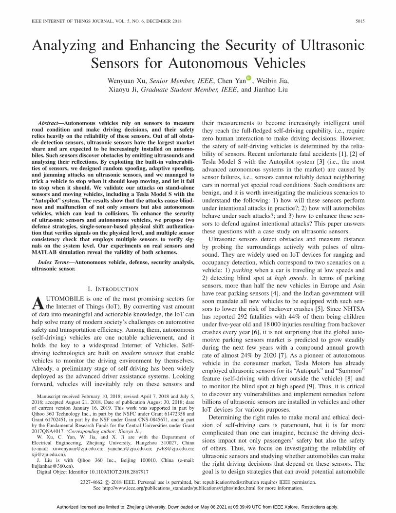
Fig. 1. Position and cross section of ultrasonic sensors.
sensor emits ultrasonic pulses (also known as pings), and mea-sures the time that it takes to receive the reflected pulses(also known as echoes). Distance to the nearest obstacle iscalculated based on the propagation time (time-of-flight, alsoknown as ToF) of the first received echo pulse according tothe equation
d = 0.5 · tp · vs (1)
where tp is the propagation time of ultrasonic pulses and vs isthe velocity of sound in air (343 m/s at 20 ◦C).
Fig. 1 shows an ultrasonic sensor consisting of a plastichousing, a piezoelectric transducer with an attached mem-brane, and a printed circuit board with the electronic circuitryand microcontroller to transmit, receive, and process thesignals. We introduce the main sensing principles and ourconcerns as follows.
Piezoelectric Effect: Most ultrasonic sensors on automobilesutilize piezoelectric crystals as transducers [17], which canconvert electric charges into mechanical vibrations and viceversa. For example, if a voltage is applied at the electrodes ofa piezoelectric crystal, a mechanical deformation results, andgenerates acoustic waves. On the contrary, an incoming acous-tic wave creates oscillations of the crystal, which generate analternating voltage at the electrodes. Note that it takes time forpiezo transducers to emit stable mechanical vibrations, and wecall this delay as start-up time.
Frequency: Ultrasonic sensors on vehicles typically oper-ate within a frequency band between 40 and 50 kHz, whichhas been proved as the best tradeoff between acousticalperformance (sensitivity and range) and robustness againstambient noises. Frequencies higher than 50 kHz will leadto weaker echoes due to the attenuation of airborne sounds,whereas for frequencies lower than 40 kHz the proportion ofinterfering sound is larger [18]. Unlike speakers, ultrasonicsensors tend to work at their resonance frequencies and cannotefficiently transmit wide-band signals.
Distance Measurement: When a sensor receives a commandfrom the electronic control unit (ECU) to transmit, its circuitexcites the transducer with periodic waves at the resonancefrequency for typically 300 μs, resulting in the membrane’svibration and emitting ultrasonic pings. Note that a transducercannot listen while transmitting. Even after it stops transmit-ting, the sensor cannot receive echoes immediately until aftera ring-down time (approx. 700 μs). Thus, ultrasonic sensorscannot detect objects in their close vicinity. Once rested, the
membrane can be vibrated again by the echoes, which are con-verted to analog signals, then amplified, filtered, digitized, andcompared to a threshold to determine the arrival of echoes.
III. ATTACK OVERVIEW
Before discussing the security vulnerabilities of ultrasonicsensors and their impact on automobiles, we specify ourassumptions on the threat model, introduce the basic ideasof our attacks, and summarize the attack categories.
A. Threat Model
In this paper, we focus on adversaries that attempt to attacka vehicle by falsifying the sensors’ output only via the physicalsignal channels. We assume their capabilities as follows.
Sensor Assessment: We assume that an adversary is awareof the underlying principles of the sensor systems, and hasbudgets and access to obtain such sensors for assessmentbeforehand. The adversary can acquire the parameters ofsensor designs, e.g., operational frequency, bandwidth, dutycycles, packet format, etc., and further explore sensor vul-nerabilities. The adversary may be proficient with hardwaredesign, and can exploit off-the-shelf hardware to accomplishthe assessment.
Attack Scenario: The adversary can eavesdrop on the phys-ical signals from on-board sensors, and actively generateforged echoes in an arbitrary form (frequency, amplitude, dura-tion, phase, etc.), thereby corrupting or overpowering otherconcurrent physical signals in propagation.
Contactless: An adversary can be anywhere around the tar-geted vehicle and is free to move. However, she does nothave control over the targeted vehicle or the on-board sensors.Moreover, the adversary must stay away from the targetedvehicle in order to remain stealthy during the attacks, andcannot make any physical alteration or damage to the sensors.
B. Physical Signal Level Attacks
In this paper, we study physical signal level attacks, whichtake advantage of the physical sensing channels to disrupt ormanipulate the sensor measurements.
Security Questions: Whether automobiles can make theright driving decisions in the two scenarios—with and with-out obstacles—depends on the reliability of sensors and thevehicles’ preprogrammed logic to react to various situations.Thus, we would like to answer the following questions in thepresence of physical signal level attacks.
1) Will a sensor report the detection of obstacles when thereis none?
2) Will a sensor report no obstacle when one or multiplereal obstacles exist?
3) Will an automobile handle the output of sensors prop-erly, especially abnormal sensory data?
4) If sensors malfunction under attacks, what defensemechanisms can be adopted to cope with them?
Attack Basics: Since ultrasonic sensors emit ultrasoundsto probe their surroundings, we utilize two types of well-known attacks as our building blocks to seek answers to theaforementioned questions: spoofing, whereby carefully crafted
Authorized licensed use limited to: Zhejiang University. Downloaded on May 06,2021 at 05:39:49 UTC from IEEE Xplore. Restrictions apply.
5018 IEEE INTERNET OF THINGS JOURNAL, VOL. 5, NO. 6, DECEMBER 2018
Fig. 2. Typical architecture of active sensor system on vehicles and the typeof attack of interest in this paper. The “echo” marked in red indicates beingcompromised by attack.
ultrasounds are injected so that they appear to come fromnonexisting sources and obfuscate real ones, and jamming,whereby noises are injected simply to interfere with sensors.
1) Spoofing Attacks: Spoofing attacks involve emittingcarefully crafted signals (e.g., ultrasound pulses) that areidentical to those transmitted by the sensors, i.e., withthe same frequency, modulation, etc. As a result, thesensors may interpret the spoofing signals the same wayas the authentic signals, and falsely detect nonexistingobstacles. By carefully adjusting the timing of the spoof-ing signals, an adversary may “create” fake obstacles atvarious locations of her choice.
2) Jamming Attacks: Jamming attacks involve injectingsimilar but stronger signals to overpower the real ones.Sensors are typically designed to be robust againstbenign ambient noises, but they hardly expect stronginterference. It is unclear whether sensors can detectobjects in the presence of jamming attacks. In casethe interference is so strong that it causes sensordenial-of-service, it is also unclear whether sensors andautomobiles will fail gracefully and do not cause fatalaccidents.
In the rest of this paper, we study both spoofing attacksand jamming attacks. Note that the longer the effective attackrange is, the more practical the attacks will be. The effectiverange of the attacks relies on both the operational range ofsensors and the transmission power of the attack equipment,which can be improved with budgets. The goal of this paper isto validate the feasibility of the attacks, and we do not focuson intentionally maximizing the transmission power, therebythe reported attack range serves as a reference. In practice,a motivated attacker can increase the transmission power andboost the effective attack range.
C. Attack Categorization
Ultrasonic sensors are one type of active sensors that emitphysical signals. To be general, we summarize attack clas-sification in terms of active sensors. Fig. 2 illustrates theinteraction of active sensors in an automobile. Inside an auto-mobile, an ECU controls several active sensors, which emitprobing pings to measure the environment and report distanceto obstacles, if there are any, back to the ECU. Then, the ECUwill transmit the measurement to other ECUs via the CAN busto fulfill functions such as self-parking. We envision that asmeasurements are generated and transmitted from sensors totheir ECU or other networked ECUs, three types of attacks
TABLE IIEXPERIMENTED STAND-ALONE SENSORS AND RESULTS
that target at various levels of sensor systems are possible,which include the following.
1) Physical Signal Level Attacks: Physical level attackstake advantage of the physical sensing channels to disrupt ormanipulate the analog sensor measurements. PS attacks onlymanipulate the surrounding physical environment or ambientsignals, e.g., the echoes in Fig. 2, and do not affect the dataprocessing path inside sensors.
2) Sensor Hardware Level Attacks: Hardware level attacksmanipulate sensor measurements by affecting how the sen-sory signals are collected and processed inside sensors. Forexample, Kune et al. [19] demonstrate injecting voice sig-nals into a Bluetooth headset and fake heart beats into animplantable pacemaker by blasting intentional EMI on the con-ducting wires inside sensors. Similarly, acoustic interferencehas been shown to be able to cause MEMS gyroscopes andaccelerometer to malfunction [20], [21].
3) Digital Level Attacks: Digital level attacks are, byfar, the most well-studied attacks, which include traditionalcyber attacks that alter digital information or invade systemsexploiting digital channels (e.g., network interfaces, filesystems, memories). For instance, researchers have demon-strated attacking automobiles via cellular networks [22] andCAN bus [23].
Although active sensors can be vulnerable to all three typesof attacks, we focus on physical signal level attacks becausethey are unique to active sensors and least studied.
IV. ATTACKING ULTRASONIC SENSORS
Analyzing the vulnerabilities of existing ultrasonic sen-sors begins with obtaining a thorough comprehension oftheir underlying principles. In particular, we investigate thefrequency, period, and modulation schemes of the ultrasonicprobing signals. Then, we design three types of attacks—random spoofing, adaptive spoofing, and jamming attacks—tounderstand whether sensors can detect obstacles reliably andwhether automobiles will cope with abnormal situations prop-erly. We validated all attacks on 11 models of stand-aloneultrasonic sensors (in Table II) in the laboratory. We also testedseven models of vehicles (in Table III) outdoors.
Authorized licensed use limited to: Zhejiang University. Downloaded on May 06,2021 at 05:39:49 UTC from IEEE Xplore. Restrictions apply.

XU et al.: ANALYZING AND ENHANCING SECURITY OF ULTRASONIC SENSORS FOR AUTONOMOUS VEHICLES 5019
TABLE IIIEXPERIMENTED VEHICLES AND RESULTS
A. Analyzing Sensors
To analyze the probing signals, we acquired 11 models ofstand-alone sensors, and one of them is an OEM parking assis-tance system consisting of one ECU and four sensors, whichis the same as the one on one of our tested vehicles. All ofthem report the distance to the closest obstacle if there is anywithin the detection range.
Methodology: From the public domain, we only learn thatultrasonic sensors operate in the range of 40 kHz to 50 kHz.To obtain details of the probing signals, we carried out twotypes of analysis.
1) Tapping into the signal pathway. The basic idea is asfollows. Applying alternating voltages on piezoelectriccrystals generates acoustic waves (i.e., mechanical oscil-lation), and the frequency and amplitude of the ac inputsignals determine the ones of the acoustic waves. Thus,analyzing the ac signals will reveal insights of the prob-ing signals, and we manage to use oscilloscopes tointercept the periodic waves that drive the piezoelectriccrystals.
2) Sampling over the air. Recording the emitted ultrasounddirectly will enable time and frequency domain analysis.However, generic microphones and ultrasonic sensorscannot record ultrasound that might spread tens of kHz.In the end, we used an off-the-shelf free field mea-surement microphone [24] (covering 4 Hz–90 kHz) tosample the ultrasound, and it outputs electrical signalsthat can be fed into an oscilloscope, spectrum analyzer,or smartphone application for further analysis.
Probing Signals: Both methodologies reveal the same find-ings on sensors: the probing pings are of the form of squarewaves with a constant amplitude, frequency, and duration. Dueto the short duration of each ping (e.g., 300 μs) and physi-cal delays, ultrasonic sensors do not employ any modulationschemes.
Probing Periods: We discover that sensors emit probingsignals periodically with two sensor algorithms (SA) illus-trated in Fig. 3: (a) SA1, periodic according to the first echoand (b) SA2, periodic according to probing signals. Most ofthe tested stand-alone sensors work as SA1 and wait a fixedamount of time, T1, either after the first echo or a timeoutto transmit the next probes. All sensors on the tested auto-mobiles are SA2 and transmit one ping every T2, regardlessof whether an echo occurs. This is because a vehicle ECUtriggers multiple sensors in a predefined order.
Fig. 3. Two probing algorithms: SA1 emits a probe after T1 from the firstecho. SA2 emits a probe periodically by T2.
B. Random Spoofing Attacks
Random spoofing attacks randomly replay the previouslyrecorded sensor signals hopefully at the right timing to deceivesensors, and do not try to cancel the sensor signals received atthis moment. Such attacks can at most delude the sensors toreport a forged obstacle that is closer than any real obstacles.We formalize the signals received by a sensor under randomspoofing attacks as
ϒi = �i(τ0) +N∑
n=1
�∗j (τn) (2)
where �i(τ ) is the echo of the ith cycle received after time τ0,�∗
j (τn) is a spoof signal replayed based on a previous cycle j(j < i) and received after time τn, and N is the total numberof spoof signals. An illustration of ϒi is shown in Fig. 4.
Random Spoofing Timing: Since the nearest obstacle is themost important one to automobiles, only the first received echosignal is reported by sensors. If there is no obstacle nearby,the sensors will wait for a predefined timeout duration T0,before starting the next cycle. T0 is determined by the sensingrange. Sensors only expect to receive echoes that are reflectedfrom any obstacles within a sensing range. For a 2-m range,T0 is nearly 11.7 ms. Thus, for an effective attack, the spoofsignals have to be received before the real echoes and withinthe timeout slot, whichever is sooner, i.e., min({τn}n∈[1,N]) <
min(τ0, T0) must be satisfied.Building a Random Spoofer: To validate spoofing attacks,
we acquired ultrasonic transducers whose working frequenciesare the same as the ones of the target sensors. To drive thetransducers, we utilize two types of off-the-shelf hardware:1) an Arduino [25] or 2) a function waveform generator.Arduinos can output square waves of selected frequencies onthe digital I/O pins using a built-in function named Tone(),which is mainly used to generate tones for speakers. Due toits low-cost nature, Arduino cannot generate a perfect periodicsignal without any frequency jitters. Nevertheless, the gener-ated square waves are sufficient for driving ultrasounds. Incomparison, a function generator outputs signals with morestable frequencies and higher amplitudes.
Results: Random spoofing attacks can decrease the values ofsensor measurement. We validated the random spoofing attackson stand-alone and on-board sensors. For both cases, we cancreate a forged obstacle that is closer than real obstacles, withslightly different observations.
1) Stand-Alone Sensors: For most stand-alone sensors thatadopt SA1, by selecting a spoofing period that is larger than
Authorized licensed use limited to: Zhejiang University. Downloaded on May 06,2021 at 05:39:49 UTC from IEEE Xplore. Restrictions apply.

5020 IEEE INTERNET OF THINGS JOURNAL, VOL. 5, NO. 6, DECEMBER 2018
Fig. 4. Illustration of all ultrasonic attacks. The waveforms show signalsa sensor receives in one sensing cycle, under no attacks, random spoofing,adaptive spoofing, and jamming attacks, respectively.
T1 and smaller than T1+T0, we were able to “create” a nonex-isting obstacle that appears to be stationary on the sensormeasurement. This is because the stand-alone sensor transmitsthe next probe after waiting for T1 since the first received echo.If we emit a spoof signal at the period of T1 + 2d/vs, wherevs is the speed of sound, the sensors will output a constantmeasurement of distance d.
2) On-Board Sensors: As shown in Fig. 7, by emittingspoof signals once every few milliseconds, we managed tomake the automobiles report obstacles that did not exist, whichkept causing alarms on all tested vehicles in Table III, andforced a moving Tesla Model S to stop in self-driving mode.The attacking distance was up to 2 m when powered withan Arduino, and can be increased with higher transmissionpower. Since a vehicle ECU triggers each sensor periodicallyas SA2, random spoofing is unable to synchronize strictly withthe pings, thus the imaginary obstacle appears to be movingon the sensor measurement. We observed the unsteadiness invarious ways: an obstacle jumped back and forth between twolocations; an obstacle appeared suddenly at random locations,as shown in Fig. 9(b). Nevertheless, none of the tested vehi-cles consider such abnormal results suspicious or warn driversaccordingly.
C. Adaptive Spoofing Attacks
A random spoofing attack cannot always precisely controlthe location of the spoofed obstacle and can at most createobstacles closer than the real ones. Thus, it can at most causean automobile to stop unnecessarily. The goal of an adaptivespoofing attack, however, is to create a nonexisting obstacle atan arbitrary yet stationary distance reliably, either closer (sub-tractive) or farther away (incremental) than the real one. Thus,it may cause an automobile to collide into a real obstacle, asillustrated in Fig. 5. To simplify the discussion, we assumethat the adaptive spoofer is a real obstacle itself.
Adaptive Spoofing Timing: To forge a stationary obstacle atany distance d for even SA2 sensors, the adaptive spoofer hasto transmit a spoof signal at the right timing, i.e., the sensorhas to receive the spoof signal after a delay of 2d/vs since
Fig. 5. Two types of spoofing attacks. The black circles are genuine obstaclesand red dashed ones are fake obstacles that can be created by attackers.
the transmission of probing pings, where vs is the speed ofthe sound. Thus, an adaptive spoofer has to listen and adjustto the concurrent sensor signals adaptively, and eliminate theexisting echoes for incremental distance. As such, adaptivespoofing attacks will involve three phases: 1) receiving sen-sor signals; 2) eliminating the echoes; and 3) transmitting thespoof signals. Similarly, the signals received under adaptivespoofing are
ϒi = �i(τ0) − α�i(τ0 + δ) + �∗i (τ1) (3)
where α is the index of signal cancellation and δ is the timedelay introduced by real-time processing.
Since on-board sensors are typically triggered periodically,an adaptive spoofer can calculate and predict τ1 by first mea-suring its distance to the sensor. Eliminating the echoes is notrequired when the imaginary obstacle is closer than the realobstacle, i.e., τ1 < τ0. However, in order for τ1 > τ0, echoelimination is necessary with proper α and δ. Acoustic qui-eting [26], [27] is a technique to cancel acoustic signals, andis well developed for stealth military submarines [28] as wellas commercial noise cancelling headphones [29]. All thesetechniques can be utilized to eliminate echoes. In our imple-mentation, we adopt a simple yet convenient method: we wrapthe adaptive spoofer with sound absorbing materials (e.g.,damping foams) and only expose the ultrasonic transducer inthe air. The damping foams can passively absorb sound suchthat the reflected echoes are too weak to be detected by thesensors.
Building an Adaptive Spoofer: An adaptive spoofer has tobe both a transmitter and receiver. We built an adaptive spooferout of two ultrasonic transducers, amplification circuits, abuffer amplifier, an envelope detector, and an Arduino board.The adaptive spoofer listens to sensor signals, and controlsthe timing for emission. Meanwhile, we attached the adaptivespoofer onto a traffic cone and wrap it with damping foams,as shown in Fig. 6.
Results: Adaptive spoofing attacks can decrease or increasethe measured distances. We were able to create a stationaryimaginary obstacle for both stand-alone and on-board sensors,and even manipulate its movement. The spoofer can be placedanywhere within the sensor’s working range (normally a fewmeters). For demonstration, we place the adaptive spoofer
Authorized licensed use limited to: Zhejiang University. Downloaded on May 06,2021 at 05:39:49 UTC from IEEE Xplore. Restrictions apply.
XU et al.: ANALYZING AND ENHANCING SECURITY OF ULTRASONIC SENSORS FOR AUTONOMOUS VEHICLES 5021
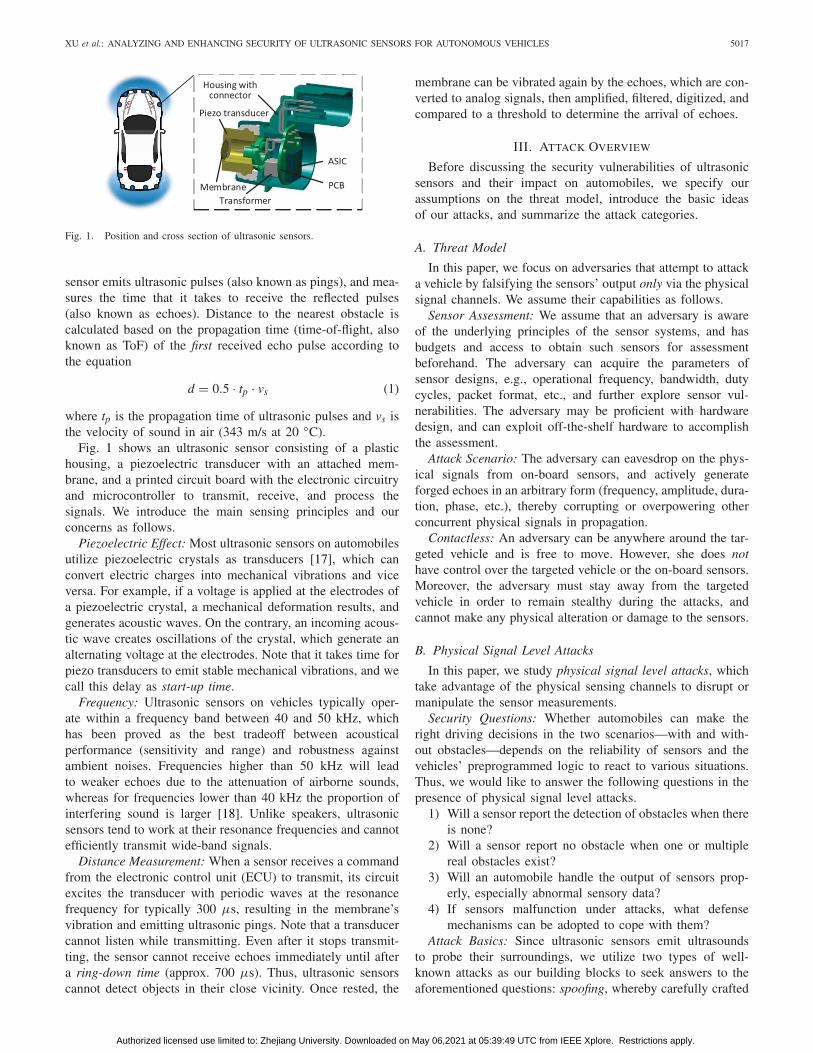
Fig. 6. Disguised Arduino-based adaptive spoofer and incremental spoof-ing results on sensor SRF01. The adaptive spoofer mimics a moving-awayobstacle by increasing the delay to transmit after receiving the sensor probe.
20 cm away from the sensor, and create an imaginary obstaclethat is gradually moving away from the sensor. In particu-lar, the spoofer will transmit a spoof signal with a delay of2nTvo/vs (n = 0, 1, 2, . . .), where vo is the speed of the imag-inary obstacle, n is the echo sequence, and T is the sensingperiod. Fig. 6 shows the distance measured by a victim sensorunder adaptive spoofing attacks—it illustrates the effectivenessof our attacks.
D. Jamming Attacks
Jamming attacks generate ultrasonic noises that induce con-tinuous vibration on the sensor membrane, and render distancemeasurement impossible. The goal is to cause a sensor fail todetect real obstacles, which may cause collisions.
Jamming Parameters: A jamming attack continuously emitsultrasounds toward a sensor such that the jamming signalsoverwhelm the echoes, as shown in Fig. 4. The signals receivedunder jamming attack are
ϒi = �i(τ0) +∫ T0
0A cos(ωt) (4)
where A is the jamming amplitude and ω is the frequency.Resonant Frequency: From our measurement on several
vehicles, we found that the operation frequency appears to benear 50 kHz. In practice we used off-the-shelf 40 kHz trans-ducers for jamming because 50 kHz ones were unavailable.Since ultrasonic transducers operate around a narrow band,the 40 kHz transducer cannot emit 50 kHz ultrasounds effi-ciently. Nevertheless, 40 kHz turned out to be effective, andwe believe the effective range could be expended with 50 kHztransducers.
Voltage Level: The amplitudes of sounds created by piezo-electric crystals rely on the voltage level of the signals thatdrive the crystals. Thus, the effective jamming distance isdetermined by the applied voltages. In our experiments, we usetwo types of equipment. Arduino can generate square waveswith 5 volts maximum, and the function generator outputs upto 20 volts. The ultrasonic transducers that we obtained cantake up to 70 volts, and we believe the effective attack rangecan go beyond what we observed.
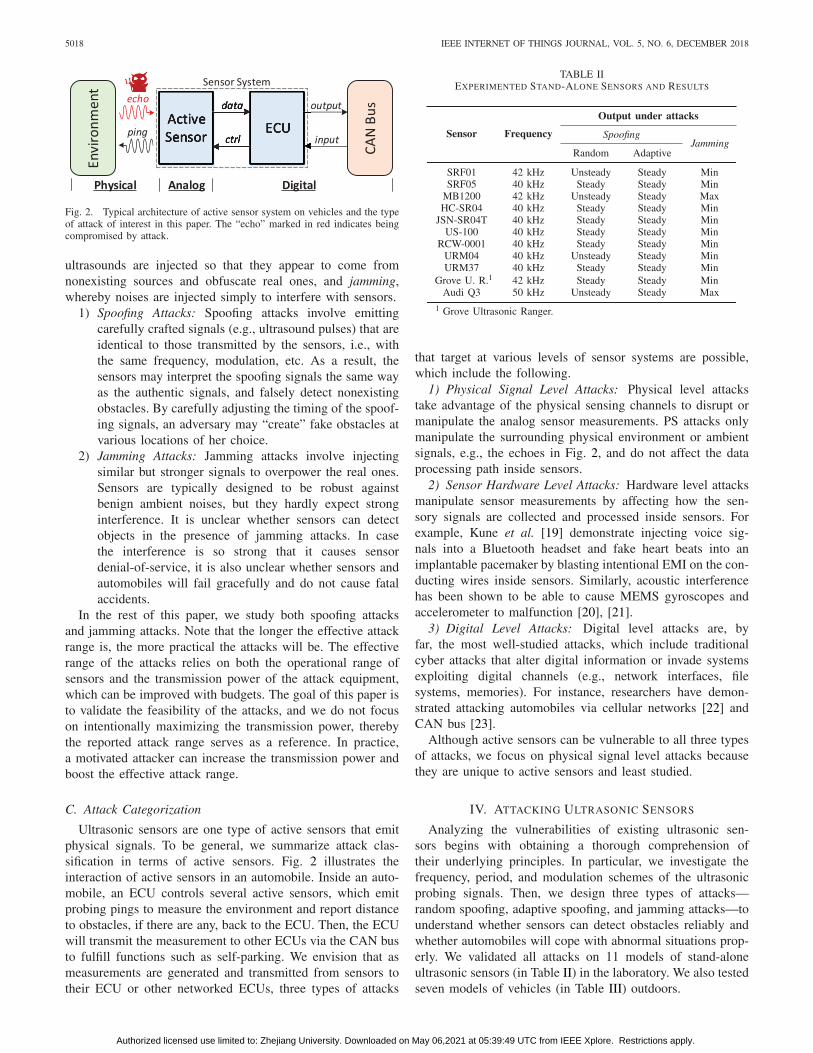
Fig. 7. Ultrasonic experiment setup on a Tesla Model S. A is the jammer,B is 3 sensors on the left-front bumper.
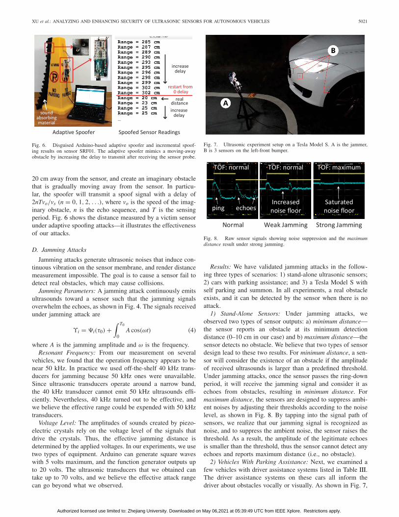
Fig. 8. Raw sensor signals showing noise suppression and the maximumdistance result under strong jamming.
Results: We have validated jamming attacks in the follow-ing three types of scenarios: 1) stand-alone ultrasonic sensors;2) cars with parking assistance; and 3) a Tesla Model S withself parking and summon. In all experiments, a real obstacleexists, and it can be detected by the sensor when there is noattack.
1) Stand-Alone Sensors: Under jamming attacks, weobserved two types of sensor outputs: a) minimum distance—the sensor reports an obstacle at its minimum detectiondistance (0–10 cm in our case) and b) maximum distance—thesensor detects no obstacle. We believe that two types of sensordesign lead to these two results. For minimum distance, a sen-sor will consider the existence of an obstacle if the amplitudeof received ultrasounds is larger than a predefined threshold.Under jamming attacks, once the sensor passes the ring-downperiod, it will receive the jamming signal and consider it asechoes from obstacles, resulting in minimum distance. Formaximum distance, the sensors are designed to suppress ambi-ent noises by adjusting their thresholds according to the noiselevel, as shown in Fig. 8. By tapping into the signal path ofsensors, we realize that our jamming signal is recognized asnoise, and to suppress the ambient noise, the sensor raises thethreshold. As a result, the amplitude of the legitimate echoesis smaller than the threshold, thus the sensor cannot detect anyechoes and reports maximum distance (i.e., no obstacle).
2) Vehicles With Parking Assistance: Next, we examined afew vehicles with driver assistance systems listed in Table III.The driver assistance systems on these cars all inform thedriver about obstacles vocally or visually. As shown in Fig. 7,
Authorized licensed use limited to: Zhejiang University. Downloaded on May 06,2021 at 05:39:49 UTC from IEEE Xplore. Restrictions apply.

5022 IEEE INTERNET OF THINGS JOURNAL, VOL. 5, NO. 6, DECEMBER 2018
(a) (b) (c)
Fig. 9. Dashboard on Tesla Model S showing distance to a nearby obstacleunder (a) no attack (the distance is real), (b) spoofing attack (the distanceis falsified), and (c) jamming attack (the distance is maximum and notdisplayed).
an ultrasonic jammer is placed in front of the car bumpers andcan be detected. Once a jamming attack is launched, the vehi-cle can no longer detect the obstacle and no alarm is triggered[Fig. 9(c)]. We believe that this maps to the maximum distancecase and the design of these sensors aims at noise reduction.Using a function generator, we can effectively attack a movingTesla from up to 10 m away.
3) Tesla Model S With Self-Driving: We further testedjamming attacks on the Autopark and Summon features ofTesla Model S. We were wondering whether jamming attackscan prevent automatic parking systems from detecting theobstacles reliably. The results we observed turned out to beprominent and worrisome.1 When the Tesla is jammed in self-parking or summon mode, the car moving by itself will ignoreobstacles and collide with them. The attack range is 1 m whenthe jammer is driven by a function generator, and it could beincreased excessively with power amplifiers.
E. Summary
In summary, we validated the following attacks.1) Random spoofing attacks can create imaginary obstacles
that are closer to an ultrasonic sensor than real obstacles.Although the forged distance may change constantly andunrealistically, it can force a moving autonomous vehicleto stop when it should not.
2) Adaptive spoofing attacks can create imaginary obstaclesthat are either closer or farther away than the real ones atpredetermined distances. The attacks can force a movingvehicle to stop when it should not, or not to stop whenit should.
3) Jamming attacks can prevent ultrasonic sensors fromdetecting obstacles, and cause vehicle collisions.
V. ENHANCING ULTRASONIC SENSORS
We design defense enhancement strategies that can copewith spoofing and jamming attacks against ultrasonic sensors,and aim at achieving the following levels of functions.
1) Attack Detection: At minimum, the defense strategiesshould be able to detect and report the attacks, therebydrivers or the self-driving systems can react to theattacks properly.
1We demonstrate with a video online. [Online]. Available:https://youtu.be/r4vS7YhT3DI
TABLE IVOVERVIEW OF THE DEFENSE SCHEME FUNCTIONS
2) Resilient Obstacle Detection: Despite the spoofingattacks, the enhanced algorithm should be able to iden-tify the spoofed echoes from real ones, and report thereal distance.
3) Attacker Localization: The most challenging task is tolocalize the attackers. We believe the location informa-tion of an attacker can help a driver or the self-drivingsystem to cope with the attacks, and can be used inforensics.
As illustrated in Fig. 2, an existing ultrasound-based obsta-cle detection system consists of a set of ultrasonic sensors(from 3 to more than 12) and an ECU. Thus, our enhancementincludes two types of schemes.
1) PSA-based method that allows each individual sensor todetect attacks and to perform resilient obstacle detection.
2) MSCC-based method that enables a set of ultrasonicsensors to collaboratively achieve the aforementionedfunctions.
We summarize the functions of each scheme against differ-ent attacks in Table IV. The schemes individually may not beable to protect the sensor system against all types of attacks,but their combination, as part of our systematic strategies, canenhance the reliability of the overall system, which we willdiscuss later.
A. Physical Shift Authentication
PSA authenticates physical signals by shifting the wave-form parameters. Essentially, physical signal level attacks arepossible because ultrasonic sensors transmit pings of the samewaveform throughout their lifetime and search for only the firstecho via energy-based detection, i.e., detecting any ultrasonicsignals whose amplitude is higher than a threshold. Thus, thereis no bond between a ping and its echoes. To detect attacksand possibly reject spoofed echoes, it is important to bindthem. As such, we propose a challenge-response scheme bycustomizing the ping waveform, then correlating the receivedechoes with the pings. A simple procedure of PSA can besummarized as follows.
Step 1: Randomize the ping waveform X. Transmit.Step 2: Receive. Measure the echo waveform Y.Step 3: If C(X, Y) < α, reject the echo.
Where X = [x1, x2, . . . , xn]T ∈ Rn is a vector of n selected
waveform features, Y = f (X) = [y1, y2, . . . , yn]T ∈ Rn is a
vector of n received waveform features, and f ∈ Rn×n is a
Authorized licensed use limited to: Zhejiang University. Downloaded on May 06,2021 at 05:39:49 UTC from IEEE Xplore. Restrictions apply.
XU et al.: ANALYZING AND ENHANCING SECURITY OF ULTRASONIC SENSORS FOR AUTONOMOUS VEHICLES 5023
conversion function. C is a function that determines the corre-lation of the waveforms, and α is a threshold. Our hypothesisis that the waveform of real echoes should be correlative to theprior ping, however, a waveform YA from a passive attackerwho does not know X will likely fail the challenge. Therefore,our approach in designing PSA is twofold: 1) examining thefeasibility of physical signal authentication on ultrasound and2) detecting spoofed echoes and real ones.
A unique challenge we face, is that ultrasonic sensorsreceive real echo signals with unknown parameters, evenwhen the transmitted signals are well-known and tuned. Forexample, the probing signal is typically
s(t) = cos(ωct), t ∈ [0, T] (5)
where ωc is the carrier frequency, and T is the time duration.After reflection, the received signal becomes
r(t) = a cos((ωc + ωD)(t − τ) + θ) + n(t), t ∈ [τ, τ + T]
(6)
where a represents signal attenuation, ωD is the Dopplershift, θ is a phase shift, n(t) is the additive noise compo-nent, and τ is the time delay (proportional to the round-tripdistance to the obstacle), all of which are unknown anddependent on the environment. There are sonar applicationswhere the signal frequency, amplitude, phase, and the analogwaveform are measured or estimated for advanced target mea-surement and identification [30]. However, it remains unknownwhether these physical parameters can be used for signalauthentication, especially when they include uncertainty afterreflection.
To examine the feasibility of modulating these parameters,we choose amplitude, frequency, phase, and ping duration ascandidates for the waveform feature xk. Formally, we considera sequence of customized pings, and let the waveform of theith ultrasonic ping be
si(t) = Ai cos(2π fit + ϕi), t ∈⎡
⎣i∑
j=1
�j,
i∑
j=1
�j + Ti
⎤
⎦ (7)
where Ai is the amplitude, fi is the frequency, ϕi is the phase,and Ti is the duration of the ith ping. �i is the period, i.e., thetime period between the ith and (i − 1)th ping (let �1 = 0).On existing sensors, all these waveform features are alwaysconstants, and pings are transmitted periodically with a fixedperiod �. In our experiments, we change each feature xk
independently, and seek for correlation in the reflected echoes.Ultrasonic transducers inherently have physical delays as
start-up and ring-down period [31]. Even if the signalsthat drive the sensors have constant amplitude, frequency,and phase, during these special periods, the amplitude andfrequency of the emitted ultrasound are unstable. Given thatthe duration of each ping is short and typically lasts for 8 to 20cycles of sinusoid, it is impossible to modulate all these param-eters efficiently within each ping. Thus, we prefer to modulatethe waveform as per ping instead of within each ping, i.e., eachping will have a constant amplitude, frequency, duration, andat most one phase shift, but they may be different betweenconsecutive pings.
We define the process of transmitting the ith ping and receiv-ing the following echoes as the ith cycle. We envision that theauthentication of received waveform feature yk can be donein two ways depending on the type of transmitted waveformfeature xk, as follows.
1) Per single cycle, where yk(i) is received if and only ifxk(i) has been transmitted, i.e., yk(i) ⇔ xk(i).
2) Per consecutive cycles, where receiving a sequence ofyk implies that a sequence of xk has been transmitted,i.e., {yk(i), yk(i + 1), . . . , yk(i + m)} ⇒ {xk(i), xk(i +1), . . . , xk(i + m)}.
The first case corresponds to those xk that do not changedramatically during one cycle, possibly frequency and phase.The second case can be applied when xk is highly dependenton the environment and reflecting surface, possibly amplitude,and ping duration. Our experiments focus on examining thefeasibility of employing the proposed xk candidates for theabove cases, i.e., whether they can be used for PSA and howto use them.
Although ideas similar to PSA have been tested on RFsignals, its feasibility on ultrasonic sensors in automotiveapplications still remains unanswered. We ask the follow-ing questions: 1) Can we reliably modify the amplitudeAi, frequency fi, phase ϕi, duration Ti, and period �i ofeach ping? 2) Once the waveform of a ping is modi-fied, will the corresponding echo change proportionally tothe ping? 3) How reliably can we differentiate the mod-ulated echoes with the spoofed echoes from a passiveattacker?
To answer these questions, we use the following experi-ment setup. We set two ultrasonic transducers—one transmitterdriven by a signal generator and one receiver connected to anoscilloscope—side by side toward an obstacle close by. Thereflected signals can be observed and measured on the oscil-loscope after amplification. We analyze the feasibility of eachxk candidate in the next few sections.
1) Frequency Shift: We ask the following questions forfrequency shift: Can sensors create ultrasounds at vari-ous frequencies? Will reflection on an obstacle modify thefrequency randomly?
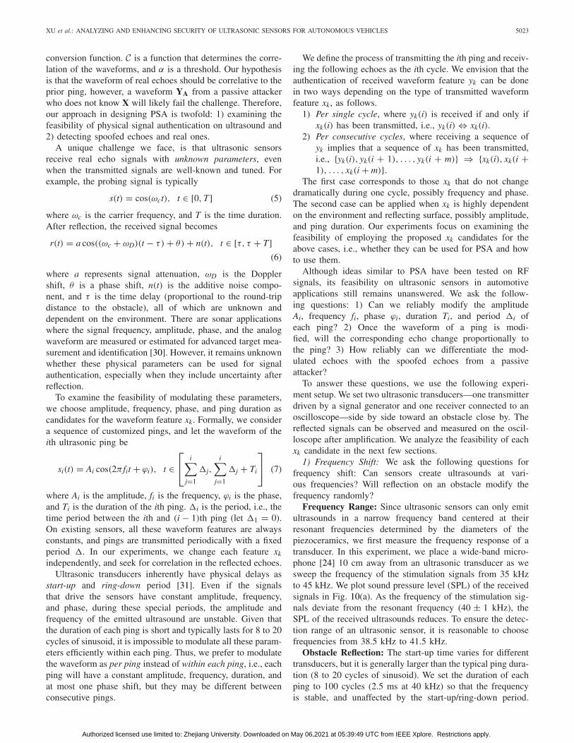
Frequency Range: Since ultrasonic sensors can only emitultrasounds in a narrow frequency band centered at theirresonant frequencies determined by the diameters of thepiezoceramics, we first measure the frequency response of atransducer. In this experiment, we place a wide-band micro-phone [24] 10 cm away from an ultrasonic transducer as wesweep the frequency of the stimulation signals from 35 kHzto 45 kHz. We plot sound pressure level (SPL) of the receivedsignals in Fig. 10(a). As the frequency of the stimulation sig-nals deviate from the resonant frequency (40 ± 1 kHz), theSPL of the received ultrasounds reduces. To ensure the detec-tion range of an ultrasonic sensor, it is reasonable to choosefrequencies from 38.5 kHz to 41.5 kHz.
Obstacle Reflection: The start-up time varies for differenttransducers, but it is generally larger than the typical ping dura-tion (8 to 20 cycles of sinusoid). We set the duration of eachping to 100 cycles (2.5 ms at 40 kHz) so that the frequencyis stable, and unaffected by the start-up/ring-down period.
Authorized licensed use limited to: Zhejiang University. Downloaded on May 06,2021 at 05:39:49 UTC from IEEE Xplore. Restrictions apply.
5024 IEEE INTERNET OF THINGS JOURNAL, VOL. 5, NO. 6, DECEMBER 2018
(a) (b) (c)
(d) (e) (f)
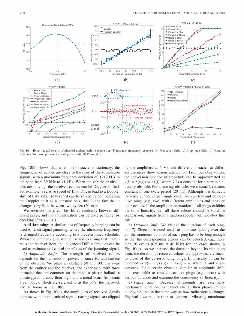
Fig. 10. Experimental results of physical authentication schemes. (a) Transducer frequency response. (b) Frequency shift. (c) Amplitude shift. (d) Durationshift. (e) Oscilloscope waveform of phase shift. (f) Phase shift.
Fig. 10(b) shows that when the obstacle is stationary, thefrequencies of echoes are close to the ones of the stimulationsignals, with a maximum frequency deviation of 0.212 kHz inthe band from 39 kHz to 41 kHz. When the vehicle or obsta-cles are moving, the received echoes can be Doppler shifted.For example, a relative speed of 15 km/h can lead to a Dopplershift of 0.48 kHz. However, it can be solved by compensatingthe Doppler shift as a constant bias, due to the fact that itchanges very little between two cycles (20 ms).
We envision that fi can be shifted randomly between dif-ferent pings, and the authentication can be done per ping, bychecking if y(i) = x(i).
Anti-Jamming: A similar idea of frequency hopping can beused to resist signal jamming, where the ultrasonic frequencyis changed frequently according to a predetermined schedule.When the jammer signal strength is not so strong that it satu-rates the receiver front end, advanced DSP techniques can beused to estimate and cancel the effects of the jamming signal.
2) Amplitude Shift: The strength of received echoesdepends on the transmission power, distance to, and surfaceof the obstacle. We place an obstacle 50 and 100 cm awayfrom the emitter and the receiver, and experiment with threeobstacles that are common on the road: a plastic bollard, aplastic pyramid cone floor sign, and a metal board (to mimica car body), which are referred to as the pole, the pyramid,and the board in Fig. 10(c).
As shown in Fig. 10(c), the amplitudes of received signalsincrease with the transmitted signals (strong signals are clipped
by the amplifiers at 5 V), and different obstacles at differ-ent distances show various attenuation. From our observation,the conversion function of amplitude can be approximated asy(i) = f (x(i)) = λx(i), where λ is a constant for a certain sta-tionary obstacle. For a moving obstacle, we assume λ remainsconstant in one cycle period (20 ms). Although it is difficultto verify echoes in per single cycle, we can transmit consec-utive pings (e.g., two) with different amplitudes and measuretheir echoes. If the amplitude attenuation of all pings exhibitsthe same linearity, then all these echoes should be valid. Incomparison, signals from a random spoofer will not obey thisrule.
3) Duration Shift: We change the duration of each ping,i.e., Ti. Since ultrasound tends to attenuate quickly over theair, the minimum duration of each ping has to be long enoughso that the corresponding echoes can be detected, e.g., morethan 20 cycles (0.5 ms at 40 kHz) for the cases shown inFig. 10(d). As we increase the duration beyond its minimumlimit, the duration of received echoes are approximately linearto those of the corresponding pings. Empirically, it can bemodeled as y(i) = f (x(i)) = λx(i) + υ, where λ and υ areconstants for a certain obstacle. Similar to amplitude shift,it is reasonable to emit consecutive pings (e.g., three) withvarious duration and examine the consistency of linearity.
4) Phase Shift: Because ultrasounds are essentiallymechanical vibration, we cannot change their phases imme-diately, i.e., not in the same way as how radio signals change.Physical laws require time to dampen a vibrating membrane
Authorized licensed use limited to: Zhejiang University. Downloaded on May 06,2021 at 05:39:49 UTC from IEEE Xplore. Restrictions apply.
XU et al.: ANALYZING AND ENHANCING SECURITY OF ULTRASONIC SENSORS FOR AUTONOMOUS VEHICLES 5025
TABLE VCOMPARISON OF DIFFERENT WAVEFORM PARAMETERS
and then drive it into the new phase. To understand this, con-sider a phase shift (e.g., 180◦) as a sudden shift of forcedirection on the vibrating membrane of a transducer. Whenthe force is shifted to a reverse direction, the membrane grad-ually decreases the amplitude and then increases following thenew phase. Fig. 10(e) illustrates this phenomenon.
To validate whether we can perform an arbitrary phase shift,we performed the following experiments. We drive the ultra-sonic transmitter with a vector signal generator [32] capable ofphase modulation, and measure the phase shift of the ampli-fied echoes on an oscilloscope. Suppose the phases before andafter phase shift are ϕA and ϕB. To obtain the phase shift|ϕA − ϕB|, we introduce a reference signal with phase ϕR onanother channel of the oscilloscope, measure two phase differ-ences ϕA −ϕR and ϕB −ϕR, and subtract the results. As shownin Fig. 10(f), the received phase shifts are close to the modu-lated phase shifts, i.e., y(i) ≈ x(i). Similar to frequency shift,phase shift authentication can be achieved per single cycle.
5) Period Shift and Speed Filter: Period shift is designed asa supplement to the above schemes. Its motivation is to identifyattacks by the instability of spoofing results. It requires the sen-sor to repeatedly probe for two or more consecutive cycles, andmeasure the difference in distance estimation between cycles.Intuitively, if a sensor and obstacle are relatively still, the dis-tance measurement in different cycles should be almost thesame. If either party moves, the relative speed can be calcu-lated from the displacement per period. By shifting the probingperiod, we can increase the time jitter caused by spoof sig-nals from random or subtractive adaptive spoofers, and filterout obstacles that appear to move at unrealistic speed. Forexample, consider a sensor that probes every 20 ms and cov-ers a range of 3 m. A spoofer that induces 1 ms jitter on theToF will cause a distance offset of roughly 17 cm. However,moving 17 cm in 20 ms indicates a relative speed of 8.5 m/s(30.6 km/h), which is unlikely and should be rejected.
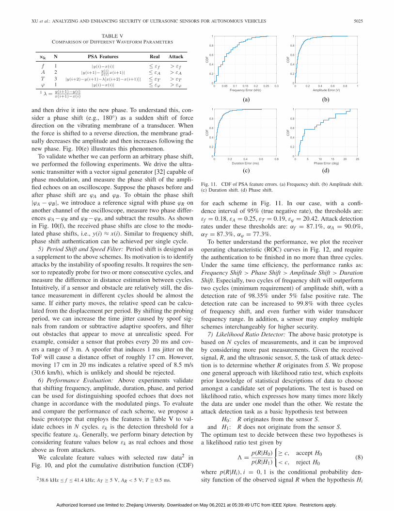
6) Performance Evaluation: Above experiments validatethat shifting frequency, amplitude, duration, phase, and periodcan be used for distinguishing spoofed echoes that does notchange in accordance with the modulated pings. To evaluateand compare the performance of each scheme, we propose abasic prototype that employs the features in Table V to val-idate echoes in N cycles. εk is the detection threshold for aspecific feature xk. Generally, we perform binary detection byconsidering feature values below εk as real echoes and thoseabove as from attackers.
We calculate feature values with selected raw data2 inFig. 10, and plot the cumulative distribution function (CDF)
238.6 kHz ≤ f ≤ 41.4 kHz; AT ≥ 5 V, AR < 5 V; T ≥ 0.5 ms.
(a) (b)
(c) (d)
Fig. 11. CDF of PSA feature errors. (a) Frequency shift. (b) Amplitude shift.(c) Duration shift. (d) Phase shift.
for each scheme in Fig. 11. In our case, with a confi-dence interval of 95% (true negative rate), the thresholds are:εf = 0.18, εA = 0.25, εT = 0.19, εϕ = 20.42. Attack detectionrates under these thresholds are: αf = 87.1%, αA = 90.0%,αT = 87.3%, αϕ = 77.3%.
To better understand the performance, we plot the receiveroperating characteristic (ROC) curves in Fig. 12, and requirethe authentication to be finished in no more than three cycles.Under the same time efficiency, the performance ranks as:Frequency Shift > Phase Shift > Amplitude Shift > DurationShift. Especially, two cycles of frequency shift will outperformtwo cycles (minimum requirement) of amplitude shift, with adetection rate of 98.35% under 5% false positive rate. Thedetection rate can be increased to 99.8% with three cyclesof frequency shift, and even further with wider transducerfrequency range. In addition, a sensor may employ multipleschemes interchangeably for higher security.
7) Likelihood Ratio Detector: The above basic prototype isbased on N cycles of measurements, and it can be improvedby considering more past measurements. Given the receivedsignal, R, and the ultrasonic sensor, S, the task of attack detec-tion is to determine whether R originates from S. We proposeone general approach with likelihood ratio test, which exploitsprior knowledge of statistical descriptions of data to chooseamongst a candidate set of populations. The test is based onlikelihood ratio, which expresses how many times more likelythe data are under one model than the other. We restate theattack detection task as a basic hypothesis test between
H0: R originates from the sensor S.and H1: R does not originate from the sensor S.
The optimum test to decide between these two hypotheses isa likelihood ratio test given by
� = p(R|H0)
p(R|H1)
{≥ c, accept H0
< c, reject H0(8)
where p(R|Hi), i = 0, 1 is the conditional probability den-sity function of the observed signal R when the hypothesis Hi
Authorized licensed use limited to: Zhejiang University. Downloaded on May 06,2021 at 05:39:49 UTC from IEEE Xplore. Restrictions apply.

5026 IEEE INTERNET OF THINGS JOURNAL, VOL. 5, NO. 6, DECEMBER 2018
Fig. 12. ROC curves for different PSA parameters in no more than threecycles.
is true. c is the decision threshold for accepting or rejectingH0. The task can be solved with a right probability model offeature value distribution, and we will not discuss here.
B. Multiple Sensor Consistency Check
We present an ECU algorithm that can achieve resilientobstacle detection and attacker localization based on a single-transmitter multiple-receiver sensor structure, where at a timeonly one sensor transmits and multiple sensors (three or more)receive, and check the consistency of measurement. Sincemodern vehicles are typically equipped with multiple sensors,they can support MSCC-based defense strategy. The basic ideaof the scheme is to utilize the redundancy information fromdifferent sensor positions to detect the inconsistency caused bythe spoofer. In particular, an ultrasonic transducer emits ultra-sound beams in the shape of a torchlight, which exhibits anemission angle (e.g., 60◦ for [33]). Thus, as a spoofer emits aforged echo, multiple sensors may receive it, and combine theirmeasurement to check consistency, thereby reject the spoofedechoes and accept the real ones.
In summary, depending on the number of sensors that canoverhear the echoes, the ability of this algorithm is as follows.
• Two Sensors: MSCC cannot detect attacks, but canlocalize obstacles no matter real or fake.
• Three or More Sensors: MSCC can detect attacks, esti-mate the distance to obstacles resiliently under randomand adaptive spoofing attacks, and localize the attacker.
1) Regular MSCC and Enhanced MSCC: Since the detec-tion rate of MSCC depends on the available number of sensors,we design two sensor layouts to support MSCC algorithms: aregular MSCC and an enhanced MSCC. A regular MSCC con-tains N sensors that are evenly distributed on the front and rearof an automobile, e.g., a 200 cm line. The enhanced MSCCadds two more ASs beside each of the N sensors. As shown inFig. 13(b), A3 and A4 are placed 5 cm away from the originalsensor S2. ASs do not transmit, instead, they receive echoesand detect attacks based on the MSCC method.
2) Localizing Obstacles: The underlying principle ofMSCC-based scheme is to localize obstacles with a pair ofsensors, as illustrated in Fig. 14(a). In one sensing cycle, onlyone sensor (e.g., SA) transmits, while both sensors receive andmeasure ToFs. SA’s output tA is the ToF from SA to and from
(a) (b)
Fig. 13. Simulation layout for two MSCC schemes. The detection area(shaded) is enlarged with enhanced MSCC. (a) Regular MSCC. (b) EnhancedMSCC.
(a) (b)
Fig. 14. Illustrations of MSCC scheme principles. (a) Localization.(b) Resilient detection.
the obstacle, while SB’s output tB is the ToF from SA to theobstacle and then to SB. Consider the case that the obstacleis farther to SB than SA by �D = (tB − tA) · vs, where vs isthe speed of sound. According to the measurement of SA, thepossible location of the obstacle is a circle of a radius tA ·vs/2centered at SA. According to the difference between tB and tA,the possible location is on a branch of hyperbola with foci SA,SB, and vertex distance 2a = �D. Thus, the true location ofthe obstacle is the intersection of the two curves.
3) Resilient Obstacle Detection: Let two sensors eachtransmits for one cycle, we can obtain two location estimationsof an obstacle. If the obstacle is real, the two estimation shouldbe almost the same. In the presence of a random spoofer or asubtractive adaptive spoofer who do not adjust to the timing ofprobing signals, the difference between two estimations willbe distinct. However, an incremental adaptive spoofing attackeradds a constant delay as soon as receiving the probing signals,and will create the same estimations in each cycle. Thus, twosensors are insufficient to detect incremental adaptive spoof-ing attacks. MSCC scheme aims to solve this problem byintroducing a third sensor SC in Fig. 14(b).
Consider an MSCC structure with three sensors. Since onesensor pair will provide one location, two pairs will providetwo. When sensor SA transmits, all three sensors receive andoutput ToFs: tA, tB, and tC. Likewise, given tA and tC, thepotential location of the obstacle is on the hyperbola withfoci SA, SC, and vertex distance 2a = (tC − tA) · vs. Now thecircle centered at SA with r = tA · vs/2 will intersect with twohyperbolas at two points, i.e., two locations.
Authorized licensed use limited to: Zhejiang University. Downloaded on May 06,2021 at 05:39:49 UTC from IEEE Xplore. Restrictions apply.

XU et al.: ANALYZING AND ENHANCING SECURITY OF ULTRASONIC SENSORS FOR AUTONOMOUS VEHICLES 5027
(a) (b)
Fig. 15. Simulation results showing that detection rate can be increasedwith enhanced MSCC, more sensors and larger transducer angle. (a) Sensornumber and structure. (b) Transducer angle.
We then check the obstacle locations. If echoes are reflectedfrom a real obstacle, the radius tA·vs/2 will be the real obstacledistance dAO. Thus, the two locations will coincide at obstacleO. However, if O is a spoofer emitting ultrasound actively,the two locations will be distinct as tA is spoofed (as the redcircles show). Given the ToFs from a basic triple-sensor MSCCstructure, any attempt to spoof the sensors translates into theinconsistency of localizations in one sensing cycle. By filteringout the inconsistent obstacles, we can achieve resilient obstacledetection.
4) Localizing Attacker: Notice that the spoof signals areemitted at the same time from the attacker but received bymultiple sensors at different time. The ToF is determined bythe geographical layout of sensors. Thus, for a stationary emit-ter (i.e., the spoofer), the two hyperbolas in Fig. 14(b) is fixed,and their intersection O is the location of the spoofer no mat-ter what the spoofed tA is. This method is also known asmultilateration in radio navigation systems.
5) Evaluation: To validate the effectiveness of MSCCmethod, we implemented the algorithm in MATLAB, and stud-ied both the regular MSCC and enhanced MSCC designs. Werandomly set an attacker in a 200 × 200 cm region aheadof the sensors, as shown in Fig. 13. We assume the attackeris aimed perpendicularly to the sensor plane, and has thesame transducer angle as the sensors for performance tradeoff.The dashed lines indicate the limits of sensor transmis-sion/receiving, and divide the region into areas by the numberof sensor overlap. Since the attacker can only be detectedand localized with three or more sensors, our scheme willdetect attackers above the blue margin. The enhanced MSCCdesign enlarges the detection area (shaded blue) by three times.Moreover, as shown in Fig. 15(a), the enhanced MSCC (thefour triples) dramatically improves the detection rate whenthe attacker is close, comparing with the same number (12)of evenly distributed sensors. In addition, Fig. 15(a) and (b)together shows that the detection rate can be raised by enlarg-ing the detection area, through either increasing the sensornumber or transducer angle.
C. Systematic Strategies
Though we propose PSA and MSCC as effective mitiga-tion methods to the attacks in this paper, systematic designstrategies are necessary for enhancing the reliability of theoverall sensing systems against future threats. We envision
that the security principle in designing ultrasonic sensorsystems should adopt the following two complimentary aspectssimultaneously.
• Individual sensors should provide reliable measurements.• Multiple sensors should collaborate to achieve reliability
which is otherwise impossible for individual sensors.1) Securing Individual Sensors: For individual sensors,
each of their measurements can be enhanced independentlyor collectively. PSA is an effective method to secure eachmeasurement independently, while Kalman filters can be usedto improve the reliability of a sequence of measurement. AKalman filter [34] fuses data measured in successive timeintervals to provide a maximum likelihood estimation of aparameter, e.g., distance, and it is widely used to track obsta-cles by filtering and prediction. Since most attacks introduceabrupt changes to the sensor measurements, a Kalman filtercould reduce the impact of transient attacks and detect attacksby setting a threshold on the error correlation matrix.
2) Multisensor Data Fusion: Three types of sensor fusionare applicable to ultrasonic systems: a) complementary;b) competitive; and c) cooperative. Complementary fusionrefers to the configuration that sensors do not directly dependon each other but can be combined to provide a more completeimage of observation. It is the current configuration on mostvehicles—multiple sensors are installed around a vehicle inorder to detect obstacles from different directions. Competitivefusion involves adding redundant sensors for the measurementof the same obstacle. Since it is difficult for an adversaryto jam or spoof multiple sensors at the same time, a votingscheme or confidence tags [35] can be used to indicate thetrustworthiness of an observation. Cooperative fusion derivesinformation that is unavailable from individual sensors. MFCCis such a scheme that can estimate 2-D locations and achieveresilient obstacle detection. Measurements from ultrasonic sen-sors can also be fused at a higher level with other types ofsensors, e.g., cameras and Lidars, if there are any.
VI. DISCUSSION
A. Overhead of Defense
PSA requires to authenticate echoes by waveform pro-cessing, which is a mature technology in ultrasonic levelmeasurement [31]. MSCC requires multiple sensors to performtrilateration, which is a software-based solution and can beemployed on vehicles to improve distance measurement [18].
B. Defense Awareness
Even if the attacker is aware of the defense mechanisms,she cannot predict the randomness of PSA, or hide her geo-graphical properties imposed by physical laws from MSCC.
C. Dealing With Other Attacks
Other attacks that might bypass our defense may be avail-able, e.g., wide-band jamming attack. However, we aim toraise the bar of attacks and let automobiles make the best driv-ing decision, e.g., a vehicle could stop when it detects jammingattacks. In addition, we encourage integrating informationfrom different types of sensors to improve the resilienceagainst more attacks.
Authorized licensed use limited to: Zhejiang University. Downloaded on May 06,2021 at 05:39:49 UTC from IEEE Xplore. Restrictions apply.

5028 IEEE INTERNET OF THINGS JOURNAL, VOL. 5, NO. 6, DECEMBER 2018
D. Dealing With Multiple Attackers
An attacker may want to disrupt the defense mechanismswith multiple coordinated transducers. However, PSA will beable to detect each attacker, and MSCC can detect subtractiveadaptive spoofing attacks in the presence of multiple col-luding attackers. Again, our intention is to raise the bar ofattacks, instead of building a bulletproof system, and we inviteresearchers to improve the reliability of sensors.
VII. RELATED WORK
Previous work on vehicle security mostly focused on thedigital communications inside and outside an automobile.The infrastructure of modern vehicles is designed in such away that all components are networked with each other bythe CAN-bus to exchange information. This structure facili-tates the functionality and efficiency of modern vehicles, butposes a serious threat in addition to potential insecure com-ponents [36], [37]. Several studies [38], [39] have shownthe feasibility of launching CAN-bus attacks, mainly throughOBD-II port, to cause malfunction and even take control ofthe car. In addition, it is possible to launch attacks [22], [23]remotely, if it contains external attack surfaces [40].
Several studies have examined the security of passive sen-sors, e.g., microphones and medical devices [19], MEMSgyroscopes [20], and MEMS accelerometers [21]. As for activesensors, Petit et al. [41] and Shin et al. [42] examined the secu-rity of LiDAR. The security of FMCW radars has been studiedin [43] without experiment on real cars. Shoukry et al. [44]proposed a physical challenge-response authentication schemefor magnetic encoders and RFID tags. We argue that theirmethods may not apply well to ultrasonic sensors due tothe physical latency of acoustic vibration and piezoelectrictransducers, i.e., acoustic waves cannot change fast enoughto satisfy the scheme requirements as RF signals. Despitethe valuable insights gained from previous studies, differenttypes of sensors adopt distinct underlying physical principles,therefore pose unique security challenges. We generalize ourmethods as physical signal level attacks, validate this approachon real vehicles with autonomous driving system, and proposeenhancement strategies. Some topics of this paper have beenpresented by the authors previously in a nonacademic talk [45].
The differentiation of ultrasonic probing signals has beenstudied mainly for solving intersensor interference, by meansof TDMA scheduling [46], [47] or multicode modula-tions [48], [49]. The structure of multiple ultrasonic sensorshas been used for identifying multiple objects [50]. Spatial–temporal phase dynamics has been utilized for RFID-basedrelative object localization [51]. These schemes are mainlydeveloped for applications (e.g., target tracking and RFID)rather than automobiles, and do not consider malicious attackson vehicular sensors.
VIII. CONCLUSION
The reliability of ultrasonic sensors remains a critical ques-tion, especially when it shapes the safety of autonomousvehicles. This paper validated the feasibility of three typesof attacks—random spoofing, adaptive spoofing, and jamming
attacks—on ultrasonic sensors, and show that they can causeincorrect driving decisions on moving vehicles in autonomousdriving. To enhance the reliability of ultrasonic sensors, weproposed two types of defense strategies, single-sensor-basedPSA and MSCC.
APPENDIX
RESPONSIBLE DISCLOSURE
We have informed Tesla Motors Inc. in January and June2016 about the vulnerabilities reported in this paper, and dis-cussed improvement with the product security team in July2016. They have acknowledged our findings and are in the pro-cess of improving these sensors and systems. A Tier-1 sensorsupplier, Bosch, has also been informed.
REFERENCES
[1] Tesla. (2016). A Tragic Loss. [Online]. Available: https://www.tesla.com/blog/tragic-loss
[2] The New York Times. (2016). Autopilot Cited in Death of ChineseTesla Driver. [Online]. Available: https://www.nytimes.com/2016/09/15/business/fatal-tesla-crash-in-china-involved-autopilot-government-tv-says.html
[3] Tesla. (2017). Enhanced Autopilot. [Online]. Available:https://www.tesla.com/autopilot
[4] M. Hikita. (2010). An Introduction to UltrasonicSensors for Vehicle Parking. [Online]. Available: http://www.newelectronics .co.uk/electronics-technology/an-introduction-to-ultrasonic-sensors-for-vehicle-parking/24966/
[5] K. Sethi. (2016). Reverse Parking Sensors Will be Soon Made Mandatoryon New Cars. [Online]. Available: https://auto.ndtv.com/news/reverse-parking-sensors-will-be-soon-made-mandatory-on-new-cars-1456634
[6] NHTSA. (2010). Federal Motor Vehicle Safety Standard.[Online]. Available: https://www.nhtsa.gov/sites/nhtsa.dot.gov/files/rear_visibility_nprm_12032010.pdf
[7] Technavio. (2016). Global Automotive Parking Sensors Market 2016–2020. [Online]. Available: https://www.technavio.com/report/global-automotive-electronics-global-automotive-parking-sensors-market-2016-2020
[8] Tesla. (2016). Model S Software Release Notes V7.1. [Online]. Available:https://www.teslamotors.com/sites/default/files/pdfs/release_notes/tesla_model_s_software_7_1.pdf
[9] Model S Owner’s Manual V8.0, Tesla, Palo Alto, CA, USA, 2016.[10] F. W. Kremkau, Diagnostic Ultrasound: Principles and Instruments. WB
Saunders Company, Philadelphia, PA, USA, 2001.[11] H. Kuttruff, Ultrasonics: Fundamentals and Applications. Dordrecht,
The Netherlands: Springer, 2012.[12] Taxonomy and Definitions for Terms Related to On-Road Motor
Vehicle Automated Driving Systems, On Road Automated Veh. Stand.Committee, SAE, Warrendale, PA, USA, 2014.
[13] Google. (2016). Google Self-Driving Car Project. [Online]. Available:https://www.google.com/selfdrivingcar/
[14] Stanford Autonomous Driving Team. (2016). Welcome. [Online].Available: http://driving.stanford.edu/
[15] Tesla. (2017). Full Self-Driving Hardware on All Cars. [Online].Available: https://www.tesla.com/autopilot
[16] R. Katzwinkel et al., “Einparkassistenz,” in HandbuchFahrerassistenzsysteme. Wiesbaden, Germany: Springer Vieweg,2012, pp. 471–477.
[17] M. Noll and P. Rapps, “Ultraschallsensorik,” in HandbuchFahrerassistenzsysteme. Wiesbaden, Germany: Springer Vieweg,2012, pp. 110–122.
[18] H. Winner, S. Hakuli, F. Lotz, and C. Singer, Handbook of DriverAssistance Systems: Basic Information, Components and Systems forActive Safety and Comfort. Cham, Switzerland: Springer, 2015.
[19] D. F. Kune et al., “Ghost Talk: Mitigating EMI signal injection attacksagainst analog sensors,” in Proc. IEEE Symp. Security Privacy, 2013,pp. 145–159.
[20] Y. Son et al., “Rocking drones with intentional sound noise ongyroscopic sensors,” in Proc. 24th USENIX Security Symp., 2015,pp. 881–896.
Authorized licensed use limited to: Zhejiang University. Downloaded on May 06,2021 at 05:39:49 UTC from IEEE Xplore. Restrictions apply.

XU et al.: ANALYZING AND ENHANCING SECURITY OF ULTRASONIC SENSORS FOR AUTONOMOUS VEHICLES 5029
[21] T. Trippel, O. Weisse, W. Xu, P. Honeyman, and K. Fu, “WALNUT:Waging doubt on the integrity of MEMS accelerometers with acousticinjection attacks,” in Proc. IEEE Eur. Symp. Security Privacy, 2017,pp. 3–18.
[22] C. Miller and C. Valasek, “Remote exploitation of an unaltered passengervehicle,” in Proc. Black Hat USA, 2015, pp. 1–91.
[23] S. Checkoway et al., “Comprehensive experimental analyses of automo-tive attack surfaces,” in Proc. USENIX Security Symp., 2011, p. 6.
[24] Cry Sound. (2017). Cry343 Free Field MeasurementMicrophone. [Online]. Available: http://www.crysound.com/product_info.php?4/35/63
[25] Arduino. (2016). Arduino and Genuino Project. [Online]. Available:https://www.arduino.cc/
[26] S. A. Cummer and D. Schurig, “One path to acoustic cloaking,” New J.Phys., vol. 9, no. 3, p. 45, 2007.
[27] J. Li and J. Pendry, “Hiding under the carpet: A new strategy forcloaking,” Phys. Rev. Lett., vol. 101, no. 20, 2008, Art. no. 203901.
[28] L. He, “Development of submarine acoustic stealth technology,” ShipSci. Technol., vol. 28, no. S2, pp. 9–17, 2006.
[29] Bose. (2017). Noise Cancelling Headphones. [Online].Available: https://www.bose.com/en_us/products/headphones/noise_cancelling_headphones.html
[30] R. D. Hippenstiel, Detection Theory: Applications and Digital SignalProcessing. Hoboken, NJ, USA: CRC Press, 2001.
[31] S. Milligan, H. Vandelinde, and M. Cavanagh, Understanding UltrasonicLevel Measurement. New York, NY, USA: Momentum Press, 2013.
[32] Keysight Technologies. (2017). N5172B EXG X-Series RFVector Signal Generator, 9 kHz to 6 GHz. [Online]. Available:http://www.keysight.com/en/pdx-x201910-pn-N5172B
[33] Jinci Technology. (2017). NU40C16TR-1. [Online]. Available:http://www.jinci.cn/en/showgoods/857.html
[34] R. E. Kalman, “A new approach to linear filtering and predictionproblems,” J. Basic Eng., vol. 82, no. 1, pp. 35–45, 1960.
[35] B. Parhami, “A data-driven dependability assurance scheme with appli-cations to data and design diversity,” in Dependable Computing forCritical Applications. Vienna, Austria: Springer, 1991, pp. 257–282.
[36] M. Wolf, A. Weimerskirch, and C. Paar, “Security in automotive bussystems,” in Proc. Workshop Embedded Security Cars, 2004, pp. 1–13.
[37] M. Wolf, A. Weimerskirch, and T. Wollinger, “State of the art:Embedding security in vehicles,” EURASIP J. Embedded Syst.,vol. 2007, no. 1, pp. 1–16, 2007.
[38] K. Koscher et al., “Experimental security analysis of a modern automo-bile,” in Proc. IEEE Symp. Security Privacy, 2010, pp. 447–462.
[39] C. Valasek and C. Miller, “Adventures in automotive networks andcontrol units,” in Proc. DEF CON, 2013, pp. 260–264.
[40] C. Miller and C. Valasek, “A survey of remote automotive attacksurfaces,” in Proc. DEF CON, 2014, pp. 1–94.
[41] J. Petit, B. Stottelaar, M. Feiri, and F. Kargl, “Remote attacks on auto-mated vehicles sensors: Experiments on camera and LiDAR,” in Proc.Black Hat Europe, 2015, pp. 1–13.
[42] H. Shin, D. Kim, Y. Kwon, and Y. Kim, “Illusion and dazzle:Adversarial optical channel exploits against lidars for automotive appli-cations,” in Proc. Int. Conf. Cryptograph. Hardw. Embedded Syst., 2017,pp. 445–467.
[43] R. Chauhan, “A platform for false data injection in frequency modulatedcontinuous wave radar,” Ph.D. dissertation, Dept. Elect. Comput. Eng.,Utah State Univ., Logan, UT, USA, 2014.
[44] Y. Shoukry, P. Martin, Y. Yona, S. Diggavi, and M. Srivastava, “PyCRA:Physical challenge-response authentication for active sensors underspoofing attacks,” in Proc. ACM SIGSAC Conf. Comput. Commun.Security, 2015, pp. 1004–1015.
[45] C. Yan, W. Xu, and J. Liu, “Can you trust autonomous vehi-cles: Contactless attacks against sensors of self-driving vehicle,” inProc. DEF CON, 2016, pp. 1–13.
[46] P. Cheng, F. Zhang, J. Chen, Y. Sun, and X. Shen, “A distributed TDMAscheduling algorithm for target tracking in ultrasonic sensor networks,”IEEE Trans. Ind. Electron., vol. 60, no. 9, pp. 3836–3845, Sep. 2013.
[47] F. Zhang, J. Chen, H. Li, Y. Sun, and X. S. Shen, “Distributed active sen-sor scheduling for target tracking in ultrasonic sensor networks,” MobileNetw. Appl., vol. 17, no. 5, pp. 582–593, 2012.
[48] A. Heale and L. Kleeman, “A sonar sensor with random double pulsecoding,” in Proc. Aust. Conf. Robot. Autom., 2000, pp. 81–86.
[49] K.-W. Jörg, M. Berg, and M. Müller, “Using pseudo-random codes formobile robot sonar sensing,” in Proc. IFAC Symp. Intell. Auton. Veh.,1998, pp. 231–236.
[50] Z. S. Lim, S. T. Kwon, and M. G. Joo, “Multi-object identificationfor mobile robot using ultrasonic sensors,” Int. J. Control Autom. Syst.,vol. 10, no. 3, pp. 589–593, 2012.
[51] L. Shangguan, Z. Yang, A. X. Liu, Z. Zhou, and Y. Liu, “STPP:Spatial–temporal phase profiling-based method for relative RFID taglocalization,” IEEE/ACM Trans. Netw., vol. 25, no. 1, pp. 596–609,Feb. 2017.
Wenyuan Xu (SM’17) received the B.S. degree inelectrical engineering and M.S. degree in computerscience and engineering from Zhejiang University,Hangzhou, China, in 1998 and 2001, respectively,and the Ph.D. degree in electrical and computer engi-neering from Rutgers University, New Brunswick,NJ, USA, in 2007.
She is currently a Professor with the College ofElectrical Engineering, Zhejiang University. She wasgranted tenure (an Associate Professor) with theDepartment of Computer Science and Engineering,
University of South Carolina, Columbia, SC, USA. Her current researchinterests include wireless networking, network security, and Internet of Thingssecurity.
Dr. Xu was a recipient of the NSF Career Award in 2009, the CCS BestPaper Award in 2017, and the ASIACCS Best Paper Award in 2018. She hasserved on the Technical Program Committees for several IEEE/ACM confer-ences on wireless networking and security. She is an Associate Editor of ACMTransactions on Sensor Networks.
Chen Yan received the B.E. degree in electricalengineering from Zhejiang University, Hangzhou,China, in 2015, where he is currently pursingthe Ph.D. degree at the College of ElectricalEngineering.
His current research interests include wirelesssecurity, sensor security, and Internet of Thingssecurity.
Mr. Yan was a recipient of the Best Paper Awardfrom 2017 ACM CCS. He was acknowledged byTesla Motors in the Security Researcher Hall ofFame in 2016.
Weibin Jia received the B.S. degree in automationfrom Northeastern University, Shenyang, China, in2015 and the M.S. degree in control theory and engi-neering from Zhejiang University, Hangzhou, China,in 2018.
His current research interests include vehicle secu-rity and battery and electromagnetic wave.
Mr. Jia was a recipient of the First Prize of theAutomobile Cracking Competition in HackPWN.
Xiaoyu Ji (GS’13) received the B.S. degree in elec-tronic information and technology and instrumenta-tion science from Zhejiang University, Hangzhou,China, in 2010 and the Ph.D. degree from theDepartment of Computer Science, Hong KongUniversity of Science and Technology, Hong Kong,in 2015.
From 2015 to 2016, he was a Researcher withHuawei Future Networking Theory Laboratory,Hong Kong. He is currently an Assistant Professorwith the Department of Electrical Engineering,
Zhejiang University, Hangzhou, China. His current research interests includeInternet of Things security, wireless communication protocol design, and espe-cially with cross-layer techniques.
Dr. Ji was a recipient of the Best Paper Award of ACM CCS 2017, ACMASIACCS 2018, and IEEE Trustcom 2014.
Jianhao Liu is the Team Leader of the Qihoo360 Vehicle Cybersecurity Team. He specializes invehicle cybersecurity. He performed research on theremote control cars and found a security vulnerabil-ity with the Tesla Model S. As a Security Expert,he is experienced in security service, security eval-uation, and penetration and has been employed byvarious information security organizations.
Mr. Liu has delivered speeches at various confer-ences such as Blackhat, Defcon, and CanSecWest.
Authorized licensed use limited to: Zhejiang University. Downloaded on May 06,2021 at 05:39:49 UTC from IEEE Xplore. Restrictions apply.