analyzer, oxygen. anesthesia machines - … · anesthesia machines 29 typical process of delivering...
TRANSCRIPT

ANALYZER, OXYGEN. See OXYGEN ANALYZERS.
ANESTHESIA MACHINES
ROBERT LOEB
University of ArizonaTuscon, Arizona
JEFFREY FELDMAN
Children’s Hospital ofPhiladelphiaPhiladelphia, Pennsylvania
INTRODUCTION
On October 16, 1846, W. T. G. Morton gave the firstsuccessful public demonstration of inhalational anesthe-sia. Using a hastily devised glass reservoir to deliverdiethyl ether, he anesthetized a patient before an audienceat the Massachusetts General Hospital (Fig. 1). This glassreservoir thus became the first, crude, anesthesia machine.The technology of anesthesia machines has advancedimmeasurably in the ensuing 150 years. Modern anesthe-sia machines are used to administer inhalational anesthe-sia safely and precisely to patients of any age, in any stateof health, for any duration of time, and in a wide range ofoperating environments.
The term anesthesia machine colloquially refers to all ofthe medical equipment used to deliver inhalational anesthe-sia. Inhalational anesthetics are gases that, when inhaled,produce a state of general anesthesia, a drug-induced rever-sible loss of consciousness during which the patient is notarousable, even in response to painful stimulation. Inhala-tional anesthetics are supplied as either compressed gases(e.g., nitrous oxide), or volatile liquids (e.g., diethyl ether,sevoflurane, or desflurane). In recent years, the anesthesiamachine has been renamed the anesthesia delivery system,or anesthesia workstation because modern devices do morethan simply deliver inhalational anesthesia. Defined pre-cisely, the term ‘‘anesthesia machine’’ specifically refers tothat component of the anesthesia delivery system that pre-cisely mixes the compressed and vaporized gases that areinhaled to produce anesthesia. Other components of theanesthesia delivery system include the ventilator, breathingcircuit, and waste gas scavenger system. Anesthesia work-stations are anesthesia delivery systems that also incorpo-rate patient monitoring and information managementfunctions (Fig. 2).
The most obvious goals of general anesthesia are to rendera patient unaware and insensible to pain so that surgery orother medically necessary procedures can be performed. Inthe process of achieving these goals, potent medicationsare administered that interfere with normal body functions,most notably circulation of blood and the ability to breathe(see the text box Typical Process of Delivering GeneralAnesthesia). The most important goal of anesthesia care istherefore to keep the patient safe and free from injury.
Patient safety is a major principle guiding the design ofthe anesthesia workstation. Precise control of the dose ofanesthetic gases and vapors reduces the risk of adminis-tering an overdose. The ventilator and breathing circuitare fundamental components of the anesthesia deliverysystem designed to allow for continuous delivery of oxygento the lungs and removal of exhaled gases. To fulfillnational and international standards, anesthesia deliverysystems must have essential safety features and meetspecified minimum performance criteria (1–6)
28 ANESTHESIA MACHINES
Figure 1. Areproductionof theMortonInhaler,�1850. (Image#bythe Wood Library-Museum of Anesthesiology, Park Ridge, Illinois.)
Encyclopedia of Medical Devices and Instrumentation, Second Edition, edited by John G. WebsterCopyright # 2006 John Wiley & Sons, Inc.

System Overview
Anesthesia delivery systems allow anesthesia providers toachieve the following goals:
1. Precisely deliver a prescribed concentration ofinhaled gases to the patient.
2. Support multiple modes of ventilation (i.e., sponta-neous, manually assisted, and mechanically controlled).
3. Precisely deliver a wide variety of prescribed venti-lator parameters.
4. Conserve the use of anesthetic vapors and gases.
5. Minimize contamination of the operating room atmo-sphere by anesthetic vapors and gases.
6. Minimize the chance of operator errors.
7. Minimize patient injury in the event of operator erroror equipment malfunction.
ANESTHESIA MACHINES 29
Typical Process of Delivering General Anesthesia
Check the anesthesia delivery system for proper function:At the start of each day, the anesthesia providerplaces disposable components on the breathing cir-cuit and performs an equipment check to ensureproper function of the anesthesia workstation (7).
Identify the patient and confirm the surgical site:Healthcare institutions are required to have formalprocedures to identify patients and the site of surgerybefore the patient is anesthetized.
Establish venous access to administer medications andfluids: Using this catheter, drugs can be adminis-tered intravenously and fluids can be given to replaceloss of blood or other body fluids.
Attach physiologic monitors: Monitoring the effects ofanesthesia on the body is of paramount importance toguide the dose of anesthetic given and to keep thepatient safe. Typical monitors include a blood pressurecuff, electrocardiogram, and pulse oximeter. Stan-dards require that additional monitors be used duringmost anesthesia care (8).
Have the patient breathe 100% oxygen through a maskand circuit attached to the anesthesia machine: Atightly fitting mask is held over the patient’s facewhile 100% oxygen is administered using theanesthesia machine. The goal is to eliminate the nitro-gen in the lungs and provide a reservoir of oxygen tosustain the patient from the time anesthesia is induceduntil mechanical ventilation is established.
Inject a rapidly acting sedative–hypnotic medicine intothe patient’s vein: This injection induces generalanesthesia and often causes the patient to stop breath-ing. Typical induction medications (e.g., thiopental,propofol) are quickly redistributed and metabolized, soadditional anesthetics must be administered shortlythereafter to maintain anesthesia.
Breathe for the patient: This is typically accomplished byholding a mask attached to the breathing circuittightly over the patient’s face and squeezing thebag on the anesthesia machine to deliver oxygen tothe lungs. This process is also known as manualventilation.
Inject a neuromuscular blocking drug to paralyze thepatient’s muscles: Profound muscle relaxation makesit easier for the anesthesia provider to insert a trachealtube into thepatient’s trachea. Neuromuscular blockersare also often used to make it easier for the surgeon toperform the procedure.
Insert a tube into the patient’s trachea: This step is calledendotracheal intubation and is used to establish asecure path for delivering oxygen and inhaled anes-thetics to the patient’s lungs as well as eliminatingcarbon dioxide.
Confirm correct placement of the endotracheal tube: Thisstep is fundamental to patient safety. Numerousmethods to confirm correct placement have beendescribed. Identifying the presence of carbon dioxidein the exhaled gas is considered the best method for
confirming tube placement. Continuous monitoringof carbon dioxide in the exhaled gases is considered astandard of care during general anesthesia.
Deliver anesthetic agents: General anesthesia is typi-cally maintained with inhaled anesthetic gases. Dialsare adjusted on the anesthesia machine to dispense aspecified concentration of anesthetic vapor mixedwith oxygen and air or nitrous oxide.
Begin mechanical ventilation: The anesthesia deliverysystem is switched from spontaneous to mechanicalventilation mode, and a ventilator, built into theanesthesia delivery system, is set to breathe forthe patient. This frees the anesthesia provider’shands and ensures that the patient breathes ade-quately during deeper levels of anesthesia and whileunder the effect of neuromuscular blockers. The abilityto deliver anesthetic gases while providing mechanicalventilation is a unique feature of the anesthesiamachine.
Adjust ventilation and depth of anesthesia: During thecase, the gas flows are reduced to minimize anestheticusage. The inhaled anesthetic concentration is adjustedto optimize the depth of anesthesia in response tochanging levels of surgical stimulus. The ventilatorsettings are tuned to optimize the patient’s ventilationand oxygenation status. Information form the physio-logic monitors helps to guide these adjustments.
Establish spontaneous ventilization: Toward the end theoperation, the magnitude of ventilation is decreased.The patient responds by starting to breathe sponta-neously, at which time the anesthesia delivery sys-tem is switched from mechanical to spontaneousventilation mode and the patient continues to breathfrom the bag on the anesthesia machine.
Remove the endotracheal tube: At the end of the case, theanesthetic gases are turned off and the patient regainsconsciousness. The endotracheal tube is removed andthe patient breathes oxygen from a cylinder whilebeing transported to the recovery area.
These goals will be discussed further in the followingsection, which describes the major components of theanesthesia delivery system. The following overview of anes-thesia delivery system function will refer to these goals.
The anesthesia delivery system consists of four com-ponents: a breathing circuit, an anesthesia machine, awaste gas scavenger system, and an anesthesia ventila-tor. The breathing circuit is the functional center of thesystem, since it is physically and functionally connectedto each of the other components and to the patient’s air-way (Fig. 3). There is a one-way flow of gas from theanesthesia machine into the breathing circuit, and fromthe breathing circuit into the scavenger system. There isa bidirectional flow of gas between the breathing cir-cuit and the patient’s lungs, and between the breathing
circuit and the anesthesia ventilator or reservoir bag. Theventilator and the reservoir bag are functionally inter-changeable units, which are used during different modesof ventilation (Goal 2). During spontaneous and manuallyassisted modes of ventilation, the elastic reservoir bag isused as a source of inspired gas and a low impedancereservoir for exhaled gas. The anesthesia ventilator isused during mechanically controlled ventilation to auto-matically inflate the lungs using prescribed parameters(Goal 3).
During inhalation, gas flows from the anesthesia venti-lator or reservoir bag through the breathing circuit to thepatient’s lungs. The patient’s bloodstream takes up a smallportion of gas (e.g., oxygen and anesthetic agent) from thelungs and releases carbon dioxide (CO2) into the lungs.
30 ANESTHESIA MACHINES
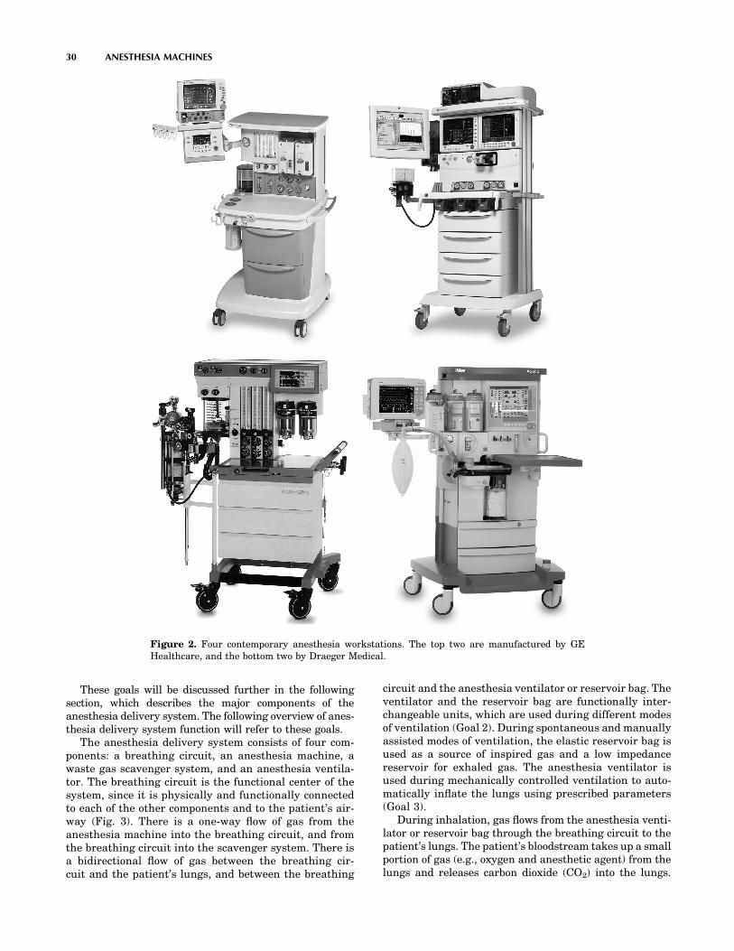
Figure 2. Four contemporary anesthesia workstations. The top two are manufactured by GEHealthcare, and the bottom two by Draeger Medical.

During exhalation, gas flows from the patient’s lungsthrough the breathing circuit back to the anesthesia ven-tilator or reservoir bag. This bulk flow of gas, between thepatient and the ventilator or reservoir bag, constitutes thepatient’s pulmonary ventilation; the volume of each breath isreferred to as tidal volume, and the total volume exchangedduring one minute is referred to as minute volume.
Over time, the patient absorbs oxygen and anestheticagents from, and releases CO2 to, the gas in the breathingcircuit. Without intervention, the gas within the breath-ing circuit would progressively decrease in total volume,oxygen concentration, and anesthetic concentration. Theanesthesia provider, therefore, dispenses fresh gas into thebreathing circuit, replacing the gas absorbed by thepatient. Using the anesthesia machine, the anesthesia pro-vider precisely controls both the flow rate and the concen-tration of various gases in the fresh gas (Goal 1). Theanesthesia machine is capable of delivering a total freshgas flow that far exceeds the volume of gas absorbed by thepatient. When higher fresh gas flows are used (for example,to rapidly change the concentration of gases in the breathingcircuit), the excess gas is vented into the scavenger system tobe evacuated from the operating room (Goal 5).
To conserve the use of anesthetic gases (Goal 4), theanesthesia provider will use a fresh gas flow rate that issignificantly lower than the patient’s minute volume. Inthis situation, the patient reinhales gas that they hadpreviously exhaled into the breathing circuit (this is calledrebreathing). Carbon dioxide absorbent contained withinthe breathing circuit prevents the patient from rebreathingCO2, which would be deleterious. All other gases (oxygen,nitrous oxide, nitrogen, and anesthetic vapors) can berebreathed safely.
During the course of a typical anesthetic, the anesthesiaprovider will use a relatively high fresh gas flow at thebeginning and end of the anesthetic when a rapid change in
anesthetic concentration is desired, and a lower fresh gasflow when little change in concentration is desired. Thetechnique of closed circuit anesthesia refers to the processof adjusting the fresh gas flow to exactly match the amountof gas used by the patient so that no gas is vented to thescavenging system.
Because anesthesia delivery systems provide criticallife support functions to unconscious patients, equipmentmalfunctions and user errors can have catastrophic con-sequences. In 1974, the American National StandardsInstitute published an anesthesia machine standardthat specified minimum performance and safety require-ments for anesthesia gas machines (Goals 6 and 7). Thatstandard was a landmark one, in that it was the firstsystematic approach to standardize the safety require-ments for a medical device. Similar standards have sincebeen written for other medical equipment, and the anes-thesia machine standards have been regularly updated.
Breathing Circuit (Semiclosed Circle System)
The semiclosed circle system is the most commonly usedanesthesia breathing circuit, and the only type that will bediscussed in this article. It is so named because expiredgases can be returned to the patient in a circular fashion(Fig. 4). The components of the circle system include acarbon dioxide absorber canister, two one-way valves, areservoir bag, an adjustable pressure-limiting valve, andtubes that connect to the patient, ventilator, anesthesiamachine, and scavenger system.
During inspiration, the peak flow of gas exceeds 25L�min�1, far in excess of the rate of fresh gas supply. Asa result, the patient will inspire both fresh gas and gasstored in the reservoir bag or ventilator bellows. Inspiredgas travels through the carbon dioxide absorber canister,past the one-way inspiratory valve, to the patient. During
ANESTHESIA MACHINES 31
Figure 3. Block diagram of anesthesia deliverysystem components. The arrows show thedirection of gas flow between components.

exhalation, gas travels from the patient, past the one-wayexpiratory valve, to the reservoir bag (or ventilator bellows,depending upon the position of the bag–ventilator selectorswitch). The one-way valves establish the direction of gasflow in the breathing circuit. Carbon dioxide is notrebreathed because exhaled gas is directed through thecarbon dioxide absorber canister prior to being reinhaled.Fresh gas from the anesthesia machine flows continuouslyinto the breathing circuit. During inhalation, this gas joinswith the inspiratory flow and is directed toward thepatient. During exhalation, the fresh gas enters the breath-ing circuit and travels retrograde through the carbondioxide absorber canister toward the reservoir bag (it doesnot travel toward the patient because the inspiratory one-way valve is closed during exhalation). Thus, during exha-lation, gas enters the reservoir bag from the expiratorylimb and from the carbon dioxide absorber canister. Oncethe reservoir bag is full, excess returning gas is vented outthe adjustable pressure-limiting (APL) valve to the sca-venger system (when the ventilator is used, the excess gasis vented out the ventilator exhaust valve). The total freshgas flow will therefore control the amount of gas that isrebreathed. At high fresh gas flows, the exhaled gases arewashed out through the scavenging system between eachinspiration. At low fresh gas flow, very little exhaled gas is
forced out to the scavenging system and most of the exhaledgas is reinhaled in subsequent breaths.
CIRCLE SYSTEM COMPONENTS
CO2 Absorbents
Alkaline hydroxides of sodium, potassium, calcium, andbarium in varying concentrations are most commonly usedas carbon dioxide absorbents. These alkaline hydroxidesirreversibly react with carbon dioxide to eventually formcarbonates, releasing water and heat. Absorbent granulesare 4- to 8-mesh in size (25–35 granules cm�3) to maximizethe surface area available for chemical reaction and mini-mize the resistance to gas flow through the absorber can-ister. Ethyl violet is incorporated into the granules as a pHindicator; fresh granules are white, while a purple colorindicates that the absorbent needs to be replaced. Absorbercanisters are constructed with transparent sides so thatabsorbent color can be easily monitored during use. Can-isters have a typical capacity of 900–1200 cm3 and theabsorbent is good for �10–30 h of use, depending on theoperating conditions.
Many of the absorbent materials have the potential tointeract with anesthetic agents to degrade the anesthetics
32 ANESTHESIA MACHINES
Figure 4. This schematic of the circle breathing circuit shows the circular arrangement ofcomponents. The one-way valves permit flow in only one direction.

and produce small amounts of potentially toxic gases, suchas carbon monoxide. This is especially true if the absor-bents are allowed to dessicate by exposure to high flows ofdry gas (e.g., leaving the fresh gas flowing on the anesthe-sia machine over a weekend). Periodic replacement ofabsorbent, especially at the end of a weekend is thereforedesirable. Newer absorbent materials, which are morecostly, are designed to reduce or eliminate the potentialfor producing toxic gases by eliminating the hydroxides ofsodium, barium, and potassium.
Unidirectional Valves
The inspiratory and expiratory one-way valves are simple,passive devices. Each has an inlet tube that is capped by avalve disk. When the pressure in the inlet tube exceedsthat in the outlet tube, the valve opens to allow gas to flowdownstream. The valve disks are light in weight to mini-mize gas flow resistance. Each valve has a clear dome toallow visual monitoring of valve function. Rarely, valvesmalfunction by failing to open or close properly. Carbondioxide rebreathing can occur if either valve becomesincompetent (i.e., fails to close properly). This can occurif a valve disk becomes warped, sticks open due to humid-ity, or fails to seat properly.
Reservoir Bag
The reservoir bag is an elastic bag that serves three func-tions in the breathing circuit. First, it is a compliant elementof an otherwise rigid breathing circuit that allows changesin breathing circuit gas volume without changes in breath-ing circuit pressure. Second, it provides a means for manu-ally pressurizing the circuit to control or assist ventilation.Third, it provides a safety limit on the peak pressure thatcan be achieved in the breathing circuit. It acts as a pres-sure-limiting device in the event that fresh gas inflowexceeds APL valve outflow. Reservoir bags are designedsuch that, at fresh gas flow rates below 15 L�min�1, thebreathing circuit pressure will remain < 35 cm H2O (3.4kPa) until the bag reaches more than twice its full capacity.Yet, inspiratory pressures up to 70 cm H2O (6.9 kPa) can beachieved by quickly compressing the reservoir bag.
APL Valve
The APL valve (euphemistically referred to as the pop-offvalve) is a spring-loaded device that controls the flow of gasfrom the breathing circuit to the scavenger system. Thevalve opens when the pressure gradient from the circuit tothe scavenger exceeds the force exerted by the spring (asdiscussed later, the pressure in the scavenger system isregulated to be equal to atmospheric pressure plus orminus a few cm H2O). When the patient is breathingspontaneously, the anesthesia practitioner minimizes thespring tension allowing the valve to open with minimalend-expiratory pressure (typically < 3 cm H2O, or 0.3 kPa).When the anesthesia practitioner squeezes the reservoir bagto manually control or assist ventilation, the APL valveopens during inhalation. Part of the gas exiting the reservoirbag escapes to the scavenger system and the remainderis directed toward the patient. By turning a knob, the
anesthesia practitioner increases the pressure on the springso that the APL valve remains closed until the pressure inthe circuit achieves a level that is adequate to inflate thepatients lungs; the APL valve thus opens toward the end ofinhalation, once the lungs are adequately inflated. Contin-ual adjustment of the APL valve is sometimes needed toadapt to changing fresh gas flow rate, circuit leaks, pulmon-ary mechanics, and ventilation parameters.
Bag–Ventilator Selector Switch
During mechanical ventilation, the reservoir bag and APLvalve are disconnected from the breathing circuit andan anesthesia ventilator is connected to the same spot.Modern breathing circuits have a selector switch thatquickly toggles the connection to either the ventilatoror the reservoir bag and APL valve.
VIRTUES AND LIMITATIONS OF THE CIRCLE BREATHINGCIRCUIT
Primary advantages of the circle breathing system overother breathing circuits include conservation of anestheticgases and vapors, ease of use, and humidification andheating of inspired gases.
As stated previously, anesthetic agents are conservedwhen very low fresh gas flows are used with the circlebreathing system. The minimum adequate flow is one thatjust replaces the gases taken up by the patient; for a normaladult, flows below 0.5 L�min�1 can be achieved duringanesthesia maintenance. It is customary to use higherfresh gas flow rates in the range of 1–2 L�min�1, but thisis still well below typical minute ventilation rates of 5–10L�min�1 which is the fresh gas flow that would be requiredfor a nonrebreathing ventilation system.
The circle breathing circuit is easy to use because thesame fresh gas settings can be used with patients of varioussizes. A 100 kg adult and a 1 kg infant can each beanesthetized with a circle breathing system and a freshgas maintenance flow rate of 1–2 L�min�1. Since the largerpatient would take up more anesthetic agent and moreoxygen, and would give off more carbon dioxide, higherminimal flows would be required for the larger patient andthe carbon dioxide absorbent would become exhaustedquicker. Also, for convenience, a smaller reservoir bagand smaller bore breathing tubes would be selected forthe smaller patient. But, otherwise, the system wouldfunction similarly for both patients.
Humidification and warming of inspired gases isanother advantage of rebreathing. Fresh gas is mixed fromcompressed gases that contain zero water vapor, andbreathing this dry gas can have detrimental effects on lungfunction. But, within the circle breathing system, inspiredgas is humidified by the admixture of rebreathed gas, andby the water vapor that forms as a byproduct of carbondioxide absorption. Both of these mechanisms also act towarm the inspired gas. By using low flows, enough heatand humidity is conserved to eliminate the need to activelyheat and humidify inspired gas.
Most disadvantages of the circle breathing system are dueto the large circuit volume. Internal volumes are primarily
ANESTHESIA MACHINES 33

determined by the sizes of the absorbent canister, reservoirbag, and breathing hoses; 3–6 L are typical. Large circuits arephysically bulky. They also increase the time required tochange inspired gas concentrations because the large reservoirof previously exhaled gas is continually added to fresh gas.Finally, large circuits are more compliant, which degradesthe efficiency and accuracy of ventilation. This effect willbe discussed further in the section on ventilators.
Anesthesia Machine
The anesthesia machine is used to accurately deliver intothe breathing circuit a precise flow and concentration ofgases and vapors. Anesthesia machines are manufacturedto deliver various compressed gases; all deliver oxygen,most deliver nitrous oxide or air, some deliver helium orcarbon dioxide. They have one or more vaporizers thatconvert liquid anesthetic agents into anesthetic vapors;currently used inhaled vapors include halothane, enflur-ane, isoflurane, sevoflurane, and desflurane. Anesthesiamachines include numerous safety features that alert theanesthesia provider to malfunctions and avert useerrors.
The anesthesia machine is a precision gas mixer (Fig. 5).Compressed gases enter the machine from the hospital’scentralized pipeline supply or from compressed gas cylin-ders. The compressed gases are regulated to specifiedpressures, and each passes through its own flow controllerand flow meter assembly. The compressed gases then aremixed together and may flow through a single vaporizerwhere anesthetic vapor is added. The final gas mixturethen exits the common gas outlet (also called the fresh gasoutlet) to enter the breathing circuit.
ANESTHESIA MACHINE COMPONENTS
Compressed Gas Inlets
Compressed gases from the hospital pipeline system orfrom large compressed gas cylinders enter theanesthesia machine through flexible hoses. The inlet con-nector for each gas is unique in shape to prevent theconnection of the wrong supply hose to a given inlet.The standardized design of each hose-inlet connector pairconforms to the Diameter Indexed Safety System (DISS)(9).
34 ANESTHESIA MACHINES
Figure 5. Schematic showing the internal piping and placement of components within theanesthesia machine. Dark gray indicates oxygen (O2) and light gray indicates nitrous oxide (N2O).
Anesthesia machines also have inlet yokes that holdsmall compressed gas cylinders; these cylinders providecompressed gas for emergency backup and for use in loca-tions without piped gases. Each yoke is designed to preventincorrect placement of a cylinder containing another gas.Two pins located in the yoke must insert into correspond-ing holes on the cylinder valve stem. The standardizedplacement of these pins and corresponding holes, referredto as the Pin Indexed Safety System (PISS), is unique foreach gas (10).
Pressure Regulators And Gauges
Gauges on the front panel of the anesthesia machine dis-play the cylinder and pipeline inlet pressures of each gas.Gases from the pipeline inlets enter the anesthesiamachine at pressures of 45–55 psig (310–380 kPa), whereasgases from the compressed gas cylinders enter at pressuresup to 2000 psig (1379 kPa). (Pressure conversion factors:1 psig ¼ 0.068 atm ¼ 51.7 mmHg ¼ 70.3 cm H2O ¼6.89 kPa.) Pressure regulators on each cylinder gas inletline reduce the pressure from each cylinder to � 45 psig(310 kPa). The pressure regulators provide a relativelyconstant outlet pressure in the presence of a variable inletpressure, which is important since the pressure within agas cylinder declines during use. Lines from the pipelineinlet and the cylinder inlet (downstream of the pressureregulator) join to form a common source line for each gas.Gases are preferentially used from the pipelines, since thepressure regulators are set to outlet pressures that are lessthan the usual pipeline pressures.
Flow Controllers And Meters
A separate needle-valve controls the flow rate of eachcompressed gas. Turning a knob on the front panel ofthe anesthesia machine counterclockwise opens the needlevalve and increases the flow; turning it clockwise decreasesor stops the flow. A flowmeter assembly, located above eachflow-control knob, shows the resulting flow rate. The flow-meter consists of a tapered glass tube containing a movablefloat; the internal diameter of the tube is larger at the topthan at the bottom. Gas flows up through the tube, which isvertically aligned, and in doing so blows the float higher inthe tube. The float balances in midair partway up the tubewhen its weight equals the force of the gas travelingthrough the space between the float and the tube. Thus,the height to which the float rises within the tube isproportional to the flow rate of the gas. Flow rate isindicated by calibrated markings on the tube alongsidethe level of the float.
Each flowmeter assembly is calibrated for a specific gas.The density and viscosity of the gas significantly affects theforce generated in traveling through the variable-sizedannular orifice created by the outer edge of the float andthe inner surface of the tube. Temperature and barometricpressure affect gas density, and major changes in eithercan alter flowmeter accuracy. Accuracy is also impaired bydirt or grease within the tube, static electricity betweenthe float and the tube, and nonvertical alignment of thetube.
To increase precision and accuracy, some machinesindicate gas flow rate past a single needle valve usingtwo flowmeter assemblies, one for high flows and the otherfor low flows. These flowmeters are connected in series andthe flow rate is indicated on one flowmeter or the other. Aflow rate below the range of the high-flow meter shows anaccurate flow rate on the low flow meter and an unreadablelow flow rate on the high flow meter. While, a flow rate thatexceeds the range of the low-flow meter shows an accurateflow rate on the high flow meter and an unreadable highflow rate on the low flow meter.
Each gas, having passed through its individual flowcontroller and meter assembly, passes into a commonmanifold before continuing on. Only the individual gasflow rates are indicated on the flowmeters; the user mustcalculate the total gas flow rate and the percent concentra-tion of each gas in the mixture.
Vaporizers
Vaporizers are designed to add an accurate amount ofvolatilized anesthetic to the compressed gas mixture. Anes-thetic vapors are pharmacologically potent, so low concen-trations (generally < 5%) are typically needed. Thevolatilized gases contribute to the total gas flow rate anddilute the concentration of the other compressed gases. Theuser can calculate these effects since they are not displayedon the machine front panel; luckily, these are generallynegligible and can be ignored. Even though most anesthe-sia machines have multiple vaporizers, only one is used at atime; interlock mechanisms prevent a vaporizer from beingturned on when another vaporizer is in use. Vaporizers areanesthetic agent specific and keyed filling systems preventfilling a vaporizer with the wrong liquid anesthetic.
All current anesthesia machines have direct-settingvaporizers that add a specified concentration of a singleanesthetic vapor to the compressed gas mixture. Variable-bypass vaporizers are the most common (Fig. 6). In these,the inflowing compressed gas mixture is split into twostreams. One stream is directed through a bypass channeland the other is directed into a chamber within the vapor-izer that contains liquid anesthetic agent. The gas enteringthe vaporizing chamber becomes saturated with anestheticvapor at a concentration that depends on the vapor pres-sure of the particular liquid anesthetic. For example, sevo-flurane has a vapor pressure of 157 mmHg (20.9 kPa) at20 8C, so the gas within the vaporizing chamber is about20% sevoflurane (at sea level). This highly concentratedanesthetic mixture exits the chamber (now, at a flow rategreater than that entering the chamber, due to the additionof anesthetic vapor) to join, and be diluted by, gas thattraversed the bypass channel. A dial on the vaporizercontrols the delivered anesthetic concentration by regu-lating the resistance to flow along each path. For example,setting a sevoflurane vaporizer to a dialed concentrationof 1% splits the inflowing compressed gas mixture so thatone-twenty-fourth of the total is directed through thevaporizing chamber and the remainder is directed throughthe bypass. Direct-reading variable-bypass vaporizers arecalibrated for a specific agent, since each anesthetic liquidhas a different vapor pressure. Vapor pressure varies with
ANESTHESIA MACHINES 35

temperature, so vaporizers are temperature compensated;at higher temperatures, a temperature sensitive valve divertsmore gas through the bypass channel. Vaporizers aredesigned to ensure that the gas within the liquid-containingchamber is saturated with anesthetic vapor. A cottonwick within the chamber promotes saturation by increas-ing the surface area of the liquid. Thermal energy isrequired for liquid vaporization (heat of vaporization).To minimize cooling of the anesthetic liquid, vaporizersare constructed of metals with high specific heat andhigh thermal conductivity so that heat is transferred easilyfrom the surroundings. The output of variable-bypassvaporizers varies with barometric pressure; delivered con-centration increases as barometric pressure decreases.
Desflurane vaporizers are designed differently becausedesflurane has such a high vapor pressure (664 mmHg,or 88.5 kPa, at 20 8C) and low boiling point (22.8 8C).Uncontrollably high output concentrations could easilyoccur if desflurane were administered at room temperaturefrom a variable-bypass vaporizer. In a desflurane vaporizer,the liquid desflurane is electrically heated to a controlledtemperature of 39 8C within a pressure-tight chamber. Atthis temperature, the vapor pressure of desflurane is 1500mmHg (200 kPa) and the anesthetic vapor above the liquidis a compressed gas. The concentration dial on the vaporizerregulates a computer-assisted flow proportioning mechan-
ism that meters pressurized desflurane into the incominggas mixture to achieve a set output concentration of des-flurane vapor. Room temperature does not affect the outputconcentration of the vaporizer, nor does barometric pres-sure. The vaporizer requires electrical power for the heater,the onboard computer, and two electronic valves.
Safety Systems
By written standard, the anesthesia machine has numer-ous safety systems designed to prevent use errors. Some ofthese, such as the DISS and PISS systems to preventcompressed gas misconnections, interlock mechanisms toprevent simultaneous use of multiple vaporizers, andkeyed filler systems to prevent misfilling of vaporizers,have already been discussed. Others are presented, below.
Failsafe Mechanism And Oxygen Alarm. The anesthesiamachine has a couple of safety systems that alert the userand stop the flow of other gases when the oxygen supplyruns out (for example, when an oxygen tank becomesdepleted). An auditory alarm sounds and a visual messageappears to alert the user when the oxygen supply pressurefalls below a predetermined threshold pressure of � 30 psig(207 kPa). A failsafe valve in the gas line supplying eachflow controller-meter assembly, except oxygen, stops the
36 ANESTHESIA MACHINES
Figure 6. Schematic of a variable-bypass vaporizer. Arrows indicate direction of gas flow; heavierarrows indicate larger flow rates. Gas enters the Inlet Port and is split at the Bypass Cone into twostreams. One stream is directed through a bypass channel and the rest enters the VaporizingChamber. Gas entering the Vaporizing Chamber equilibrates with Liquid Anesthetic Agent tobecome saturated with Anesthetic Vapor. This concentrated anesthetic mixture exits the chamber tojoin, and be diluted by, gas that traversed the bypass channel. The Concentration Control Dial isattached to the Concentration Cone, which regulates resistance to flow exiting the VaporizingChamber and thus controls the anesthetic concentration dispensed from the Outlet Port.

flow of other gases. The failsafe valve is either an on–offvalve or a pressure-reducing valve that is controlled by thepressure within the oxygen line. When the oxygen supplypressure falls below the threshold level, the failsafe valvesclose to stop the flow, or proportionally reduce the supplypressure, of all the other gases. This prevents administra-tion of hypoxic gases (e.g., nitrous oxide, helium, nitrogen,carbon dioxide) without oxygen, which could rapidly causeinjury to the patient, but it also prevents administration ofair without oxygen. The failsafe mechanisms do not pre-vent delivery of hypoxic gas mixtures in the presence ofadequate oxygen supply pressure; the gas proportioningsystem, described below, prevents this.
Gas Proportioning System. Anesthesia machines areequipped with proportioning systems that prevent thedelivery of high concentrations of nitrous oxide, the mostcommonly used non-oxygen containing gas. A mechanicalor pneumatic link between the oxygen and nitrous oxidelines ensures that nitrous oxide does not flow without anadequate flow of oxygen. One such mechanism, the Datex-Ohmeda Link-25 system, is a chain linkage betweensprockets on the nitrous oxide and oxygen flow needlevalves. The linkage is engaged whenever the nitrous oxideis set to exceed three-times the oxygen flow, or when theoxygen flow is set to less than one-third of the nitrousoxide flow; this limits the nitrous oxide concentration to amaximum of 75% in oxygen. Another mechanism, theDraeger Oxygen Ratio Monitor Controller (ORMC), is aslave flow control valve on the nitrous oxide line that ispneumatically linked to the oxygen line. This systemlimits the flow of nitrous oxide to a maximum concentra-tion of 72 � 3% in oxygen. Both of the above systemscontrol the ratios of nitrous oxide and oxygen, but donot compensate for other gases in the final mixture; ahypoxic mixture (oxygen concentration < 21%) could bedispensed, therefore, if a third gas were added in signifi-cant concentrations.
Oxygen Flush. Each anesthesia machine has an oxygenflush system that can rapidly deliver 45–70 L�min�1 ofoxygen to the common gas outlet. The user presses theoxygen flush valve in situations where high flow oxygen isneeded to flush anesthetic agents out of the breathingcircuit, rapidly increase the inhaled oxygen concentration,or compensate for a large breathing circuit leak (for exam-ple, during positive pressure ventilation of the patient witha poorly fitted face mask). The oxygen flush system alsoserves as a safety system because it bypasses most of theinternal plumbing of the anesthesia machine (e.g., safetycontrol valves, flow controller-meter assemblies, andvaporizers) and because it is always operational, evenwhen the anesthesia machine’s master power switch is off.
Monitors and User-Interface Features. Written stan-dards specify that all anesthesia machines must beequipped with essential safety monitors and user-interfacefeatures. To protect against hypoxia, each has an inte-grated oxygen analyzer that monitors the oxygen concen-tration in the breathing circuit whenever the anesthesiamachine is powered on. The oxygen monitor must have an
audible alarm that sounds whenever the oxygen concen-tration falls below a preset threshold, which cannot beset < 18%. To protect against dangerously high and lowairway pressures, the breathing circuit pressure is con-tinuously monitored by an integrated system that alarmsin the event of sub-atmospheric airway pressure, sustainedhigh airway pressure, or extremely high airway pressure.To protect against ventilator failure and breathing circuitdisconnections, the breathing circuit pressure is monitoredto ensure that adequate positive pressure is generated atleast a few times a minute whenever the ventilator ispowered on; a low airway pressure alarm (AKA disconnectalarm) is activated whenever the breathing circuit pres-sure does not reach a user-set threshold level over a 15 sinterval. User-interface features protect against mistakesin gas flow settings. Oxygen controls are always positionedto the right of other gas flow controls. The oxygen flowcontrol knob has a unique size and shape that is differentfrom the other gas control knobs. The flow control knobsare protected against their being bumped to prevent acci-dental changes in gas flow rates. All gas flow knobs andvaporizer controls uniformly increase their settings whenturned in a clockwise direction.
LIMITATIONS
Anesthesia machines are generally reliable and problem-free. Limitations include that they require a source ofcompressed gases, are heavy and bulky, are calibrated tobe accurate at sea level, and are designed to function in anupright position within a gravitational field. Machine mal-functions are usually a result of misconnections or discon-nections of internal components during servicing ortransportation. Aside from interlock mechanisms thatdecrease the likelihood of wrong gas or wrong anestheticagent problems, there are no integrated monitors to ensurethat the vaporizers are filled with the correct agents andthe flow meters are dispensing the correct gases. Likewise,except for oxygen, the gas supply pressures and anestheticagent levels are not automatically monitored. Thus, pro-blems can still result when the anesthesia provider fails todiagnose a problem with the compressed gas or liquidanesthetic supplies.
Ventilator
General anesthesia impairs breathing by two mechanisms,it decreases the impetus to breath (central respiratorydepression), and it leads to upper airway obstruction. Addi-tionally, neuromuscular blockers, which are often adminis-tered during general anesthesia, paralyze the muscles ofrespiration. For these reasons, breathing may be supportedor controlled during anesthesia to ensure adequate minuteventilation. The anesthesia provider can create intermittentpositive pressure in the breathing circuit by rhythmicallysqueezing the reservoir bag. Ventilatory support is oftenprovided in this way for short periods of time, especiallyduring the induction of anesthesia. During mechanicalventilation, a selector switch is toggled to disconnect thereservoir bag and APL valve from the breathing circuitand connect an anesthesia ventilator instead. Anesthesia
ANESTHESIA MACHINES 37
ventilators provide a means to mechanically control ventila-tion, delivering consistent respiratory support for extendedperiods of time and freeing the anesthesia provider’s handsand attention for other tasks. Most surgical patients havenormal pulmonary mechanics and can be adequately venti-lated with an unsophisticated ventilator designed for ease ofuse. But, high performance anesthesia ventilators allow safeand effective ventilation of a wide variety of patients,including neonates and the critically ill.
Most anesthesia ventilators are pneumatically pow-ered, electronically controlled, and time cycled. All canbe set to deliver a constant tidal volume at a constant rate(volume control). Many can also be set to deliver a constantinspiratory pressure at a constant rate (pressure control).All anesthesia ventilators allow spontaneous patientbreaths between ventilator breaths (intermittent manda-tory ventilation, IMV), and all can provide PEEP duringpositive pressure ventilation (note that in some oldersystems PEEP is set using a PEEP-valve integrated intothe expiratory limb of the breathing circuit, and is notactively controlled by the ventilator). In general, anesthe-sia ventilators do not sense patient effort, and thus do notprovide synchronized modes of ventilation, pressure sup-port, or continuous positive airway pressure (CPAP).
As explained above, the anesthesia delivery system con-serves anesthetic gases by having the patient rebreathepreviously exhaled gas. Unlike intensive care ventilators,which deliver new gas to the patient during every breath,anesthesia ventilators function as a component of theanesthesia delivery system and maintain rebreathing dur-ing mechanical ventilation. In most anesthesia ventilators,this is achieved by incorporating a bellows assembly (seeFig. 4). The bellows assembly consists of a distensible bel-lows that is housed in a clear rigid chamber. The bellows isfunctionally equivalent to the reservoir bag; it is attached to,and filled with gas from, the breathing circuit. Duringinspiration, the ventilator injects drive gas into the rigidchamber; this squeezes the bellows and directs gas from thebellows to the patient via the inspiratory limb of the breath-ing circuit. The drive gas, usually oxygen or air, remainsoutside of the bellows and never enters the breathing circuit.During exhalation, the drive gas within the rigid chamber isvented to the atmosphere, and the patient exhales intothe bellows through the expiratory limb of the breathingcircuit.
The bellows assembly also contains an exhaust valvethat vents gas from the breathing circuit to the scavengersystem. This ventilator exhaust valve serves the samefunction during mechanical ventilation that the APL valveserves during manual or spontaneous ventilation.However, unlike the APL valve, it is held closed duringinspiration to ensure that the set tidal volume dispensedfrom the ventilator bellows is delivered to the patient.Excess gas then escapes from the breathing circuit throughthis valve during exhalation.
The tidal volume set on an anesthesia ventilator is notaccurately delivered to the patient; it is augmented by freshgas flow from the anesthesia machine, and reduced due tocompression-loss within the breathing circuit. Fresh gas,flowing into the breathing circuit from the anesthesiamachine, augments the tidal volume delivered from the
ventilator because the ventilator exhaust valve, which isthe only route for gas to escape from the breathing circuit, isheld closed during inspiration. For example, at a fresh gasflow rate of 3 L�min�1 (50 mL�s�1), and ventilator settings of10 breaths min�1 and an I/E ratio of 1:2 (inspiratorytime ¼ 2 s), the delivered tidal volume is augmented by100 mL per breath (2 s per breath � 50 mL�s�1). Conversely,the delivered tidal volume is reduced due to compressionloss within the breathing circuit. The magnitude of this lossdepends on the compliance of the breathing circuit and thepeak airway pressure. Circle breathing circuits typicallyhave a compliance of 7–9 mL�cm�1 H2O (70–90 mL�kPa�1),which is significantly higher than the typical 1–3 mL�cm�1
H2O (10–30 mL�kPa�1) circuit compliance of intensive careventilators, because of their large internal volume. For exam-ple, when ventilating a patient with a peak airway pressureof 20 cm H2O (2 kPa) using an anesthesia ventilator with abreathing circuit compliance of 10 mL�cm H2O, deliveredtidal volume is reduced by 200 mL per breath.
LIMITATIONS
Until recently, anesthesia ventilators were simple devicesdesigned to deliver breathing circuit gas in volume controlmode. The few controls consisted of a power switch, anddials to set respiratory rate, inspiratory/expiratory (I/E)ratio, and tidal volume. While simple to operate, theseventilators had a number of limitations. As discussedabove, delivered tidal volume was altered by peak airwaypressure and fresh gas flow rate. Tidal volume augmenta-tion was particularly hazardous with small patients, suchas premature infants and neonates, since increasing thegas flow on the anesthesia machine could unintentionallygenerate dangerously high tidal volumes and airway pres-sures. Tidal volume reduction was particularly hazardoussince dramatically lower than set tidal volumes could bedelivered, unbeknown to the provider, to patients requir-ing high ventilating pressures (e.g., those with severe air-way disease or respiratory distress syndrome). Worse yet,the pneumatic drive capabilities of these ventilators weresometimes insufficient to compensate for tidal volumelosses due to compression within the breathing circuit;anesthesia ventilators were unable to adequately ventilatepatients with high airway pressures (> 45 cm H2O) requir-ing large minute volumes (> 10 L�min�1). Another imper-fection of anesthesia ventilators is that they arepneumatically powered by compressed gases. The ventila-tor’s rate of compressed gas consumption, which is approxi-mately equal to the set minute volume (5–10 L�min�1 in anormal size adult), is not a concern when central com-pressed gas supplies are being used. But the ventilator canrapidly deplete oxygen supplies when compressed gas isbeing dispensed from the emergency backup cylindersattached to the anesthesia machine (e.g., a backup cylindercould provide over 10 h of oxygen to a breathing circuitat low flow, but would last only one-hour if also poweringthe ventilator). Lastly, anesthesia ventilators that do notsense patient effort are unable to provide synchronized orsupportive modes of ventilation. This limitation is mostsignificant during spontaneous ventilation, since CPAPand pressure support cannot be provided to compensate
38 ANESTHESIA MACHINES

for the additional work of breathing imposed by the breath-ing circuit and endotracheal tube, or to prevent the lowlung volumes and atalectasis that result from generalanesthesia. New anesthesia ventilators, introduced inthe past 10 years, address many of these limitations asdiscussed later in the section on New Technologies.
Scavenger System
Waste anesthetic gases are vented from the operatingroom to prevent potentially adverse effects on healthcare workers. High volatile anesthetic concentrations inthe operating room atmosphere can cause problems suchas headaches, dysphoria, and impaired psychomotorfunctioning; chronic exposure to trace levels has beenimplicated as a causative factor for cancer, spontaneousabortions, neurologic disease, and genetic malformations,although many studies have not borne out these effects.The National Institute for Occupational Safety andHealth (NIOSH) recommends that operating room levelsof halogenated anesthetics be < 2 parts per million (ppm)and that nitrous oxide levels be < 25 ppm. Waste gases canbe evacuated from the room actively via a centralvacuum system, or passively via a hose to the outside;alternatively, the waste gas can pass through a canistercontaining activated charcoal, which absorbs halogenatedanesthetics.
The scavenger system is the interface between the eva-cuation systems described in the preceding sentence and theexhaust valves on the breathing circuit and ventilator (i.e.,APL valve and ventilator exhaust valve). It functions as areservoir that holds waste gas until it can vent to theevacuation system. This is necessary because gas exits theexhaust valves at a non-constant rate that may, at times,exceed the flow rate of the evacuation system. The scavengersystem also ensures that the downstream pressure on theexhaust valves does not become too high or too negative.Excessive pressure at the exhaust valve outlet could causesustained high airway pressure leading to barotrauma andcardiovascular collapse; whereas, excessive vacuum at theexhaust valve outlet could cause sustained negative airwaypressure leading to apnea and pulmonary edema.
There are two categories of scavenger systems, open andclosed. Open scavenger systems can only be used with avacuum evacuation system. In an open scavenger system,waste gas enters the bottom of a rigid reservoir that is opento the atmosphere at the top, and gas is constantly evac-uated from the bottom of the reservoir into the vacuum.Room air is entrained into the reservoir whenever thevacuum flow rate exceeds the waste gas flow rate, andgas spills out to the room through the openings in thereservoir whenever the waste gas flow rate exceeds thevacuum flow rate. The arrangement of the componentsprevents spillage of waste gas out of the reservoir openingsunless the average vacuum flow rate is less than theaverage flow out of the exhaust valves.
Closed scavenger systems consist of a compliant reser-voir bag with an inflow of waste gas from the exhaustvalves of the breathing system and an outflow to the activeor passive evacuation system. Two or more valves regulatethe internal pressure of the closed scavenger system. A
negative pressure release valve opens to allow entry ofroom air whenever the pressure within the system becomestoo negative, < �1.8 cm H2O (�0.18 kPa) (i.e., in situationswhere the evacuation flow exceeds the exhaust flow and thereservoir bag is collapsed). A positive pressure releasevalve opens to allow venting of waste gas to the roomwhenever the pressure within the scavenger systembecomes too high, > 5 cm H2O (0.5 kPa) (i.e., in situationswhere the reservoir bag is full and the exhaust flow exceedsthe evacuation flow). Thus, the pressure within the scaven-ger system is maintained between �1.8 and 5.0 cm H2O.
Integrated Monitors
All anesthesia delivery systems have integrated electronicsafety monitors intended to avert patient injuries. Includedare (1) an oxygen analyzer, (2) an airway pressure monitor,and (3) a spirometer.
The oxygen analyzer measures oxygen concentration inthe inspiratory limb of the breathing circuit to guardagainst the administration of dangerously low inhaledoxygen concentrations. Most analyzers use a polarographicor galvanic (fuel cell) probe that senses the rate of anoxygen-dependent electrochemical reaction. These ana-lyzers are inexpensive and reliable, but are slow toequilibrate to changes in oxygen concentration (responsetimes on the order of 30 s). They also require dailycalibration. Standards stipulate that the oxygen analyzerbe equipped with an alarm, and be powered-on wheneverthe anesthesia delivery system is in use.
The airway pressure monitor measures pressure withinthe breathing circuit, and warns of excessively high ornegative pressures. It also guards against apnea duringmechanical ventilation. Most anesthesia delivery systemshave two pressure gauges: an analog Bourdon tube pres-sure gauge that displays instantaneous pressure on amechanical dial, and an electronic strain-gauge monitorthat displays a pressure waveform. Most electronic pressuremonitors embody an alarm system with variable-thresholdnegative pressure, positive pressure, and sustained pres-sure alarms that can be adjusted by the user. An apneaalarm feature, which is enabled whenever the ventilator ispowered-on, ensures that positive pressure is sensed withinthe breathing circuit at regular intervals. On some anesthe-sia delivery systems pressure is sensed within the circlesystem absorber canister; on other systems it is sensed onthe patient side of the one-way valves; the latter gives a moreaccurate reflection of airway pressure.
The spirometer measures gas flow in the expiratory limbof the breathing circuit and guards against apnea anddangerously low or high respiratory volumes. A numberof different techniques are commonly used to measure flow.These include spinning vanes, rotating sealed spirometers,ultrasonic, and variable orifice differential pressure.Respiratory rate, tidal volume, and minute volume arederived from the sensor signals and displayed to the user.Some machines also display a waveform of exhaled flowversus time. Most spirometers have an alarm system withvariable-threshold alarms for low and high tidal volume, aswell as an apnea alarm that is triggered if no flow isdetected during a preset interval.
ANESTHESIA MACHINES 39

In addition to these standard monitors, some anesthesiaworkstations have integrated gas analyzers that measureinhaled and exhaled concentrations of oxygen, carbon diox-ide, nitrous oxide, and volatile anesthetic agents. Althoughstand-alone gas analyzers are available, they are likely to beintegrated into the anesthesia workstation because theymonitor gas concentrations and respiratory parameters thatare controlled by the anesthesia delivery system.
Other patient monitors, such as electrocardiography,pulse oximetry, invasive and noninvasive blood pressure,and thermometry may also be integrated into the anesthesiaworkstation; but often stand-alone monitors are placed onthe shelves of the anesthesia delivery system. In either case,standard patient monitors must be used during the conductof any anesthetic to evaluate the adequacy of the patient’soxygenation, ventilation, circulation, and body temperature.Monitoring standards, which have contributed to the dra-matic increase in anesthesia safety, were initially publishedby the American Society of Anesthesiologists in 1986 andhave been continually evaluated and updated (8).
New Technologies
The anesthesia delivery system as described thus far hasevolved incrementally from a pneumatic device designed in1917, by Henry Boyle for administration of anesthesia usingoxygen, nitrous oxide and ether. The evolution of Boyle’smachine has occurred in stages. In the 1950s and 1960s thefailsafe devices and fluidic controlled ventilators were added.In the 1970s and early 1980s the focus was on improvingsafety with features, such as gas proportioning systems,safety alarms, electronically controlled ventilators, and stan-dardization of the user interface to decrease errors. In the late1980s and 1990s, monitors and electronic recordkeeping wereintegrated to create anesthesia workstations. Since 2000 thefocus has been on improving ventilator performance, incor-porating automated machine self-checks, and transitioningto electronically controlled and monitored flow meters andvaporizers. Some of the new technologies that have beenintroduced in the last few years are discussed, below.
BREATHING CIRCUIT
As discussed above, the tidal volume set on an anesthesiaventilator is not accurately delivered to the patient becauseof two breathing circuit effects. First, a portion of the volumedelivered from the ventilator is compressed within thebreathing circuit and does not reach the patient. Second,fresh gas flowing into the breathing circuit augments thedelivered tidal volume. A number of techniques are used tominimize these effects in new anesthesia delivery systems.
Two techniques have been used to minimize the effect ofgas compression. First, smaller, less compliant breathingcircuits are being used. This has been achieved by mini-mizing the use of compliant hoses between the ventilatorand breathing circuit and by decreasing the size of theabsorber canister. A tradeoff is that the absorbent must bechanged more frequently with a smaller canister, hencenew breathing circuits are designed so that the carbondioxide absorbent can be exchanged during use. Second,many new machines automatically measure breathing
circuit compliance during an automated preuse checkoutprocedure and then compensate for breathing circuit com-pliance during positive pressure ventilation; the ventilatorcontinually senses airway pressure and delivers additionalvolume to make up for that lost to compression.
A number of techniques have also been used to eliminateaugmentation of tidal volume by fresh gas flowing into thecircuit. In one approach, the ventilator automatically adjustsits delivered volume to compensate for the influx of fresh gasinto the breathing circuit. The ventilator either adjusts tomaintain a set exhaled tidal volume as measured by a spi-rometer in the expiratory limb of the breathing circuit, or itresponds to maintain a set inhaled tidal volume sensed in theinspiratory limb, or it modifies its delivered volume based onthe total fresh gas flow as measured by electronic flowmetersin the anesthesia machine. None of the above methodsrequires redesign of the breathing circuit, except for theaddition of flow sensors that communicate with the ventilator.
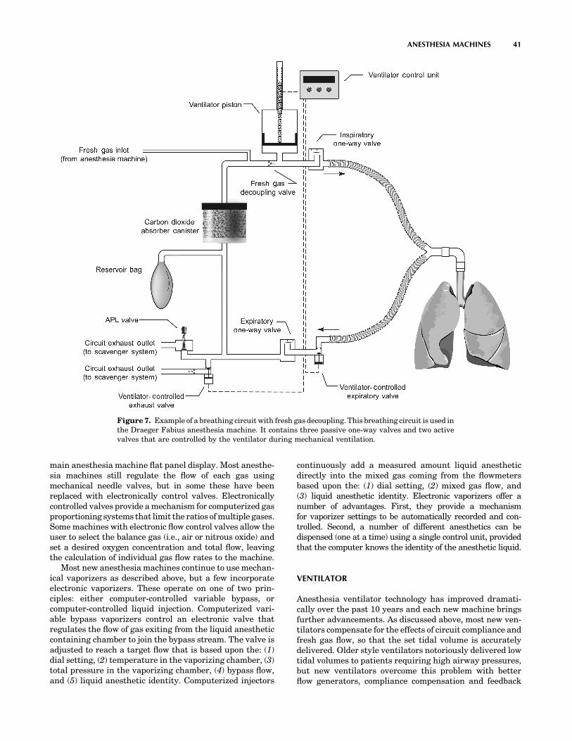
In a radically different approach, called fresh gas decou-pling, the breathing circuit is redesigned so that freshgas flow is channeled away from ventilator-delivered gasduring inspiration, which removes the augmenting effectof fresh gas flow on tidal volume. An example of such abreathingcircuit is illustrated inFig.7. In thiscircuit, duringinhalation, gas dispensed from a piston driven ventilatortravels directly to the patient’s lungs; retrograde flow isblocked by a passive fresh gas decoupling valve, and expira-tory flow is blocked by the ventilator-controlled expiratoryvalve, which is actively closed during the inspiratory phase.Fresh gas does not contribute to the delivered tidal volume;instead it flows retrograde into a nonpressurized portionof the breathing circuit. During exhalation, the ventilator-controlled expiratory valve opens, and the ventilator pistonwithdraws to actively fill with a mixture of fresh gas and gasfrom the reservoir bag. This design causes a number of otherfunctional changes. First, the breathing circuit compliance islower during positive pressure ventilation, since only partof the breathing circuit is pressurized during inspiration(the volume between the fresh gas decoupling valve andthe ventilator-controlled expiratory valve). Second, thereservoir bag remains in the circuit during mechanicalventilation. As a result, it fills and empties with gasthroughout the ventilator cycle, which is an obvious con-trast to the absence of bag movement during mechanicalventilation with a conventional circle breathing circuit.
ANESTHESIA MACHINE
Many new anesthesia machines have electronic gas flowsensors instead of tapered glass tubes with internal floats.Advantages include (1) improved reliability and reducedmaintenance; (2) improved precision and accuracy at low-flows; and (3) ability to automatically record and use gasflows (for instance to adjust the ventilator). The electronicsensors operate on the principle of heat transfer, measur-ing the energy required to maintain the temperature of aheated element in the gas flow pathway. Each sensor iscalibrated for a particular gas, since every gas has adifferent specific heat index. Gas flows are shown ondedicated light-emitting diode (LED) displays or on the
40 ANESTHESIA MACHINES
main anesthesia machine flat panel display. Most anesthe-sia machines still regulate the flow of each gas usingmechanical needle valves, but in some these have beenreplaced with electronically control valves. Electronicallycontrolled valves provide a mechanism for computerized gasproportioning systems that limit the ratios of multiple gases.Some machines with electronic flow control valves allow theuser to select the balance gas (i.e., air or nitrous oxide) andset a desired oxygen concentration and total flow, leavingthe calculation of individual gas flow rates to the machine.
Most new anesthesia machines continue to use mechan-ical vaporizers as described above, but a few incorporateelectronic vaporizers. These operate on one of two prin-ciples: either computer-controlled variable bypass, orcomputer-controlled liquid injection. Computerized vari-able bypass vaporizers control an electronic valve thatregulates the flow of gas exiting from the liquid anestheticcontaining chamber to join the bypass stream. The valve isadjusted to reach a target flow that is based upon the: (1)dial setting, (2) temperature in the vaporizing chamber, (3)total pressure in the vaporizing chamber, (4) bypass flow,and (5) liquid anesthetic identity. Computerized injectors
continuously add a measured amount liquid anestheticdirectly into the mixed gas coming from the flowmetersbased upon the: (1) dial setting, (2) mixed gas flow, and(3) liquid anesthetic identity. Electronic vaporizers offer anumber of advantages. First, they provide a mechanismfor vaporizer settings to be automatically recorded and con-trolled. Second, a number of different anesthetics can bedispensed (one at a time) using a single control unit, providedthat the computer knows the identity of the anesthetic liquid.
VENTILATOR
Anesthesia ventilator technology has improved dramati-cally over the past 10 years and each new machine bringsfurther advancements. As discussed above, most new ven-tilators compensate for the effects of circuit compliance andfresh gas flow, so that the set tidal volume is accuratelydelivered. Older style ventilators notoriously delivered lowtidal volumes to patients requiring high airway pressures,but new ventilators overcome this problem with betterflow generators, compliance compensation and feedback
ANESTHESIA MACHINES 41
Figure 7. Example of a breathing circuit with fresh gas decoupling. This breathing circuit is used inthe Draeger Fabius anesthesia machine. It contains three passive one-way valves and two activevalves that are controlled by the ventilator during mechanical ventilation.

control. Many new anesthesia ventilators offer multiplemodes of ventilation (in addition to the traditional volumecontrol), such as pressure control, pressure support, andsynchronized intermittent mandatory ventilation. Thesemodes assess patient effort using electronic flow and pres-sure sensors that are included in many new breathingcircuits. Lastly, some anesthesia ventilators use an elec-tronically controlled piston instead of the traditional pneu-matically compressed bellows. Piston ventilators, whichare electrically powered, dramatically decrease compressedgas consumption of the anesthesia delivery system. However,they actively draw gas out of the breathing circuit during theexpiratory cycle (as opposed to bellows, which fill passively)so they cannot be used with a traditional circle system (seeFig. 7 for an example of a piston ventilator used with a freshgas decoupled breathing circuit).
AUTOMATED CHECKOUT
Many new anesthesia delivery systems feature semiauto-mated preuse checkout procedures. These ensure that themachine is functioning properly prior to use by (1) testingelectronic and computer performance, (2) calibrating flowsensors and oxygen monitors, (3) measuring breathing circuitcompliance and leakage, and (4) testing the ventilator.
Future Challenges
The current trend is to design machines that provideadvanced capabilities through the use of computerizedelectronic monitoring and controls. This provides the infra-structure for features such as closed-loop feedback, smartalarms, and information management that will be increas-ingly incorporated in the future. We can anticipate closed-loop controllers that automatically maintain a user-setexhaled anesthetic concentration (an indicator of anes-thetic depth), or exhaled carbon dioxide concentration(an indicator of adequacy of ventilation). We can lookforward to smart alarms that pinpoint the location of leaksor obstructions in the breathing circuit, alert the user andswitch to a different anesthetic when a vaporizer becomesempty, or notify the user and switch to a backup cylinder ifa pipeline failure or contamination event is detected. Wecan foresee information management systems that auto-matically incorporate anesthesia machine settings into anationwide repository of anesthesia records that facilitateoutcomes-guided medical practice, critical event investiga-tions, and nationwide access to patient medical records.Anesthesia machine technology continues to evolve.
BIBLIOGRAPHY
Cited References
1. ASTM F1850. Standard Specification for Particular Require-ments for Anesthesia Workstations and Their Components.ASTM International; 2000.
2. ISO 5358. Anaesthetic machines for use with humans. Inter-national Organization for Standardization; 1992.
3. ISO 8835-2. Inhalational anaesthesia systems—Part 2: Anaes-thetic breathing systems for adults. International Organiza-tion for Standardization; 1999.
4. ISO 8835-3. Inhalational anaesthesia systems—Part 3: Anaes-thetic gas scavenging systems—Transfer and receiving sys-tems. International Organization for Standardization; 1997.
5. ISO 8835-4. Inhalational anaesthesia systems—Part 4: Anaes-thetic vapour delivery devices. International Organization forStandardization; 2004.
6. ISO 8835-5. Inhalational anaesthesia systems—Part 5: Anaes-thetic ventilators. International Organization for Standardi-zation; 2004.
7. Anesthesia Apparatus Checkout Recommendations. UnitedStates Food and Drug Administration. Available at http://www.fda.gov//cdrh/humfac//anesckot.html. 1993.
8. Standards for Basic Anesthetic Monitoring, American Societyof Anesthesiologists. Available at http://www.asahq.org/pub-licationsAndServices/standards/02.pdf. Accessed 2004.
9. CGA V-5. Diameter Index Safety System (NoninterchangeableLow Pressure Connections for Medical Gas Applications).Compressed Gas Association; 2000.
10. CGA V-1. Compressed Gas Association Standard for Com-pressed Gas Cylinder Valve Outlet and Inlet Connections.Compressed Gas Association; 2003.
Reading List
Dorsch J, Dorsch S. Understanding Anesthesia Equipment.4th ed. Williams & Wilkins; 1999.
Brockwell RC, Andrews JJ. Inhaled Anesthetic Delivery Systems.In: Miller RD. et al. editors. Miller’s Anesthesia. 6th ed. Phi-ladelphia: Elsevier Churchill Livingstone; 2005.
Ehrenwerth J, Eisenkraft JB, editors. Anesthesia Equipment:Principles and Applications. St. Louis: Mosby; 1993
Lampotang S, Lizdas D, Liem EB, Dobbins W. The VirtualAnesthesia Machine. http://vam.anest.ufl.edu/.
See also CONTINUOUS POSITIVE AIRWAY PRESSURE; EQUIPMENT ACQUISI-
TION; EQUIPMENT MAINTENANCE, BIOMEDICAL; GAS AND VACUUM SYSTEMS,CENTRALLY PIPED MEDICAL; VENTILATORY MONITORING.
42