analytical reconsideration of the von neumann paradox in ... · analytical reconsideration of the...
TRANSCRIPT

Analytical reconsideration of the von Neumann paradox in the reflectionof a shock wave over a wedge
Eugene I. Vasilev,1 Tov Elperin,2 and Gabi Ben-Dor2
1Department of Computational Mechanics, Volgograd State University, Volgograd 400062, Russia2Pearlstone Center for Aeronautical Engineering Studies, Department of Mechanical Engineering,Ben-Gurion University of the Negev, P. O. Box 653, Beer Sheva 84105, Israel
�Received 9 July 2007; accepted 12 February 2008; published online 8 April 2008�
The reflection of weak shock waves has been reconsidered analytically using shock polars. Based onthe boundary condition across the slipstream, the solutions of the three-shock theory �3ST� wereclassified as “standard-3ST solutions” and “nonstandard-3ST solutions.” It was shown that there aretwo situations in the nonstandard case: A situation whereby the 3ST provides solutions of which atleast one is physical and a situation when the 3ST provides a solution which is not physical, andhence a reflection having a three-shock confluence is not possible. In addition, it is shown that thereare initial conditions for which the 3ST does not provide any solution. In these situations, afour-wave theory, which is also presented in this study, replaces the 3ST. It is shown that fourdifferent wave configurations can exist in the weak shock wave reflection domain, a Machreflection, a von Neumann reflection, a ?R �this reflection is not named yet!�, and a modifiedGuderley reflection �GR�. Recall that the wave configuration that was hypothesized by Guderley�“Considerations of the structure of mixed subsonic-supersonic flow patterns,” Air MaterielCommand Technical Report No. F-TR-2168-ND, ATI No. 22780, GS-AAF-Wright Field No. 39,U.S. Wright–Patterson Air Force Base, Dayton, OH �October 1947�; Theorie SchallnaherStrömungen �Springer-Verlag, Berlin, 1957�� and later termed Guderley reflection did not include aslipstream �see Fig. 7�. Our numerical study revealed that the wave structure proposed by Guderleymust be complemented by a slipstream �see Fig. 4� in order to be relevant for explaining the vonNeumann paradox. Hereafter, for simplicity, this modified GR wave configuration will be alsotermed Guderley reflection. The domains and transition boundaries between these four types ofreflection are elucidated. © 2008 American Institute of Physics. �DOI: 10.1063/1.2896286�
INTRODUCTION
The phenomenon of shock wave reflection was first re-ported by Mach.1 In his experiments, he discovered twotypes of shock wave reflection configurations: Regular re-flection �RR� and irregular reflection �IR� with a shockbranching point �triple point�. This wave configuration waslater named after him and is known nowadays as the Machreflection �MR�. In order to describe the shock wave configu-ration near the triple point, von Neumann2,3 suggested asimple three-shock theory �3ST� that was based on the con-servation equations across the three oblique shock waves andappropriate boundary conditions across the slipstream.
Theoretical analysis4 for the reflection of pseudostation-ary shock wave from a wedge revealed some contradictionsin the von Neumann theory. In particular, the theory yieldednonphysical configurations with an incoming reflected shockwave and failed to recover the limit that corresponds to adegenerated case with a wedge angle �w→0. A theoreticallyconsistent solution instead of the nonphysical branch in thevon Neumann theory was first suggested by Guderley.5,6 Us-ing approximation of potential �isentropic� flow for weakshock waves, Guderley concluded that a supersonic patchexists behind the triple point. The isentropic solution of Gud-erley could not eliminate the contradiction in von Neumann’stheory since it did not include a tangential discontinuity �see
Fig. 7�. However, it contained two important elements: Areflected shock wave that was directed toward the incomingflow and a supersonic patch behind the triple point.
Discrepancies between von Neumann’s 3ST and experi-ments were first detected by White.7,8 Apart from quantita-tive discrepancies, in the experiments for weak shock waveswith MS�1.5, he recorded MR configurations in a parameterdomain where the 3ST did not allow such a solution. Numer-ous experiments that were later reported in Refs. 9–13 con-firmed these discrepancies, which were named the von Neu-mann paradox. Measurements of the shock front angles inthe experiments persistently showed that the reflected shockwaves were outcoming. These findings did not comply nei-ther with predictions based on von Neumann’s 3ST �where itadmits a solution� nor with Guderley’s solution. The latter,probably, was the decisive reason for abandoning Guderley’ssolution. Subsequent efforts were directed toward searchingtheoretical models that could explain the experimental re-sults, and in many suggested models, it was assumed a priorithat the reflected shock wave cannot be outcoming �i.e., di-rected toward the incoming flow�.
The efforts to resolve theoretically the von Neumannparadox were reduced mainly to modifications or revisionsof the 3ST. One of the commonly used approaches to resolvethe von Neumann paradox was to account for viscouseffects.14,15 It should be noted that although viscous effects
PHYSICS OF FLUIDS 20, 046101 �2008�
1070-6631/2008/20�4�/046101/14/$23.00 © 2008 American Institute of Physics20, 046101-1
Author complimentary copy. Redistribution subject to AIP license or copyright, see http://phf.aip.org/phf/copyright.jsp

undoubtedly exist in the experiments, their influence dimin-ishes as the distance between the shock wave and a leadingedge of the reflecting wedge increases. These effects shouldhave been revealed through the violation of self-similarity ofthe flow parameters that was not observed in the experi-ments.
One of the most popular attempts to revise the theory inthe framework of the ideal gas model was the adoption of theso-called nontraditional scheme which allowed nonparallelflow velocities on both sides of the tangentialdiscontinuity.9,12,16–19 The result of abandoning the conditionfor parallel flow velocities on both sides of the contact dis-continuity was the formation of a narrow expanding sectorwith undetermined pressure near the triple point. In order todetermine this pressure, Shindyapin19 employed the principleof the maximum deflection of the flow after passing througha reflected shock wave. Note that like Guderley’s solution,this principle implied that the reflected shock wave is di-rected against the flow and deflects the streamlines towardthe wall. Clearly, the nontraditional scheme is quite artificial,and its weak point is that it does not suggest reasonableexplanations why this expanding sector with undeterminedpressure has not been observed experimentally. In addition tothe nontraditional scheme, Ref. 12 relaxed the requirementof equal pressures on both sides of the tangential discontinu-ity and postulated a linear relationship of the pressure behindthe reflected shock wave and the triple-point trajectory angle.For calibrating this linear dependence, they used the degen-erated solution with �w=0. In spite of the absence of anytheoretical foundation, the authors managed to obtain goodagreement with experimental results in a wide range of pa-rameters. Therefore, the results obtained in Ref. 12 impliedthat the correct physical theory that could resolve the para-dox must contain a continuous transition to the limitingacoustic solution with �w=0.
The first serious attempt to simulate numerically shockwave reflection under the conditions of the von Neumannparadox was undertaken by Colella and Henderson11 using asecond-order accurate scheme. Based on their calculations,which were performed on a fixed orthogonal grid, they hy-pothesized that the reflected shock wave degenerated into acontinuous compression wave near the triple point. However,Olim and Dewey12 showed that experiments comply withthis hypothesis only when MS�1.05 or for wedge angle �w
�10°. Under different conditions, the reflected wave propa-gates with supersonic velocity, and it is a shock wave withfinite amplitude. This suggests that the smearing of the shockwave front in the numerical calculations of Ref. 12 was anumerical artifact of their shock capturing scheme, and thatnumerical flow modeling near the triple point requires a con-siderably higher resolution.
Calculations performed by Vasilev20,21 using a numericalscheme with a very high resolution and new front trackingtechniques confirmed the principal points of Guderley’s so-lution. The numerical calculations revealed the existence ofan expansion fan emerging from the triple point with a su-personic patch behind it. These results allowed formulating afour-wave theory �4WT�, which completely resolved the vonNeumann paradox and included the degenerated case with
�w=0. The governing equations of the 4WT are presented inthe following. It was shown that the 4WT complies fairlywell with the experimental results of Ref. 12. Vasilev andKraiko22 performed similar calculations on adaptive gridsand, using extrapolation, they showed that the numerical re-sults agreed with a generalized three-wave theory/4WT inthe whole range of the wedge angles �w. The numerical re-sults and theoretical analysis conducted by Vasilev23 showedthat for weak shock waves, a very small logarithmic singu-larity with very large �infinite� gradients of the flow variableswas formed near the triple point. The curvature of the re-flected shock wave at the triple point also approached infin-ity. Because of the large curvature of the reflected shockwave, the subsonic flow behind it converges and becomessupersonic. Owing to the small sizes of both the singularityand of the supersonic zone, they could not be detected inexperiments with affordable resolution, and probably, thiswas an additional reason for the emergence of the von Neu-mann paradox.
Since Guderley did not perform an analysis of the cur-vature of the reflected shock wave, he assumed that the cur-vature could be finite, and in his solution, instead of acentered-expansion fan at the triple point, he used a continu-ous expansion wave with characteristics emerging from theMach stem. However, the numerical solution reveals the ex-istence of configurations where the flow behind the Machstem is subsonic, in general, with a supersonic flow region,which is in contact with the shock waves only at the triplepoint. Such a configuration is essentially different from thatdescribed by Guderley’s solution since it cannot be describedusing his potential isentropic flow model.
Tesdall and Hunter24 conducted numerical calculationsusing a simplified model based on the two-dimensional Bur-gers equation. Recently, Tesdall et al.25 performed similarcalculations using the model of the nonlinear wave system.They achieved a high numerical resolution that was suffi-cient for the analysis of the fine structure of the flow fieldnear the triple point under the conditions of the von Neu-mann paradox. They discovered a complex cascade of alter-nating expansion fans and weak shock waves that connectsthe supersonic flow regions. Guderley6 already noted, whendescribing his solution, that in the framework of the isentro-pic model �i.e., without a contact discontinuity�, there couldbe a weak shock wave at the edge of the supersonic flowpatch, and therefore, the structure of the flow field could bequite complex. Accounting for the fact that both models areisentropic, it is conceivable to suggest that the solution ob-tained in Ref. 24 coincides with that proposed by Guderley.It must be noted that, most probably, in the Euler model, thecascade solution does not exist. Isentropic models are closeto the Euler model either when the initial shock wave is veryweak or when the wedge angle is very small. In Refs. 24 and25, both these conditions are not satisfied, e.g., the wedgeangle is larger than 30°. Under this condition, the wave con-figuration obtained using the Euler model has a pronouncedcontact discontinuity �slipstream� behind the triple point. TheMach number below the slipstream is considerably smallerthan the Mach number above the slipstream. Therefore, thesize of the supersonic patch below the slipstream is substan-
046101-2 Vasilev, Elperin, and Ben-Dor Phys. Fluids 20, 046101 �2008�
Author complimentary copy. Redistribution subject to AIP license or copyright, see http://phf.aip.org/phf/copyright.jsp

tially smaller than the size of the supersonic patch above theslipstream. Consequently, the characteristic lines cannot in-tersect in the supersonic zone below the slipstream and a new�closing� shock wave is not formed. Probably, the complexmultipatch structure exists in the range of very weak shockwaves. Similar flow configurations were observed by Hend-erson et al.26 in solving a slightly different problem. A defi-nite answer to this question requires a detailed and accurateinvestigation of very weak shock wave domain. In addition,it is necessary to take into account that for very weak shockwaves, the time required for formation of a self-similar flowincreases. It is conceivable that the cascade structure is onlya transient flow pattern, which is formed during transition tothe self-similar flow, both when investigated numerically andexperimentally.
The final closure to the 50 year history of the von Neu-mann paradox was achieved by Skews and Ashworth.27 Theabove-mentioned expansion fan was detected in their uniqueexperiments using a large-scale installation. At the sametime, their conclusion about the existence of the sequence ofclosing shock waves and cascade based on postprocessing ofthe photographs requires further verification.
However, there are still several unsolved problems asso-ciated with the reflection of weak shock waves. It was notedabove that the integral feature of weak shock wave reflectionis the existence of a singularity with infinite gradients of flowfield variables at the triple point. The formation of this sin-gularity could be qualified as the boundary between MR andvon Neumann reflection �vNR�. Calculations performed byVasilev20,21 showed that this singularity is formed earlierthan as was considered before, i.e., for �2�90°. Hence, thisboundary must be determined more exactly. Although theinfinite value of the curvature of the reflected shock wave atthe triple point in the Guderley reflection �GR� region isestablished quite reliably, the problem of the curvatures ofthe contact surface and the Mach stem remains open.Calculations20,21 showed that the curvature of the Mach stemin GR is finite. Unfortunately, the calculations did not allowdetermining reliably the curvature of the contact surface.This aspect of the problem is very important since it is di-rectly associated with the propagation character of the com-pression waves in the supersonic regions and, consequently,with the existence or nonexistence of the closing shockwave. Note that Guderley noted that a high curvature of theboundary of the supersonic region could be the reason for thenonexistence of a closing shock wave.
THEORETICAL BACKGROUND
In the following, the governing equations of the 3ST andthe 4WT are presented.
The three-shock theory
The analytical approach for describing the MR waveconfiguration, the 3ST, was pioneered by von Neumann.2,3 Itmakes use of the inviscid conservation equations across anoblique shock wave, together with appropriate boundaryconditions.
Consider Fig. 1 where a supersonic flow flowing fromright to left toward an oblique shock wave is shown. Theflow states ahead and behind it are i and j, respectively. Theangle of incidence between the incoming flow and the ob-lique shock wave is � j. While passing through the obliqueshock wave, from state i to state j, the flow is deflected by anangle � j. The conservation equations across an oblique shockwave, relating states i and j for a steady inviscid flow of aperfect gas, read
�iui sin � j = � juj sin�� j − � j� �conservation of mass� ,
�1a�
pi + �iui2 sin2 � j = pj + � juj
2 sin2�� j − � j�
�conservation of normal momentum� ,
�1b�
�i tan � j = � j tan�� j − � j�
�conservation of tangential momentum� ,
�1c�
�
� − 1
pi
�i+
1
2ui
2 sin2 � j =�
� − 1
pj
� j+
1
2uj
2 sin2�� j − � j�
�conservation of energy� �1d�
Here, u is the flow velocity in a frame of reference attachedto the oblique shock wave, � and p are the flow density andstatic pressure, respectively, and �=CP /CV is the specificheat capacity ratio. Consequently, the above set of fourequations contains eight parameters: pi, pj, �i, � j, ui, uj, � j,and � j.
The wave configuration of a MR is shown schematicallyin Fig. 2. It consists of four discontinuities: Three shockwaves �the incident shock wave i, the reflected shock wave r,
FIG. 1. Definition of parameters across an oblique shock wave.
FIG. 2. Schematic illustration of the wave configuration of a MR.
046101-3 Analytical reconsideration of the von Neumann paradox Phys. Fluids 20, 046101 �2008�
Author complimentary copy. Redistribution subject to AIP license or copyright, see http://phf.aip.org/phf/copyright.jsp

and the Mach stem m� and one slipstream s. These four dis-continuities meet at a single point, the triple point T, which islocated above the reflecting surface. The Mach stem isslightly curved along its entire length. At its foot R, it isperpendicular to the reflecting surface.
The conservation equations across the three shock wavesthat meet at the triple point could be obtained from the just-mentioned oblique shock wave equations by setting i=0 andj=1 for the incident shock, i=1 and j=2 for the reflectedshock, and i=0 and j=3 for the Mach stem.
In addition to these 12 conservation equations, there arealso two boundary conditions, which arise from the fact thatstates 2 and 3 of the MR configuration �Fig. 2� are separatedby a contact surface across which the pressure remains con-stant,
p2 = p3. �2�
Furthermore, if the flow is assumed to be inviscid and ifthe contact surface is assumed to be infinitely thin �i.e., aslipstream�, then the streamlines on its both sides are paral-lel, i.e.,
�1 � �2 = �3. �3�
Based on Eq. �3�, we divide the 3ST into two types:
• A “standard” 3ST for which
�1 − �2 = �3. �4a�
• A “nonstandard” 3ST for which
�1 + �2 = �3. �4b�
In general, the 3ST �either the standard or the nonstand-ard� comprises 14 governing equations that contain 18 pa-rameters, namely, p0, p1, p2, p3, �0, �1, �2, �3, u0, u1, u2, u3,�1, �2, �3, �1, �2, and �3.
As will be shown subsequently, a solution of the stan-dard 3ST yields a MR �it should be noted here that most of,if not all, the textbooks present the standard 3ST when theydescribe the boundary conditions across the slipstream�,while a solution of the nonstandard 3ST includes two cases:A case in which the solution is physical and a case in whichthe solution is not physical. While in the former case theresulting reflection is a vNR, in the latter case, it is a newtype of reflection, ?R �this reflection is not named yet!�,which in fact is an intermediate wave configuration betweenthe vNR and the earlier mentioned modified GR. In the ?Rcase, the flow between the Mach stem and contact surface issubsonic and has a logarithmic singularity with infinite gra-dients near the triple point. A similar situation also occurs inthe flow patch between the reflected shock wave and theexpansion fan.
The just-mentioned three different wave configurations,vNR, ?R, and GR, are shown in Fig. 3. In the vNR, all theflow regions behind the reflected shock wave and the Machstem are subsonic. Hence, the triple point is embedded in asubsonic flow with a logarithmic singularity �except for theincoming flow behind the reflected shock wave�. In the ?Rcase, there is one supersonic patch �white area� that extendsfrom the slipstream toward the reflected shock wave with a
Prandtl–Meyer expansion fan inside it. In the GR, there aretwo supersonic patches. The first one is similar to that in the?R case, which extends from the slipstream toward the re-flected shock wave with a Prandtl–Meyer expansion fan in-side it, and the second one is that located between the slip-stream and the Mach stem. Consequently, while in the ?Rcase there are two subsonic regions near the triple point, onebehind the reflected shock wave and one behind the Machstem, in the GR, there is only one subsonic region near thetriple point, behind the reflected shock wave. Thus, the vNR,?R, and GR are characterized by different numbers of sub-sonic regions with logarithmic singularity near the triplepoint. It should be noted that the size of the subsonic regionsis significant. The larger the subsonic region is, the smallerthe characteristic size of the singularity is. Therefore, invNR, the size of the singularity is smaller than in ?R, whichis smaller than in GR.
It should be also noted here that the vNR wave configu-ration was hypothesized by Colella and Henderson11 as apossible resolution of the von Neumann paradox. Note thatthe von Neumann paradox refers to situations in which waveconfigurations that look like MR appear in a parameter do-main for which the 3ST does not have any solution. How-ever, since as mentioned above, the vNR appears in a param-eter domain where there is a solution of the nonstandard 3ST,this hypothesis cannot resolve the von Neumann paradox! Itwill be shown subsequently that the modified GR most likelyresolves the von Neumann paradox.
The four-wave theory
When the solution of the 3ST is not physical, the result-ing wave configurations, ?R and GR, are described by 4WT.The wave configuration and the definitions of the flow re-gions under these circumstances are shown in Fig. 4. Thewave configuration consists of the shock waves �i, r, and m�,
FIG. 3. Schematic illustration of the wave configurations of a vNR, thenewly presented reflection ?R, and the GR. Gray denotes subsonic flow.
046101-4 Vasilev, Elperin, and Ben-Dor Phys. Fluids 20, 046101 �2008�
Author complimentary copy. Redistribution subject to AIP license or copyright, see http://phf.aip.org/phf/copyright.jsp

one Prandtl–Meyer expansion wave, and one slipstreamacross which the pressures and flow directions are identical.
The equations across the incident i, reflected r, andMach m, shocks are obtained from Eqs. �1a�–�1d� with theappropriate values of i and j.
The total pressures on both sides of the Prandtl–Meyerexpansion fan are the same; hence
p2�1 +� − 1
2M2
2��/��−1�
= p4�1 +� − 1
2M4
2��/��−1�
, �5�
where M2 and M4 are the flow Mach numbers ahead andbehind the expansion fan, respectively �see Fig. 4�. The flowdeflection across the expansion fan is
�4 = ��M4� − ��M2� , �6�
where ��M�, the Prandtl–Meyer function, is given by thefollowing expression:
��M� =�� + 1
� − 1tan−1 �� + 1
� − 1�M2 − 1�
− tan−1 �M2 − 1.
For closing the 4WT, we require the following:
M2 = 1. �7�
The boundary conditions across the slipstream are
�1 + �2 + �4 = �3, �8a�
p3 = p4. �8b�
The vNR↔ ?R transition in the 4WT corresponds top4= p2. This is equivalent to the condition M2=1 in the 3ST.It is a common point of the 3ST and the 4WT �i.e.,3ST↔4WT�. The ?R↔GR transition in the 4WT corre-sponds to M3=1.
As will be shown subsequently, the boundaries betweenthe domains of existence of solutions of the 3ST, includingnonphysical solutions �line 5 in Fig. 10�, and of the 4WT
�line 4 in Fig. 10� are different, though both correspond tothe same condition, p1= p2, i.e., zero amplitude of the re-flected shock wave.
SHOCK-POLAR PRESENTATION
Kawamura and Saito28 were the first to suggest that ow-ing to the fact that the boundary conditions of the 3ST areexpressed in terms of the flow static pressures �Eq. �2�� andthe flow-deflection angles �Eq. �3��, the use of �p ,�� polarscould assist in better understanding the shock wave reflectionphenomenon.
The graphical presentation of the relationship betweenthe pressure pj that is obtained behind an oblique shock waveand the angle � j by which the flow is deflected while passingthrough the oblique shock wave �see Fig. 1� for a fixed flowMach number Mi and different angles of incidence � j isknown as a pressure-deflection shock polar. A detailed de-scription of shock polars and their application to shock wavereflections can be found from Ben-Dor.29
Shock-polar presentation of the flow fieldin the vicinity of the triple point
It should be noted that shock polars and the equationsthey represent are based on the assumption of the wave beingplane, and the flow immediately behind it therefore beinguniform. As stated before, both the reflected shock and Machstem are curved, although in all numerical and experimentalstudies done to date, a plane wave would appear to be areasonable assumption. The important point, however, is torecognize that it is the wave curvature which results in theacceleration of the flow from subsonic to sonic conditionsbehind the reflected wave for both GR and ?R, as shown inFig. 3. The effects of this assumption are of much less con-cern when determining transition boundaries, as will be dis-cussed later. Three interesting �I-R�-polar combinations, cor-responding to detachment, are shown in Figs. 5�a�–5�c�.Since the reflected shock wave could be directed either away�as shown in Fig. 6�a�� or toward �as shown in Fig. 6�b�� theincoming flow, both the left and right branches of the R polarare drawn. Figure 5�a� presents an �I-R�-polar combinationfor which the net deflection of the flows in state 2, withrespect to the triple point, is smaller than that in state 1.Hence, the flow originating from state 0 at a point above thetriple-point trajectory is first deflected by the incident shockwave toward the reflecting wedge surface, and then it is de-flected by the reflected shock wave away from the reflectingwedge surface to result in �2
T=�3T��1
T �here, �iT is measured
with respect to the direction of the incoming flow when theframe of reference is attached to the triple point T�. Thisimplies that �1−�2=�3 �Eq. �4a��, and hence the �I-R�-polarcombination represents a standard solution of the 3ST. The�I-R�-polar combination shown in Fig. 5�b� illustrates a dif-ferent solution. Here, the flow that is deflected toward thereflecting wedge surface while passing through the incidentshock wave is not deflected away from the reflecting wedgesurface �as in Fig. 5�a�� when it passes through the reflectedshock wave but further deflected toward the reflecting wedgesurface to result in �2
T=�3T��1
T. This implies that �1+�2=�3
FIG. 4. Schematic illustration of a four-wave configuration and definition ofparameters.
046101-5 Analytical reconsideration of the von Neumann paradox Phys. Fluids 20, 046101 �2008�
Author complimentary copy. Redistribution subject to AIP license or copyright, see http://phf.aip.org/phf/copyright.jsp
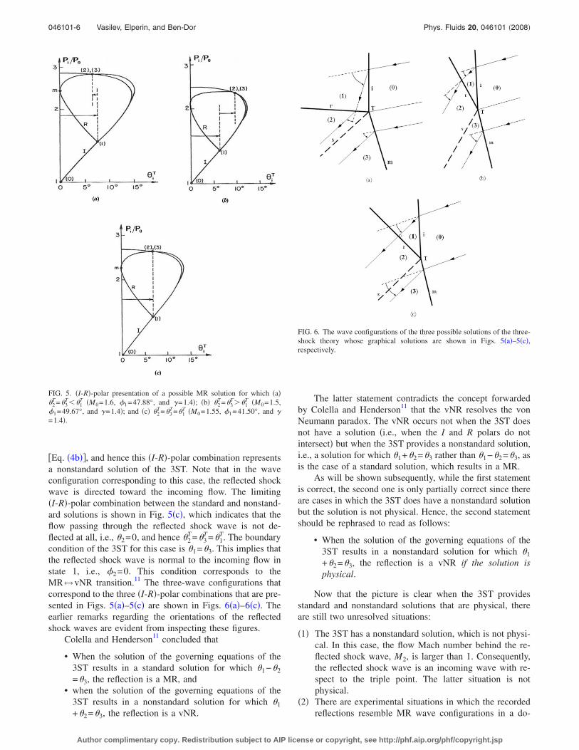
�Eq. �4b��, and hence this �I-R�-polar combination representsa nonstandard solution of the 3ST. Note that in the waveconfiguration corresponding to this case, the reflected shockwave is directed toward the incoming flow. The limiting�I-R�-polar combination between the standard and nonstand-ard solutions is shown in Fig. 5�c�, which indicates that theflow passing through the reflected shock wave is not de-flected at all, i.e., �2=0, and hence �2
T=�3T=�1
T. The boundarycondition of the 3ST for this case is �1=�3. This implies thatthe reflected shock wave is normal to the incoming flow instate 1, i.e., �2=0. This condition corresponds to theMR↔vNR transition.11 The three-wave configurations thatcorrespond to the three �I-R�-polar combinations that are pre-sented in Figs. 5�a�–5�c� are shown in Figs. 6�a�–6�c�. Theearlier remarks regarding the orientations of the reflectedshock waves are evident from inspecting these figures.
Colella and Henderson11 concluded that
• When the solution of the governing equations of the3ST results in a standard solution for which �1−�2
=�3, the reflection is a MR, and• when the solution of the governing equations of the
3ST results in a nonstandard solution for which �1
+�2=�3, the reflection is a vNR.
The latter statement contradicts the concept forwardedby Colella and Henderson11 that the vNR resolves the vonNeumann paradox. The vNR occurs not when the 3ST doesnot have a solution �i.e., when the I and R polars do notintersect� but when the 3ST provides a nonstandard solution,i.e., a solution for which �1+�2=�3 rather than �1−�2=�3, asis the case of a standard solution, which results in a MR.
As will be shown subsequently, while the first statementis correct, the second one is only partially correct since thereare cases in which the 3ST does have a nonstandard solutionbut the solution is not physical. Hence, the second statementshould be rephrased to read as follows:
• When the solution of the governing equations of the3ST results in a nonstandard solution for which �1
+�2=�3, the reflection is a vNR if the solution isphysical.
Now that the picture is clear when the 3ST providesstandard and nonstandard solutions that are physical, thereare still two unresolved situations:
�1� The 3ST has a nonstandard solution, which is not physi-cal. In this case, the flow Mach number behind the re-flected shock wave, M2, is larger than 1. Consequently,the reflected shock wave is an incoming wave with re-spect to the triple point. The latter situation is notphysical.
�2� There are experimental situations in which the recordedreflections resemble MR wave configurations in a do-
FIG. 5. �I-R�-polar presentation of a possible MR solution for which �a��2
T=�3T��1
T �M0=1.6, �1=47.88°, and �=1.4�; �b� �2T=�3
T��1T �M0=1.5,
�1=49.67°, and �=1.4�; and �c� �2T=�3
T=�1T �M0=1.55, �1=41.50°, and �
=1.4�.
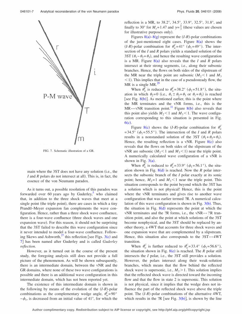
FIG. 6. The wave configurations of the three possible solutions of the three-shock theory whose graphical solutions are shown in Figs. 5�a�–5�c�,respectively.
046101-6 Vasilev, Elperin, and Ben-Dor Phys. Fluids 20, 046101 �2008�
Author complimentary copy. Redistribution subject to AIP license or copyright, see http://phf.aip.org/phf/copyright.jsp
main where the 3ST does not have any solution �i.e., theI and R polars do not intersect at all�. This is, in fact, theessence of the von Neumann paradox.
As it turns out, a possible resolution of this paradox wasforwarded over 60 years ago by Guderley,5 who claimedthat, in addition to the three shock waves that meet at asingle point �the triple point�, there are cases in which a tinyPrandtl–Meyer expansion fan complements the wave con-figuration. Hence, rather than a three shock wave confluence,there is a four-wave confluence �three shock waves and oneexpansion wave�. For this reason, it should not be surprisingthat the 3ST failed to describe this wave configuration sinceit never intended to model a four-wave confluence. Follow-ing Skews and Ashworth,27 this reflection �see Figs. 3�c� and7� has been named after Guderley and is called Guderleyreflection.
However, as it turned out in the course of the presentstudy, the foregoing analysis still does not provide a fullpicture of the phenomenon. As will be shown subsequently,there is an intermediate domain, between the vNR and theGR domains, where none of these two wave configurations ispossible and there is an additional wave configuration in thisintermediate domain, which has not been reported yet.
The existence of this intermediate domain is shown inthe following by means of the evolution of the �I-R�-polarcombinations as the complementary wedge angle, �w
C=90°−�1, is decreased from an initial value of 41°, for which the
reflection is a MR, to 38.2°, 34.5°, 33.9°, 32.5°, 31.8°, andfinally to 30° for Ms=1.47 and �= 5
3 �these values are chosenfor illustrative purposes only�.
Figures 8�a�–8�g� represent the �I-R�-polar combinationsof the just-mentioned eight cases. Figure 8�a� shows the�I-R�-polar combination for �w
C=41° ��1=49° �. The inter-section of the I and R polars yields a standard solution of the3ST ��1−�2=�3�, and hence the resulting wave configurationis a MR. Figure 8�a� also reveals that the I and R polarsintersect at their strong segments, i.e., along their subsonicbranches. Hence, the flows on both sides of the slipstream ofthe MR near the triple point are subsonic �M2�1 and M3
�1�. This implies that in the case of a pseudosteady flow, theMR is a single MR.29
When �wC is reduced to �w
C=38.2° ��1=51.8° �, the situ-ation in which �2=0 �i.e., �1��2=�3 or �1=�3� is reached�see Fig. 8�b��. As mentioned earlier, this is the point wherethe MR terminates and the vNR forms, i.e., this is theMR↔vNR transition point.11 Figure 8�b� also reveals thatthis point also yields M2�1 and M3�1. The wave configu-ration corresponding to this situation is presented in Fig.6�c�.
Figure 8�c� shows the �I-R�-polar combination for �wC
=34.5° ��1=55.5° �. The intersection of the I and R polarsresults in a nonstandard solution of the 3ST ��1+�2=�3�.Hence, the resulting reflection is a vNR. Figure 8�c� alsoreveals that the flows on both sides of the slipstream of thevNR are subsonic �M2�1 and M3�1� near the triple point.A numerically calculated wave configuration of a vNR isshown in Fig. 3�a�.
When �wC is reduced to �w
C=33.9° ��1=56.1° �, the situ-ation shown in Fig. 8�d� is reached. Now the R polar inter-sects the subsonic branch of the I polar exactly at its sonicpoint; hence, M2=1 and M3�1 near the triple point. Thissituation corresponds to the point beyond which the 3ST hasa solution which is not physical! Hence, this is the pointwhere the vNR terminates and gives rise to another waveconfiguration that was earlier termed ?R. A numerical calcu-lation of this wave configuration is shown in Fig. 3�b�. Thus,the situation in Fig. 8�d� represents the point at which thevNR terminates and the ?R forms, i.e., the vNR↔ ?R tran-sition point, and also the point at which solutions of the 3STbecome nonphysical, and the 3ST should be replaced by an-other theory, a 4WT that accounts for three shock waves andone expansion wave that are complemented by a slipstream.Hence, this situation also corresponds to the 3ST↔4WTtransition.
When �wC is further reduced to �w
C=33.4° ��1=56.6° �,the situation shown in Fig. 8�e� is reached. The R polar stillintersects the I polar, i.e., the 3ST still provides a solution.However, the polars intersect along their weak-solutionbranches, which means that the flow behind the reflectedshock wave is supersonic, i.e., M2�1. This solution impliesthat the reflected shock wave is directed toward the incomingflow and that the flow in state 2 is supersonic. This solutionis not physical, since it implies that the wedge does not in-fluence the part of the reflected shock wave above the triplepoint. The �I-R�-polar combinations of the alternative 4WT,which results in the ?R �see Fig. 3�b��, is shown by the line
FIG. 7. Schematic illustration of a GR.
046101-7 Analytical reconsideration of the von Neumann paradox Phys. Fluids 20, 046101 �2008�
Author complimentary copy. Redistribution subject to AIP license or copyright, see http://phf.aip.org/phf/copyright.jsp
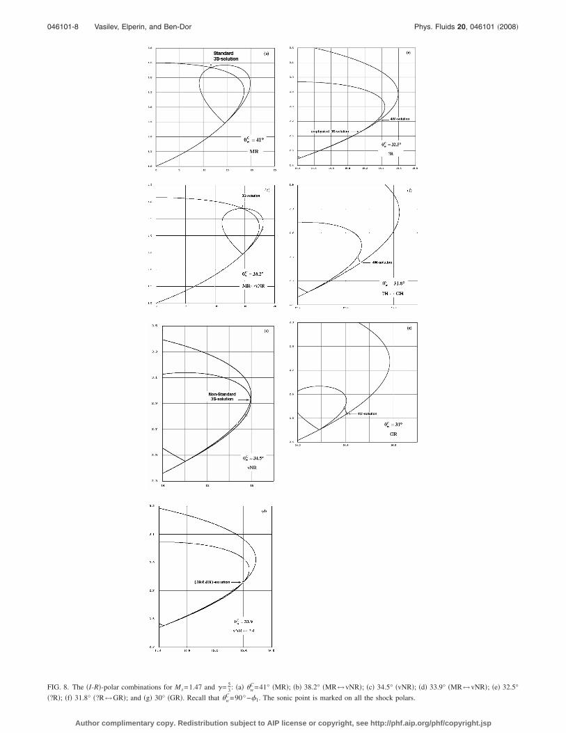
FIG. 8. The �I-R�-polar combinations for Ms=1.47 and �= 53 : �a� �w
C=41° �MR�; �b� 38.2° �MR↔vNR�; �c� 34.5° �vNR�; �d� 33.9° �MR↔vNR�; �e� 32.5°
�?R�; �f� 31.8° �?R↔GR�; and �g� 30° �GR�. Recall that �wC=90°−�1. The sonic point is marked on all the shock polars.
046101-8 Vasilev, Elperin, and Ben-Dor Phys. Fluids 20, 046101 �2008�
Author complimentary copy. Redistribution subject to AIP license or copyright, see http://phf.aip.org/phf/copyright.jsp

bridging a subsonic state on the I polar �state 3� with thesonic point of the R polar �state 2�. The fact that a Prandtl–Meyer expansion fan exists between two flow zones whichare not supersonic can be explained as follows. A Prandtl–Meyer expansion fan cannot exist in a homogeneous sub-sonic flow. However, in the case under consideration, there isa strongly inhomogeneous converging flow ahead of the fan,and therefore the Prandtl–Meyer expansion fan can exist. Ifwe consider two adjacent stream lines, the flow betweenthem is similar to the flow inside the Laval nozzle with theminimum cross section at the boundary of the expansion fan.
When �wC is reduced to �w
C=31.8° ��1=58.2° �, the situ-ation shown in Fig. 8�f� is reached. Now the I and R polarsdo not intersect at all, and the 3ST does not provide anysolution. Based on the 4WT,23 which was presented earlier,the sonic points of the I and the R polars are bridged; hence,M2=1 and M3=1 near the triple point. In fact, this is thepoint where the ?R terminates and the modified GR forms,i.e., the ?R↔GR transition point. Note that at this point, theR polar is tangent to the I polar at its origin.
It should be noted here that the Mach numbers in TableI, in the cases of ?R and GR, are near the triple point. As canbe seen in Figs. 3�b� and 3�c�, as the flows move away fromthe triple point, their Mach numbers change. In the cases of?R and GR, the flow after the reflected shock wave changesfrom sonic to supersonic at transition, and in the case of aGR, the flow behind the Mach stem changes from supersonicto sonic. The sonic line is thus adjacent to the reflected shockand the flow does not need to accelerate to sonic conditionsthrough a subsonic region. Thus, the transition boundariesdetermined should be accurate. For conditions away from thetransition boundaries, however, account will need to be takenof the converging subsonic flow behind the reflected shock,as shown in Fig. 3.
A further reduction of �wC to �w
C=31° ��1=59° � results inthe situation shown in Fig. 8�g�. The I and R polars do notintersect, and the 3ST does not provide any solution. Basedon the 4WT,23 which was presented earlier, the I and the Rpolars are bridged at M2=1 and M3�1. The numericallyobtained wave configuration of a modified GR is shown in
Fig. 3�c� and sketched schematically in Fig. 4. A Prandtl–Meyer expansion fan bridges the flows in states 2 and 3whose conditions are sufficient to support a Prandtl–Meyerexpansion fan.
The above-presented evolution of the types of reflectionthat are encountered when �w
C is reduced for Ms=1.47 and�= 5
3 and the transition criteria between them are summarizedin Table I. It should be noted here that Henderson30 hadcalculated some of these transition lines while mathemati-cally investigating possible solutions of the 3ST. However,neither he nor anyone else attributed physical importance tothese mathematical boundaries. In the present study, we sug-gest a full picture of the reflection phenomenon in thenonstandard-3ST domain and beyond it. The flow patternsdescribed in the present study are consistent with all theavailable numerical and experimental data. The transitioncriteria of Table I are shown in Fig. 9 in an evolution-tree-type presentation.
Based on the foregoing discussion, Figs. 10�a� and 10�b�show the domains of and the transition boundaries betweenthe various shock wave reflection configurations in the�Ms ,�w
C� plane for �a� a diatomic ��= 75
� and �b� a monatomic��= 5
3� gas, respectively. Curve 1 is the MR↔vNR transition
curve, i.e., �2=90° on this curve. Above this curve, �2
�90° and the reflection is a MR. Curve 2 is the vNR↔?Rtransition curve, i.e., M2=1 on this curve. It should be notedhere that this curve is different from the M2=1 on the leftbranch of the R polar, which is the sonic criterion for theRR↔ IR transition. This curve also separates between thedomains in which the 3ST does or does not have physicalsolutions, i.e., it corresponds to the 3ST↔4WT transition.Curve 3 is the ?R↔GR transition curve, i.e., M3=1 on thiscurve. Curve 4 is the curve M1=1. Below this curve, the flowbehind the incident shock wave is subsonic and no reflectioncan take place. The domain below this curve is sometimesreferred to as the no-reflection domain �NR domain�. The NRdomain exists only in the �Ms ,�w
C� plane. It vanishes in themore physical �Ms ,�w� plane �recall that �w
C=�w+ where is the triple-point trajectory angle�. Curve 5 divides the�Ms ,�w
C� plane into two domains: Above it, the 3ST has atleast one solution �not necessarily physical� and below it, the
TABLE I. Summary of the reflection types that occur when �wC is decreased
for Ms=1.47 and �= 53 .
�wC and �1
Mach numberin state 2
near the triplepoint
Mach numberin state 3
near the triplepoint
Reflectionconfigurationand transition
criteria
�wC=41.0° and �1=49.0° M2�1 M3�1 MR
�wC=38.2° and �1=51.8° �2=90° MR↔vNR
�wC=34.5° and �1=55.5° M2�1 M3�1 vNR
�wC=33.9° and �1=56.1° M2=1 vNR↔ ?R
also3ST↔4WT
�wC=33.4° and �1=56.6° M2=1 M3�1 ?R
�wC=31.8° and �1=58.2° M3=1 ?R↔GR
�wC=31.0° and �1=59.0° M2=1 M3�1 GR
FIG. 9. Evolution-tree-type presentation of the transition criteria betweenthe various reflections.
046101-9 Analytical reconsideration of the von Neumann paradox Phys. Fluids 20, 046101 �2008�
Author complimentary copy. Redistribution subject to AIP license or copyright, see http://phf.aip.org/phf/copyright.jsp

3ST does not have any solution. Consequently, betweencurves 2 and 5, the 3ST has a solution, which is not physical.The von Neumann paradox existed inside the domainbounded by curves 2 and 4. Guderley5 resolved the paradoxin the domain bounded by curves 3 and 4 by forwarding thefour-wave concept �three shock waves and one expansion
wave�. The reflection in this domain is a GR �see Fig. 3�c��.The reflection that occurs inside the domain bounded bycurves 2 and 3 is ?R and is shown in Fig. 3�b�. To the best ofour knowledge, this wave configuration was not consideredpreviously. In summary, the MR domain is above curve 1,the vNR domain is located between curves 1 and 2, the ?R
FIG. 10. Domains of and the transitionboundaries between the various shockwave reflection configurations in the�Mi ,�w
C� plane for �a� �= 75 and �b� �
= 53 . Curve 1: The MR↔vNR transi-
tion curve, i.e., �2=90°. Curve 2: ThevNR↔ ?R transition curve, i.e., M2
=1. This curve also separates the do-mains in which the 3ST does or doesnot have a physical solution. Curve 3:The ?R↔GR transition curve, i.e.,M3=1. Curve 4: The curve on whichM1=1. Below this curve, the flow be-hind the incident shock wave is sub-sonic and a reflection cannot takeplace! Curve 5: Above this curve, the3ST has at least one mathematical so-lution �not necessarily physical� andbelow it, the 3ST does not have anymathematical solution ��w
C=�w+= /2−�1, Mi=M0 sin �1, Mi is theincident shock wave Mach number, �w
is the reflecting wedge angle, and isthe triple-point trajectory angle�.
046101-10 Vasilev, Elperin, and Ben-Dor Phys. Fluids 20, 046101 �2008�
Author complimentary copy. Redistribution subject to AIP license or copyright, see http://phf.aip.org/phf/copyright.jsp

domain is located between curves 2 and 3, the modified GRdomain is located between curves 3 and 4, and the NR do-main is below curve 4. The 3ST has at least one solution �notnecessarily physical� in the domain above curve 5 and nosolutions in the domain below curve 5. Chapman31 who fol-lowed Henderson’s30 mathematical investigation drew curves1, 2, and 4 �see Fig. 11.2.3a in his book� in the �M0 ,�1�domain without giving them their physical importance andinterpretation as has been done in the present study.
SUMMARY
The reflection of weak shock waves has been reconsid-ered analytically using shock polars and all possible flowpatterns were analyzed.
It has been pointed out that the vNR concept that wasforwarded by Colella and Henderson11 as a resolution of thevon Neumann paradox is not correct, since even according tothem, the vNR occurs at conditions for which the 3ST doeshave a solution.
Based on the boundary condition across the slipstream ofa three-shock confluence, the solutions of the 3ST were clas-sified as “standard-3ST solutions” and “nonstandard-3ST so-lutions.” When the 3ST has a standard solution, the reflectionis a MR.
It was shown that there are two situations in the non-standard case:
• A situation where the 3ST has solutions of which atleast one is physical. The wave configuration in thiscase is a vNR.
• A situation where the 3ST has a solution, which is notphysical, and hence no reflection having a three-shockconfluence is possible. A new wave configuration, ?R,occurs in this case.
In addition, it was shown that there are cases when the3ST does not have any solution. The wave configuration inthis case is a modified GR. It should be noted here thatalthough we use the term Guderley reflection, the wave con-figuration that was originally suggested by Guderley5,6 didnot include a slipstream �see Fig. 7�, while the present nu-merical investigation revealed a wave configuration that in-cludes a slipstream �see Fig. 4�.
In the cases where the 3ST does not provide a physicalor any solution, it is replaced by a 4WT, which was alsopresented in this study.
Both the ?R and the modified GR include a Prandtl–Meyer expansion fan in addition to the well known threeshock waves of a MR. ?R and the GR differ in the number oftheir supersonic patches. Numerically obtained wave con-
figurations of vNR, a ?R, and a modified GR are shown inFigs. 3�a�–3�c�, respectively. Note that while the GR wassuggested by Guderley5 and modified in this study in order toresolve the von Neumann paradox, the ?R was first sug-gested by Vasilev.23
Finally, the domains and transition boundaries betweenthe four types of reflection that can take place in the weakshock domain, MR, vNR, ?R, and GR, were elucidated.
For the reader’s convenience, formulas for calculatingthe transition lines between MR, vNR, ?R, and modified GRthat are shown in Fig. 10 are presented in the Appendix.
ACKNOWLEDGMENTS
This study was conducted under the auspices of the Dr.Morton and Toby Mower Chair of Shock Wave Studies.
APPENDIX: FORMULAS FOR THE TRANSITIONBOUNDARIES
Using the expression for the Mach number, M=u /��RT, where �=CP /CV is the specific heat capacity ratioand R is the specific gas constant, the eight parameters ofEqs. �1a�–�1d� become pi, pj, Ti, Tj, Mi, Mj, � j, and � j.Assuming that pi, Ti, Mi, and � j are known results in thefollowing solution of the conservation equations across anoblique shock wave:
pj
pi= 1 +
2�
� + 1�Mi
2 sin2 � j − 1� , �A1a�
� j
�i=
� + 1
�� − 1� +2
Mi2 sin2 � j
, �A1b�
Mj2 =
�1 + 12 �� − 1�Mi
2 sin2 � j�2 + � 14 �� + 1�Mi
2 sin 2� j�2
�1 + 12 �� − 1�Mi
2 sin2 � j���Mi2 sin2 � j − 1
2 �� − 1�� ,
�A1c�
� j = tan−1 �Mi2 sin2 � j − 1�cot � j
1 + Mi2� 1
2 �� + 1� − sin2 � j�. �A1d�
Shock polars
Equations �A1a� and �A1d� provide the �p ,�� polar for asupersonic flow with Mach number Mi in a parametric form.The full shock polar can be obtained by changing the param-eter � j in the range sin−1�1 /Mi��� j �−sin−1�1 /Mi�. Theexpression for the slope of the �p ,�� polar, dp /d�= �dp /d�� / �d� /d��, reads
1
pi
dpj
d� j=� 2�
�� + 1���Mi sin � j�4 − ��� − 1� +1
4�� + 1�Mi
2�Mi sin � j�2 − 1�Mi2 sin 2� j
��Mi sin � j�4 + 2�1 − 14 �� + 1�Mi
2��Mi sin � j�2 − �1 + 12 �� + 1�Mi
2� . �A2�
046101-11 Analytical reconsideration of the von Neumann paradox Phys. Fluids 20, 046101 �2008�
Author complimentary copy. Redistribution subject to AIP license or copyright, see http://phf.aip.org/phf/copyright.jsp

Solution of the three-shock theory
For the incident shock wave �j=1 and i=0, see Fig. 2�,Eqs. �A1a�, �A1c�, and �A1d� read
p1
p0= 1 +
2�
� + 1�M0
2 sin2 �1 − 1� , �A3a�
�1 = tan−1 �M02 sin2 �1 − 1�cot �1
1 + M02� 1
2 �� + 1� − sin2 �1�, �A3b�
M12 =
�1 + 12 �� − 1�M0
2 sin2 �1�2 + � 14 �� + 1�M0
2 sin 2�1�2
�1 + 12 �� − 1�M0
2 sin2 �1���M02 sin2 �1 − 1
2 �� − 1�� .
�A3c�
For the reflected shock wave �j=2 and i=1�, Eqs. �A1a�,�A1c�, and �A1d� yield
p2
p1= 1 +
2�
� + 1�M1
2 sin2 �2 − 1� , �A4a�
�2 = tan−1 �M12 sin2 �2 − 1�cot �2
1 + M12� 1
2 �� + 1� − sin2 �2�, �A4b�
M22 =
�1 + 12 �� − 1�M1
2 sin2 �2�2 + � 14 �� + 1�M1
2 sin 2�2�2
�1 + 12 �� − 1�M1
2 sin2 �2���M12 sin2 �2 − 1
2 �� − 1���A4c�
Similarly, for the Mach stem �j=3 and i=0�, one obtains
p3
p0= 1 +
2�
� + 1�M0
2 sin2 �3 − 1� , �A5a�
�3 = tan−1 �M02 sin2 �3 − 1�cot �3
1 + M02� 1
2 �� + 1� − sin2 �3�, �A5b�
M32 =
�1 + 12 �� − 1�M0
2 sin2 �3�2 + � 14 �� + 1�M0
2 sin 2�3�2
�1 + 12 �� − 1�M0
2 sin2 �3���M02 sin2 �3 − 1
2 �� − 1�� .
�A5c�
The pressure boundary condition across the slipstream �p2
= p3� can be rewritten as follows:
p3
p0=
p2
p1
p1
p0. �A6�
Inserting Eqs. �A3a�, �A4a�, and �A5a� into Eq. �A6� yieldsthe following formula:
sin2 �3 =��2 − 1� + �2�M0
2 sin2 �1 − �� − 1���2�M12 sin2 �2 − �� − 1��
2��� + 1�M02 . �A7�
Inserting relations �A3b�, �A4b�, �A5b�, �A3c�, �A4c�, and �A7� into the second boundary condition at the slipstream,�1��2=�3 �Eq. �3�� results in a single implicit equation for �2 as a function of M0 and �1.
Equations for calculating the transition lines in Fig. 10
In the following, closed sets of equations, which are all based on the above equations, for calculating the various transitionlines in Fig. 10 are given.
Line 1: The MR^vNR transition
On this line, �2= /2, i.e., sin �2=1 and �2=0. Hence, the flow-deflection boundary condition reduces to
�1 = �3 �A8�
Inserting sin �2=1 into Eq. �A7� yields
sin2 �3 =��2 − 1� + �2�M0
2 sin2 �1 − �� − 1���2�M12 − �� − 1��
2��� + 1�M02 . �A9�
Inserting M1=M1�M0 ,�1� from Eq. �A3c� into Eq. �A9� yields
�3 = �3�M0,�1� .
Inserting this relation into Eq. �A5b� yields the following relation:
046101-12 Vasilev, Elperin, and Ben-Dor Phys. Fluids 20, 046101 �2008�
Author complimentary copy. Redistribution subject to AIP license or copyright, see http://phf.aip.org/phf/copyright.jsp

�3 = �3�M0,�1� . �A10�
Inserting the latter relation into Eq. �A8� together with Eq.�A3b�, one obtains the formula for the MR↔vNR transitionline �line 1 in Fig. 10�:
�3�M0,�1� = �2�M0,�1� . �A11�
Line 2: The vNR^ ?R transition
On this line, M2=1. Inserting M1�M0 ,�1� from Eq.�A3c� into Eq. �A4c� and applying the condition M2=1 re-sults in the following relation:
�2 = �2�M0,�1� .
Inserting the latter relation together with M1�M0 ,�1� fromEq. �A3c� into Eqs. �A4b� and �A7� yields the followingformulas:
�3 = �3�M0,�1� ,
�A12��2 = �2�M0,�1� ,
Inserting �3=�3�M0 ,�1� into Eq. �A5b� yields the followingrelation:
�3 = �3�M0,�1� . �A13�
Inserting Eqs. �A3b�, �A12�, and �A13� into the flow-deflection boundary condition of a nonstandard solution re-
sults in the formula for the vNR↔ ?R transition line �line 2in Fig. 10�:
�3�M0,�1� = �1�M0,�1� + �2�M0,�1� . �A14�
Line 3: The ?R^GR transition
Equations �1� and �5�–�8� imply the dependence M3
=M3�M0 ,�1�. The equation of line 3 for the ?R↔GR tran-sition is M3=1.
Line 5: The 3ST^4WT transition
In this case, the R polar is tangent to the I polar at thetransition. Hence, the slopes of the R and the I polars areidentical at the point where the R polar emanates from the Ipolar. This condition implies that
�dpI
d��
1= �dpR
d��
1,
where the subscripts I and R refer to the I and R polars,respectively, and 1 indicates the point on the I polar fromwhich the R polar emanates. The slope of a general �p ,��polar is given by Eq. �A2�. Applying this equation to the Ipolar results in the following formula:
� 1
p0
dpI
d��
1=� 2�
�� + 1���M0 sin �1�4 − ��� − 1� +1
4�� + 1�2M0
2�M0 sin �1�2 − 1�M02 sin 2�1
��M0 sin �1�4 + 2�1 − 14 �� + 1�M0
2��M0 sin �1�2 − �1 + 12 �� + 1�M0
2� . �A15�
Similarly, applying Eq. �A2� to the R polar yields
� 1
p1
dpR
d��
1=� 2�
�� + 1���M1 sin �2�4 − ��� − 1� +1
4�� + 1�2M1
2�M1 sin �2�2 − 1�M12 sin 2�2
��M1 sin �2�4 + 2�1 − 14 �� + 1�M1
2��M1 sin �2�2 − �1 + 12 �� + 1�M1
2� . �A16a�
Multiplying Eq. �A16a� by Eq. �A3a�, one obtains
� 1
p0
dpR
d��
1= �1 +
2�
� + 1�M0
2 sin2 �1 − 1��
� 2�
�� + 1���M1 sin �2�4 − ��� − 1� +1
4�� + 1�2M1
2�M1 sin �2�2 − 1�M12 sin 2�2
��M1 sin �2�4 + 2�1 − 14 �� + 1�M1
2��M1 sin �2�2 − �1 + 12 �� + 1�M1
2� . �A16b�
The slope on the R polar is measured at its origin; hence, at that point, M1 sin �2=1. Inserting this value into Eq. �A16b� yields
� 1
p0
dpR
d��
1= �1 +
2�
� + 1�M0
2 sin2 �1 − 1��2�
�� + 1�� − ��� − 1� +1
4�� + 1�2M1
2 − 1�2�M12 − 1�1/2
� + 2�1 − 14 �� + 1�M1
2� − �1 + 12 �� + 1�M1
2� . �A16c�
Using Eq. �A3c�, the right hand side of Eq. �A16c� can be expressed as a function of M0 and �1 only. Equating the slopesgiven by Eqs. �A15� and �A16c� results in the formula for the 3ST↔4WT transition line �line 5 in Fig. 10�.
046101-13 Analytical reconsideration of the von Neumann paradox Phys. Fluids 20, 046101 �2008�
Author complimentary copy. Redistribution subject to AIP license or copyright, see http://phf.aip.org/phf/copyright.jsp

Line 4: The GR^no-reflection transition
The relation for line 4 below for which the flow behind the incident shock wave is subsonic, and hence no reflection cantake place, is as follows:31
sin2 �1 =12 �� − 3� + 1
2 �� + 1�M02 + �� + 1�1/2� 1
4 �� + 9� + 12 �� − 3�M0
2 + 14 �� + 1�M0
4�1/2
2�M02 . �A17�
1E. Mach, “Uber den verlauf von funkenwellen in der ebene und imraume,” Vienna Acad. Sitzungsberichte 78, 819 �1878�.
2J. von Neumann, “Oblique reflection of shocks,” in John von Neumann:Collected Works, 1903–1957, 6 Vols., edited by A. H. Taub �Pergamon,Oxford, UK, 1961–1963�, Vol. VI, pp. 238–299.
3J. von Neumann, “Refraction, intersection and reflection of shock waves,”in John von Neumann: Collected Works, 1903–1957, 6 Vols., edited by A.H. Taub �Pergamon, Oxford, UK, 1961–1963�, Vol. VI, pp. 300–308.
4W. Bleakney and A. H. Taub, “Interaction of shock waves,” Rev. Mod.Phys. 21, 584 �1949�.
5K. G. Guderley, “Considerations on the structure of mixed subsonic-supersonic flow patterns,” Air Materiel Command Technical Report No.F-TR-2168-ND, ATI No. 22780, GS-AAF-Wright Field No. 39, U.S.Wright–Patterson Air Force Base, Dayton, OH �October 1947�.
6K. G. Guderley, Theorie Schallnaher Strömungen �Springer-Verlag, Ber-lin, 1957�.
7D. R. White, “An experimental survey of the Mach reflection of shockwaves,” Department of Physics, Princeton University Technical ReportNo. II-10 �1951�.
8D. R. White, “An experimental survey of the Mach reflection of shockwaves,” Ph.D. thesis, Princeton University; see also Proceedings of theSecond Midwestern Conference on Fluid Mechanics, Ohio State Univer-sity, 1952, Vol. 3, p. 253.
9B. I. Zaslavsky and P. A. Safarov, “Mach reflection of weak shock wavesfrom a rigid wall,” J. Appl. Mech. Tech. Phys. 14, 624 �1973�.
10L. F. Henderson and A. Siegenthaler, “Experiments on the diffraction ofweak blast waves: The von Neumann paradox,” Proc. R. Soc. London, Ser.A 369, 537 �1980�.
11P. Colella and L. F. Henderson, “The von Neumann paradox for the dif-fraction of weak shock waves,” J. Fluid Mech. 213, 71 �1990�.
12M. Olim and J. M. Dewey, “A revised three-shock solution for the Machreflection of weak shocks,” Shock Waves 2, 167 �1992�.
13A. Sasoh and K. Takayama, “Characterization of disturbance propagationin weak shock-wave reflections,” J. Fluid Mech. 277, 331 �1994�.
14J. Sternberg, “Triple-shock-wave intersections,” Phys. Fluids 2, 179�1959�.
15G. Birkhoff, Hydrodynamics: A Study in Logic, Fact, and Similitude, 2nded. �Princeton University Press, Princeton, 1960�.
16B. W. Skews, “The flow in the vicinity of the three shock intersection,”
CASI Trans. 4, 99 �1972�.17V. G. Dulov, “Motion of a triple configuration of shock waves with for-
mation of wake behind branching point,” J. Appl. Mech. Tech. Phys. 14,791 �1973�.
18T. Adachi, T. Suzuki, and S. Kobayashi, “Mach reflection of a weak shockwaves,” Trans. Jpn. Soc. Mech. Eng., Ser. B 60, 2281 �1994�.
19G. P. Shindyapin, “Mach reflection and interaction of weak shock wavesunder the von Neumann paradox,” Fluid Dyn. 31, 318 �1996�.
20E. I. Vasilev, “Generalization of the von Neumann theory for the Machreflection of weak shock waves,” Vestnik Volgogradskogo Gosu-darstvenogo Universiteta. Seria 1. Fizika I Mathematika 3, 74 �1998�.
21E. I. Vasilev, ”High-resolution simulation for the Mach reflection of weakshock waves,” in Proceedings of the Fourth European ComputationalFluid Dynamics Conference (ECCOMAS CFD 1998, Athens, Greece), ed-ited by K. D. Papailiou, D. Tsahalis, J. Periaux, Ch. Hirsch, and M. Pan-dolfi �John Wiley and Sons, Chichester, 1998�, Vol. 1, Part 1, pp. 520–527.
22E. I. Vasilev and A. N. Kraiko, “Numerical simulation of weak shockdiffraction over a wedge under the von Neumann paradox conditions,”USSR Comput. Math. Math. Phys. 39, 1335 �1999�.
23E. I. Vasilev, “Four-wave scheme of weak Mach shock wave interactionunder von Neumann paradox conditions,” Fluid Dyn. 34, 421 �1999�.
24A. M. Tesdall and J. K. Hunter, “Self-similar solutions for weak shockreflection,” SIAM J. Appl. Math. 63, 42 �2002�.
25A. M. Tesdall, R. Sanders, and B. L. Keyfitz, “The triple point paradox forthe nonlinear wave system,” SIAM J. Appl. Math. 67, 321 �2006�.
26L. F. Henderson, E. I. Vasilev, G. Ben-Dor, and T. Elperin, “The wall-jetting effect in Mach reflection: Theoretical consideration and numericalinvestigation,” J. Fluid Mech. 479, 259 �2003�.
27B. W. Skews and J. T. Ashworth, “The physical nature of weak shockwave reflection,” J. Fluid Mech. 542, 105 �2005�.
28R. Kawamura and H. Saito, “Reflection of shock waves—1. Pseudo-stationary case,” J. Phys. Soc. Jpn. 11, 584 �1956�.
29G. Ben-Dor, Shock Wave Reflection Phenomena �Springer, New York,2007�.
30L. F. Henderson, “The three shock confluence on a simple wedge intake,”Aeronaut. Q. 16, 42 �1965�.
31C. J. Chapman, High Speed Flow �Cambridge University Press, Cam-bridge, 2000�.
046101-14 Vasilev, Elperin, and Ben-Dor Phys. Fluids 20, 046101 �2008�
Author complimentary copy. Redistribution subject to AIP license or copyright, see http://phf.aip.org/phf/copyright.jsp