analytical modeling of open-circuit air-gap field...
TRANSCRIPT
This is a repository copy of Analytical modeling of open-Circuit air-Gap field distributions inmultisegment and multilayer interior permanent-magnet machines.
White Rose Research Online URL for this paper:http://eprints.whiterose.ac.uk/9076/
Article:
Zhu, L., Jiang, S.Z., Zhu, Z.Q. et al. (1 more author) (2009) Analytical modeling of open-Circuit air-Gap field distributions in multisegment and multilayer interior permanent-magnet machines. IEEE Transactions on Magnetics, 45 (8). pp. 3121-3130. ISSN 0018-9464
https://doi.org/10.1109/TMAG.2009.2019841
[email protected]://eprints.whiterose.ac.uk/
Reuse
Unless indicated otherwise, fulltext items are protected by copyright with all rights reserved. The copyright exception in section 29 of the Copyright, Designs and Patents Act 1988 allows the making of a single copy solely for the purpose of non-commercial research or private study within the limits of fair dealing. The publisher or other rights-holder may allow further reproduction and re-use of this version - refer to the White Rose Research Online record for this item. Where records identify the publisher as the copyright holder, users can verify any specific terms of use on the publisher’s website.
Takedown
If you consider content in White Rose Research Online to be in breach of UK law, please notify us by emailing [email protected] including the URL of the record and the reason for the withdrawal request.
IEEE TRANSACTIONS ON MAGNETICS, VOL. 45, NO. 8, AUGUST 2009 3121
Analytical Modeling of Open-Circuit Air-Gap Field Distributions in
Multisegment and Multilayer Interior Permanent-Magnet Machines
Li Zhu�, S. Z. Jiang�, Z. Q. Zhu�, Fellow, IEEE, and C. C. Chan�, Fellow, IEEE
Department of Electrical Engineering, Shanghai Jiao Tong University, Shanghai, China
Department of Electronic and Electrical Engineering,University of Sheffield, Sheffield S1 3JD, U.K.
Department of Electrical and Electronic Engineering, University of Hong Kong, Hong Kong
We present a simple lumped magnetic circuit model for interior permanent-magnet (IPM) machines with multisegment and multilayerpermanent magnets. We derived analytically the open-circuit air-gap field distribution, average air-gap flux density, and leakage fluxes.To verify the developed models and analytical method, we adopted finite-element analysis (FEA). We show that for prototype machines,the errors between the FEA and analytically predicted results are 1% for multisegment IPM machines and 2% for multilayer IPMmachines. By utilizing the developed lumped magnetic circuit models, the IPM machines can be optimized for maximum fundamentaland minimum total harmonic distortion of the air-gap flux density distribution.
Index Terms—Air-gap flux density, interior permanent magnet, leakage flux, multilayer, multisegment.
I. INTRODUCTION
DUE to high efficiency, high power density, high powerfactor, and high torque density, together with the devel-
opment of permanent-magnet (PM) material and power elec-tronics, PM brushless machines are increasingly being used invarious applications, such as variable-speed drives, servo drives,electric vehicles, and other industrial drives [1], [2]. Comparedwith surface-mounted PM (SPM) machines, interior permanent-magnet (IPM) synchronous machines have robust rotor con-struction, high reluctance torque, and high irreversible demag-netization withstand, and are eminently suitable for electric ve-hicles which require a wide constant power operating speedrange.
However, due to significant leakage flux and magnetic satu-ration in IPM machines, it is very difficult to directly employanalytical methods to predict the open-circuit air-gap field dis-tribution. Although the finite-element analysis (FEA) can pre-cisely obtain the flux density distribution, it is time consumingand still often used only for design verification. Therefore, alumped magnetic circuit model usually is a good compromisebetween simplicity and accuracy [3]–[9]. By way of examples,Laplacian or quasi-Poissonian field equations were directlysolved analytically for SPM machines [10], [11] and inset PMmachines [12], conformal mapping techniques were used foranalyzing the influence of stator slotting [13]–[15] and rotorsaliency in IPM machines [16], [17], while lumped magneticcircuit methods [3]–[9], [18]–[26] were extensively used forSPM machines [18]–[20], switched reluctance machines [21],linear brushless dc machines [22], hybrid stepping motors [5],salient-pole synchronous machines [23], flux-switching PMmachines [24]–[26], inset PM machines [6], IPM machines [3],[4], [7]–[9], etc. In the lumped magnetic circuit analysis, the
Manuscript received December 08, 2008; revised March 14, 2009. Currentversion published July 22, 2009. Corresponding author: Z. Q. Zhu (e-mail: [email protected]).
Color versions of one or more of the figures in this paper are available onlineat http://ieeexplore.ieee.org.
Digital Object Identifier 10.1109/TMAG.2009.2019841
permeances of stator yoke and rotor yoke were often omittedfor simplicity [5]–[7], [9], [18], [22], [25], [26], or handled withthe nonlinear B-H curve of iron by iterative process for higheraccuracy [3], [4], [8], [19]–[21], [23], [24]. However, sincethere is no significant magnetic saturation at yokes, neglectingthe permeances of stator yoke and rotor yoke is usually accept-able and the results will still have fair accuracy [27]. To accountfor the slotting effect, [3], [6], [7] introduced Carter coefficientfor predicting the average air-gap flux density, and [4], [5],[18], [20], [21], [24]–[26] analytically approximated the fluxdistributions in the slots by assuming straight and semicircularlines for predicting air-gap flux density distribution. However,the stator slots can be neglected if only the average air-gapflux density is considered [8], [9], [19], [23]. To investigate theend effect, a 3-D lumped magnetic circuit was employed in[20], [24], [25]. Furthermore, lumped magnetic circuits werealso developed according to different rotor positions in order toaccount for rotor rotation [4], [5], [20], [21], [24], [26], muchattention being paid to the nonlinear permeances in teeth [20]or pole tips [21], [24], [26] by employing iterative process[20], [21], [24] or by using saturated coefficients based on FEA[26]. Lumped magnetic circuits are particularly useful for IPMmachines due to highly saturated rotor bridges and complicatedrotor configurations. The rotor bridges could be modeled asconstant flux leakage sources with preset values [6]–[8] ornonlinear permeance elements using iterative process [3], [4],[9]. Although the assumption in [6]–[8] might cause errorsince the saturation level of rotor iron bridge could be variedunder different loading conditions, it was fairly acceptable forapproximation as it resulted in significant simplification.
Hence, this paper presents improved lumped magnetic circuitmodels for analytically predicting the open-circuit air-gap fluxdensity distributions in IPM machines with multisegment andmultilayer permanent magnets. Based on the analysis of fluxlines obtained by FEA, simplified lumped magnetic circuits areobtained and Kirchhoff’s law is adopted for deriving the analyt-ical expressions of the leakage fluxes. The influence of designparameters on the average air-gap flux density is investigated.The relationship between the lumped magnetic circuit models ofdifferent number of permanent-magnet layers is discussed. Fur-thermore, by utilizing the lumped magnetic circuit models, the
0018-9464/$26.00 © 2009 IEEE
Authorized licensed use limited to: Sheffield University. Downloaded on August 10, 2009 at 09:24 from IEEE Xplore. Restrictions apply.
3122 IEEE TRANSACTIONS ON MAGNETICS, VOL. 45, NO. 8, AUGUST 2009
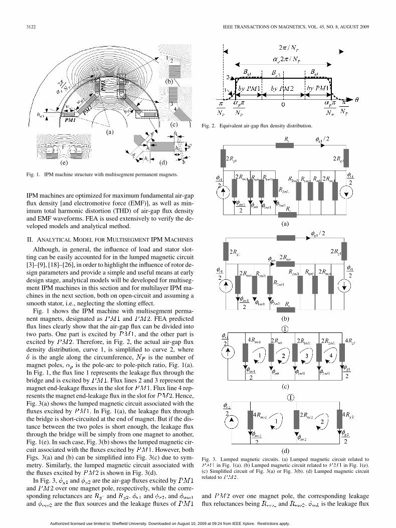
Fig. 1. IPM machine structure with multisegment permanent magnets.
IPM machines are optimized for maximum fundamental air-gapflux density [and electromotive force (EMF)], as well as min-imum total harmonic distortion (THD) of air-gap flux densityand EMF waveforms. FEA is used extensively to verify the de-veloped models and analytical method.
II. ANALYTICAL MODEL FOR MULTISEGMENT IPM MACHINES
Although, in general, the influence of load and stator slot-ting can be easily accounted for in the lumped magnetic circuit[3]–[9], [18]–[26], in order to highlight the influence of rotor de-sign parameters and provide a simple and useful means at earlydesign stage, analytical models will be developed for multiseg-ment IPM machines in this section and for multilayer IPM ma-chines in the next section, both on open-circuit and assuming asmooth stator, i.e., neglecting the slotting effect.
Fig. 1 shows the IPM machine with multisegment perma-nent magnets, designated as and . FEA predictedflux lines clearly show that the air-gap flux can be divided intotwo parts. One part is excited by , and the other part isexcited by . Therefore, in Fig. 2, the actual air-gap fluxdensity distribution, curve 1, is simplified to curve 2, where
is the angle along the circumference, is the number ofmagnet poles, is the pole-arc to pole-pitch ratio, Fig. 1(a).In Fig. 1, the flux line 1 represents the leakage flux through thebridge and is excited by . Flux lines 2 and 3 represent themagnet end-leakage fluxes in the slot for . Flux line 4 rep-resents the magnet end-leakage flux in the slot for . Hence,Fig. 3(a) shows the lumped magnetic circuit associated with thefluxes excited by . In Fig. 1(a), the leakage flux throughthe bridge is short-circuited at the end of magnet. But if the dis-tance between the two poles is short enough, the leakage fluxthrough the bridge will be simply from one magnet to another,Fig. 1(e). In such case, Fig. 3(b) shows the lumped magnetic cir-cuit associated with the fluxes excited by . However, bothFigs. 3(a) and (b) can be simplified into Fig. 3(c) due to sym-metry. Similarly, the lumped magnetic circuit associated withthe fluxes excited by is shown in Fig. 3(d).
In Fig. 3, and are the air-gap fluxes excited byand over one magnet pole, respectively, while the corre-sponding reluctances are and . and , andand are the flux sources and the leakage fluxes of
Fig. 2. Equivalent air-gap flux density distribution.
Fig. 3. Lumped magnetic circuits. (a) Lumped magnetic circuit related to��� in Fig. 1(a). (b) Lumped magnetic circuit related to ��� in Fig. 1(e).(c) Simplified circuit of Fig. 3(a) or Fig. 3(b). (d) Lumped magnetic circuitrelated to ���.
and over one magnet pole, the corresponding leakageflux reluctances being and . is the leakage flux
Authorized licensed use limited to: Sheffield University. Downloaded on August 10, 2009 at 09:24 from IEEE Xplore. Restrictions apply.
ZHU et al.: ANALYTICAL MODELING OF OPEN-CIRCUIT AIR-GAP FIELD DISTRIBUTIONS 3123
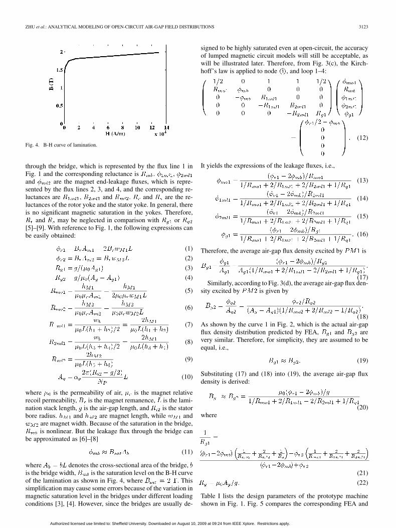
Fig. 4. B-H curve of lamination.
through the bridge, which is represented by the flux line 1 inFig. 1 and the corresponding reluctance is . ,and are the magnet end-leakage fluxes, which is repre-sented by the flux lines 2, 3, and 4, and the corresponding re-luctances are , and . and are the re-luctances of the rotor yoke and the stator yoke. In general, thereis no significant magnetic saturation in the yokes. Therefore,
and may be neglected in comparison with or[5]–[9]. With reference to Fig. 1, the following expressions canbe easily obtained:
(1)
(2)
(3)
(4)
(5)
(6)
(7)
(8)
(9)
(10)
where is the permeability of air, is the magnet relativerecoil permeability, is the magnet remanence, is the lami-nation stack length, is the air-gap length, and is the statorbore radius. and are magnet length, while and
are magnet width. Because of the saturation in the bridge,is nonlinear. But the leakage flux through the bridge can
be approximated as [6]–[8]
(11)
where denotes the cross-sectional area of the bridge,is the bridge width, is the saturation level on the B-H curveof the lamination as shown in Fig. 4, where . Thissimplification may cause some errors because of the variation inmagnetic saturation level in the bridges under different loadingconditions [3], [4]. However, since the bridges are usually de-
signed to be highly saturated even at open-circuit, the accuracyof lumped magnetic circuit models will still be acceptable, aswill be illustrated later. Therefore, from Fig. 3(c), the Kirch-hoff’s law is applied to node , and loop 1–4:
(12)
It yields the expressions of the leakage fluxes, i.e.,
(13)
(14)
(15)
(16)
Therefore, the average air-gap flux density excited by is
(17)Similarly, according to Fig. 3(d), the average air-gap flux den-
sity excited by is given by
(18)As shown by the curve 1 in Fig. 2, which is the actual air-gapflux density distribution predicted by FEA, and arevery similar. Therefore, for simplicity, they are assumed to beequal, i.e.,
(19)
Substituting (17) and (18) into (19), the average air-gap fluxdensity is derived:
(20)where
(21)
(22)
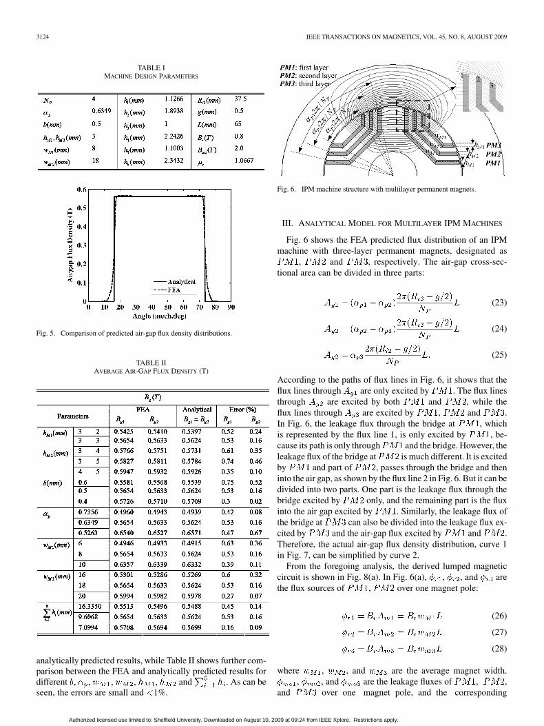
Table I lists the design parameters of the prototype machineshown in Fig. 1. Fig. 5 compares the corresponding FEA and
Authorized licensed use limited to: Sheffield University. Downloaded on August 10, 2009 at 09:24 from IEEE Xplore. Restrictions apply.
3124 IEEE TRANSACTIONS ON MAGNETICS, VOL. 45, NO. 8, AUGUST 2009
TABLE IMACHINE DESIGN PARAMETERS
Fig. 5. Comparison of predicted air-gap flux density distributions.
TABLE IIAVERAGE AIR-GAP FLUX DENSITY (T)
analytically predicted results, while Table II shows further com-parison between the FEA and analytically predicted results fordifferent , , , , , and . As can beseen, the errors are small and 1%.
Fig. 6. IPM machine structure with multilayer permanent magnets.
III. ANALYTICAL MODEL FOR MULTILAYER IPM MACHINES
Fig. 6 shows the FEA predicted flux distribution of an IPM
machine with three-layer permanent magnets, designated as
, and , respectively. The air-gap cross-sec-
tional area can be divided in three parts:
(23)
(24)
(25)
According to the paths of flux lines in Fig. 6, it shows that the
flux lines through are only excited by . The flux lines
through are excited by both and , while the
flux lines through are excited by , and .
In Fig. 6, the leakage flux through the bridge at , which
is represented by the flux line 1, is only excited by , be-
cause its path is only through and the bridge. However, the
leakage flux of the bridge at is much different. It is excited
by and part of , passes through the bridge and then
into the air gap, as shown by the flux line 2 in Fig. 6. But it can be
divided into two parts. One part is the leakage flux through the
bridge excited by only, and the remaining part is the flux
into the air gap excited by . Similarly, the leakage flux of
the bridge at can also be divided into the leakage flux ex-
cited by and the air-gap flux excited by and .
Therefore, the actual air-gap flux density distribution, curve 1
in Fig. 7, can be simplified by curve 2.
From the foregoing analysis, the derived lumped magnetic
circuit is shown in Fig. 8(a). In Fig. 6(a), , , and are
the flux sources of , over one magnet pole:
(26)
(27)
(28)
where , , and are the average magnet width.
, , and are the leakage fluxes of , ,
and over one magnet pole, and the corresponding
Authorized licensed use limited to: Sheffield University. Downloaded on August 10, 2009 at 09:24 from IEEE Xplore. Restrictions apply.
ZHU et al.: ANALYTICAL MODELING OF OPEN-CIRCUIT AIR-GAP FIELD DISTRIBUTIONS 3125
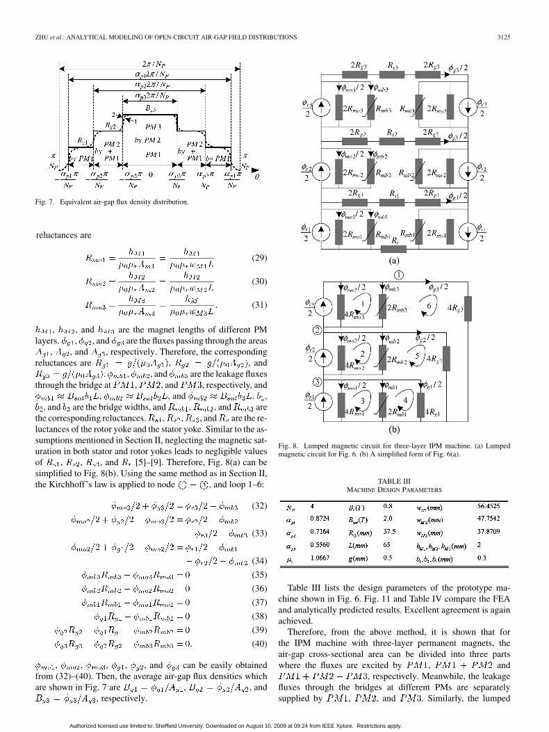
Fig. 7. Equivalent air-gap flux density distribution.
reluctances are
(29)
(30)
(31)
, , and are the magnet lengths of different PM
layers. , , and are the fluxes passing through the areas
, , and , respectively. Therefore, the corresponding
reluctances are , , and
. , , and are the leakage fluxes
through the bridge at , , and , respectively, and
, , and . ,
, and are the bridge widths, and , , and are
the corresponding reluctances. , , , and are the re-
luctances of the rotor yoke and the stator yoke. Similar to the as-
sumptions mentioned in Section II, neglecting the magnetic sat-
uration in both stator and rotor yokes leads to negligible values
of , , , and [5]–[9]. Therefore, Fig. 8(a) can be
simplified to Fig. 8(b). Using the same method as in Section II,
the Kirchhoff’s law is applied to node , and loop 1–6:
(32)
(33)
(34)
(35)
(36)
(37)
(38)
(39)
(40)
, , , , , and can be easily obtained
from (32)–(40). Then, the average air-gap flux densities which
are shown in Fig. 7 are , , and
, respectively.
Fig. 8. Lumped magnetic circuit for three-layer IPM machine. (a) Lumpedmagnetic circuit for Fig. 6. (b) A simplified form of Fig. 6(a).
TABLE IIIMACHINE DESIGN PARAMETERS
Table III lists the design parameters of the prototype ma-
chine shown in Fig. 6. Fig. 11 and Table IV compare the FEA
and analytically predicted results. Excellent agreement is again
achieved.
Therefore, from the above method, it is shown that for
the IPM machine with three-layer permanent magnets, the
air-gap cross-sectional area can be divided into three parts
where the fluxes are excited by , and
, respectively. Meanwhile, the leakage
fluxes through the bridges at different PMs are separately
supplied by , , and . Similarly, the lumped
Authorized licensed use limited to: Sheffield University. Downloaded on August 10, 2009 at 09:24 from IEEE Xplore. Restrictions apply.
3126 IEEE TRANSACTIONS ON MAGNETICS, VOL. 45, NO. 8, AUGUST 2009
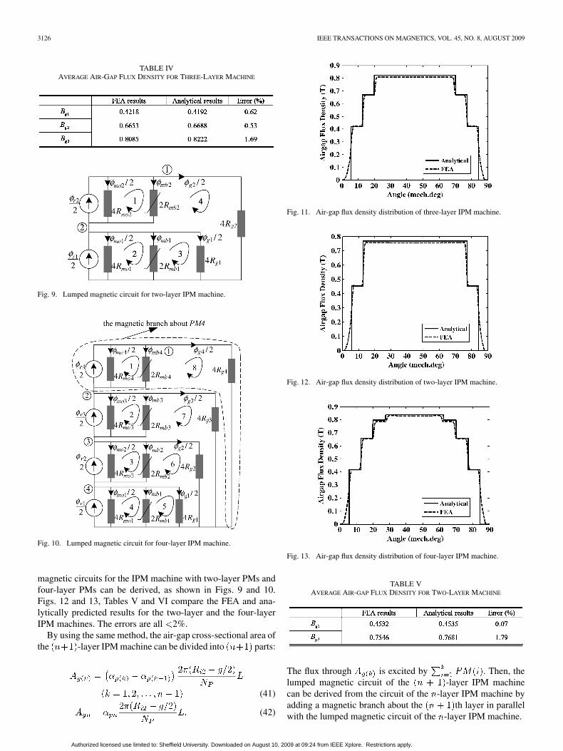
TABLE IVAVERAGE AIR-GAP FLUX DENSITY FOR THREE-LAYER MACHINE
Fig. 9. Lumped magnetic circuit for two-layer IPM machine.
Fig. 10. Lumped magnetic circuit for four-layer IPM machine.
magnetic circuits for the IPM machine with two-layer PMs and
four-layer PMs can be derived, as shown in Figs. 9 and 10.
Figs. 12 and 13, Tables V and VI compare the FEA and ana-
lytically predicted results for the two-layer and the four-layer
IPM machines. The errors are all 2%.
By using the same method, the air-gap cross-sectional area of
the -layer IPM machine can be divided into parts:
(41)
(42)
Fig. 11. Air-gap flux density distribution of three-layer IPM machine.
Fig. 12. Air-gap flux density distribution of two-layer IPM machine.
Fig. 13. Air-gap flux density distribution of four-layer IPM machine.
TABLE VAVERAGE AIR-GAP FLUX DENSITY FOR TWO-LAYER MACHINE
The flux through is excited by . Then, the
lumped magnetic circuit of the -layer IPM machine
can be derived from the circuit of the -layer IPM machine by
adding a magnetic branch about the th layer in parallel
with the lumped magnetic circuit of the -layer IPM machine.
Authorized licensed use limited to: Sheffield University. Downloaded on August 10, 2009 at 09:24 from IEEE Xplore. Restrictions apply.

ZHU et al.: ANALYTICAL MODELING OF OPEN-CIRCUIT AIR-GAP FIELD DISTRIBUTIONS 3127
TABLE VIAVERAGE AIR-GAP FLUX DENSITY FOR TWO-LAYER MACHINE
Fig. 14. Influence of magnet width on air-gap flux density �� � �������.
Fig. 15. Influence of pole-arc to pole-pitch ratio on air-gap flux density �� ��� �.
IV. OPTIMIZATION WITH ANALYTICAL MODEL
In order to achieve high torque density, high efficiency, and
low torque ripple, it is desirable to maximize the fundamental
air-gap flux density and minimize the THD of air-gap flux den-
sity. The EMF waveform is directly related to the air-gap field
distribution and the winding configuration. Particularly, if the
windings are concentrated and fully pitched, the EMF waveform
will be identical to the air-gap field distribution. Therefore, the
optimization of air-gap flux density is an important design issue.
With the developed lumped magnetic circuit models, such opti-
mization is much easier than that with FEA.
A. Optimization of Multisegment IPM Machines
For the prototype multisegmented IPM machine in Table I,
, , or can be optimized for maximum peak funda-
mental air-gap flux density or minimum THD of air-gap flux
density with the lumped magnetic circuit model. In Fig. 14,
is the amplitude of the fundamental component of the air-gap
flux density . Total magnet width is ,
which represents the magnet volume. If the pole-arc to pole-
pitch ratio remains constant, and increases with the in-
Fig. 16. Influence of pole-arc to pole-pitch ratio and total magnet width onair-gap flux density.
Fig. 17. Optimized multisegment IPM machine. (a) Rotor. (b) Air-gap fielddistribution.
TABLE VIICOMPARISON OF FEA AND ANALYTICALLY PREDICTED RESULTS OF OPTIMIZED
MULTISEGMENT IPM MACHINE
crease of magnet volume, but the THD remains constant, as
shown in Fig. 14. If the magnet volume remains constant, the
air-gap flux density and its amplitude of the fundamental com-
ponent decrease as the pole-arc to pole-pitch ratio is increased,
Fig. 15. In Fig. 16, the magnet width and are increased in
order to obtain the same air-gap flux density . It can be seen
from Fig. 16, if remains constant, will increase with
, while THD variation in Fig. 16 is exactly the same as that in
Fig. 15, which indicates that THD is only related to . Clearly,
there is an optimal pole-arc to pole-pitch ratio, viz. ,
for minimum THD. When and , the
cross section of the rotor and corresponding air-gap field dis-
tribution are shown in Fig. 17. Table VII compares FEA and
analytically predicted results. They have very good agreement.
B. Optimization of Multilayer IPM Machines
For the prototype multilayer IPM machine in Table III, the
influence of number of PM layers and displacement of different
Authorized licensed use limited to: Sheffield University. Downloaded on August 10, 2009 at 09:24 from IEEE Xplore. Restrictions apply.
3128 IEEE TRANSACTIONS ON MAGNETICS, VOL. 45, NO. 8, AUGUST 2009
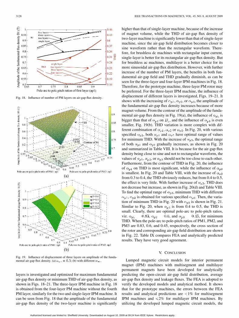
Fig. 18. Influence of number of PM layers on air-gap flux density.
Fig. 19. Influence of displacement of three layers on amplitude of the funda-mental air-gap flux density. (a) � � ���; (b) with different � .
layers is investigated and optimized for maximum fundamental
air-gap flux density or minimum THD of air-gap flux density, as
shown in Figs. 18–21. The three-layer IPM machine in Fig. 18
is obtained from the four-layer PM machine without the fourth
PM layer, similarly for the two and single-layer IPM machine. It
can be seen from Fig. 18 that the amplitude of the fundamental
air-gap flux density of the two-layer machine is significantly
higher than that of single-layer machine, because of the increase
of magnet volume, while the THD of air-gap flux density of
two-layer machine is significantly lower than that of single-layer
machine, since the air-gap field distribution becomes closer to
sine waveform rather than the rectangular waveform. There-
fore, for brushless dc machines with rectangular input current,
single-layer is better for its rectangular air-gap flux density. But
for brushless ac machines, multilayer is a better choice for its
more sinusoidal air-gap flux distribution. However, with further
increase of the number of PM layers, the benefits in both fun-
damental air-gap field and THD gradually diminish, as can be
seen for the three-layer and four-layer IPM machines in Fig. 18.
Therefore, for the prototype machine, three-layer PM rotor may
be preferred. For the three-layer IPM machine, the influence of
displacement of different layers is investigated, Figs. 19–21. It
shows with the increasing of , , or , the amplitude of
the fundamental air-gap flux density increases because of more
magnet volume. From the contour of the amplitude of the funda-
mental air-gap flux density in Fig. 19(a), the influence of is
bigger than that of on , and the influence of is even
smaller, Fig. 19(b). THD variation is more complex with dif-
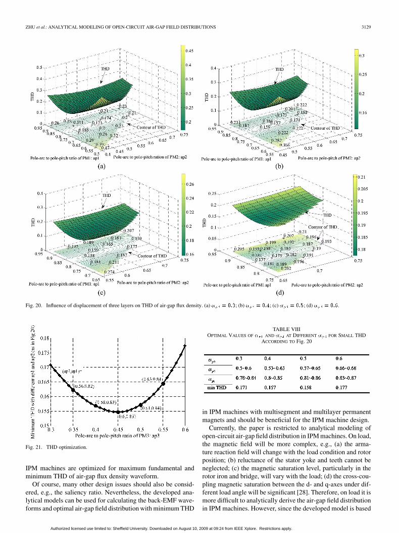
ferent combination of , or . In Fig. 20, with various
specified , both and have optimal range of values
for minimum THD. With the increase of , the optimal range
of both and gradually increases, as shown in Fig. 20
and summarized in Table VIII. It is because for the air-gap flux
density being close to sine and not to rectangular waveform, the
values of , , or should not be too close to each other.
Furthermore, from the contour of THD in Fig. 20, the influence
of on THD is most significant, while the influence of
is smallest. In Fig. 20 and Table VIII, with the increase of
from 0.3 to 0.4, the THD obviously reduces, but from 0.4 to 0.5,
the effect is very little. With further increase of , THD does
not decrease but increase, as shown in Fig. 20(d) and Table VIII.
To find the optimal range of , minimum THD with different
, is obtained for various specified . Then, the varia-
tion of minimum THD in Fig. 20 with is shown in Fig. 21.
Similar to Fig. 20, when is from 0.4 to 0.5, the THD is
small. Clearly, there are optimal pole-arc to pole-pitch ratios,
viz. , , and , for minimum
THD. When the pole-arc to pole-pitch ratios of PM1, PM2, and
PM3 are 0.83, 0.6, and 0.45, respectively, the cross section of
the rotor and corresponding air-gap field distribution are shown
in Fig. 22. Table IX compares FEA and analytically predicted
results. They have very good agreement.
V. CONCLUSION
Lumped magnetic circuit models for interior permanent
magnet (IPM) machines with multisegment and multilayer
permanent magnets have been developed for analytically
predicting the open-circuit air-gap field distribution, average
air-gap flux density and leakage fluxes. The FEA is adopted to
verify the developed models and analytical method. It shows
that for the prototype machines, the errors between the FEA
results and analytical predictions are 1% for multisegment
IPM machines and 2% for multilayer IPM machines. By
utilizing the developed lumped magnetic circuit models, the
Authorized licensed use limited to: Sheffield University. Downloaded on August 10, 2009 at 09:24 from IEEE Xplore. Restrictions apply.
ZHU et al.: ANALYTICAL MODELING OF OPEN-CIRCUIT AIR-GAP FIELD DISTRIBUTIONS 3129
Fig. 20. Influence of displacement of three layers on THD of air-gap flux density. (a) � � ���; (b) � � ���; (c) � � ���; (d) � � ���.
Fig. 21. THD optimization.
IPM machines are optimized for maximum fundamental and
minimum THD of air-gap flux density waveform.
Of course, many other design issues should also be consid-
ered, e.g., the saliency ratio. Nevertheless, the developed ana-
lytical models can be used for calculating the back-EMF wave-
forms and optimal air-gap field distribution with minimum THD
TABLE VIIIOPTIMAL VALUES OF � AND � AT DIFFERENT � FOR SMALL THD
ACCORDING TO Fig. 20
in IPM machines with multisegment and multilayer permanent
magnets and should be beneficial for the IPM machine design.
Currently, the paper is restricted to analytical modeling of
open-circuit air-gap field distribution in IPM machines. On load,
the magnetic field will be more complex, e.g., (a) the arma-
ture reaction field will change with the load condition and rotor
position; (b) reluctance of the stator yoke and teeth cannot be
neglected; (c) the magnetic saturation level, particularly in the
rotor iron and bridge, will vary with the load; (d) the cross-cou-
pling magnetic saturation between the d- and q-axes under dif-
ferent load angle will be significant [28]. Therefore, on load it is
more difficult to analytically derive the air-gap field distribution
in IPM machines. However, since the developed model is based
Authorized licensed use limited to: Sheffield University. Downloaded on August 10, 2009 at 09:24 from IEEE Xplore. Restrictions apply.

3130 IEEE TRANSACTIONS ON MAGNETICS, VOL. 45, NO. 8, AUGUST 2009
Fig. 22. Optimized multilayer IPM machine. (a) Rotor. (b) Air-gap fielddistribution.
TABLE IXCOMPARISON OF FEA AND ANALYTICALLY PREDICTED RESULTS OF OPTIMIZED
MULTILAYER IPM MACHINE
on the lumped magnetic circuit model, it can be extended, sim-
ilar to [3]–[9], to accounting for the nonlinear magnetic prop-
erty of stator yoke and teeth, rotor irons, bridges and yoke, etc.,
together with the effect of stator slotting and armature current,
which is being carried out and will be reported in a future paper.
REFERENCES
[1] T. J. E. Miller, Brushless Permanent-Magnet and Reluctance Motor
Drives. New York: Oxford University Press, 1989.[2] T. M. Jahns and V. Blasko, “Recent advances in power electronics tech-
nology for industrial and traction machine drives,” Proc. IEEE, vol. 89,no. 6, pp. 963–975, Jun. 2001.
[3] C. Mi, M. Filippa, W. Liu, and R. Q. Ma, “Analytical method for pre-dicting the air-gap flux of interior-type permanent-magnet machines,”IEEE Trans. Magn., vol. 40, no. 1, pp. 50–58, Jan. 2004.
[4] S. H. Han, T. M. Jahns, and W. L. Soong, “A magnetic circuit model foran IPM synchronous machine incorporating moving arigap and cross-coupled saturation effects,” in Proc. IEEE Int. Electric Machines and
Drives Conf. (IEMDC), May 3–5, 2007, pp. 21–26.[5] N. Matsui, M. Nakamura, and T. Kosaka, “Instantaneous torque anal-
ysis of hybrid stepping motor,” IEEE Trans. Ind. Appl., vol. 32, no. 5,pp. 1176–1182, 1996.
[6] W. B. Tsai and T. Y. Chang, “Analysis of flux leakage in a brush-less permanent-magnet motor with embedded magnets,” IEEE Trans.
Magn., vol. 35, no. 1, pp. 543–547, Jan. 1999.[7] C. C. Hwang and Y. H. Cho, “Effects of leakage flux on magnetic
fields of interior permanent magnet synchronous motors,” IEEE Trans.
Magn., vol. 37, no. 4, pp. 3021–3024, Jul. 2001.[8] E. C. Lovelace, T. M. Jahns, and J. H. Lang, “A saturating lumped pa-
rameter model for an interior PM synchronous machine,” IEEE Trans.
Ind. Appl., vol. 38, no. 3, pp. 645–650, 2002.[9] M. A. Rahman, T. A. Little, and G. R. Slemon, “Analytical models
for interior-type permanent magnet synchronous motors,” IEEE Trans.
Magn., vol. MAG-21, no. 5, pp. 1741–1743, Sep. 1985.
[10] Z. Q. Zhu, D. Howe, E. Bolte, and B. Ackermann, “Instantaneous mag-netic field distribution in brushless permanent magnet dc motors, partI: Open-circuit field,” IEEE Trans. Magn., vol. 29, no. 1, pp. 124–135,Jan. 1993.
[11] Z. Q. Zhu, D. Howe, and C. C. Chan, “Improved analytical modelfor predicting the magnetic field distribution in brushless permanent-magnet machines,” IEEE Trans. Magn., vol. 38, no. 1, pp. 229–238,Jan. 2002.
[12] Z. Q. Zhu, D. Howe, and Z. P. Xia, “Prediction of open-circuit airgapfield distribution in brushless machines having an inset permanentmagnet rotor topology,” IEEE Trans. Magn., vol. 30, no. 1, pp. 98–107,Jan. 1994.
[13] D. Zarko, D. Ban, and T. A. Lipo, “Analytical calculation of magneticfield distribution in the slotted air gap of a surface permanent-magnetmotor using complex relative air-gap permeance,” IEEE Trans. Magn.,vol. 42, no. 7, pp. 1828–1837, Jul. 2006.
[14] Z. Q. Zhu and D. Howe, “Instantaneous magnetic field distribution inbrushless permanent magnet dc motors, part III: Effect of stator slot-ting,” IEEE Trans. Magn., vol. 29, no. 1, pp. 143–151, Jan. 1993.
[15] D. Zarko, D. Ban, and T. A. Lipo, “Analytical solution for coggingtorque in surface permanent-magnet motors using conformal map-ping,” IEEE Trans. Magn., vol. 44, no. 1, pp. 52–65, Jan. 2008.
[16] A. Kiyoumarisi, M. R. Hassanzadeh, and M. Moallem, “A new ana-lytical method on the field calculation of interior permanent-magnetsynchronous motors,” Scientica Iranica, vol. 13, no. 4, pp. 364–372,2006.
[17] F. Liang, S. O. Kwon, and J. P. Hong, “Conformal transformation tech-nique for prediction of the magnetic field distribution in an IPM motor,”in Proc. Eighth Int. Conf. Electrical Machines and Systems (ICEMS),2005, vol. 3, pp. 2124–2128.
[18] R. Qu and T. A. Lipo, “Analysis and modeling of air-gap and zigzagleakage fluxes in a surface-mounted permanent-magnet machine,”IEEE Trans. Ind. Appl., vol. 40, no. 1, pp. 121–127, 2004.
[19] J. P. Wang, D. K. Lieu, W. L. Lorimer, and A. Hartman, “Comparisonof lumped parameter and finite element magnetic modeling in a brush-less DC motor,” IEEE Trans. Magn., vol. 33, no. 5, pp. 4092–4094,Sep. 1997.
[20] Y. Kano, T. Kosaka, and N. Matsui, “Simple nonlinear magnetic anal-ysis for permanent-magnet motors,” IEEE Trans. Ind. Appl., vol. 41,no. 5, pp. 1205–1214, 2005.
[21] M. Moallen and G. E. Dawson, “An improved magnetic equivalentcircuit method for predicting the characteristics of highly saturatedelectromagnetic devices,” IEEE Trans. Magn., vol. 34, no. 5, pp.3632–3635, Sep. 1998.
[22] J. K. Kim, S. W. Joo, S. C. Hahn, J. P. Hong, D. H. Kang, and D.H. Koo, “Static characteristics of linear BLDC motor using equivalentmagnetic circuit and finite element method,” IEEE Trans. Magn., vol.40, no. 2, pp. 742–745, Mar. 2004.
[23] K. Shima, K. Ide, M. Takahashi, and K. Oka, “Steady-state magneticcircuit analysis of salient-pole synchronous machines consideringcross-magnetization,” IEEE Trans. Energy Convers., vol. 18, no. 2,pp. 213–218, 2003.
[24] Z. Q. Zhu, Y. Pang, D. Howe, S. Iwasaki, R. Deodhar, and A. Pride,“Analysis of electromagnetic performance of flux-switching per-manent-magnet machines by nonlinear adaptive lumped parametermagnetic circuit model,” IEEE Trans. Magn., vol. 41, no. 11, pp.4277–4287, Nov. 2005.
[25] Y. Chen, Z. Q. Zhu, and D. Howe, “3-D lumped parameter magneticcircuit analysis of single-phase flux-switching permanent magnetmotor,” IEEE Trans. Ind. Appl., vol. 44, no. 6, pp. 1701–1710, 2008.
[26] M. Cheng, K. T. Chau, C. C. Chan, E. Zhou, and X. Huang, “Nonlinearvarying-network magnetic circuit analysis for doubly salient perma-nent-magnet motors,” IEEE Trans. Magn., vol. 36, no. 1, pp. 339–348,Jan. 2000.
[27] D. C. Hanselman, Brushless Permanent-Magnet Motor Design. NewYork: McGraw-Hill, 1994.
[28] G. Qi, J. T. Chen, Z. Q. Zhu, D. Howe, L. B. Zhou, and C. L. Gu,“Influence of skew and cross-coupling on flux-weakening performanceof PM brushless AC machines,” IEEE Trans. Magn., vol. 45, no. 5, pp.2110–2117, May 2009.
Authorized licensed use limited to: Sheffield University. Downloaded on August 10, 2009 at 09:24 from IEEE Xplore. Restrictions apply.