analytical design planning technique: a model of the detailed building design process
TRANSCRIPT

In recent times there has been a growing understanding of the impor-tance of effective design management to facilitate a coordinated designwithin budget, and to ensure the smooth running of the project. Tra-
ditionally, building design has been planned by the same methods used toprogramme construction. These techniques do not allow the effect of vari-ations and delays to be fully understood within an iterative process suchas design. They monitor progress based upon the completion of drawingwork and other ‘design deliverables’ as opposed to the availability of keypieces of information. The ADePT methodology shown in Figure 1 wasdevised to overcome these limitations1, and associated computer tools havebeen developed to facilitate more effective planning and management ofbuilding design2. The first stage of the methodology is a model of thebuilding design process, representing design activities and their informationrequirements. The data in this model are linked via a dependency table toa dependency structure matrix (DSM) analysis tool3 which is used in thesecond stage to identify iteration within the design process and schedulethe activities with the objective of optimising the task order. The third
1 Austin, S, Baldwin, A andNewton, A ‘A data flow model toplan and manage the buildingdesign process’ Journal ofEngineering Design Vol 7 No 1(1996) pp 3–252 Austin, S, Baldwin, A, Li, Band Waskett, P Development ofthe ADePT methodology: aninterim report on the link IDAC100 Project Loughborough Uni-versity, Loughborough (1998)3 Steward, D Analysis andmanagement: structure, strategyand design Petrocelli Books,Princeton, NJ, USA (1981)
0142-694X/99 $ - see front matterDesign Studies20 (1999) 279–296279PII: S0142-694X(98)00038-6
1999 Elsevier Science Ltd All rights reserved Printed in Great Britain
DST: design studies (page 1 ) 08-03-99 12:29:20 Rev 14.02x ZDST$$160H
Analytical Design PlanningTechnique: a model of the detailedbuilding design process
Simon Austin, Andrew Baldwin, Baizhan Li and Paul Waskett,Department of Civil and Building Engineering, LoughboroughUniversity, Loughborough LE11 3TU, UK
Current planning practice takes little account of the interdisciplinary,iterative nature of the building design process. This leads to acompromised design process containing inevitable cycles of reworktogether with associated time and cost penalties in both design andconstruction. The Analytical Design Planning Technique (ADePT) is aplanning methodology which helps to overcome these difficulties. Thispaper describes the development of a modelling notation and model ofthe detailed building design process, which forms the first stage ofADePT. 1999 Elsevier Science Ltd. All rights reserved
Keywords: design management, design techniques, modelling, planning,information processing

4 Austin, S, Baldwin, A, Li, Band Waskett, P ‘Application ofthe Analytical Design PlanningTechnique to construction pro-ject management’ Project Man-agement Journal (submitted)5 Austin, S, Baldwin, A, Li, Band Waskett, P ‘AnalyticalDesign Planning Technique(ADePT): a dependency struc-ture matrix tool to schedule thebuilding design process’ Con-struction Management and Eco-nomics (in press)6 Austin, S, Baldwin, A, Li, Band Waskett, P ‘AnalyticalDesign Planning Technique(ADePT): programming thebuilding design process’ Struc-tures and Building (in press)
stage of the methodology produces design programmes based on theoptimised process sequence. The technique requires some iteration betweenthe matrix and programming stages.
This paper describes a review of existing design models and modellingtechniques, the establishment of a modelling notation to suit the buildingdesign process, the development and validation of a non-specific designprocess model (DPM) and the testing of this model, via the formulationof project-specific models. A full exposition of the complete ADePT meth-odology and detailed descriptions of the dependency structure matrix andprogramming stages are given elsewhere4–6.
1 Models of design processesSince the 1970s many models of the design process, both descriptive andprescriptive, and general and specific to a particular application, have beendevised. This represents a clear recognition that attempts should be madeto understand the process.
280 Design Studies Vol 20 No 3 May 1999
DST: design studies (page 2 ) 08-03-99 12:29:20 Rev 14.02x ZDST$$160H
Figure 1 Analytical Design Planning Technique (ADePT)
7 Pugh, S ‘Design activity mod-els: worldwide emergence andconvergence’ Design StudiesVol 7 No 3 (1986) pp 167–1738 VDI-Richtlinie 2221(Entwurf) Methodik zumentwickeln und konstruierentechnischer systeme und pro-dukte VDI-Verlag, Dusseldorf(1985)9 Pahl, G and Beitz, W Engin-eering design: a systematicapproach The Design Council,London (1988)10 RIBA Plan of Work forDesign Team Operation RoyalInstitute of British Architects,RIBA Publications, London(1973)11 Pugh, S and Morley, I ETotal design: towards a theory oftotal design Design Division, Uni-versity of Strathclyde, Glasgow(1988)12 Pugh, S Total design Wiley,London (1990)13 Sheath, D M, Woolley, H,Cooper, R, Hinks, J andAouad, G A Process forchange—the development of ageneric design and constructionprotocol for the UK constructionindustry In International Con-struction Information Technology(INCIT 96) Conference Sydney,Australia (1996)14 Sanvido, V E and Norton,KJ ‘Integrated design-processmodel ’ Journal of Managementin Engineering VolSeptember/October (1994)pp 55–6215 Karhu, V, Keitila¨ , M andLahdenpera , P Constructionprocess model: generic present-state systematisation by IDEF0Research Notes 1845 VTT, Fin-land (1997)16 Baldwin, A, Austin, S,Thorpe, A and Hassan, T Simu-lating quality within the designprocess. In American Society ofCivil Engineers (ASCE) SecondCongress on Computing in CivilEngineering Atlanta, Georgia(1995) pp 1475–1482
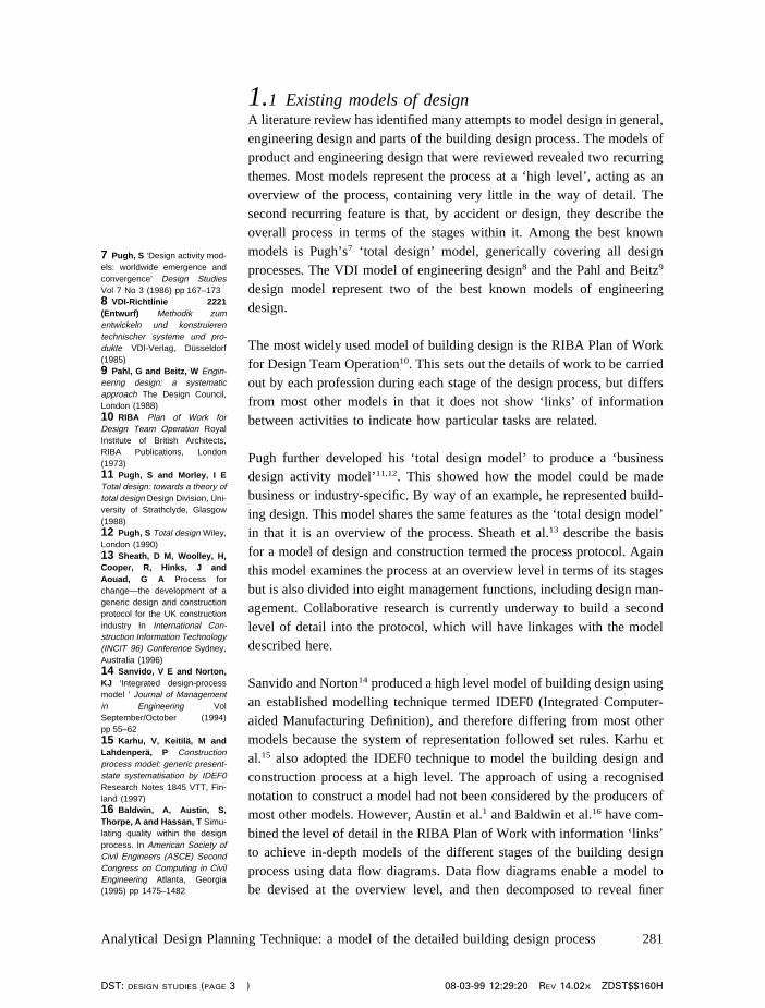
1.1 Existing models of designA literature review has identified many attempts to model design in general,engineering design and parts of the building design process. The models ofproduct and engineering design that were reviewed revealed two recurringthemes. Most models represent the process at a ‘high level’, acting as anoverview of the process, containing very little in the way of detail. Thesecond recurring feature is that, by accident or design, they describe theoverall process in terms of the stages within it. Among the best knownmodels is Pugh’s7 ‘total design’ model, generically covering all designprocesses. The VDI model of engineering design8 and the Pahl and Beitz9
design model represent two of the best known models of engineeringdesign.
The most widely used model of building design is the RIBA Plan of Workfor Design Team Operation10. This sets out the details of work to be carriedout by each profession during each stage of the design process, but differsfrom most other models in that it does not show ‘links’ of informationbetween activities to indicate how particular tasks are related.
Pugh further developed his ‘total design model’ to produce a ‘businessdesign activity model’11,12. This showed how the model could be madebusiness or industry-specific. By way of an example, he represented build-ing design. This model shares the same features as the ‘total design model’in that it is an overview of the process. Sheath et al.13 describe the basisfor a model of design and construction termed the process protocol. Againthis model examines the process at an overview level in terms of its stagesbut is also divided into eight management functions, including design man-agement. Collaborative research is currently underway to build a secondlevel of detail into the protocol, which will have linkages with the modeldescribed here.
Sanvido and Norton14 produced a high level model of building design usingan established modelling technique termed IDEF0 (Integrated Computer-aided Manufacturing Definition), and therefore differing from most othermodels because the system of representation followed set rules. Karhu etal.15 also adopted the IDEF0 technique to model the building design andconstruction process at a high level. The approach of using a recognisednotation to construct a model had not been considered by the producers ofmost other models. However, Austin et al.1 and Baldwin et al.16 have com-bined the level of detail in the RIBA Plan of Work with information ‘links’to achieve in-depth models of the different stages of the building designprocess using data flow diagrams. Data flow diagrams enable a model tobe devised at the overview level, and then decomposed to reveal finer
Analytical Design Planning Technique: a model of the detailed building design process 281
DST: design studies (page 3 ) 08-03-99 12:29:20 Rev 14.02x ZDST$$160H

17 Marca, D A and McGowen,C L SADT: Structured Analysisand Design Technique McGraw-Hill, New York (1988)18 Bravoco, R R and Yadav,S B A ‘Methodology to model thedynamic structure of an organis-ation’ Information Systems Vol10 No 3 (1985) pp 299–31719 Court, A W, Culley, S Jand McMahon, C A ‘Informationaccess diagrams: a technique foranalysing the usage of designinformation’ Journal of Engineer-ing Design Vol 7 No 1 (1996)pp 55–75
detail. Baldwin et al.16 produced a model of the concept and scheme designstages of a project, while Austin et al.1 developed a model of the civil andstructural engineering elements of the detailed design stage. These works,and those of Sanvido and Norton14 and Karhu et al.15, each developed amodel of building design using a recognised modelling technique becausethey required their models to be of use as part of broader, more com-plex systems.
1.2 Modelling techniquesMany modelling methodologies have been examined to identify one thatis most suited to representing information flow in detailed building design.Possible methodologies include: data flow diagrams; IDEF techniques(including IDEF0); entity relationship diagrams; hierarchical plus input–process–output diagrams; Jackson diagrams; object-orientated modellingsystems; and Petri nets. Each of these techniques has advantages in model-ling certain types of activity or data. Data flow diagrams and IDEF0 wereidentified as the most suitable techniques to produce a model of buildingdesign for use in the wider context of the ADePT methodology. The twotechniques offer similar features, but data flow diagrams were originallyfavoured because of the work of Austin et al.1. However, following adetailed evaluation of the two methodologies and a review of recent trendsin process modelling, it was decided that IDEF0 would be the most appro-priate notation.
1.2.1 IDEF0 modellingThe IDEF methodologies were devised in the 1970s for use in the USaerospace industry. By the mid-1970s they were in use in Europe and arenow notable among modelling techniques for their wide range of usage,particularly IDEF017. IDEF techniques were developed in order to bettercommunicate and analyse manufacturing in an attempt to improve pro-ductivity. This would be achieved through modelling information, dynam-ics and functions and processes18. Court et al.19 undertook a comparison ofvarious modelling techniques, including the IDEF techniques. Functionalmodelling is achieved with IDEF0. A process can be represented from theviewpoint of the information within it, rather than of its subprocesses,which has been identified as a requirement of a building design model.The technique is easy to use and understand, which is very important ifthe model is to be modified very quickly at the start of a building projectand maintained throughout it. Each activity in the process transforms aninformation input into an output, and the internal mechanics of that trans-formation are not modelled. Figure 2 shows the notation of the IDEF0technique. Each activity or process can be partitioned to show finer detailon another diagram, ensuring a single diagram does not become too cum-bersome.
282 Design Studies Vol 20 No 3 May 1999
DST: design studies (page 4 ) 08-03-99 12:29:20 Rev 14.02x ZDST$$160H
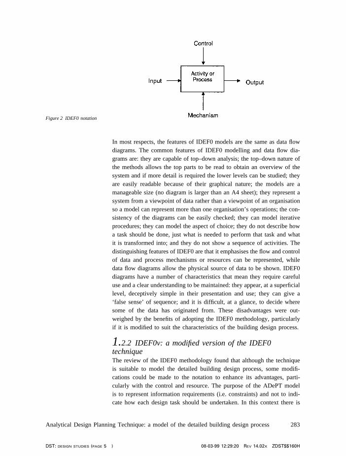
In most respects, the features of IDEF0 models are the same as data flowdiagrams. The common features of IDEF0 modelling and data flow dia-grams are: they are capable of top–down analysis; the top–down nature ofthe methods allows the top parts to be read to obtain an overview of thesystem and if more detail is required the lower levels can be studied; theyare easily readable because of their graphical nature; the models are amanageable size (no diagram is larger than an A4 sheet); they represent asystem from a viewpoint of data rather than a viewpoint of an organisationso a model can represent more than one organisation’s operations; the con-sistency of the diagrams can be easily checked; they can model iterativeprocedures; they can model the aspect of choice; they do not describe howa task should be done, just what is needed to perform that task and whatit is transformed into; and they do not show a sequence of activities. Thedistinguishing features of IDEF0 are that it emphasises the flow and controlof data and process mechanisms or resources can be represented, whiledata flow diagrams allow the physical source of data to be shown. IDEF0diagrams have a number of characteristics that mean they require carefuluse and a clear understanding to be maintained: they appear, at a superficiallevel, deceptively simple in their presentation and use; they can give a‘false sense’ of sequence; and it is difficult, at a glance, to decide wheresome of the data has originated from. These disadvantages were out-weighed by the benefits of adopting the IDEF0 methodology, particularlyif it is modified to suit the characteristics of the building design process.
1.2.2 IDEF0v: a modified version of the IDEF0techniqueThe review of the IDEF0 methodology found that although the techniqueis suitable to model the detailed building design process, some modifi-cations could be made to the notation to enhance its advantages, parti-cularly with the control and resource. The purpose of the ADePT modelis to represent information requirements (i.e. constraints) and not to indi-cate how each design task should be undertaken. In this context there is
Analytical Design Planning Technique: a model of the detailed building design process 283
DST: design studies (page 5 ) 08-03-99 12:29:20 Rev 14.02x ZDST$$160H
Figure 2 IDEF0 notation

little benefit to be gained from representing separate process controls inthe model. Also, activity mechanisms (architect, civil engineer, etc.) wouldshow little other than the discipline to which the activity belongs, and thisattribute is implicit from the hierarchical structure of the model. It wasdecided that better use could be made of the top and bottom arrow featuresof an IDEF0 diagram by distinguishing the information inputs that are fromactivities in the same discipline, from those in other disciplines and fromexternal sources such as the client, a regulating authority or an earlier stageof the design process. Discussions with designers and design managerssuggest that this is of benefit, since the different types of information flowrequire different management priorities.
Figure 3 shows the notation implemented in the detailed building designprocess model, termed IDEF0v, which varies from the standard IDEF0notation in the following ways:
(1) intra-disciplinary inputs enter from the left;(2) cross-disciplinary inputs enter from the top; and(3) inputs from external sources enter from the bottom.
Tools that enable IDEF0 models to be constructed automatically dis-tinguish between the different types of information input in a diagram.These tools will allow a model using IDEF0v to be compiled and willbe able to distinguish between the different information inputs in theirreporting facilities.
2 Creating the design process modelThe DPM of detailed building design was developed in two stages.Initially, the activities within the overall process were identified and theirhierarchical structure determined. Then the information requirements of
284 Design Studies Vol 20 No 3 May 1999
DST: design studies (page 6 ) 08-03-99 12:29:21 Rev 14.02x ZDST$$160H
Figure 3 Modified IDEF0
notation (IDEF0v)
each bottom level task were identified, allowing the DPM to be con-structed. This combination of top–down and bottom–up analytical activitiesand the general features of the model are described below.
2.1 Identifying the detailed building design hierarchyand tasks
2.1.1 Determining the design process hierarchyThe overall process of detailed building design is defined in terms of anumber of subprocesses and problems. Through a series of interviews withdesigners, design managers and design planners, this research has estab-lished a hierarchy of the subprocesses.
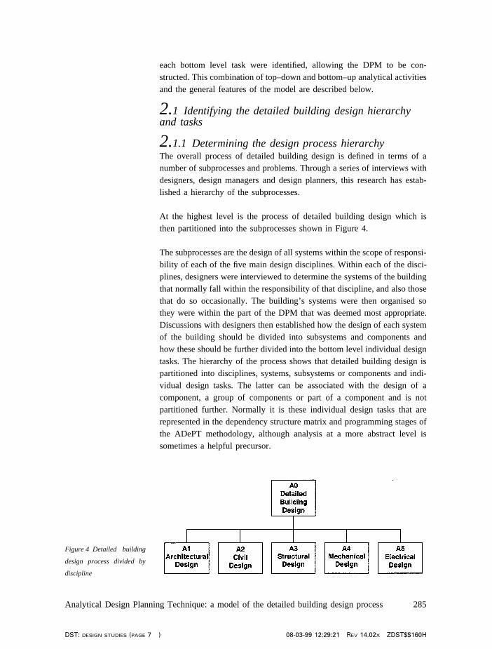
At the highest level is the process of detailed building design which isthen partitioned into the subprocesses shown in Figure 4.
The subprocesses are the design of all systems within the scope of responsi-bility of each of the five main design disciplines. Within each of the disci-plines, designers were interviewed to determine the systems of the buildingthat normally fall within the responsibility of that discipline, and also thosethat do so occasionally. The building’s systems were then organised sothey were within the part of the DPM that was deemed most appropriate.Discussions with designers then established how the design of each systemof the building should be divided into subsystems and components andhow these should be further divided into the bottom level individual designtasks. The hierarchy of the process shows that detailed building design ispartitioned into disciplines, systems, subsystems or components and indi-vidual design tasks. The latter can be associated with the design of acomponent, a group of components or part of a component and is notpartitioned further. Normally it is these individual design tasks that arerepresented in the dependency structure matrix and programming stages ofthe ADePT methodology, although analysis at a more abstract level issometimes a helpful precursor.
Analytical Design Planning Technique: a model of the detailed building design process 285
DST: design studies (page 7 ) 08-03-99 12:29:21 Rev 14.02x ZDST$$160H
Figure 4 Detailed building
design process divided by
discipline

2.1.2 Determining the information requirements of thetasksHaving established the hierarchy of the activities in the detailed buildingdesign process, the information dependencies of each individual designtask needed to be determined so that the DPM could be constructed. Thisinformation was collated in tabular form, via input from practising design-ers. The nature and source of each item of information was listed, regard-less of whether it would normally have been available during the designof a building. This means that all the information required to allow thedesign to proceed was considered. The task number of both the task underconsideration and the source activities within the same design disciplinewere determined by the process hierarchy.
2.1.3 Producing design process model diagramsThe DPM was compiled with a Computer-aided Software Engineering(CASE) tool, by placing on to each diagram the activities identified in theprocess hierarchy and the information flows that each activity required.The source activity of each intra- and cross-disciplinary information inputwas then identified. This was necessary because at the stage when infor-mation requirements were determined, the precise source of each item ofinformation could not be known, only its discipline. The information flowswere then attached to the appropriate tasks as either inputs or outputs usingthe IDEF0v notation described in Figure 3. The DPM consists of some150 diagrams, 600 design tasks and 4600 information requirements.
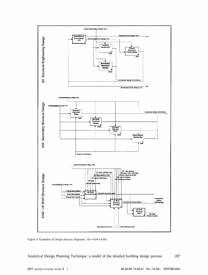
Figure 5 shows examples of diagrams from the detailed building designmodel. The DPM hierarchy can be traced from activity A3, ‘structuraldesign’, through activity A34, ‘secondary structure design’, and A342, ‘liftshaft structure design’ to design tasks at the bottom of the hierarchy(activities A3421, A3422, A3423). Activity A31, ‘check/revise structuraldesign information’ is also an individual design task. It is not partitionedor represented in the matrix analysis stage of the methodology because itdeals with grouped information rather than information produced andrequired by other design tasks. It can be seen that detailed informationflows are represented at the bottom level of the hierarchy; however, atupper levels, the information flows are grouped under headings that ensurethe diagrams do not become too confusing.
2.2 Verifying the design process modelFollowing its compilation, the consistency and integrity of each section ofthe building DPM was checked by the research team through the use offunctions within the proprietary CASE tool. The diagrams were then exam-ined by designers from a different organisation to the one which helped
286 Design Studies Vol 20 No 3 May 1999
DST: design studies (page 8 ) 08-03-99 12:29:21 Rev 14.02x ZDST$$160H
Analytical Design Planning Technique: a model of the detailed building design process 287
DST: design studies (page 9 ) 08-03-99 12:29:21 Rev 14.02x ZDST$$160H
Figure 5 Examples of design process diagrams: A3→A34→A342

in compiling them. This was, in effect, the first test of the hypothesis relat-ing to the construction of a largely non-specific (i.e. generic) design processfor buildings, and the result was very encouraging, considering the smalland relatively trivial changes required to suit the second organisation. Com-ments were incorporated into the diagrams, where appropriate, before asecond version of the diagrams was sent to both the design organisationsfor final comments and confirmation. The resulting non-specific design pro-cess model was then used as the basis for the creation of project-specificmodels on the case study projects (section 5). Clearly, further verificationof the model will occur as it is exposed to more design organisationsand projects.
2.3 Design information classification
2.3.1 Compiling design information classificationsThe dependency structure matrix analysis stage of the ADePT methodologynot only represents the activities in the DPM and the dependencies betweenthem, but indicates the level of dependency and schedules the process onthis basis. The information requirements were tabulated in the same formas was used to compile the DPM. Information classifications were allocatedto each information flow by practising designers from the collaboratingorganisations. Classifications were made on a three-point scale, A beingthe most critical information and C being the least. Where a generic classi-fication could not be determined, designers indicated that there would bemore than one possible classification depending on the features of the pro-ject. This meant that six alternative generic classifications were made: A,B, C, A/B, B/C and A–C. Information classifications were made on thebasis of three factors; strength of dependency of the task on the infor-mation; sensitivity of the task to slight changes in the information; and theease with which the information can be estimated, as shown in Figure 6.
2.3.2 Verifying design information classificationsThe table of information classifications was verified by designers from analternative organisation to the one which supplied information compiled
288 Design Studies Vol 20 No 3 May 1999
DST: design studies (page 10 ) 08-03-99 12:29:21 Rev 14.02x ZDST$$160H
Figure 6 Contrasting influ-
ences on information classi-
fications1
the table. Comments and suggestions were evaluated and discussed withboth the designers responsible for compiling and verifying the information,before finalising the generic information classifications table.
3 Features of the design process model
3.1 Discipline-specific featuresThe hierarchical structure of the building DPM has different characteristicsfor each discipline because of variations in the way the disciplines under-take their work. This applies particularly to architecture and engineering.The following section describes the main structure of the DPM within eachdiscipline, summarising the breakdown into systems of the building andthen into subsystems and components.
The architectural design process (activity A1) contains a series of activitiesrelated to the design of architectural systems. The design tasks within thearchitectural section of the model are closely associated with the productionof drawings and specifications. This is markedly different from the engin-eering disciplines’ design processes, where tasks are more concerned withthe development of the design, and is a reflection on the way architectswork. The architectural development of the design is largely completedprior to the detailed design stage of the building project, and therefore workundertaken during the stage is primarily in the production of drawings.
The civil and structural engineering processes (activities A2 and A3) aresubdivided into the design of systems in a similar manner to architecture.The division between the civil and structural engineering disciplines occursat ground level of a building, as agreed with practising designers duringthe DPM creation and verification. The design of the ground floor slab andsystems beneath it are civil engineering activities, while the design ofabove ground systems are represented within the structural engineeringmodel. A further feature of the civil engineering section of the DPM isthat it contains ‘options’ for various systems of the building. For example,two options exist for the design of foundations: ‘piled foundation design’and ‘spread foundation design’.
The mechanical engineering section (activity A4) is subdivided into thedesign of a range mechanical services systems. The design of each mechan-ical services system is decomposed further into ‘requirements and loadanalysis’, ‘schematic design’, ‘plant layout design’ and ‘system specifi-cations’ which are in turn broken down into individual design tasks.
Like the mechanical engineering discipline, the electrical engineeringsection of the DPM (activity A5) is divided into engineering systems.
Analytical Design Planning Technique: a model of the detailed building design process 289
DST: design studies (page 11 ) 08-03-99 12:29:21 Rev 14.02x ZDST$$160H
However, at the first partition the electrical engineering process is rep-resented in terms of ‘groups’ of systems such as ‘lighting systems design’and ‘communications systems design’ before being decomposed furtherinto systems such as ‘general lighting design’ and ‘emergency lightingdesign’ and then into individual design tasks.
3.2 Cross-disciplinary characteristics of the designprocess model
3.2.1 StructureThe detailed building design process is decomposed into design activitiesto be undertaken by the five design disciplines: architecture, civil engineer-ing, structural engineering, mechanical engineering and electrical engineer-ing. It is apparent from interviews with design managers that in some cases,more than these five disciplines may be involved in the design. Forexample, public health engineering and fire engineering are regularlyundertaken by specialist consultants. These instances need to be noted atthe beginning of a project so that either the DPM can be modified to showthe specialist disciplines, or the activities within the scope of responsibilityof the specialist disciplines can be highlighted at the programming stage.
The building’s systems appear in the hierarchy under the discipline wherethey best suit the design and management methods of the design organis-ations interviewed during the research. In some cases, it would be appropri-ate for the design of systems to be undertaken by designers in a disciplineother than the one indicated by the DPM. Examples of instances wheredesign could feasibly be undertaken by more than one discipline are: lifts(architectural or electrical engineering); foundations (civil engineering orstructural engineering); and external works (architectural or civilengineering). Again, these issues need to be noted at the beginning of aproject so that either the DPM can be modified accordingly, or the activitiescan be allocated to the appropriate discipline at the programming stage.
The scope of the DPM and the information within it attempt to describethe process at a non-specific level. That is to say that the DPM representsthe process of design of a building which contains common systems andelements, including suitable options where appropriate. As a result of this,at the stage where the model is used to represent the design process for aspecific project, it will require some manipulation to represent the processaccurately. This will mean that some sections of the DPM will have to bedeleted (for example, one of the options for ‘foundation design’ wouldnormally be deleted), some sections added and some altered (for instance,some information flows may need to be reviewed to account for thelocation of components in the building). The extent of the applicability of
290 Design Studies Vol 20 No 3 May 1999
DST: design studies (page 12 ) 08-03-99 12:29:21 Rev 14.02x ZDST$$160H
the model to a range of building types can only be ascertained by itsrepeated application to new projects, with the expectation that it will evolveand increase in genericicity. As will be shown later, the current modelaccounted for over 90% of the design activities in the test projects.
3.2.2 System, components and activitiesEach activity in the DPM in referenced with a unique number. This num-ber, which is prefixed with the letter A (for activity), indicates the locationof the activity within the process hierarchy. For example; design task‘LPHW (low pressure hot water) pipe work pressure loss calculation’ isactivity number A4324 which is the fourth task at a level below A432,‘LPHW schematic design’, in the hierarchy which is in turn below A43,‘LPHW system design’, and A4, ‘mechanical services design’.
Each system within the building is represented once in the DPM. However,in some projects various parts of the building may be present more thanonce, for example, two or more specialist lighting systems may be required.Where this is the case, the relevant part of the DPM will need to be dupli-cated together with the corresponding information flows.
The choice of some systems of the building is dependent on the construc-tion methods being used, the site, the client and other influences. Thismeans that options for different types of system need to be included in theDPM. For example, a number of different foundation design, power supplydesign, and lighting design activities exist. Any of these activities that arenot required during a project must be removed from the DPM at the begin-ning of the design.
Activities are described by a noun. For example, ‘general lighting layouts’,‘lift requirements’ or ‘steam heating load calculation’. The procedure itselfis that of performing, determining or establishing the activity described.
3.2.3 Information flowsAt the high levels of the DPM, information flows are grouped to ensurethat the diagrams do not become unwieldy. For example, at the level ofthe five main disciplines, all information is grouped into intra-disciplinarydesign information, cross-disciplinary design information, and draft (orunchecked) design information. At levels in the DPM where grouped infor-mation is separated, the name under which it was grouped at the higherlevel will be shown. This allows information flows to be traced throughthe levels of the hierarchy quickly. Grouped information will always beseparated at the lowest level of the hierarchy, or at a higher level whenthis can by achieved without making the diagram cumbersome. Information
Analytical Design Planning Technique: a model of the detailed building design process 291
DST: design studies (page 13 ) 08-03-99 12:29:22 Rev 14.02x ZDST$$160H
inputs from external sources are not grouped at higher levels of the DPMbut are ‘tunnelled’ (shown in brackets). This is a technique that ensuresthe DPM’s consistency remains intact.
Where an input is required by an activity from an external source, thenthe name of the source is given, thereby indicating the origin of the infor-mation rather than the nature of the information itself. This is so that adesigner can see from the DPM the person to liaise with in order to getthe required information. The nature of the information is normally obviousfrom its source and from the activity it is required by. This approach aimsto distinguish between the information from external sources such as stan-dards, design guides, or a previous stage in the design process which shouldbe readily available to the designers, and external bodies, where it will bemore difficult to ensure that the information flows are timely.
4 Modelling design information locationThe aim of the building DPM is to show the design tasks indicate theinformation requirements of these tasks and to identify the source of eachitem of information. This will then allow the sequencing and programmingof the design to take place based on the flow of information within theprocess. In order to gain the full benefits of the model and programmesbased upon it, not only does the nature of the design information need tobe represented but also the location of the information within the project.Therefore, it is a further aim of the DPM to define the location of theinformation illustrated in the model to help coordinate storage, accessand retrieval.
The location of documented information within the design process can bedescribed by defining the documents or deliverables that are produced dur-ing the detailed design in terms of the information that they show. This willin turn have defined a generic list of project deliverables to be produced asa result of completing the tasks described by the DPM.
4.1 Design deliverables matrixResearch into the number and nature of typical drawings and schedulesproduced during the detailed design stage of a project has produced a sum-mary of the usual deliverables. This is shown in Table 1, which lists thedeliverables in terms of the system with which they are concerned and thetype of document that is being produced for the electrical engineering partof the DPM. Table 1 also highlights the task within the model that isresponsible for producing the deliverable. Obviously, with an array ofinformation on each deliverable, there are often a number of tasks thatcontribute to their production. The task number given in the table relates
292 Design Studies Vol 20 No 3 May 1999
DST: design studies (page 14 ) 08-03-99 12:29:22 Rev 14.02x ZDST$$160H

20 Ray-Jones, A andMcCann, W CI/SfB project man-ual: organising building projectinformation Royal Institute ofBritish Architects, the Architec-tural Press, London (1971)
to the individual task that is responsible for the production of the document(which will contain information produced by other tasks).
4.2 Design deliverable definitionsTheCI/SfB Construction Indexing Manual20 gives brief definitions of someof the types of document produced during a building design. In order tofacilitate the easy location of design information, definitions of the variousdesign documents (calculations, location drawings, schematic drawings,etc.) have been formulated, some of which are based on those in theCI/SfBConstruction Indexing Manualbut updated and with a more detaileddescription. The design deliverables matrix (Table 1) and the definitionsof each type of deliverable mean that, having identified the informationrequirements of a design task by using the DPM, the designer should beable to locate the document or documents on which that information isshown.
Analytical Design Planning Technique: a model of the detailed building design process 293
DST: design studies (page 15 ) 08-03-99 12:29:22 Rev 14.02x ZDST$$160H
Table 1 Design deliverables matrix for electrical engineering
Calculations Drawings Schedules SpecsBuilding element/system Locaton Schematics GAs Layouts Assembly Compo- Detail
nent
High voltage supply and A5211 A52113 A52121 A5212 A52122 A5211 A5213distributionLow voltage supply and A5221 A52213 A52221 A52221 A52222 A5221 A5223distributionElectrical carcassing A523 A523 A5233Small power A524 A5244 A5245Standby generator A5251 A5252/3 A5254 A5244 A5257Uninterruptable power supply A5261 A5262 A5263Emergency lighting A5311 A5313/5 A5312 A5317General lighting A5321 A5324/8 A5323 A5326 A5.3.2.10External lighting A5331 A5333 A5332 A5335 A5337Specialist lighting A5341 A5343 A5342 A5345 A5347Telecomms A5412 A5413 A5417Paging and staff location A5421 A5423 A5424 A5426Public address A5433 A5432 A5434 A5436Radio and TV A5442 A5441 A5443/4 A5447 A5448Clocks A5451 A5452/3 A5453 A5455 A5454 A5457Data transmission A5462 A5461 A5465 A5466 A5467Access control A5511 A5512/5 A5512 A5516Intruder detection A5522 A5523/6 A5527CCTV A5532 A5531/6 A5533/4 A5538Fire detection and alarm A5611 A5612 A5613/6 A5617Earthing and bonding A5623 A5625 A5626Lightning protection A56324 A5635 A5636Lifts A5711 A5715 A5713 A5714 A5717Escalators A5721 A5723 A5726Moving pavements A5731 A5733 A5736Hoists A5741 A5745 A5746Cranes A5751 A5753 A5754Central monitoring A581 A582 A584 A585
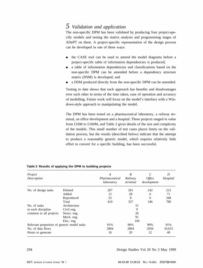
5 Validation and applicationThe non-specific DPM has been validated by producing four project-spe-cific models and testing the matrix analysis and programming stages ofADePT on them. A project-specific representation of the design processcan be developed in one of three ways:
I the CASE tool can be used to amend the model diagrams before aproject-specific table of information dependencies is produced;
I a table of information dependencies and classifications based on thenon-specific DPM can be amended before a dependency structurematrix (DSM) is developed; and
I a DSM produced directly from the non-specific DPM can be amended.
Testing to date shows that each approach has benefits and disadvantagesover each other in terms of the time taken, ease of operation and accuracyof modelling. Future work will focus on the model’s interface with a Win-dows-style approach to manipulating the model.
The DPM has been tested on a pharmaceutical laboratory, a railway ter-minal, an office development and a hospital. These projects ranged in valuefrom £16M to £160M, and Table 2 gives details of the size and complexityof the models. This small number of test cases places limits on the vali-dation process, but the results (described below) indicate that the attemptto produce a reasonably generic model, which requires relatively littleeffort to convert for a specific building, has been successful.
294 Design Studies Vol 20 No 3 May 1999
DST: design studies (page 16 ) 08-03-99 12:29:22 Rev 14.02x ZDST$$160H
Table 2 Results of applying the DPM to building projects
Project A B C DDescription Pharmaceutical Railway Office Hospital
laboratory terminal development
No. of design tasks Deleted 207 261 242 212Added 12 28 6 71Reproduced 23 8 0 348Total 410 357 346 789
No. of tasks Architecture 51in each discipline Civil eng. 9common to all projects Struct. eng. 26
Mech. eng. 91Elec. eng. 104
Relevant proportion of generic model tasks 91% 96% 99% 91%No. of data flows 2804 2804 2656 10,015Hours to generate 16 20 12 40
This testing of the DPM has meant that a broad range of design issues hasbeen included in the model validation to date. In formulating a project-specific model of the design process, the first task is in ensuring the modelcontent and structure is valid. The former requires the deletion of designactivities that are not relevant to the project, and the addition of activitiesassociated with specific features of the building not already covered. Theremay also be occasions where a section of the model must be duplicated,for example, where more than one type of ventilation system is to bedesigned, then the appropriate section of the model must be repeated. Thevalidity of the model was confirmed further by the largely repeatable natureof its structure, evident from the suitability of a high proportion of tasksto a diverse range of projects, as can be seen in Table 2. A limited numberof civil and structural tasks are applicable to each of the projects becauseof the different types of structure (foundations, ground floor slab, frame,etc.) designed in each project. Table 2 shows that despite this, relativelyfew additions were necessary to compile the model during its testing onthe three projects, as various choices for different structural systems areincluded in the non-specific model.
The second task in modelling a specific project was to review the infor-mation requirements of all design tasks. Again, this meant deleting (and,on occasions, adding or redirecting) information flows in the model.
6 ConclusionsThis paper has described a model of the detailed building design processthat is the first stage of the Analytical Design Planning Technique(ADePT). The model has been developed through the production of arevised IDEF0 process modelling notation termed IDEF0v, the implemen-tation of a three-point information classification system and the formulationof an information location matrix and deliverables definitions. The model,information classifications and information matrix have been verifiedacross two organisations and the model has been tested by successfullyrepresenting the design of four building projects. It has proved possible togenerate the project-specific models in an acceptable time scale. With time,the database of the DPM will grow, increasing its generic nature and reduc-ing the need for special project additions.
The design process model covers a wide range of building systems. Thismeans that the design activities and information dependencies in complexbuilding design problems can be represented and the ADePT planningmethodology can be used to programme and manage the design phase ofsuch projects. Practising designers and design managers shown the ADePTmethodology have been enthusiastic about the effectiveness of theapproach and the detailed nature of the DPM.
Analytical Design Planning Technique: a model of the detailed building design process 295
DST: design studies (page 17 ) 08-03-99 12:29:22 Rev 14.02x ZDST$$160H
21 RIBA Uniclass: unifiedclassification for the constructionindustry Royal Institute of BritishArchitects, RIBA Publications,London (1997)
Further work will examine the hierarchy of the DPM in relation to theUniclass system of structuring project information21, investigate therelationships between the detailed design stage (represented by the DPM)and other stages of the design process, study various means of formulatingproject-specific models and test the DPM and ADePT methodology onfurther building projects.
AcknowledgmentsThis work has been undertaken as part of a project entitled ‘Design Infor-mation Methodology and Tools for the Management of Detailed BuildingDesign’. The research is funded under research grant GR/K74197 by theEPSRC, DETR and industry (AMEC Design, Ove Arup and Partners,BAA, Boots, Laing Management and Sheppard Robson).
296 Design Studies Vol 20 No 3 May 1999
DST: design studies (page 18 ) 08-03-99 12:29:22 Rev 14.02x ZDST$$160H