analysis of thin shell structures prof. pieter sijpkes ... · thin shells cover medium to large...
TRANSCRIPT

page !1
ARCHITECTURAL STRUCTURES CHU CHEN 260564397
ARCH 241
!!
!!!!
Analysis of Thin Shell Structures
!Prof. Pieter Sijpkes
McGill University, School of Architecture
!!!!!!!!!!!!!!

page !2
Introduction
In this paper, I will investigate thin-shell concrete structures. First, I will describe general
characteristics of the structure with a focus on how the amazing spans are achieved. Second, I
will use three different examples to further explain the possibilities of the structure, focusing on
distinct features of each. Third, I will briefly discuss the application and development of thin-
shell concrete structures in the future.
There are two reasons why it would be interesting to research thin-shell concrete
structures. To begin with, they are structurally efficient and economically suitable and thus play a
substantial role in history. Thin-shell structures stemmed from the Modern Movement in
architecture which created an aesthetic impulse for buildings with dramatically long spans
unencumbered by columns (Thomas E. Boothby, 2012). In addition, the Modern Movement in
architecture idealized industrial architecture as expressive of the application of modern forms
and materials; it celebrated structural technology by exposing the materials and frameworks of
buildings (Thomas E. Boothby, 2012). Under such a circumstance, the thin-shell structures were
widely built throughout the entire world and became the International Style during the period
from 1920 to 1970 (Peerdeman, 2008). Furthermore, future revival of part of these structure is
likely. Contemporary architecture seems to experiment more with undefined free-form structures
(Peerdeman, 2008); one example is the EPFL Learning Center by SANAA (Peerdeman, 2008).
Historic thin-shell structures would be important examples to be consulted.
!Thin-Shell Structure
A thin shell structure is a structure composed of a curved slab whose thickness is small
compared to its other dimensions and compared with its principal radius of curvature
(Buyukozturk, 2004). Thin shells cover medium to large spans; a thin shell has a very small
thickness-to-minimal-radius ratio, often smaller than 1/50 (J. Blaauwendraad, 2014).
The major reason why shells are such strong and economic structures is that shells can
carry out-of-plane loads by in-plane membrane forces (J. Blaauwendraad, 2014). I will next
better explain this by comparing shell with plates. Both shells and plates are structures of which
the dimensions in two in-plane directions are large compared to the third direction perpendicular

page !3
to the plate. In other words, both cover a large span but has a comparatively negligible thickness.
Consequently, shells and plates are similar in that they are both defined by their middle plane,
thickness and material properties (J. Blaauwendraad, 2014), where the middle plane refers to the
plane parallel to surfaces of the plate or the shell that divides the thickness of the plane or the
shell into two halves (Eduard Ventsel, 2001), as is illustrated by Fig. 1 and Fig. 2. They are
different in that the middle plane of plates is flat whereas the middle plane in shells is curved (J.
Blaauwendraad, 2014). As a result, as for plates, in-plane loads generate in-plane membrane
forces, and out-of-plane loads generate moments and transverse shear forces (J. Blaauwendraad,
2014)). In contrast, as for shells, both out-of-plane and in-plane loads can be carried in shells by
in-plane membrane forces, which is not possible for plates (J. Blaauwendraad, 2014). This is
further illustrated by Fig. 3 in which the α- and β-coordinate lines are mutually perpendicular at
all points on a surface Ω (Eduard Ventsel, 2001). And such loads are uniformly distributed over
the shell thickness.
Fig. 1 Middle Plane of Plates Fig. 2 Middle Plane of Shells
Fig. 3 In-plane Membrane Force

page !4
There are two theories that explain the behavior of thin shell structures. The first theory is
called membrane theory. Membrane theory deals with the undisturbed and major part of the shell
which behaves like a true membrane, and such a state of stress is called membrane state of stress.
The main characteristic of this state of stress is that arbitrary external loading can be supported
by means of stress resultants (internal forces) and stress couples (bending and twisting moments)
(Eduard Ventsel, 2001). However, stress couples (bending and twisting moments) are either zero,
or so small that they may be neglected (Eduard Ventsel, 2001). This unique property of shells is a
result of the curvature of the spatial structure (J. Blaauwendraad, 2014). Owing to the shell
curvature, the projections of the direct forces on the normal to the middle surface develop an
Fig. 4 Elastic Foundation
Fig. 5 Cases in which Membrane Theory Fails

page !5
analog of an ‘elastic foundation’ under the shell (Eduard Ventsel, 2001). So, it can be said that a
shell resists an applied transverse loading as a flat plate resisting on an elastic foundation. This
phenomenon is explained in Fig. 4.
However, membrane theory is not sufficient to explain the behavior of thin shell
structures in all cases. For example, in Fig. 5, membrane theory is weak in expelling the
boundary conditions and deformation constraints, the case of concentrated loads, and the case
where the geometry of a shell is not perfectly continuous but suddenly changes at a line.
Therefore, the other theory is introduced which is called bending theory. Bending theory deals
with bending that is conned to boundaries; this is called edge disturbance in contrast to the
undisturbed membrane (J. Blaauwendraad, 2014). However, bending theory will not be discussed
in detail in this paper.
Conventional concrete mixture and high strength fibre reinforced concrete are two
potential materials for thin shell structures. Conventional concrete mixture refers to that
composed mainly of water, aggregate, and cement. For high strength fibre reinforced concrete,
silica fume, steel fibers, super plasticizers are added with different proportions; the concrete can
be further reinforced if fibers with different dimensions are added (Peerdeman, 2008). Thin shell
structure should be distinguished from arches in terms of the distribution of stresses; while an
arch of a given form will support only one completely determined load without bending, a shell
of a given shape has, provided its edges are suitable supported, as a rule, the same property of a
wide range of loads which satisfy only very general requirements (Eduard Ventsel, 2001). And
both compression and tension may exist within a thin shell structure. The structural behavior as
such cannot be realized without materials that have complicated nonlinear behaviors
(Peerdeman, 2008). Both conventional concrete mixture and fibre reinforced concrete are
feasible in this sense.
However, relatively, though conventional concrete shows high compressive strength, it
cannot resist much of tensile stress. Thus, high strength fibre reinforced concrete is preferable.
And there is empirical evidence that stresses in concrete shell constructed from (fibre) reinforced
concrete ‘are often a small proportion of those permitted by the strength of the material; and that

page !6
‘the foot of the shell is the only point where the stresses go above 50% of the allowable concrete
strength’ (Peerdeman, 2008).
I will not give detailed classifications of thin shell structure in this paper. I just show
some examples of different types of thin shell structure based on different geometries Fig. 6.
Among these, the most basic forms of thin shell structure are paraboloid of revolution and
hyperbolic paraboloid.
Lastly, I will discuss briefly another two important points about thin shell structure. First,
the main issue of thin-shell concrete structure is roofing. Shell geometries can be highly
Fig. 6 Classification of Thin Shell Structures
page !7
complex. There might be excessively steep and excessively flat or shallow roof slopes. This
makes it challenging to maintain a water tight roofing membrane and to address the potential for
concrete deterioration (Thomas E. Boothby, 2012).
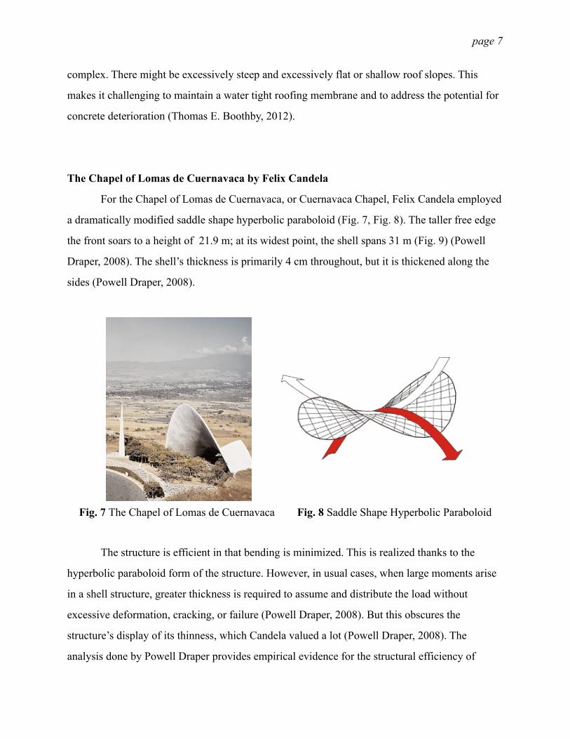
!!The Chapel of Lomas de Cuernavaca by Felix Candela
For the Chapel of Lomas de Cuernavaca, or Cuernavaca Chapel, Felix Candela employed
a dramatically modified saddle shape hyperbolic paraboloid (Fig. 7, Fig. 8). The taller free edge
the front soars to a height of 21.9 m; at its widest point, the shell spans 31 m (Fig. 9) (Powell
Draper, 2008). The shell’s thickness is primarily 4 cm throughout, but it is thickened along the
sides (Powell Draper, 2008).
The structure is efficient in that bending is minimized. This is realized thanks to the
hyperbolic paraboloid form of the structure. However, in usual cases, when large moments arise
in a shell structure, greater thickness is required to assume and distribute the load without
excessive deformation, cracking, or failure (Powell Draper, 2008). But this obscures the
structure’s display of its thinness, which Candela valued a lot (Powell Draper, 2008). The
analysis done by Powell Draper provides empirical evidence for the structural efficiency of
Fig. 7 The Chapel of Lomas de Cuernavaca Fig. 8 Saddle Shape Hyperbolic Paraboloid

page !8
shells. According to Draper (2008), principal shell stresses reach a maximum of 4,488 kPa in
compression and 1,131 kPa in tension. Both are well under the load-bearing limit of concrete. He
also mentions that maximum deformation in their finite-element analysis model was 0.5 cm; no
significant cracking was observed in the actual structure so they conclude that deformations are
kept within reasonable limits (Powell Draper, 2008).
One important aspect that contributes to the structural performance of shells is the
thickened edge. ‘At the chapel sides where the structure connects to the foundation, the shell
forces are concentrated, so Candela thickened it sufficiently to reduce the stress in the
Fig. 9 Dimensions of Cuernavaca Chapel (in ms)
Fig. 10 High Maximum Principal Stresses (Compression) and Increased Thickness

page !9
structure’ ("MAJOR WORKS, CHAPEL LOMAS DE CUERNAVACA," 2008). Fig. 10 and Fig.
11 show how this is done in the actual structure. According to Draper (2008), edge beam with
varying thickness and an edge beam, as the actual structure has, is the most efficient structure
compared shells of uniform thickness and shells of uniform thickness but with edge beam. The
finite-element model results for the comparison is shown in Table 1. It is clear from the table that
a structure with varying thickness shows a general reduction of stress from the models with
uniform thickness and a more gradual distribution of stress throughout the shell (Powell Draper,
2008). Meaning, bending is better minimized.
Another important merit of Felix Candela’s Chapel of lomas de Cuernavaca is the
connection between its form and its function. It is clear from previous analysis that nothing was
done for purely aesthetic effect; the choice of form was inextricably connected to its structural
purpose ("MAJOR WORKS, CHAPEL LOMAS DE CUERNAVACA," 2008). However, this
basic structural form of the hyperbolic paraboloid does not bind the designer into a
predetermined geometry (Powell Draper, 2008). Within the discipline of the hyperbolic
paraboloid, Candela found room for creative design, by maximizing the effect of the free edge
with a strikingly tall opening. It is true that such modification to the basic structural from creates
the issue of increased dead load and wind load; Candela countered by adeptly thickening the
Fig. 11 High Maximum Principal Stresses (Tension) and Increased Thickness

page !10
edges and back of the structure. The result is that the structure adheres to an efficient geometrical
form, but it can also be viewed as a piece of art.
!The TWA Flight Center at New York’s JFK Airport by Eero Saarinen
The exterior of the TWA terminal is composed of remarkably few elements, and its
simplicity is furthered by the two building materials: concrete buttresses and green-tinted glass
walls (Commission, 1994). The wing-like roof of the central portion rises above low wings that
extend on the east and west, and follow the curve of the airport service road. Extending from the
main terminal are two raised walkways that connect with gate structures on the aircraft ramp; the
two-story eastern gate structure has a pair of remote gate lounges. The exterior concrete area of
terminal are painted in a range of cream shades. Four complexly-massed piers support the roof
over the central portion of the terminal. The four segments of the roof, separated by narrow
skylights, meet at the central roof plate. They enclose the terminal and are described as four
lobes or segmental domes, each of which stands alone, resting on two buttress supports as is
illustrated in Fig. 12 and Fig. 13 (Commission, 1994). They are also outwardly-canting,
extending as far as eighty feet. Fig. 14, the construction of the TWA Flight Center better shows
how the roof rests on the buttress supports.
Fig. 12 TWA Flight Center Structure 1

page !11
!!!
Fig. 13 TWA Flight Center Structure 2
Fig. 14 Construction of TWA Flight Center

page !12
The Miami Marine Stadium by Hilario Candela (Fig. 15)
I will start by giving general descriptions of the cast-in-place folded thin shell reinforced
concrete roof. The roof consists of eight thin shell structural units. Each unit comprises of four
hyperbolic paraboloid shells monolithically joined together along a centerline to form a V-shaped
cross-section, as is illustrated in Fig. 16 (Sigrid Adriaenssens, 2014). The V-shaped unit is
supported by three inclined columns—two at the back and one at the interior. The unit
cantilevers 20.2 m forward from the interior column over the stands below towards the water
(Sigrid Adriaenssens, 2014). The folds are joined together via a keyed joint filled with concrete
grout which also contain steel weld tabs that prevent relative translation between adjacent folds
(Sigrid Adriaenssens, 2014). The Miami Marine Stadium is unique in that no other realized
concrete structure has a series of cantilevering hypar units monolithically attached and linearly
placed next to each other, and such a system of attached units leads to better structural
performance (smaller bending moments and increased stiffness) compared to a system of
individual units (Sigrid Adriaenssens, 2014). The roof structure region between the back and
interior columns is referred to as the backspan and the overhang is referred to as the cantilever as
illustrated in Fig. 17. On top of the roof, the backspan and cantilever are separated by a concrete
beam, referred to as the stiffener. The stiffener is located above the line that connects the tops of
the interior columns.
Fig. 15 The Miami Marine Stadium by Hilario Candela

page !13
I will next give specific analysis for the hyperbolic paraboloid shell roof. Hyperbolic
parabolic shells can be visualized as two systems of arches, one downward curving parabola in
compression and one upward curving parabola in tension (Fig. 16) (Sigrid Adriaenssens, 2014).
Fig. 18 better illustrates the difference between two arches. The arch forces are brought to the
straight line edges (or edge beams and groin folds in the case of the Miami Marine Stadium)
where the components perpendicular to these edges cancel and the components parallel to the
edges add to give shear forces along the edge beams and fold groins (Sigrid Adriaenssens, 2014).
The edge beams and fold groins in turn carry the shear forces by axial tension or compression. In
the Miami Marine Stadium shells the lower groin folds carry compression forces to the interior
and back columns while the higher groin folds and exterior edge beams carry tension (Sigrid
Adriaenssens, 2014).
What I find special about this building is Hilario Candela’s concern about the materiality
of buildings. As discussed previously, concrete is one of the ideal materials for thin shell
Fig. 16 Folded Thin Shell Roof
Fig. 17 Roof Structure

page !14
structures, and in the Miami Marine Stadium, such a decision out of structural requirement and
economic functionality also serve aesthetic purposes. According to Candela, who is in love with
Dulles Airport at Washington, DC (Fig. 19), ‘[Saarinen] placed the roof on top like canopy.
Every column is gorgeous. The way the form of those columns gets to the ground and human
beings can touch the concrete and feel it and be next to it… This is exactly what I was
after’ (Sigrid Adriaenssens, 2014). Hence, he further developed and maximized the ‘softness and
strength’ of concrete in the Miami Marine Stadium.
!!!!!
Fig. 18 The Downward Curving Parabola and the Upward Curving Parabola
Fig. 19 The Interior of Dulles Airport at Washington, DC

page !15
Conclusion and Future Development
Given previous analysis of thin shell structures in general and analysis of Cuernavaca
Chapel, TWA Flight Center, and Miami Marine Stadium, I will give a conclusion as follow. First,
Concrete shells are efficient structures and can be used as durable solutions for roofs or for
covering large spaces. Second, concrete shells can be built with limited thicknesses, and
necessity for interior columns is reduced, thus maximizing the space inside them (Aurelio
Muttoni, 2013). However, for the thin shell structure to be widely applied in contemporary
buildings, a more efficient construction technique has to be developed. According to the statistics
of a concrete shell covering a mall at Chiasso, Switzerland, the cost of the concrete structure
was: “49 % for falsework and formwork, 21 % for ordinary reinforcement, 5 % for post-
tensioning, 24 % for sprayed concrete and 1 % for poured in situ concrete. (Aurelio Muttoni,
2013)” This reveals the relatively large cost of false work and formwork for this type of
structure, and points to the need for future research on more efficient construction techniques.
!!!!!!!!!!!!!!!

page !16
Bibliography
Aurelio Muttoni, F. L., Miguel Fernández Ruiz. (2013). Concrete shells – towards efficient structures: construction of an ellipsoidal concrete shell in Switzerland. Structural Concrete, 14(1), 43-50. doi: 10.1002/suco.201200058
Buyukozturk, O. (2004). Mechanics and Design of Concrete Structures, Reinforced Concrete Thin Shell Structures. http://ocw.mit.edu/courses/civil-and-environmental-engineering/1-054-mechanics-and-design-of-concrete-structures-spring-2004/lecture-notes/o_12_rc_th_sh_st.pdf
Commission, L. P. (1994). TRANS WORLD AIRLINES FLIGHT CENTER (now TWA Terminal A) AT NEW YORK INTERNATIONAL AIRPORT. Retrieved from http://www.npclibrary.org/db/bb_files/Trans-World-Airlines-Flight-Centre.pdf.
Eduard Ventsel, T. K. (2001). Thin Plates and Shells Theory, Analysis, and Applications
J. Blaauwendraad, J. H. H. (2014). Structural Shell Analysis Understanding and Application doi:10.1007/978-94-007-6701-0
MAJOR WORKS, CHAPEL LOMAS DE CUERNAVACA. (2008). from http://mcis2.princeton.edu/candela/cuernavaca.html
Peerdeman, B. (2008). Analysis of Thin Concrete Shells Revisited: Opportunities due to Innovations in Materials and Analysis Methods. (Master), Delft University of Technology.
Powell Draper, M. E. M. G., David P. Billington. (2008). Finite-Element Analysis of Felix Candela’s Chapel of Lomas de Cuernavaca. Journal of Architectural Engineering, 14(2). doi: 10.1061/(ASCE)1076-0431(2008)14:2(47)
Sigrid Adriaenssens, N. B., Rosa Lowinger & Jorge Hernandez. (2014). Structural Analysis of Reinforced Concrete Folded Hyperbolic Paraboloid: A Case Study of the Modern Miami Marine Stadium. International Journal of Architectural Heritage: Conservation, Analysis, and Restoration, 8(4), 498-516. doi: 10.1080/15583058.2012.694967
Thomas E. Boothby, M. K. P., Mark Ketchum. (2012). Milo S. Ketchum and Thin-Shell Concrete Structures in Colorado. APT Bulletin: Journal of Preservation Technology, 43(1), 39-46.