analysis of the response under live loads of two new cable
TRANSCRIPT

17
Analysis of the Response Under Live Loads of Two New Cable Stayed Bridges Built in Mexico
Roberto Gómez, Raul Sánchez-García, J.A. Escobar and Luis M. Arenas-García
© Springer International Publishing Switzerland 2016 A. Caner et al. (eds.), Developments in International Bridge Engineering, Springer Tracts on Transportation and Traffic 9, DOI 10.1007/978-3-319-19785-2_2
Abstract In this paper we study the response, under live loads, of two new cable stayed bridges (Baluarte and Carrizo), recently open to traffic. Both bridges are located in the northern pacific mountains of Mexico along the Mazatlan-Durango new highway at approximately 50 km from the coast. These bridges happen to be the most important bridge structures of the highway. Both bridges have the same fan cable pattern and similar type of superstructure. However the response of both decks under live loads is quite different as will be shown. This paper describes also the numerical analyses to evaluate the bridges structural response under static and moving loads mainly. From this evaluation and assessment, conclusions and recommendations related to their structural stability are provided. The activi-ties described were performed before opening the bridges and comprised also the instrumentation with fiber optic sensors, live load tests and ambient vibration tests.
Keywords Vehicular loads · Cable-Stayed bridge · Load testing · Analytical response bridge
1 Introduction
Built to cross the Pacific mountains of Mexico (Western Sierra Madre) a new highway was open to traffic last year. The highway has a total length of 230 km and 12 m wide to accommodate 2 lanes. However, from 156 + 300 km to 164 + 000 km the highway has four lanes. Along the highway 63 tunnels and 115 bridges were built. Among the structures of greater importance in this road are, in
R. Gómez (*) · R. Sánchez-García · J.A. Escobar · L.M. Arenas-García Institute of Engineering, National Autonomous University of Mexico, Ciudad Universitaria, Coyoacán, Mexico City, Mexicoe-mail: [email protected]
18 R. Gómez et al.
first place, the “Baluarte” cable stayed bridge with a length of 1124 m and a height of 402 m, second, the “Sinaloense” tunnel with 2.78 km length and, third, another cable stayed bridge, the “Carrizo”, at 162 + 172 km.
Since the beginning of the construction of the highway, the Ministry of Communications and Transport of Mexico (SCT) commended, among other tasks, to the Institute of Engineering of UNAM (IIUNAM), the instrumentation and monitoring of both bridges in different important aspects and stages of their con-struction. These activities developed by IIUNAM during the construction of the bridges can be summarized in the following major tasks: monitoring of displace-ments of rock stratums; tilts and stresses in pylon 5; wind velocities; topography; and instrumentation and load tests of the main span.
In this paper we only describe results of field tests under static loads carried out in the main section of the superstructures. This information was useful to calibrate the mathematical models, as well as to confirm the recommendations of the wind and seismic design studies developed previously to the design stage of the bridge.
In another section of the paper, we present results of the analyses of the bridges under moving loads representing design live loads used in Mexico. Implications of the results in the structural behavior of the bridges are presented in the conclusions.
2 The Bridges
2.1 The “Baluarte” Bridge
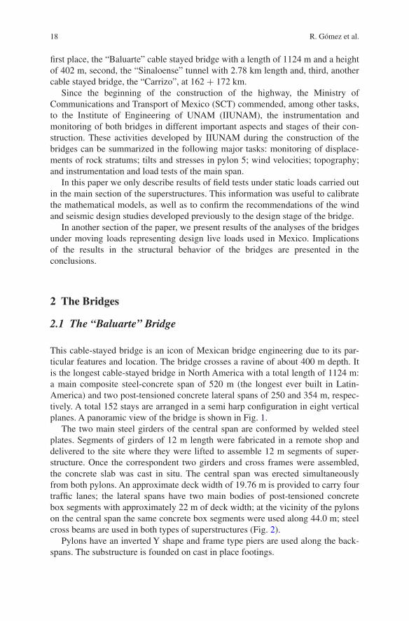
This cable-stayed bridge is an icon of Mexican bridge engineering due to its par-ticular features and location. The bridge crosses a ravine of about 400 m depth. It is the longest cable-stayed bridge in North America with a total length of 1124 m: a main composite steel-concrete span of 520 m (the longest ever built in Latin-America) and two post-tensioned concrete lateral spans of 250 and 354 m, respec-tively. A total 152 stays are arranged in a semi harp configuration in eight vertical planes. A panoramic view of the bridge is shown in Fig. 1.
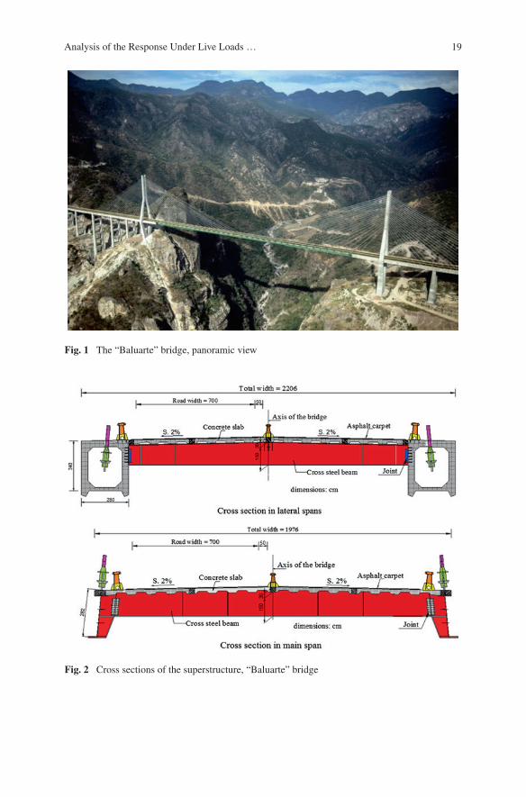
The two main steel girders of the central span are conformed by welded steel plates. Segments of girders of 12 m length were fabricated in a remote shop and delivered to the site where they were lifted to assemble 12 m segments of super-structure. Once the correspondent two girders and cross frames were assembled, the concrete slab was cast in situ. The central span was erected simultaneously from both pylons. An approximate deck width of 19.76 m is provided to carry four traffic lanes; the lateral spans have two main bodies of post-tensioned concrete box segments with approximately 22 m of deck width; at the vicinity of the pylons on the central span the same concrete box segments were used along 44.0 m; steel cross beams are used in both types of superstructures (Fig. 2).
Pylons have an inverted Y shape and frame type piers are used along the back-spans. The substructure is founded on cast in place footings.
19Analysis of the Response Under Live Loads …
Fig. 1 The “Baluarte” bridge, panoramic view
Fig. 2 Cross sections of the superstructure, “Baluarte” bridge
20 R. Gómez et al.
2.2 The “Carrizo” Bridge
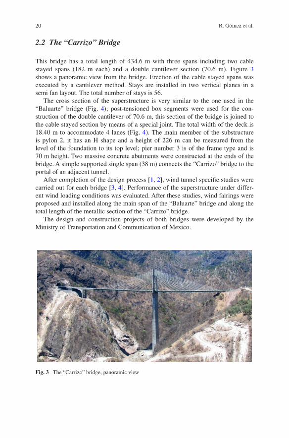
This bridge has a total length of 434.6 m with three spans including two cable stayed spans (182 m each) and a double cantilever section (70.6 m). Figure 3 shows a panoramic view from the bridge. Erection of the cable stayed spans was executed by a cantilever method. Stays are installed in two vertical planes in a semi fan layout. The total number of stays is 56.
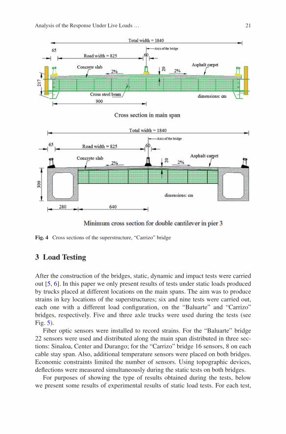
The cross section of the superstructure is very similar to the one used in the “Baluarte” bridge (Fig. 4); post-tensioned box segments were used for the con-struction of the double cantilever of 70.6 m, this section of the bridge is joined to the cable stayed section by means of a special joint. The total width of the deck is 18.40 m to accommodate 4 lanes (Fig. 4). The main member of the substructure is pylon 2, it has an H shape and a height of 226 m can be measured from the level of the foundation to its top level; pier number 3 is of the frame type and is 70 m height. Two massive concrete abutments were constructed at the ends of the bridge. A simple supported single span (38 m) connects the “Carrizo” bridge to the portal of an adjacent tunnel.
After completion of the design process [1, 2], wind tunnel specific studies were carried out for each bridge [3, 4]. Performance of the superstructure under differ-ent wind loading conditions was evaluated. After these studies, wind fairings were proposed and installed along the main span of the “Baluarte” bridge and along the total length of the metallic section of the “Carrizo” bridge.
The design and construction projects of both bridges were developed by the Ministry of Transportation and Communication of Mexico.
Fig. 3 The “Carrizo” bridge, panoramic view
21Analysis of the Response Under Live Loads …
3 Load Testing
After the construction of the bridges, static, dynamic and impact tests were carried out [5, 6]. In this paper we only present results of tests under static loads produced by trucks placed at different locations on the main spans. The aim was to produce strains in key locations of the superstructures; six and nine tests were carried out, each one with a different load configuration, on the “Baluarte” and “Carrizo” bridges, respectively. Five and three axle trucks were used during the tests (see Fig. 5).
Fiber optic sensors were installed to record strains. For the “Baluarte” bridge 22 sensors were used and distributed along the main span distributed in three sec-tions: Sinaloa, Center and Durango; for the “Carrizo” bridge 16 sensors, 8 on each cable stay span. Also, additional temperature sensors were placed on both bridges. Economic constraints limited the number of sensors. Using topographic devices, deflections were measured simultaneously during the static tests on both bridges.
For purposes of showing the type of results obtained during the tests, below we present some results of experimental results of static load tests. For each test,
Fig. 4 Cross sections of the superstructure, “Carrizo” bridge

22 R. Gómez et al.
the trucks configuration is presented together with a graph showing the obtained stresses considering a structural steel A572 gr50. These graphs only show the results for the sensors at the center of the main spans. The Fig. 6 shows the con-figuration of trucks on the deck and the corresponding measurements of a specific test performed at the “Baluarte” bridge; sensors A5, A6 and A7 were placed at the center of the mains span. Figure 7 shows another test carried out at the “Carrizo” bridge; in this case sensors S5, S6, S7 and S8 were placed at segments twelve and thirteen, side Sinaloa. All of these sensors were located at the bottom flange of the girders.
Fig. 5 Type of trucks used for field tests
Fig. 6 Static load test “E2”, “Baluarte” bridge
Fig. 7 Static load test “E9”, “Carrizo” bridge
23Analysis of the Response Under Live Loads …
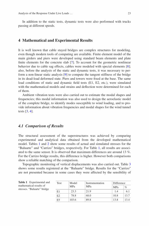
In addition to the static tests, dynamic tests were also performed with trucks passing at different speeds.
4 Mathematical and Experimental Results
It is well known that cable stayed bridges are complex structures for modeling, even though modern tools of computing are available. Finite element model of the main girders and piers were developed using standard beam elements and plate finite elements for the concrete slab [7]. To account for the geometric nonlinear behavior due to cable sag effects, cables were modeled with special elements [8]; also, before the analysis of the static and dynamic tests, it was necessary to per-form a non-linear static analysis [9] to compute the tangent stiffness of the bridge in its dead-load deformed state. Piers and towers were fixed at the base. The same load conditions of static and dynamic field tests (E1, E2, etc.), were simulated with the mathematical models and strains and deflection were determined for each of them.
Ambient vibration tests were also carried out to estimate the modal shapes and frequencies; this modal information was also used to design the aeroelastic model of the complete bridge, to identify modes susceptible to wind loading, and to pro-vide information about vibration frequencies and modal shapes for the wind tunnel tests [3, 4].
4.1 Comparison of Results
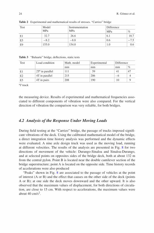
The structural assessment of the superstructures was achieved by comparing experimental and analytical data obtained from the developed mathematical model. Tables 1 and 2 show some results of actual and simulated stresses for the “Baluarte” and “Carrizo” bridges, respectively. For Table 1, all results are associ-ated to the same sensor. It is observed that maximum differences are around 13 %. For the Carrizo bridge results, this difference is higher. However both comparisons show a reliable matching of the comparison.
Topographic monitoring of vertical displacements was also carried out. Table 3 shows some results registered at the “Baluarte” bridge. Results for the “Carrizo” are not presented because in some cases they were affected by the sensibility of
Table 1 Experimental and mathematical results of stresses. “Baluarte” bridge
Test ModelMPa
InstrumentationMPa
Difference
MPa %
E1 23.3 21.9 1.4 6.1
E2 78.8 68.0 10.8 13.7
E5 103.6 89.8 13.8 13.4
24 R. Gómez et al.
the measuring device. Results of experimental and mathematical frequencies asso-ciated to different components of vibration were also compared. For the vertical direction of vibration the comparison was very reliable, for both bridges.
4.2 Analysis of the Response Under Moving Loads
During field testing at the “Carrizo” bridge, the passage of trucks imposed signifi-cant vibrations of the deck. Using the calibrated mathematical model of the bridge, a direct integration time history analysis was performed and the dynamic effects were evaluated. A nine axle design truck was used as the moving load, running at different velocities. The results of the analysis are presented in Fig. 8 for two directions of movement of the vehicle: Durango-Sinaloa and Sinaloa-Durango, and at selected points on opposites sides of the bridge deck, both at about 132 m from the central pylon. Point B is located near the double cantilever section of the bridge superstructure; point A is located on the opposite side. Time history records of accelerations were also produced
“Peaks” shown in Fig. 8 are associated to the passage of vehicles at the point of interest (A or B) and the effect that causes on the other side of the deck (points A or B); at one side the deck moves downward and the other upward. It is also observed that the maximum values of displacement, for both directions of circula-tion, are close to 15 cm. With respect to accelerations, the maximum values were about 40 cm/s2.
Table 2 Experimental and mathematical results of stresses. “Carrizo” bridge
Test ModelMPa
InstrumentationMPa
Difference
MPa %
E1 32.7 26.6 6.1 18.7
E5 −8.2 −8.8 0.6 −7.5
E9 155.0 154.0 1.0 0.6
Table 3 “Baluarte” bridge, deflections, static tests
aT truck
Test Load condition Math. model Experimental Difference
mm mm mm %
E1 2Ta in parallel 111 59 41 47
E2 4T in parallel 215 206 −6 4
E5 4T in pairs 208 190 10 9

25Analysis of the Response Under Live Loads …
5 Conclusions
Modelling, analysis and experimental testing of two cable stayed bridges were presented. Measured deflections at the “Baluarte” bridge are comparable with the results of the mathematical model. Maximum stresses produced by live loads are about 90 MPa, and when added to dead load stresses the results are below design or allowable stresses. For the “Carrizo” bridge, stresses produced by live loads, similar to design loads, are higher, about 156 MPa, which represents 74.2 % of the allowable stress. In this case, when this level of stresses is considered together with dead loads, some sections of the structure fail to comply, by a minimum amount, with allowable design stresses.
Although both superstructures showed a very good elastic recovery capac-ity, from the point of view of displacements and vibrations the “Carrizo” bridge superstructure is more flexible compared to the “Baluarte” bridge. In general, both superstructures showed a good performance.
The calibrated mathematical models and the instrumentation will be used for a permanent monitoring of the behavior of the superstructures under regular traffic.
Fig. 8 Time histories of displacements, “Carrizo” bridge. a Direction Sinaloa. b Direction Durango
26 R. Gómez et al.
Acknowledgments The Ministry of Communication and Transportation of Mexico provided the funds for the development of the work carried out by IIUNAM staff.
References
1. Ministry of Communication and Transport of Mexico (2008) Executive project of “Baluarte” bridge. Mexico
2. Ministry of Communication and Transport of Mexico (2011). Executive project of “Carrizo” bridge. Mexico
3. Gómez R, Pozos A (2010) Report on the wind tunnel testing at UWO of an aeroelastic model of the “Baluarte” bridge (in Spanish). Technical report presented to the Ministry of Communication and Transport of Mexico. Institute of Engineering, UNAM, Mexico
4. Gómez R, Pozos A (2012) Report on the wind tunnel testing at UWO of an aeroelastic model of the “Carrizo” bridge (in Spanish). Technical report, presented to the Ministry of Communication and Transport of Mexico. Institute of Engineering, UNAM, Mexico
5. Gómez R, Arenas LM, Sanchez R, Escobar JA, Paredes CA, Rosales ON (2013) Static and dynamic load testing of the main span of the “Baluarte” cable stayed bridge (in Spanish). Technical report, presented to the Ministry of Communication and Transport of Mexico. Institute of Engineering, UNAM, Mexico
6. Gómez R, Arenas LM, Sanchez R, Escobar JA, Paredes CA, Rosales ON (2013) Static and dynamic load testing of the main span of the “Carrizo” cable stayed bridge (in Spanish). Technical report presented to the Ministry of Communication and Transport of Mexico, Institute of Engineering, UNAM, Mexico
7. SAP2000 (2009) V. 14.0. Integrated finite element analysis and design of structures. Computers and structures, Berkeley, CA
8. Gimsing NJ (1983) Cable supported bridges, concept and design. Wiley, New York9. Nazmy AS, Abdel-Ghaffar AM (1992) Effects of ground motion spatial variability on the
response of cable-stayed bridges. Earthq Eng Struct Dynam 21:1–20

http://www.springer.com/978-3-319-19784-5