analysis of the nb-iot technology towards massive machine
TRANSCRIPT

1
Analysis of the NB-IoT technology towards
massive Machine Type Communication
Developed in Facoltà di Ingegneria dell’Informazione, Informatica e
Statistica, Università Sapienza di Roma,
a bachelor thesis submitted to the Faculty of Barcelona School of
Telecommunications Engineering (ETSETB) by Pol Serra i Lidón, in partial
fulfilment of the requirements for the
Degree in Telecommunication Technologies and Services
Engineering
Project Supervisor Project Author
Maria-Gabriella di Benedetto Pol Serra i Lidón
Co-Supervisors
Giuseppe Caso
Anna Umbert Juliana
Academic Year 2017/2018

2
Acknowledgements
I would like to express my gratitude to my supervisor in University Sapienza di Roma, Prof.
Maria-Gabriella di Benedetto, who gave me the opportunity to realize my thesis in the
Department of Information Engineering, Electronics and Telecommunication, and for her
interest and advise.
Besides, I would like to thank the rest of the Department members. Especially, to my thesis
co-supervisor, Dr. Giuseppe Caso, for his guidance and advise during the development of
the thesis.
Furthermore, I am grateful with my friends in Rome for sharing with me this semester and
making this a nice experience.
Finally, I want to thank all my family, that have been supporting and encouraging me to
always go forward.

3
Abstract
The Internet of Things (IoT) is going to redefine the way people interact with each other and
with the objects that surround them, with the goal of creating a global network connecting
everyone, and everything. IoT is expected to accommodate massive Machine Type
Communication (mMTC), in which devices transmit and receive a small amount of data,
with the goal of improving industrial and metering processes, health services, and
transportation, to mention a few.
Low Power Wide Area (LPWA) radio technologies have emerged as a solution for the design
of mMTC, satisfying the requirements of low power consumption, low data rates, scalability,
and long range. Narrow Band (NB) approaches are being analyzed by research and
standardization communities, and some candidates for the creation of LPWA networks have
been proposed and deployed, towards a satisfying balance between the challenge of
accommodating many devices and the optimal exploitation of the limited spectrum
resources.
3GPP introduced in 2016 (Release 13), the Narrowband Internet of Things (NB-IoT), as a
brand new cellular technology, thus going to be a step forward 5G based IoT
implementation. NB-IoT is compatible with 4G Long Term Evolution system (LTE), and
with 2G Global Systems for Mobile communication (GSM). This advantage, added to a
higher spectral efficient usage, places the technology in a privileged position for the
implementation of LPWA networks.
Late 2017 and 2018 will be the initial period where operators like Vodafone, Huawei, T-
Mobile along with Qualcomm, Ericsson, Deutsche Telecom, or Telecom Italia, among others,
will deploy their NB-IoT architectures on a country basis.
The aim of this work is to analyze the deployment of NB-IoT technology in a dense urban
scenario, and the performance enhancement of NB-IoT devices thanks to signal repetition
procedures. Furthermore, a preliminary analysis of an heterogenous architecture is
presented, that embeds the traditional cellular outdoor architecture formed by macrocells,
with indoor small cells, with the goal of increasing the overall system coverage.
4
Table of Contents
1. Introduction .............................................................................................. 7
1.1 Internet of Things .................................................................................................... 7
1.2 Machine Type Communications ........................................................................... 8
1.2.1 Scalability ............................................................................................................ 9
1.2.2 Heterogeneity .................................................................................................... 10
1.2.3 System Requirements ........................................................................................ 10
1.2.4 Architecture ....................................................................................................... 10
1.2.4.1 Device and Gateway ................................................................................... 10
1.2.4.2 Network and Application Domain ............................................................. 11
1.3 Smart Environments ............................................................................................. 13
2. Enabling technologies for the IoT ..................................................... 16
2.1 Low Power Wide Area Networks ...................................................................... 16
2.1.1 Standardization Efforts on LPWAN ................................................................. 16
2.1.2 Main Challenges................................................................................................ 17
2.2 LPWAN on Unlicensed Spectrum ...................................................................... 18
2.2.1 SIGFOX ............................................................................................................ 18
2.2.2 LoRa................................................................................................................... 18
2.2.3 Weightless ......................................................................................................... 19
2.2.4 Unlicensed Spectrum Considerations ............................................................... 19
2.3 LPWAN on Licensed Spectrum .......................................................................... 19
2.3.1 LTE-M ............................................................................................................... 19
2.3.2 Narrowband IoT ................................................................................................ 20
2.4 Technologies Comparison ................................................................................... 20
3. NB-IoT ..................................................................................................... 23
3.1 Primer on LTE ....................................................................................................... 23
3.1.1 Frequency and Modulations ............................................................................. 24
3.1.2 Network Architecture ........................................................................................ 24
3.1.3 Protocol Stack .................................................................................................... 26
3.1.4 Channels Overview ........................................................................................... 27
3.1.5 Physical Layer ................................................................................................... 28
3.1.5.1 Downlink: OFDMA Modulation and Frame Structure ............................ 28
3.1.5.2 Uplink: SC-FDMA Modulation ............................................................... 29
3.1.5.3 Uplink Physical Channels and Signals ..................................................... 30
3.1.6 Attachment Procedure and Random Access ..................................................... 31

5
3.1.7 Additional Features ........................................................................................... 32
3.2 From LTE to LTE-Advanced ............................................................................... 33
3.3 NB-IoT Technology .............................................................................................. 33
3.3.1 Operation Modes ............................................................................................... 34
3.3.2 Physical Layer ................................................................................................... 35
3.3.3 Physical Channels and Signals ......................................................................... 36
3.3.4 Signal Repetitions ............................................................................................. 38
3.3.5 Deployment Considerations .............................................................................. 38
3.3.5.1 LTE Coexistence ......................................................................................... 38
3.3.5.2 Synchronization ........................................................................................ 39
3.3.5.3 Device Complexity .................................................................................... 39
3.3.6 Main Differences between NB-IoT and LTE .................................................... 40
3.3.6.1 Physical Layer ............................................................................................ 40
3.3.6.2 Full Duplex (Uplink vs. Downlink)........................................................... 40
4. Network Simulator-3 ............................................................................ 41
4.1 Simulation Modules ............................................................................................. 41
4.2 Propagation channel models ............................................................................... 43
4.2.1 Outdoor: ITU R1411 NLoS Over Rooftop ...................................................... 43
4.2.2 Indoor: ITU InH .............................................................................................. 43
4.3 Simulation Parameters for NB-IoT ..................................................................... 44
4.3 Base Station Types and Attachment................................................................... 44
4.3.1 Indoor Base Station ........................................................................................... 44
4.3.2 Outdoor Base Station ........................................................................................ 45
4.3.3 Attachment Procedure ...................................................................................... 46
5. Use cases and results ............................................................................. 47
5.1 Use Cases ............................................................................................................... 48
5.1.1 Tri-sectorial Antenna ........................................................................................ 48
5.1.2 Dense City Scenario .......................................................................................... 49
5.1.3 Heterogenous Scenario ...................................................................................... 50
5.2 Results .................................................................................................................... 52
5.2.1 Tri-sectorial Antenna ........................................................................................ 52
5.2.2 Dense City Scenario .......................................................................................... 53
5.2.2.1 Selection of repeating UEs by distance ...................................................... 53
5.2.2.2 Selection of repeating UEs by performance ................................................ 54
5.2.3 NB-IoT with heterogenous architecture ............................................................ 56
5.2.3.1 Small Cell Aggregation to a Tri-sectorial Antenna ................................... 57
5.2.3.2 Small Cell Aggregation to a Dense City Scenario .................................... 57

6
5. Conclusions and Future Works ........................................................... 59
Budget ...................................................................................................... 60
References ............................................................................................... 61
List of Abbreviations ............................................................................ 64
List of Tables .......................................................................................... 68
List of Figures ......................................................................................... 68

7
1 Introduction
1.1 Internet of Things
The Internet of Things (IoT) is a network composed by the interconnection of a plethora of
elements.
One decade after the concept was firstly coined in 1999 by Kevin Ashton [1], a fast-paced
technological development of multiple platforms, standards, applications and devices has
turned the IoT into a world-renowned system. Due to the introduction of smart mobiles and
tablets, among others, humans can constantly stay connected to the Internet in their daily
lives. In fact, it is expected that the number of connected devices will grow constantly in the
next decade [2], with tens of billions of connected devices by then [3]. From that perspective,
it is practically impossible to avoid being part of the hyperconnected network that
represents the Internet.
Thanks to the usage of embedded sensors, devices can extract information regarding the
physical world and share different types of data. Data is processed, and then it can be used
in several applications. IoT is expected to evolve and develop in many directions the next 5-
10 years, and as the IoT involves lots of different knowledge and fields, many
standardization bodies, companies, and researchers must work together to carry on this
pharaonic system. Besides the new and fruitful opportunities around the IoT that will arise,
the final aim of this technology is to improve human’s life quality with practical
applications. Thus, IoT can be used in different fields such as metering, health, transport,
surveillance or industry, magnifying its impact on every part of the society.
Attached devices will grow in number during the next years, and others than common
computers and smartphones will join, creating a more complex system of interconnected
nodes. Also, the IoT network requires of some segmentation. Some parts of the network,
will inevitably need different levels of security, data rates, or communication techniques.
Consequently, scalability and heterogeneity are two key technological problems to address
when facing the construction of the future IoT network.
Machines oversee obtaining, transmitting, and analyzing data without almost any human
intervention, so IoT cannot be able to prosper without Machine Type Communications
(MTC). More specifically, some applications and scenarios are ruled directly by machines
capable to communicate and share knowledge between their peers. As stated above, IoT can
be useful in many different scenarios, and they can be distinguished and classified by
different characteristics.

8
A general taxonomy can be traced studying different types of smart environments and its
different characteristics. We can classify cases by their communication enablers, network
types, local area wireless standards, and so on. The most widespread technologies to
provide communication across the Internet are Wi-Fi, GSM (3G), and LTE (4G), as reported
in Table 1.1-1.
Technology Frequency Data rates Range Power
Consume
Application
Bluetooth 2,4 GHz 25 Mb/s 10 m Low Smart home
DASH7 433 MHz
(Europe)
55 kb/s,
200kb/s
1000m Low Smart cities,
buildings, transport,
health
ZigBee 868, 915, 2400
MHz
250 kb/s Up to 100m Low Smart homes, health
Wi-Fi 2.4 GHz, 5
GHz
54 Mb/s, 6.75
Gb/s
140 m, 100 m Medium Smart cities, home,
buildings, transport,
industry, grid
3G 750 MHz 24.8 Mb/s 1-5 mi High Smart cities,
transport, industry,
grid
4G 700, 750, 800,
1900, 2500
MHz
800 Mb/s 1-6 mi High Smart cities,
transport, industry,
grid
Table 1.1-1 Main technologies involved in IoT
1.2 Machine Type Communications
Inside the IoT ecosystem, we found the MTC, also Machine to Machine Communications
(M2M), that refers to the data generation, exchange, and actuation between interconnected
machines, where end-to-end device communication is achieved with low or any human
intervention. The topic involves mobile network operators, MTC companies, researchers,
and standardization bodies. The major challenges in MTC are: scalable deployment,
protocol flexibility, energy efficiency, and compatibility with actual cellular technologies
and future 5G mobile communication networks.
In the device domain, an MTC system is mostly managed remotely and acts automatically.
The monitoring and actuator devices can be mobile or fixed, and scalable up to an order of

9
1012. After the data acquisition and exchange, the system processes and interprets the data.
The main institutions working on MTC are 3GPP and IEEE on the wireless access side, while
ETSI on the architecture and components counterpart.
Inside MTC, it should be distinguished the massive MTC and the critical MTC, whose main
characteristics are listed in Table 1.2-1.
Massive MTC Critical MTC
Massive number of devices Very reliable
Low device cost Very low latency
Long battery life High availability
Small data volumes per device Short transmission times
Scalable and flexible access Contention-based access
Pervasive networks Device to device link
Table 1.2-1 mMTC and Critical MTC networks comparison
1.2.1 Scalability
It was predicted that by 2020, 50 billion of devices will be connected to the Internet [4].
Nowadays, even this prediction seems to be lower than stated, it is unavoidable to introduce
the concept of massive Machine Type Communications (mMTC) networks. Those networks
involve many power-constraint devices, that transmit a small volume of low-delay sensitive
data.
Within the mMTC context, where systems tend to operate in narrow bandwidth, massive
and simultaneous signaling attempts by many devices can congest the network, leading to
a downgrade in the overall system performance.
There are some soft and rigid techniques that operators can apply to handle congestion,
such as reducing signaling, minimizing the frequency of attempts of a process, assigning
randomized guard times, rejecting a group of nodes to connect during a time, etc. Forbidden
transmission times can be allocated, or even bulk signaling plus randomized methods to
reduce the overload of the system [5].

10
1.2.2 Heterogeneity
Communication systems nowadays are mainly designed for human usage, and tend to be
monolithic structures, without any interaction capabilities among each other. Clearly, it is a
huge impediment when operators want to implement an MTC specific solution, that should
be customizable, open and ubiquitous.
In 3GPP Release 10, a clear example of supporting different features per device is shown in
the Subscription Control:
An MTC network can support different features to optimize the network efficiency
depending on the use case. The MTC features are controlled and subscribed by a central
unit, providing a database that contains subscription-related information. Based on operator
policies, devices can activate or deactivate some features while the network operator can
solve incompatibilities when features cannot be enabled. For example, a device made to
measure the air pollution twice a day, can subscribe to some features like “low mobility”,
“small data transmission”, or “infrequent transmission”, among others [6].
1.2.3 System Requirements
An MTC network should accomplish and provide lots of general requirements, principles,
and services. It is possible to summarize some of them.
The system must be able to provide communication between applications in the network
domain and devices, and devices must be able to communicate between peers. The network,
should also be able to communicate with sleeping devices, and schedule the network access
and path selection, notifying a failure if necessary. The communication must provide
security and be trustable in terms of integrity, connectivity, authentication, logging, and
failure robustness [7].
1.2.4 Architecture
A commonly adopted MTC system architecture consists in the device and gateway domain,
the network domain, and MTC application domain, whose scheme is presented in Figure
1.2.4.1-1.
1.2.4.1 Device and Gateway
Devices are the actuators and sensors that own the embedded electronic computing and
communication capabilities. The main utility of this layer is to collect information from the
physical world and send it to the network. They support MTC applications and transmit or

11
receive data as the use case requires.
There are two ways in which a device can transmit data to the network, depending if there
is direct connectivity or a gateway as a network proxy.
1. In the case of direct connectivity, devices connect to the network domain via the
access network. The devices itself manages the registration, authentication,
provisioning, etc., with the network domain.
2. The other case is the one where a gateway acts as a network proxy. Then, the device
connects to the network domain via the gateway. Indeed, devices connect to the
gateway by the access network. The system can count on different multiple gateways.
The access network mentioned above allows connectivity between devices and gateways.
Some examples of access network are the Personal Area Networks (PAN) (e.g. IEEE 802.15.1,
ZigBee, Bluetooth, RFiD, etc.), Local Area Networks (e.g. PLC, Wireless M-BUS or KNX), or
Wide Area Networks (WAN) (e.g. Wi-Max, UMTS, LTE).
1.2.4.2 Network and Application Domain
The network layer is the most complex layer in IoT. It oversees the transmission and routing
of processed information to the IoT network, applications or third devices. The network
layer can also provide various data services, like data aggregation or computing. Diverse
devices such as hubs, switches, or gateways appear at this domain, and a range of
communication technologies can be integrated.
A common type of MTC network is the Low Power Wide Area Networks (LPWAN), that
enable wireless connection for many low-cost devices. LPWANs normally present high
connectivity, low energy consumption, and compatibility with legacy architectures.
Network domain is composed by the following elements (see Figure 1.2.4.1-1):
• The access network that allows the device and/or the gateway to communicate with
the core network. Some examples are xDSL, HFC, satellite, eUTRAN or WiMAX.
• The Core Network (CN) that provides IP connectivity, control functions, connection
with other networks, roaming, etc. Each core network offers different features, and
some examples of core networks could be 3GPP CN, ETSI TIPSAN CN or 3GPP2 CN.
• The MTC service capabilities provide functions that are shared by different
applications, expose functions through a set of open interfaces, and simplifies and
optimizes application development and deployment through hiding of network

12
specificities. The MTC applications run the service logic and use service capabilities
by open interface.
• There are some network management functions that handle the access and core
networks, in terms of provisioning, supervision, fault management, etc. The MTC
management functions consist in the functions required to manage the service
capabilities in the network domain. The management of devices and gateway uses a
specific MTC service capability.
The application layer is the top one, in charge of receiving data from the network and
provide required services. The application domain consists in the client application, and the
MTC servers, under the control of a mobile operator or a third party.
An IoT network should provide confidentiality, integrity, availability, identification,
authorization, and privacy guaranteed within all layers.
Figure 1.2.4.1-1 Architecture of an MTC network

13
1.3 Smart Environments
An IoT environment, or smart environment, is the one in which sensors, actuators and
computational elements in general, are constantly connected to the physical world,
collecting data and applying decisions. All those devices form an interlaced network that
improves human lives.
Currently, smart environments are a reality, as small processors can be placed in all kind of
objects. It is now possible thanks to the explosion and development of fields such as mobile
communications, sensor networking, portable devices, and Ipv4/6 support.
A smart environment should ensure proper functionality, long battery life and energy
efficiency, intelligent interactivity between elements, and an accurate response time in each
use case. The actuation area and field where a smart environment is deployed, defines its
final objective and its reason of existence, segmenting the market in sectors such as smart
home, city, buildings, transport, grid, health or industry, among others.
• Smart home and buildings
A smart home is a complex entity with multiple systems that make more comfortable the
life of the tenants. Systems rely on the information acquired from computing applications,
and they must provide security and interoperability. Smart buildings shall count with the
same functionalities than smart home, extending it to a wider area and complexity.
Detectors and actuators, such as fire alarms, security cameras, environmental control,
energy management, etc., are involved [8].
• Smart transportation
Transportation relates to IoT through applications like smart ticketing, communication
between vehicles, data related to goods and passengers, etc. IoT solutions can connect every
public transport element, thanks to sensors, commonly referred as Electronic Control Units
(ECU) [9], that monitor the network in real time. Traffic congestion negative effects can be
countered with IoT smart solutions.
• Smart Industry
A smart industry can optimize all the processes that take place in the supply chain. Gains
are seen in flexibility, intelligent decision making in mass consumption processes,
customization, monitoring. Integrating energy consumption data in the production
management decisions, can drive companies to be more environment friendly [10].
14
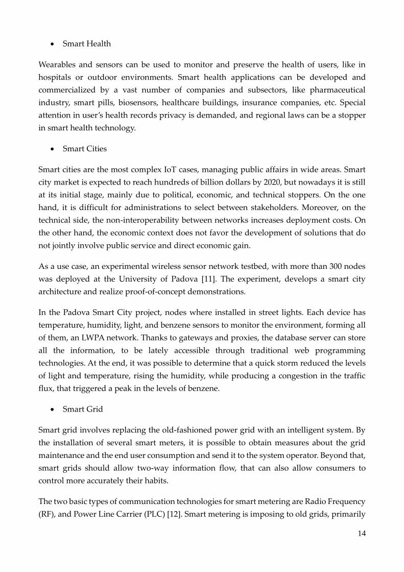
• Smart Health
Wearables and sensors can be used to monitor and preserve the health of users, like in
hospitals or outdoor environments. Smart health applications can be developed and
commercialized by a vast number of companies and subsectors, like pharmaceutical
industry, smart pills, biosensors, healthcare buildings, insurance companies, etc. Special
attention in user’s health records privacy is demanded, and regional laws can be a stopper
in smart health technology.
• Smart Cities
Smart cities are the most complex IoT cases, managing public affairs in wide areas. Smart
city market is expected to reach hundreds of billion dollars by 2020, but nowadays it is still
at its initial stage, mainly due to political, economic, and technical stoppers. On the one
hand, it is difficult for administrations to select between stakeholders. Moreover, on the
technical side, the non-interoperability between networks increases deployment costs. On
the other hand, the economic context does not favor the development of solutions that do
not jointly involve public service and direct economic gain.
As a use case, an experimental wireless sensor network testbed, with more than 300 nodes
was deployed at the University of Padova [11]. The experiment, develops a smart city
architecture and realize proof-of-concept demonstrations.
In the Padova Smart City project, nodes where installed in street lights. Each device has
temperature, humidity, light, and benzene sensors to monitor the environment, forming all
of them, an LWPA network. Thanks to gateways and proxies, the database server can store
all the information, to be lately accessible through traditional web programming
technologies. At the end, it was possible to determine that a quick storm reduced the levels
of light and temperature, rising the humidity, while producing a congestion in the traffic
flux, that triggered a peak in the levels of benzene.
• Smart Grid
Smart grid involves replacing the old-fashioned power grid with an intelligent system. By
the installation of several smart meters, it is possible to obtain measures about the grid
maintenance and the end user consumption and send it to the system operator. Beyond that,
smart grids should allow two-way information flow, that can also allow consumers to
control more accurately their habits.
The two basic types of communication technologies for smart metering are Radio Frequency
(RF), and Power Line Carrier (PLC) [12]. Smart metering is imposing to old grids, primarily

15
in Europe and Asia. Market for smart meters was valued approximately 4$ billion in 2011,
and it is expected to grow to 20$ billion in 2018 [13].
Smart grid is an example of a mMTC system created to support large number of devices,
with low data rates and no mobility, requirements that fit perfectly to the ones for which
NB-IoT (that is technology studied in this thesis) was created to satisfy.

16
2 Enabling technologies for the IoT
This chapter gives an outline of the currently used technologies in LPWA networks and
focuses on the NB-IoT one, that operates in the cellular licensed spectrum.
2.1 Low Power Wide Area Networks
Low Power Wide Area Networks (LPWAN) provide connectivity to low power devices in
wide areas. This type of networks complements the traditional cellular networks and short
range wireless technologies (WLAN, WPAN), when applied to smart environments and
MTC applications. Roughly, LPWA networks try to reach a system range about 20km, where
devices are provided with up to 10 years of battery life, and the cost per device is not
superior than 10$.
The range of this technology is extended using a dense deployment of devices and
gateways, connected using multi-hop mesh networking. There are some standards, design
features, and techniques, that different LPWAN technologies exploit.
As explained before, LPWA networks present a tradeoff between the short-range wireless
networks like ZigBee, Bluetooth, legacy WLANs, Wi-Fi, and the long range cellular
networks, such as GSM or LTE, in terms of connection of low power devices in large areas.
LPWANs are particularly efficient for delay-tolerant mMTC applications.
There are several technologies to enable LPWA networks in both unlicensed (e.g. SIGFOX,
LoRa, Weightless) and licensed spectrum (e.g. LTE-M, NB-IoT), and all them tend to be
narrowband in the spectrum, due to spectral efficiency requirements.
2.1.1 Standardization Efforts on LPWAN
Standardization efforts in LPWA networks are pursued by some Standards Developing
Organizations (SDO) and Special Interest Groups (SIG). In the following, the most
important standardization efforts are briefly reported:
3GPP unites seven telecommunications standard developer organizations and is evolving
their cellular standards to reduce complexity and cost, while improving range and battery
life. Their multiple licensed solutions (LTE, LTE-M, EC-GSM, NB-IoT) offer different
tradeoffs [16]. They try to re-use their cellular infrastructure and spectrum.
ETSI from 3GPP, tries to standardize low data for bidirectional LPWA. They defined use
cases, architectures, protocols, etc., and the interface of the Low Throughput Network (LTN)
[17].

17
IEEE is extending range and reducing power consumption of 802.15.4 and 802.11 standards
with some new specifications at PHY and MAC layers. IEEE have proposed two LPWA
standards as amendments to 802.15.4 low rate WPAN, to enlarge the range of 802.11
standard for WLAN [18].
IETF aims to support LPWA of dominantly proprietary technologies by standardizing end-
to-end IP-based connectivity for low power devices and applications [19].
Some of the most important SIG are LoRa Alliance, Weightless, SIGFOX, and Dash7.
• LoRa is a proprietary physical layer for LPWA connectivity. However, the upper lay-
ers and the system architecture are defined by LoRa Alliance and were released in
July 2015.
• Weightless Special Interest Group proposed three open LPWA standards with dif-
ferent specifications, such as Weightless-W, N, and P.
• DASH7 Alliance is a consortium that defines a full vertical network stack for LPWA
connectivity.
• SIGFOX is a proprietary wireless company, that has developed its own network to
connect multiple devices with low data rates, pretending to extend worldwide in few
years [20].
2.1.2 Main Challenges
As LPWA networks are so complex ecosystems, they should be upgraded and developed in
real time, and present some challenges in the design, that must be faced by the engineering
community. Also, there are several research lines inside the LPWAN topic, some of them in
a state-of-the-art situation. We can summit some of them in the following section.
• Access
Most of the LPWA technologies are based on ALOHA or CSMA MAC access protocols,
which are not good for scale many devices. Research directions to address that topic are
channel diversity, opportunistic spectrum access, or adaptatively transmission strategies
[21].
• Interference Control Mitigation
The interference varies depending on the time, frequency, and space, so devices should
adapt properly to mitigate it, exploiting design diversity in the PHY and MAC layer. Devices
18
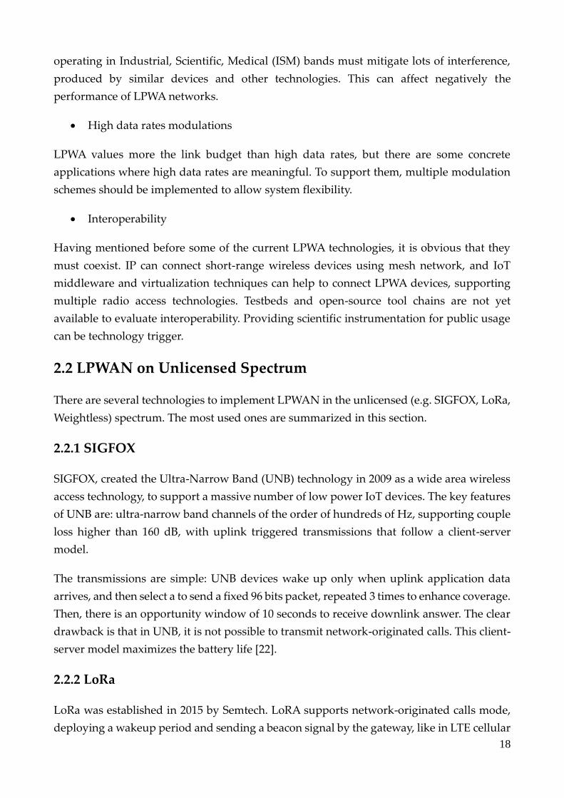
operating in Industrial, Scientific, Medical (ISM) bands must mitigate lots of interference,
produced by similar devices and other technologies. This can affect negatively the
performance of LPWA networks.
• High data rates modulations
LPWA values more the link budget than high data rates, but there are some concrete
applications where high data rates are meaningful. To support them, multiple modulation
schemes should be implemented to allow system flexibility.
• Interoperability
Having mentioned before some of the current LPWA technologies, it is obvious that they
must coexist. IP can connect short-range wireless devices using mesh network, and IoT
middleware and virtualization techniques can help to connect LPWA devices, supporting
multiple radio access technologies. Testbeds and open-source tool chains are not yet
available to evaluate interoperability. Providing scientific instrumentation for public usage
can be technology trigger.
2.2 LPWAN on Unlicensed Spectrum
There are several technologies to implement LPWAN in the unlicensed (e.g. SIGFOX, LoRa,
Weightless) spectrum. The most used ones are summarized in this section.
2.2.1 SIGFOX
SIGFOX, created the Ultra-Narrow Band (UNB) technology in 2009 as a wide area wireless
access technology, to support a massive number of low power IoT devices. The key features
of UNB are: ultra-narrow band channels of the order of hundreds of Hz, supporting couple
loss higher than 160 dB, with uplink triggered transmissions that follow a client-server
model.
The transmissions are simple: UNB devices wake up only when uplink application data
arrives, and then select a to send a fixed 96 bits packet, repeated 3 times to enhance coverage.
Then, there is an opportunity window of 10 seconds to receive downlink answer. The clear
drawback is that in UNB, it is not possible to transmit network-originated calls. This client-
server model maximizes the battery life [22].
2.2.2 LoRa
LoRa was established in 2015 by Semtech. LoRA supports network-originated calls mode,
deploying a wakeup period and sending a beacon signal by the gateway, like in LTE cellular

19
networks. LoRa assigns a variable communication bandwidth for each device to improve
battery life and system capacity. The minimum bandwidth is 125kHz, with coupling loss of
157dB. A LoRa chirp spread spectrum modulation is used to reduce interference effects [23].
2.2.3 Weightless
Weightless-N, by Weightless Special Interest Group (WSIG), supports device-originated
transmission on 200Hz ultra-narrow band channels in the sub-GHz ISM band, like SIGFOX.
Weightless-P, the latest technology by WSIG, supports bi-directional communications, in
12.5kHz narrowband channels, using frequency hopping and spread spectrum as in LoRa.
Weightless-P provides flexible channel assignment and data rates, from 200b/s to 100kb/s
[24].
2.2.4 Unlicensed Spectrum Considerations
Systems in the unlicensed spectrum are operator-less. Unlicensed spectrum presents
interference and non-reliability problems. Moreover, constraints in duty cycle, limits on the
transmitted power, or the need of frequency hopping, can further decrease the system
performance in terms of coverage and capacity.
2.3 LPWAN On Licensed Spectrum
As mentioned before, working in the unlicensed spectrum has the drawback that the service
availability is not guaranteed. Thus, there are some technologies that operate in the licensed
spectrum and can be a real option to develop LPWANs.
Given that the cellular networks are mainly designed for human-type communication, while
LPWAN is mainly for MTC, devices of both technologies are very different. LPWAN
requires low power consumption, small data and infrequent transmissions, less mobility
and cost, while opposite to that, cellular devices, such as an LTE User Equipment (UE), are
complex, with rechargeable batteries and with high performance on data rates and mobility.
To address this difference, LTE-M and NB-IoT were proposed [25]. This section provides a
short review, as later they are compared with the unlicensed spectrum LPWA technologies.
2.3.1 LTE-M
3GPP started studying the supporting of MTC in 2009. In 2016 (Release 13), LTE-M was
introduced to reduce power consumption in low peak rate, simple hardware, and narrow
band operation, in 1.08MHz bandwidth.
The original LTE design is retained, including downlink OFDMA, uplink SC-FDMA,

20
channel codding, etc. The reason to choose 1.08MHz bandwidth, that is six LTE resource
blocks (RBs), is due to the minimum channel requirement of legacy system for channel
acquisition and the random-access [26]. LTE-M provides a coverage extension of 15dB, for
a Maximum Coupling Loss (MCL) of 155dB [27], enabling to reach devices located in areas
with high penetration loss, thanks to temporal repetitions.
2.3.2 Narrowband IoT
3GPP started to standardize NB-IoT air interface in 2015 for LPWAN. NB-IoT operates on a
180kHz bandwidth that can be reduced. Contrary to LTE-M, this bandwidth can be
provided by a 200kHz carrier GSM spectrum.
The MCL is extended 20dB over the 140dB of LTE, achieved through repetitions and BPSK
modulation over a single subcarrier.
NB-IoT retains LTE transmission structure, and as it is the main technology studied in this
thesis, it is deeply explained in section 3.
2.4. Technologies Comparison
As it has stated previously, all the systems being used and developed nowadays for IoT,
tend to present a narrow band (NB) approach. The main reason is that LPWAN objective is
to achieve a high spectral efficiency, to provide enhanced connexion reliability for a massive
number of devices, without providing high data rates.
A fundamental topic in communications is to select the access method and how the capacity
is modified when introducing multiple users. The key resources to transmit information are
power, time, and frequency. Some multiple access methodologies like, TDMA, FDMA,
OFDMA, CDMA, NOMA, and its combinations, are currently used.
• Capacity and coverage extension
The clearest benefit of a reduced transmission bandwidth is that, by considering the same
amount of transmitted power, a higher Signal to Noise Ratio (SNR) can be obtained at the
receiver, because of the reduction of the noise bandwidth, leading to a decreased noise
power. Moreover, reduced bandwidth leads to save more spectrum, with the possibility to
accommodate more devices.
It is possible to convert this gain in spectral efficiency not in data rates, but in a coverage
extension. Doing so, device data rates are lower, but the sensitivity can be improved,
enlarging the link budget.

21
• Power consumption
Battery life is a key factor in low-power massive IoT applications. Typical battery ranges
vary from 300mAh (small devices like wearables) to 5000mAh (e.g. metering devices). The
battery life should vary from days to years, but for low-power applications, up to 10 years
are expected. The current power drawn for a single transmission for IoT devices range
between few milliamps to more than 200mA.
The battery consumption is the product of the current drawn and the operation time.
Consequently, battery life is directly related to the time that the device is not in standby.
• Transmission time
There are two main issues to mention regarding the transmission time in LPWA networks:
1. Because of the delay tolerant nature of many IoT applications, repeating the same
transmit signal to furtherly enhance coverage is a commonly adopted technique.
2. From the Shannon-Hartley theorem, we can conclude that the minimum time to
transmit a message is achieved when the transmission bandwidth is infinite, so there
is a time penalty as the transmission bandwidth is always finite. Then, this
transmission time penalty produces a power consumption penalty, affecting the
battery life.
Although the mentioned time penalty always exists, it can be defined the concept of effective
bandwidth, that provides a threshold. When the effective bandwidth threshold is exceeded,
the effect of increasing the data rates, while spreading the transmission bandwidth, is lower
each time, as it follows a logarithmic growth. If that happens, allocating more bandwidth is
suboptimal for reducing the transmission time (see Figure 2.4-1).
Figure 2.4-1 Bandwidth trade-off
The effective bandwidth provides an optimal balance between transmission time and
spectral efficiency. Then, it is preferable to allocate a bandwidth near to the effective
bandwidth threshold to the device.

22
Technology LTE-M NB-IoT LoRa SIGFOX UNB
Sensitivity -132dBm -137dBm -137dBm -147dBm
Minimum
bandwidth
180 kHz 3.75 kHz 125 kHz 100Hz or
600Hz
Effective
bandwidth
10kHz 3 kHz 3 kHz 300Hz
Table 2.4-1 LPWAN technologies comparison
Table 2.4-1 compares the LPWA technologies in terms of minimum transmission and
effective bandwidth [28].
As LTE-M is constrained to the resource block of 180kHz, NB-IoT offers a better
performance in terms of effective bandwidth.
SIGFOX UNB has a much smaller bandwidth to match the enhanced coverage and stays
close to the effective bandwidth. LoRa, has the same coverage than NB-IoT, but with greater
bandwidth due to spread spectrum to deal with interference. Even though, NB-IoT is
deployed in the licensed spectrum.
This thesis does not pretend to prove better any technology, as they may be useful in
different applications and customers considerations, but to provide a technical comparison
between the different LPWAN commonly used technologies. In the next section, NB-IoT
legacy technology LTE is explained, as it is the precursor of NB-IoT.
23
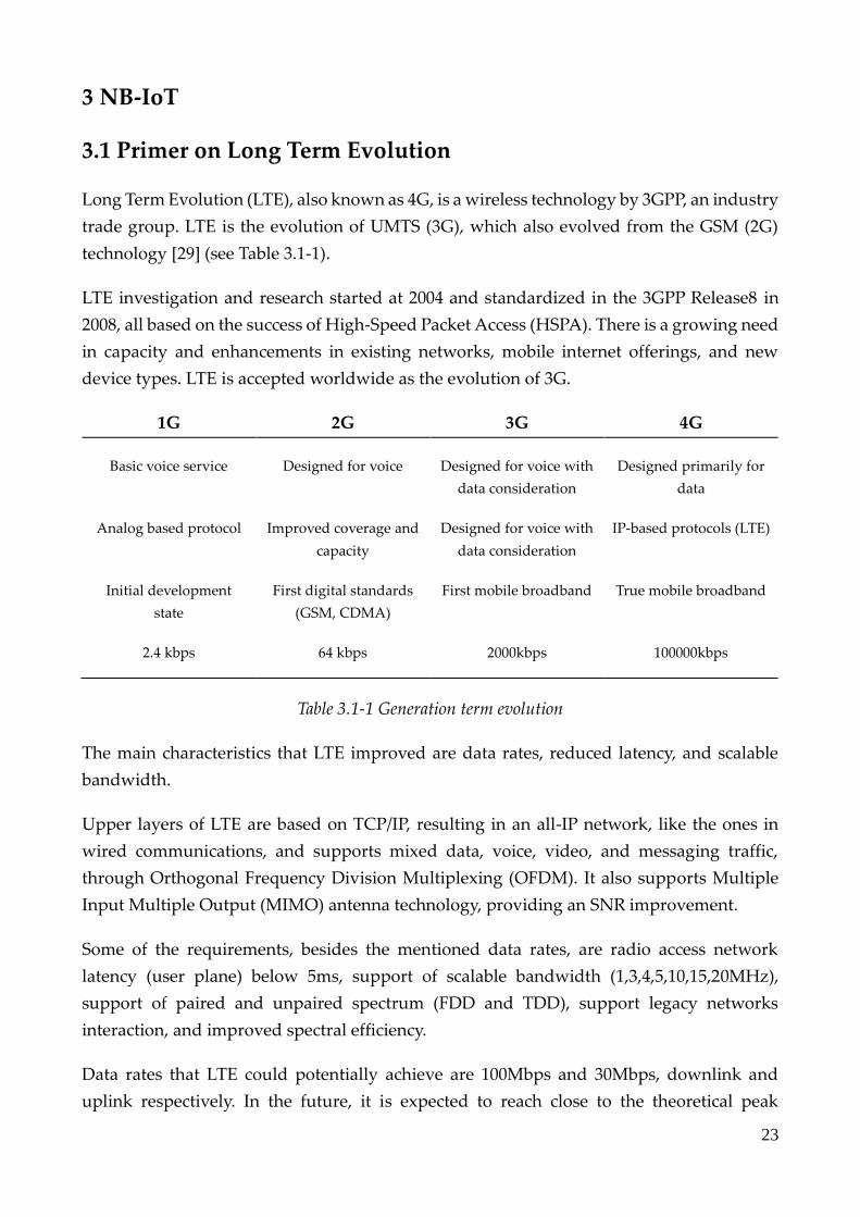
3 NB-IoT
3.1 Primer on Long Term Evolution
Long Term Evolution (LTE), also known as 4G, is a wireless technology by 3GPP, an industry
trade group. LTE is the evolution of UMTS (3G), which also evolved from the GSM (2G)
technology [29] (see Table 3.1-1).
LTE investigation and research started at 2004 and standardized in the 3GPP Release8 in
2008, all based on the success of High-Speed Packet Access (HSPA). There is a growing need
in capacity and enhancements in existing networks, mobile internet offerings, and new
device types. LTE is accepted worldwide as the evolution of 3G.
1G 2G 3G 4G
Basic voice service Designed for voice Designed for voice with
data consideration
Designed primarily for
data
Analog based protocol Improved coverage and
capacity
Designed for voice with
data consideration
IP-based protocols (LTE)
Initial development
state
First digital standards
(GSM, CDMA)
First mobile broadband True mobile broadband
2.4 kbps 64 kbps 2000kbps 100000kbps
Table 3.1-1 Generation term evolution
The main characteristics that LTE improved are data rates, reduced latency, and scalable
bandwidth.
Upper layers of LTE are based on TCP/IP, resulting in an all-IP network, like the ones in
wired communications, and supports mixed data, voice, video, and messaging traffic,
through Orthogonal Frequency Division Multiplexing (OFDM). It also supports Multiple
Input Multiple Output (MIMO) antenna technology, providing an SNR improvement.
Some of the requirements, besides the mentioned data rates, are radio access network
latency (user plane) below 5ms, support of scalable bandwidth (1,3,4,5,10,15,20MHz),
support of paired and unpaired spectrum (FDD and TDD), support legacy networks
interaction, and improved spectral efficiency.
Data rates that LTE could potentially achieve are 100Mbps and 30Mbps, downlink and
uplink respectively. In the future, it is expected to reach close to the theoretical peak

24
throughput of 300Mbps, using the 4x4 MIMO 20MHz bandwidth setup.
3.1.1 Frequency and Modulations
LTE allows flexibility in the channel bandwidth, with values of 1.4, 3,5, 10, 20MHz, where
the smallest entity for resource assignment is the Resource Block (RB) of 180kHz, for both
Uplink (UL) and Downlink (DL). Some modulation schemes available are QPSK, 16QAM,
64QAM. The multiple access is performed OFDMA in DL and SC-FDMA in UL.
LTE frequency bands are specified in 3GPP specifications.
3.1.2 Network Architecture
LTE network architecture is divided in 3 sections, the User Equipment (UE), the Evolved
UMTS Terrestrial Radio Access Network (E-UTRAN), and the Evolved Packet Core (EPC)
(see Figure 3.1.2-1).
Figure 3.1.2-1 LTE network architecture
1) User Equipment:
The UE architecture in LTE is equivalent to the one used in UMTS and GSM, previously
known as Mobile Equipment (ME), where each ME is comprised by the modules of:
Mobile Termination (MT), that handles communication functions, the Terminal Equipment
(TE), that terminates data streams, and the Universal Integrated Circuit Card (UICC),
known as the SIM card for LTE equipment. The Universal Subscriber Identity Module
(USIM), stores user specific data like 3G SIM card, and keeps the information about security
keys, home network identity and phone number.
2) E-UTRAN:

25
The E-UTRAN is the access network that handles the radio communications between the
UE and the core and counts with several base stations known as eNodeB (eNB).
Figure 3.1.2-2 shows a common LTE eNodeB.
The function of the eNB, is to send and receive radio transmissions using the digital and
analogue functions of the LTE air interface, controlling the power of the communication
links sending signaling and handover messages.
Figure 3.1.2-2 LTE base station
Each eNB connects with the EPC by the S1 interface and with other base stations with the
X2 interface.
3) Evolved Packet Core:
The EPC communicates with packet data networks in the outside world, like Internet,
private corporate networks, IP multimedia subsystem, etc. There are lots of complex
modules inside the EPC core network, that can be seen in [30].
• The Home Subscriber Server (HSS), that is a central database with information
about all the network operator’s subscribers.
• The Serving Gateway (SGW) acts like a router, enabling communication between
base station and PGW.
• The Packet Data Network Gateway (PGW), communicates with the outside servers.
• The Mobility Management Entity (MME) controls high-level operation of the mo-
bile with signaling messages and the HSS.

26
3.1.3 Protocol Stack
The LTE protocol stack is explained in this sub-section and can be observed in Figure 3.1.3-
1. A IP packet encapsulation can be observed in Figure 3.1.3-2.
Figure 3.1.3-1 LTE Protocol Stack scheme
In LTE, packets received from a layer are called Service Data Unit (SDU), and the output of
a layer packet is called Protocol Data Unit (PDU). The layers that conform the protocol stack
are the following ones (see Figure 3.1.3-1):
• The Physical Layer (PHY), is the first one and the one that carries all the information
from the MAC transport channels over the air interface. That layer oversees the link
adaptation, the cell search, power control, and other measurements for the Radio Re-
source Control (RRC) layer.
• The Medium Access Layer (MAC), is the one that performs the mapping between the
logical and transport channels. Main functions are multiplexing of MAC PDUs from
one logical channel to Transport Blocks (TB), delivered from the PHY layer on
transport channels, scheduling information reporting, error correction (HARQ), pri-
ority handling between UEs and logical channels, etc.
• The Radio Link Control (RLC), has three modes of operation (Transparent,
Unacknowledged, and Acknowledged), and is responsible to transfer of upper layer

27
PDUs, error correcting (ARQ), and the segmentation and reassembly of RLC PDUs,
among others.
• The Packet Data Convergence Control (PDCP), oversees header compression of IP
data, transfer of data, maintenance of PDCP sequence numbers, delivery between
layers, duplicate elimination, ciphering of user plane and control plane data, integrity
protection and verification, etc.
• Radio Resource Control (RRC) protocol is used in UMTS and LTE on the air interface.
It is a layer that exists between UE and eNB and exists at the IP level. This protocol
is specified by 3GPP in TS 25.331 for UMTS and in TS 36.331 [31] for LTE. RRC mes-
sages are transported via the PDCP-Protocol. The Radio Resource Control (RRC) pro-
tocol, performs connection establishment and release functions, broadcast of system
information, radio bearer setup and release, mobility procedures, paging notification,
etc.
• The Non-Access Stratum (NAS) protocols form the highest layer of the control plane
between the UE and the MME. They support the mobility of the UE and the session
management procedures, to maintain IP connectivity between UE and PGW.
3.1.4 Channels Overview
The information flows between protocols using different types of logical, transport, and
physical channels (see Figure 3.1.4-1), that are distinguished by the type of information.
• Logical channels, that define what type of information is transmitted over the air.
Data and signaling messages are transmitted on logical channels between RLC and
MAC.
• Transport channels, that define how and with what type of characteristics the data is
transferred by the PHY layer. Data and signaling messages are carried between the
MAC and the PHY layer.
• Physical channels, where data and signaling messages are exchanged in UL and DL.
There are two types of physical channels, the data channels and the control channels,
that are explained in their own section.
In thesis, we focus in the uplink physical transport channels, as are the ones that are going
to be studied in the ns-3 simulations. More information about the different data and control
channels in LTE can be found in [32].

28
3.1.5 Physical Layer
3.1.5.1 Downlink: OFDMA Modulation and Frame Structure
In OFDM, each available bandwidth is divided in multiple subcarriers, that can be
independently modulated. Compared with the single carrier transmission (SC TX), since the
multiple subcarriers transmit in parallel, the bandwidth is divided into narrower flat fading
subchannels, improving the system robustness.
The signal generation chain flows in the subsequent manner (see Figure 3.1.5.1-1): operation
produces an OFDM symbol through an Inverse Fast Fourier Transform (IFFT), and a Cyclic
Prefix (CP), that protects from Inter Symbol Interference (ISI) is added finally. On the
receiver part, there is an Fast Fourier Transform (FFT) to reverse the process. There is a lot
of available literature regarding OFDM technique [33] (see Figure 3.1.5.1-1).
Figure 3.1.5.1-1 OFDM symbol generation
Normal CP with 5.2us for the first symbol and 4.7us for the others is used. The subcarriers
have a typical spacing of 15kHz, and the bandwidth is scalable. To support transmission in
paired and unpaired spectrum, two duplex modes are supported, Frequency Division
Duplexing (FDD) and Time Division Duplexing (TDD).
Radio frame structure type 1 is allocated in FDD, used in DL. It has duration of 10ms with
20 slots of 0.5 ms each (1 small slot of 0.5ms is considered a Resource Block (RB)) (see Figure
3.1.5.1-2). There are 6 or 7 OFDM symbols on each slot, depending if the CP is extended or
normal (see Figure 3.1.5.1-2).

29
Figure 3.1.5.1-2 LTE FDD frame structure
Radio frame structure type 2 is transmitted in TDD, used in UL, and consists of two half
frames of 5ms, that count each one with 5 subframes of 1ms. There are 7 uplink-downlink
configurations for TDD (see Figure 3.1.5.1-3).
Figure 3.1.5.1-3 LTE TDD frame structure
1 subframe is of 1ms and represents 2 RBs. A PRB is defined as a pair of 12 consecutive
subcarriers with one slot duration of 0.5ms. 12*6=72, are the OFDM symbols per time slot.
LTE physical layer supports any bandwidth from 1,4 to 20MHz in steps of 180kHz (RB). LTE
supports a subset of 6 different system bandwidth. All UEs must support the maximum
bandwidth of 20MHz.
3.1.5.2 Uplink: SC-FDMA Modulation
OFDMA has some disadvantages, the major one is the high Peak to Average Power Ratio
(PAPR). As the transmitted signal is the sum of all modulated subcarriers, some of them are
in phase. Then, high amplitudes are not avoidable. The high PAPR requires high AC/DC
converter resolution and causes out of band spurious radiation. In DL it is not a problem,
but it is impossible to manage in the UL (see Figure 3.1.5.2-1).
Discrete Fourier Transform (DFT) pre-coding is performed on modulated data symbols to
transform them into frequency domain, then, a subcarrier mapping allows flexible
allocation. Finally, the CP is inserted. This DFT pre-coding is the main difference between
UL and DL modulations. In this UL method, each subcarrier has a portion of superposed
symbols [34].

30
Figure 3.1.5.2-1 OFDMA and SC-FDMA pre-coding scheme comparison
So, each sub-carrier contains information of all transmitted symbols. The SC-FDMA mode
fits better to the overall system requirements of LTE, as the goal is to lower the PAPR (see
Figure 3.1.5.2-2).
Figure 3.1.5.2-2 OFDMA and SC-FDMA carrier comparison with QPSK modulation
3.1.5.3 Uplink Physical Channels and Signals
There are some LTE Uplink Physical Channels:
• Physical Uplink Shared Channel (PUSCH) that carries user data.
• Physical Uplink Control Channel (PUCCH) that carries control information.

31
• Physical Random-Access Channel (PRACH), for preamble transmission for initial ac-
cess.
Also, the LTE Uplink physical signals are two, the Demodulation Reference Signals (DRS),
that enables channel estimation and data demodulation, and the Sounding Reference
Signals (SRS) that enables uplink channel quality evaluation.
Demodulation Reference Signals (DRS) are transmitted in the UL, over the entire allocated
bandwidth, and occupies a specific single carrier FDMA symbol. Sounding Reference
Signals (SRS) are used to estimate uplink channel quality on other frequency areas.
Physical Uplink Control Channel (PUCCH) carries Uplink Control Information (UCI) when
PUSCH is unavailable. If PUSCH is available, means that resources have been allocated to
the UE for data transmission, UCI are multiplexed with user data.
Uplink Control Information (UCI) are Scheduling Requests (SR), ACK/NACK of DL data
packets, CQI, Precoding Matrix Information (PMI) and Rank Indicator (RI) for MIMO.
PUCCH is transmitted on reserved frequency regions configured by higher layers.
3.1.6 Attachment and Random-Access Procedures
Each UE must compile some cell information to complete a successful attachment:
• Cell ID (0 to 503)
• Cyclic Prefix (Normal or Extended)
• Multiplexing technique (FDD or TDD)
• Cell Bandwidth
In DL, LTE uses 2 types of signals, known as Primary and Secondary Synchronization
Signals (PSS and SSS), that provide acquisition of cell timing and identity, and Downlink
Reference Signal (DRS), for cell search, acquisition, demodulation and channel estimation.
LTE information transport is carried in Downlink Physical Channels (DPC). LTE radio cell
is identified by the physical layer cell identity group. This information is transmitted by the
PSS and SSS. SSS are transmitted in first and sixth subframe, so the repetition time between
synchronization signals is 5ms.
Also, each UE must follow some further steps before transmitting data:
• Cell Search and Selection Procedure
32
• Random Access Procedure
• Derive System Information
Random Access Procedure consists in a Random-Access Preamble, Random Access
Response, Scheduled Transmission, and Contention Resolution. After the procedure, UE
can receive data, transmitted in the PDSCH. The device must know scheduling information,
transmitted in PDCCH.
There is Hybrid Automatic Repeat Re-Quest (HARQ) in the LTE downlink. It is transmitted
in the PUCCH or in PUSCH, depending if there is data transmission in parallel.
EPS Bearer Setup is a connection-oriented transmission network, that requires a virtual
connection between UE and core network (EUTRAN) before any traffic can be sent. This
virtual connection provides a transport service with a specific Quality of Service (QoS). It
must cross multiple interfaces to achieve this connection, and a lot of produces and
information are stablished.
3.1.7 Additional features
• Mobility
The way an UE changes the attached eNB is known as handover. This procedure proceeds
as:
1. UE makes measurement reports, and source eNB takes a handover decision and com-
municates to another eNB (target eNB). Second eNB decides and sends ACK if hand-
over is feasible.
2. First eNB sends to UE an RRC connection reconfiguration, to able UE access the tar-
get cell. The UE realizes the change, detaching from old, and delivering packets to
the new eNB, using buffers.
In LTE there are only 2 protocol states defined in the Radio Resource Control (RRC),
connected or idle. LTE can interwork with 2G and 3G. Mobility is not considered in NB-IoT.
• MIMO
Multiple Input Multiple Output (MIMO) is one important characteristic of LTE as it enables
to reach the desired throughput and communication requirements. Multiple antennas are
used in the radio channels to transmit and receive. As MIMO is not used in NB-IoT, there is
a reference for the interested reader [35].

33
3.2 From LTE to LTE-Advanced
LTE Advanced (LTE-A) is an enhancement of the LTE standard. 3GPP, in late 2009,
presented Release 10, this communication system to meet the requirements of the IMT-
Advanced, also known as 4G. LTE-A is focused on achieve higher capacity, providing higher
bit rates in a more efficient manner, and at the same time, fulfil the mentioned requirements
set by ITU. The above-mentioned objectives differ from the ones in the LPWA network with
low data rates that this thesis studies, so only the most important concepts introduced in
LTE-A are mentioned. The interested reader can refer to [36] for a detailed overview.
The main new functionalities introduced by LTE-A are Carrier Aggregation (CA), the
introduction of Relay Nodes (RN) to achieve more efficient heterogeneous network
planning, Coordinated MultiPoint’s (CoMP) to improve performance in cell edges,
enhancements in MIMO and Inter-Cell Interference Coordination (eMIMO and eICIC), plus
the evolution towards Self Organizing Networks or 256QAM.
3.3 NB-IoT Technology
NB-IoT is a narrowband radio technology introduced by 3GPP in Release 13, specifically
tailored for providing wide-area coverage for ultra-low-end IoT and MTC applications. NB-
IoT enables cost-efficient and flexible massive MTC deployments with LTE cellular system
functionalities, achieving improved coverage to many low power devices, with low peak-
data rates each one. The minimum system bandwidth required to operate is 180kHz, equal
of the smallest LTE Physical Resource Block (PRB), that can be reduced in a so-called multi-
tone configuration.
NB-IoT can enhance coverage up to 20 dB thanks to signal repetitions, compared to legacy
LTE technology, allowing up to 52000 devices per channel per cell, each of those with up to
10 years of battery life. Moving apart from the reliability limitations and interferences in the
unlicensed spectrum, NB-IoT offers a suitable solution in the licensed spectrum.
NB-IoT acquires almost all features of legacy LTE, including numerologies, downlink
OFDMA and uplink SC-FDMA, channel coding, interleaving, etc. So on, the same
infrastructure can usually be used, reducing significantly the time required to develop full
specifications. If hardware recycling is not an option, NB-IoT can be supported with a
software upgrade. Because of that, NB-IoT can be deployed partially with the pre-existing
infrastructure and then be gradually implemented. Such facilitates in the deployment of the
technology also reduce the costs severely.
Inside Release 13, the designers detailed targets for all deployment operations, including

34
[37]:
• Improved indoor coverage of 20dB compared to GPRS devices, that correspond to a
maximum coupling loss (MCL) of 164dB. At application layer, with this MCL, data
rates around 160bps should be achieved in both uplink and downlink. From those
20dB, 6dB are because the reduced bandwidth, and the other due to multiple repeti-
tions. Discontinuous reception (DRX), enables battery saving allowing devices to
sleep mode. NB-IoT new feature of extended DRX cycles reach up to 10s for UEs in
connected state and about 3 hours for UEs in idle state.
• Up to 50000 devices that rarely send message to the network within a cell-site sector
should be supported. The whole system should offer coverage to millions of devices.
• Reduced complexity devices with a battery of 10 years with a typical battery capacity
of 5Wh at 164dB MCL.
• The latency requirements are very flexible as it is not usually a requirement for
MMTC, but there is a fixed upper bound of 10 seconds for 99% of the devices.
All in all, main NB-IoT advantages are low power and consumption, low complexity in the
UEs and low cost for the radio chip, plus a significant coverage enhancement.
3.3.1 Operation Modes
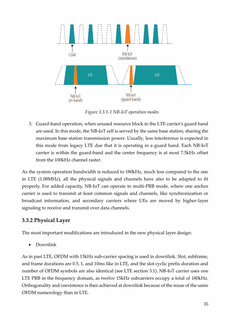
As stated before, NB-IoT can operate in three differentiated modes [38] (see Figure 3.3.1-1):
1. Standalone operation, when the carrier occupies one GSM carrier. This is an option
when LTE is deployed in a higher band and GSM is still in use, providing coverage
for basic services.
2. In-band operation, when one or more LTE PRBs are reserved for NB-IoT. In this
mode, there are some scheduling restrictions, as some resources are restricted to LTE
usage. Even though being different technologies, the same the eNBs power can be
shared between LTE and NB-IoT efficiently.
35
Figure 3.3.1-1 NB-IoT operation modes
3. Guard-band operation, when unused resource block in the LTE carrier's guard band
are used. In this mode, the NB-IoT cell is served by the same base station, sharing the
maximum base station transmission power. Usually, less interference is expected in
this mode from legacy LTE due that it is operating in a guard band. Each NB-IoT
carrier is within the guard-band and the center frequency is at most 7.5kHz offset
from the 100kHz channel raster.
As the system operation bandwidth is reduced to 180kHz, much less compared to the one
in LTE (1.08MHz), all the physical signals and channels have also to be adapted to fit
properly. For added capacity, NB-IoT can operate in multi-PRB mode, where one anchor
carrier is used to transmit at least common signals and channels, like synchronization or
broadcast information, and secondary carriers where UEs are moved by higher-layer
signaling to receive and transmit over data channels.
3.3.2 Physical Layer
The most important modifications are introduced in the new physical layer design:
• Downlink
As in past LTE, OFDM with 15kHz sub-carrier spacing is used in downlink. Slot, subframe,
and frame durations are 0.5, 1, and 10ms like in LTE, and the slot cyclic prefix duration and
number of OFDM symbols are also identical (see LTE section 3.1). NB-IoT carrier uses one
LTE PRB in the frequency domain, as twelve 15kHz subcarriers occupy a total of 180kHz.
Orthogonality and coexistence is then achieved at downlink because of the reuse of the same
OFDM numerology than in LTE.

36
• Uplink
On the uplink, NB-IoT allows single and multi-tone operations. Single-tone operation mode
can vary in bandwidth from 3.75kHz to 15kHz. Multi-tone transmission is according to SC-
FDMA, with 15kHz of spacing, with 0.5ms slot and 1ms subframe like in LTE. In downlink
and 15kHz version of uplink transmissions, one NB-IoT carrier has 12 sub-carriers. [39].
Operation Modes In-band and Guard band in LTE, Standalone
MCL (Coverage) 164 dB
Downlink OFDMA (15kHz subcarrier spacing), 1Rx, 2Txantenna
Uplink SC-FDMA (15kHz subcarrier spacing), Turbo Code or Single
Tone (15kHz and 3.5kHz spacing)
Bandwidth 180kHz (1 PRB), inside eNB assigned BW
Peak data rate 250kbps (20kbps UL single tone)
Duplex FDD, TDD
Power class 23dBm
Power saving PSM, ext. I-DRX, C-DRX
Table 3.3.2-1 NB-IoT main features
The subframe duration is of 1ms like in LTE. Hence, there is not enough frequency-domain
space for the multiplexing of physical channel. All downlink channels are multiplexed in
time, some of them spanning multiple subframes. Half-duplex operation is adopted to save
battery and complexity, so an UE cannot transmit and monitor simultaneously.
3.3.3 Physical Channels and Signals
Less channels and signals are supported in NB-IoT than in LTE. It must be noticed that there
is no uplink control channel in NB-IoT, so uplink acknowledgement must be transmitted in
the NB-PUSCH later explained, while scheduling request must be indicated using random
access procedure.
There are four physical layer downlink channels in line with LTE design, that are the
Physical Broadcast Channel (NB-PBCH), the Physical Downlink Control Channel (NB-

37
PDCCH), the Physical Downlink Shared Channel (NB-PDSCH), and the Physical downlink
synchronization channel for PSS and SSS signals (see Table 3.3.3-1) [40].
• NB-PBCH is the broadcast channel that carries the Master Information Block (MIB)
of 34 bits, transmitted in the first subframe of each radio frame, with a periodicity of
10ms. MIB includes System Information Block (SIB) for scheduling, number of an-
tenna ports and use mode.
• NB-PDCCH utility is to transmit Downlink Control Information (DCI) with schedul-
ing information for both uplink and downlink data transmissions. Resources are
grouped into control channel elements (CCE), that occupy six sub-carriers of a sub-
frame, so there are 2 CCEs per subframe. This means that the control information,
fixed at 23 bits, is encoded over 1 subframe. Coverage extension is achieved using
repetition coding, with up to 2048 repetitions.
• NB-PDSCH allows downlink payload Transport Blocks (TB) transmission. Schedul-
ing information about NB-PDSCH is sent over NB-PDCCH. The smallest Resource
Unit (RU), is one carrier that occupies one subframe. The minimum size of each in-
formation block is 256 bits, and the maximum size of a TB is limited to 680 bits. It is
important to notice that only QPSK is supported. The TB bits are encoded through
Tail-Biting Convolutional Coding (TBCC).
Link Physical Channels and Signals
Downlink Narrowband Physical Downlink Control Channel (NB_PDCCH)
Narrowband Physical Downlink Shared Channel (NB-PDSCH)
Narrowband Physical Broadcast Channel (NB-PBCH)
Narrowband Synchronization Signal (NB-PSS/NB-SSS)
Uplink Narrowband Physical Uplink Shared Channel (NB-PUSCH)
Narrowband Physical Random-Access Channel (NB-PRACH)
Table 3.3.3-1 NB-IoT physical channels
For the synchronization and Reference Signal (NB-RS), downlink is also used. In uplink,
there are two channels, the physical uplink shared channel (NB-PUSCH), and the physical
random-access channel (NB-PRACH).

38
• NB-PUSCH is the channel that carrier the UE TBs (NB-PUSCH Format 1) and uplink
control information (UCI or NB_PUSCH Format 2). It involves that contrary to LTE,
both data and control information are carried over the uplink shared channel, be-
cause that two different formats. The RU varies between 2 to 16 slots depending of
the tones, that can be 1, 3, 6, or 12. The slot length is 0.5ms and 2ms for subcarrier
spacing of 15kHz and 3,75kHz respectively. Then, and contrary to the LTE uplink,
the 1ms time is not fixed at RU.
• NB-PRACH provides connexon between the user and the base station. The base uses
the random-access preamble sent by a user terminal to estimate the uplink timing, to
maintain uplink orthogonality between many users. NB-PRACH uses single-tone
transmission and 3.75kHz sub-carrier spacing. The preamble transmission can be re-
peated to 128 times in contiguous subframes. The base station can configure to three
NB-PRACH, each one with its coverage level. Each NB-PRACH is defined by perio-
dicity, number of repetitions, and a set of sub-carriers.
Legacy LTE synchronization sequences occupy 6 PRBS, so new Synchronization Signals
(SS), that are the primary (NB-PSS) and secondary (NB-SSS) synchronization signals have
been introduced to handle the signaling. NB-PSS is transmitted in the fifth every 10ms, using
the last 11 OFDM symbols in the subframe. The NB-PSS detection is one of the most
demanding processes for the UE in terms of computation.
3.3.4 Signal Repetitions
Signal repetition technique is used in NB-IoT to enhance coverage, depending on the
condition of the channel between the UE and the eNB. For transmissions on NB-PDCCH
and NB-PDSCH, up to 2048 possible repetitions are allowed, and 128 in the NB-PUSCH.
Repetitions can improve SNR up to 33dB and 20dB in both downlink and uplink. The
channel estimation error is a factor to improve when working in bad SNR conditions [41].
3.3.5 Deployment Considerations
3.3.5.1 LTE Coexistence
Operators face the problem to integrate NB-IoT technology in fractions of their existent
networks. A partial network deployment presents some deployment problems. One PRB
used for NB-IoT in a cell, could be used for LTE in other close cells, compromising the
system availability. Sparse deployment of NB-IoT results in a wider area to be covered by
NB-IoT cells, so remote NB-IoT devices from the serving cell could be close to another LTE
cell, causing destructive co-channel interference. To manage this coexistence problem,
power boosting of the PRB can be used, stealing power from other PRBs, with limit 6 dB.

39
Resource mapping is also designed to ensure an efficient performance when NB-IoT is
deployed inside LTE carrier, avoiding mapping NB-IoT signals to the resource elements
used in LTE, ensuring orthogonality (see Figure 3.3.5.1-1).
Figure 3.3.5.1-1 LTE and NB-IoT interference scheme
For the stand-alone and guard-band operation modes, no LTE resource must be protected,
but for in-band operation, interference can occur. To mitigate that, NB-IoT UEs can learn the
deployment mode and the cell identity through initial acquisition and notice which resource
elements are used by LTE. Finally, the UE can map symbols to available resource elements.
NB-PSS and NB-SSS need to be detected without knowing the deployment mode, but there
are some common strategies to avoid this concrete problem, like avoiding the usage of the
first three OFDM symbols in every subframe, that may be used by LTE PDCCH [42].
Nevertheless, de-synchronization can lead to interference.
3.3.5.2 Synchronization
When an UE is firstly attached to an eNB, the synchronization must be precise enough to
distinguish the cell via NB-PCID, and to obtain the first subframe and frame reference
number. NB-IoT UEs are designed with crystal oscillators that may introduce Carrier
Frequency Offset (CFO), and some modes of operation (in-band and guard-band) can even
introduce higher CFO. NB-IoT synchronization is designed very similarly to LTE
synchronization, but with some variations to ensure that UEs in high pathloss and low SNR
condition (e.g. UEs placed on basements) can correctly communicate.
As explained previously, synchronization is carried out by the usage of NPSS and NSSS
signals. NPSS obtains the symbol timing and CFO, and NSSS obtains the NB-PCID.
3.3.5.3 Device Complexity

40
NB-IoT UEs are designed to be simple. With respect to LTE UEs, they only require a single
antenna (no MIMO), single HARQ process, no need of complex coding, only mobility
measurements in Idle mode, low sampling rate due to lower bandwidth, and only half-
duplex frequency-division duplexing (FDD) operation. The coverage objective is achieved
with a transmission power of 20 or 23 dBm [43].
3.3.6 Main Differences between NB-IoT and LTE
This section summarizes the main differences between both technologies, as NB-IoT will be
performed in the network simulator, and some modifications in the LTE module will have
to be applied, given the fact that NB-IoT module does not already exists.
3.3.6.1 Physical Layer
NB-IoT is a technology created for MTC with no need of mobility. There is no interaction
with other radio technologies and most of the LTE-A features are not implemented: there is
not interference avoidance for in-device coexistence, no Carrier Aggregation, no device-to-
device services, the concept of QoS is missing, etc.
In the in-band operation mode, NB-IoT has available only some RBs. There are two coverage
enhancement areas in NB-IoT, CE1 and CE2 to reach higher MCL of 154 and 163 dB.
Then, a UE that in LTE should be considered out of range, may transmit and receive in NB-
IoT thanks to the signal repetitions in CE1 and CE2.
3.3.6.2 Full Duplex (Uplink vs. Downlink)
• Downlink
There are less channels in the DL, as there is not Multicast, Broadcast, Paging, or Shared
Downlink Channels. In DL, only QPSK modulation is applied. Note that a detailed analysis
is out of the scope of that thesis, that focuses on uplink performance.
• Uplink
In NB-IoT uplink, all signals are transmitted over the NB-Physical Uplink Shared Channel
(NB-PUSCH), so there is no channel equivalent to the Control channel in LTE.
While in LTE the UL subframe structure is quite like the DL one, in NB-IoT they can be
different. The subcarrier spacing may be 3.75kHz, instead of the 15kHz in DL. Then, this
leads to a fourfold transmission time, from 0.5 to 2ms for each slot. The uplink maintains
the SC-FDMA scheme as explained in LTE, with BPSK or QPSK modulations.

41
4 Network Simulator 3
NS-3 is a free software discrete-event network simulator, created primarily for research and
development use. NS-3 have a simulation core, documented in its own website, and can
provide flexibility in the design and configuration of the network. The simulator does not
provide an IDE, so the simulation compiling, and execution are done by command line. The
network simulator can collect traces and analyze them, and the principal technologies that
are tested in ns-3 are Wi-Fi, WiMAX, and LTE, running wireless/IP simulation in layers PHY
and MAC.
4.1 Simulation modules
Technically, ns-3 is a C++ library that provides network simulation models implemented as
C++ objects. NS-3 provides a public API that includes a tutorial, a manual, and a model
library with source code. Inside the model library, we can find some of the models that are
going to be used, the most important ones in this work are:
• Antenna Module
• Buildings Module
• Flow monitor
• LTE Module
• Internet Models (IP, TCP, Routing, Applications)
• Mobility
• Network Module
• Propagation Module
• Antenna Module
The antenna module provides an interface to model the radiation of the antenna, and a set
of classes with different radiation patterns that define each type of antenna. The antenna
model, is defined in spherical coordinates and returns a value of the gain (in dB), only
considering the angular direction. Inside the antenna module, we can find three antenna
models, that are the isotropic antenna model (used in our indoor base station), the cosine
antenna model (used in our outdoor base stations), and the parabolic antenna model.
• Buildings Module
The buildings module provides the building class that reproduces the presence of buildings
in the simulation scenario, the mobility building info, that allows to specify the location,
size, and characteristics of the buildings, plus some useful channel models like the hybrid
buildings model bye ns-3, the ITUR1238, or the Okumura-Hata model.

42
If class, the building floors, area, separation, walls, and other parameters, are modified to fit
with the desired scenario.
• Flow Monitor Module
The flow monitor provided by ns-3 provides a flexible system to make measurements of the
network’s performance. If the module is installed in the network nodes, it can track packet
exchanges at IP level, dividing all the communications in work flows, that are organized in
the tuple {protocol, source (IP, port), destination (IP, port)}. Statistics can be exported in XML
format and analyzed in NetAnim.
The flow monitor has some limitations, and since the packets are tracked at IP level, any
retransmission will be a new packet.
Important data provided by the flow monitor is the delay, transmitted and received bytes
and packets, and the time of first and last reception or transmission. With that information,
we can compute the bytes lost ratio and the throughput of each individual node.
• LTE Module
Inside the LTE module, ns-3 provides an LTE model that includes radio protocol stack (RRC,
PDCP, RLC, MAC, and PHY), that reside entirely inside the UE and eNB nodes. Also, there
is an EPC model, that includes core network interfaces, protocols and entities, including
SGW, PGW, and MME nodes. The model has been designed for testing radio resource
management, QoS, dynamic spectrum access and ICI, among others. The granularity is at
least of one RB, and the module is designed to run for tens of eNBs and hundreds of UEs
because of computational requirements. It is possible to manage different eNBs that work
in different frequency bands.
The LTE model is used to simulate transmission of IP packets by upper layer, and it should
be considered that in LTE the scheduling and radio resource management do not work in
IP packets directly, but in RLC PDUs, which are obtained by segmentation and
concatenation of IP packets by RLC entities.
The EPC model provides end-to-end IP connectivity over LTE model, and only supports
IPv4 so far.
• Mobility Module
The mobility module allows the user to track the cartesian position and speed of each UE,
with high level of flexibility as the mobility can course changes inside the simulation. Also,
it provides some helpers used to place nodes and setup the mobility models. Inside mobility,

43
we can find useful classes as rectangle, box, and functions as GetPosition () or
GetDistanceFrom (). There are also position allocators used to set initial positions, but in our
non-mobility case studio will suppose the final and static placement of the UEs.
• Propagation Module
The propagation module defines the interfaces of the propagation loss and delay. The most
important is the propagation loss model, because thanks to it we can model the channel.
There are some channels included in ns-3, like Cost231, Friis, OkumuraHata,
ThreeLogDistance, etc.
The ones that we are going to use are the ItuR1411NlosOverRooftop and the ItuInh
propagation models. They are deeply explained in the next channel model section.
4.2 Propagation Channel Models
The channel models used in the work are the ITU R1411 NLOS Over Rooftop, for the
outdoor base stations, and the ITU Indoor Hotspot (ITU InH), for the indoor base stations.
4.2.1 Outdoor: ITUR1411NLOS Over Rooftop
This model is designed for Non-Line-of-Sight (NLOS) short range outdoor communication,
and adequate for the frequency range between 300MHz and 100GHz. It includes some
buildings parameters that can be modified manually.
The model includes some environments like urban, residential, and rural, and some
vegetation loss. Reader can find full documentation of this outdoor channel model in [44].
4.2.2 Indoor: ITU-InH
The channel model applies a LOS or NLOS model regarding the distance. We can modify
the distance between which the model applies LOS, NLOS, or no coverage.
If the distance d is larger than 37m, it applies NLOS or LOS with equal probability, but if d
is less than 37m, it applies LOS with probability 𝑒−(𝑑−18
27).
The LOS pathloss formula is:
𝐿 = 16,9 ∗ 𝑙𝑜𝑔10(𝑑) + 32,8 + 20 ∗ 𝑙𝑜𝑔10 (𝑓𝑟𝑒𝑞
1𝑒9) [𝑑𝐵].
The NLOS pathloss formula is:
44
𝐿 = 43 ∗ 𝑙𝑜𝑔10(𝑑) + 11,5 + 20 ∗ 𝑙𝑜𝑔10 (𝑓𝑟𝑒𝑞
1𝑒9) [𝑑𝐵].
In our case, before 100m, the pathloss can be only NLOS, and before 150m the indoor base
station losses coverage abruptly.
The ITU InH indoor channel model was introduced in ns-3 during Phase 3 of the License-
Assisted Access (LAA)-Wi-Fi-Coexistence project by Wi-Fi Alliance. The aim of the project
is to facilitate the studies about coexistence on the same channel of Wi-Fi and unlicensed
variants of LTE.
4.3 Simulation parameters for NB-IoT
To characterize the system frequency, it is required to change the EUTRA Absolute Radio-
Frequency Channel Number (EARFCN) to 23400 and 18300 values for outdoor and indoor
base stations, to operate at LTE band 1 and 20, respectively.
As LTE module in ns-3 only allows usage of 6, 15, 25, 50, 75, or 100 PRB, different number
of PRB can be allowed by modifying the lte-enb-net-device.cc and lte-ffr-algorithm.cc
documents. As the minimum PRB that must be used in each transmission per UE is 6, ns-3
can be modified to work with 12 PRB, and then, it is possible to normalize the data flow by
a factor of 12, as 12 times the bandwidth is being used. If less PRBs are implemented, the UE
fails to complete the random-access procedure.
In LTE networks, eNBs use Sounding Reference Signals (SRS) to monitor the channel quality.
The periodicities are 2, 5, 10, 20, 40, 80, 160, or 320ms. This value can be modified in lte-
phy.cc, lte-enb-rrc.cc and lte.phy.h, but this will provoke abnormal simulation.
As the maximum modulation order in NB-IoT is QPSK, the lte-amc.cc document has been
modified in order to constraint Channel Quality Indicator (CQI) to a maximum value of 6,
forbidding the system to work in a higher modulation than QPSK.
4.4 Base Station Types and Attachment
The objective of this section is to explain the base stations introduced in this thesis and some
attachment procedure considerations.
4.4.1 Indoor Base Station
An indoor base station (small cell) is composed by an isotropic antenna that radiates at
23dBm, providing a circular radiation pattern (see figure 4.5.1-1). The channel model
adopted is the Hotspot model (see channel section 4.2), and the link budget of each indoor

45
cell is of 150m, finishing abruptly (see Figure 4.4.1.1-1).
Figure 4.4.1-1 Indoor base station SNR
4.4.2 Outdoor Base Station
An outdoor base station has a tri-sectorial radiation pattern, composed by three cosine-
model antennas, oriented at the same angular distance each other, with a radiation power
of 43dBm. The channel model is the ITU model explained in the section 4.2.
The coverage of a single eNB has been studied and varies according to the UEs position. If
the UE is placed along the beam with no deviation, the uplink transmission can be
performed at a distance up to 1620m. If contrary, when the UE is placed in the area between
two beams, the coverage can be less than 650m in this thesis simulations.
Figure 4.4.2-1 Outdoor base station SNR

46
4.4.3 Attachment
The attachment of a UE is defined as the following:
The UE should attach to the nearest base station, except when the closest base station is an
indoor one situated further than 150m. In that case, the UE must attach to the closest outdoor
tri-sectorial base station.
An attachment C++ code can be seen in Figure 4.4.3-1, being dist1 the distance to the closest
outdoor eNB and dist2 the distance to the closest small cell. Variables enbDevs and
enbDevs2 represents the complete set of base stations.
Figure 4.4.3-1 C++ attachment code

47
5 Use Cases and Results
In this section, the use cases adopted for performance analysis are introduced first, and then
discussed together with corresponding simulation results, from a simpler to a more complex
case. The scenarios mainly differ in term of the following parameters:
• Number of UEs
• Packet size
• Number of repetitions
• Inter packet interval
The analysis has been performed studying the ns-3 flow monitor module and RLC traces.
The performance in each scenario is obtained by computing a ratio between received and
transmit bytes, after processing the results with a MATLAB script.
Two performance ratios are defined. The unweighted efficiency ratio as:
𝛽 = (𝑅𝑒𝑐𝑒𝑖𝑣𝑒𝑑𝐵𝑦𝑡𝑒𝑠
𝑇𝑟𝑎𝑛𝑠𝑚𝑖𝑡𝑡𝑒𝑑𝐵𝑦𝑡𝑒𝑠)
And the weighted efficiency ratio, that considers the connected devices:
𝛽𝑤 = (𝐶𝑜𝑛𝑛𝑒𝑐𝑡𝑒𝑑𝐷𝑒𝑣𝑖𝑐𝑒𝑠
𝑇𝑜𝑡𝑎𝑙𝐷𝑒𝑣𝑖𝑐𝑒𝑠) ∗ (
𝑅𝑒𝑐𝑒𝑖𝑣𝑒𝑑𝐵𝑦𝑡𝑒𝑠
𝑇𝑟𝑎𝑛𝑠𝑚𝑖𝑡𝑡𝑒𝑑𝐵𝑦𝑡𝑒𝑠)
The efficiency is studied in different case scenarios, varying the four parameters reported at
the beginning of this section.
Also, flow monitor module received/transmit bytes are considered for very simple cases.
Regarding the MATLAB post-processing of the uplink RLC traces, the following procedure
is adopted:
• If an UE transmits less bytes than the packet size, transmit and received bytes in its
data flow are put to 0, as the UE is not considered
• If an UE is repeating, and the received bytes are major than the packet size, they are
equated to the transmitted bytes, since a successful transmission is considered.
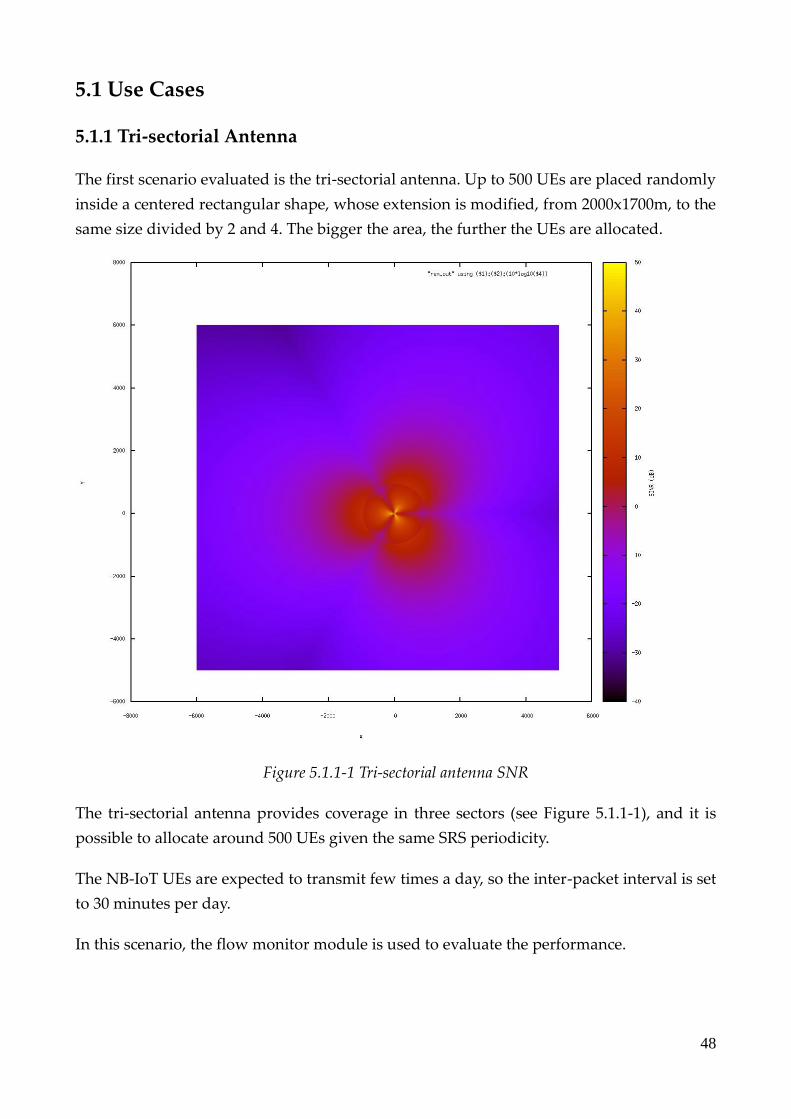
48
5.1 Use Cases
5.1.1 Tri-sectorial Antenna
The first scenario evaluated is the tri-sectorial antenna. Up to 500 UEs are placed randomly
inside a centered rectangular shape, whose extension is modified, from 2000x1700m, to the
same size divided by 2 and 4. The bigger the area, the further the UEs are allocated.
Figure 5.1.1-1 Tri-sectorial antenna SNR
The tri-sectorial antenna provides coverage in three sectors (see Figure 5.1.1-1), and it is
possible to allocate around 500 UEs given the same SRS periodicity.
The NB-IoT UEs are expected to transmit few times a day, so the inter-packet interval is set
to 30 minutes per day.
In this scenario, the flow monitor module is used to evaluate the performance.
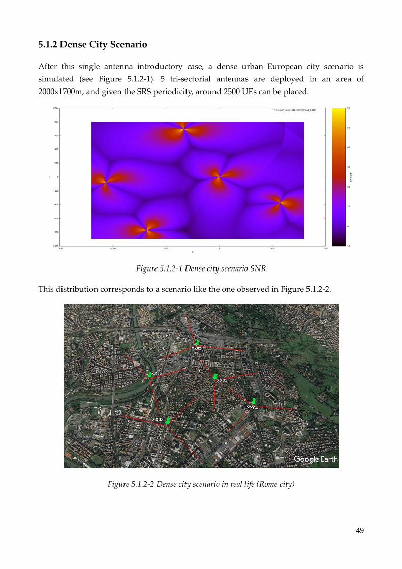
49
5.1.2 Dense City Scenario
After this single antenna introductory case, a dense urban European city scenario is
simulated (see Figure 5.1.2-1). 5 tri-sectorial antennas are deployed in an area of
2000x1700m, and given the SRS periodicity, around 2500 UEs can be placed.
Figure 5.1.2-1 Dense city scenario SNR
This distribution corresponds to a scenario like the one observed in Figure 5.1.2-2.
Figure 5.1.2-2 Dense city scenario in real life (Rome city)

50
Three types of UEs are implemented:
• Type A, with an inter-packet interval time of 24 hours.
• Type B, with an inter-packet interval time of 2 hours.
• Type C, with an inter-packet interval time of 1 hour.
Four UE types of distribution cases are considered:
• Fair Distribution with 30%-40%-30%
• Type A Predominance with 80%-10%-10%
• Type B Predominance with 10%-80%-10%
• Type C Predominance with 10%-10%-80%
As explained in the NB-IoT section, NB-IoT technology uses repetitions to enhance the
coverage of the network. To analyze the impact of repetitions, the efficiency is computed
after processing of the ns-3 UL RLC traces.
Two schemes have been adopted in order to select the UEs that repeat:
• Selecting the UEs by distance to eNB.
• Selecting the UEs by observing their initial efficiency.
In section 5.2, results of both cases are reported.
5.1.3 Heterogenous Scenario
The aggregation of small cells to a network is a feasible technique to widen the coverage
area. These base stations introduce the heterogeneity concept to the system, being
convenient when it comes to ensure connection on areas that deal with a high path loss [45].
Then, to improve the coverage of the whole system, it is possible to introduce some indoor
base stations (small cells) in the simulation. The indoor base stations coverage and
attachment have been already explained in their own sections.
• Small Cell Aggregation to a Tri-sectorial Antenna
Firstly, we develop a single antenna scenario, placing one single tri-sectorial antenna. 100
UEs are distributed randomly in a 1-kilometer area.
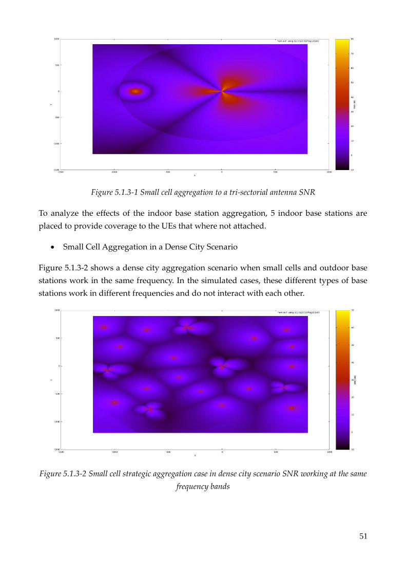
51
Figure 5.1.3-1 Small cell aggregation to a tri-sectorial antenna SNR
To analyze the effects of the indoor base station aggregation, 5 indoor base stations are
placed to provide coverage to the UEs that where not attached.
• Small Cell Aggregation in a Dense City Scenario
Figure 5.1.3-2 shows a dense city aggregation scenario when small cells and outdoor base
stations work in the same frequency. In the simulated cases, these different types of base
stations work in different frequencies and do not interact with each other.
Figure 5.1.3-2 Small cell strategic aggregation case in dense city scenario SNR working at the same
frequency bands

52
Figure 5.1.3-3 Small cell strategic aggregation case in dense city scenario SNR working at different
frequency bands
5.2 Results
5.2.1 Tri-sectorial antenna
Firstly, the performance of a tri-sectorial antenna is evaluated with the ns-3 flow monitor
module. Figure 5.2.1-1 presents the weighted efficiency in the presence of diverse number
of UEs, by changing the area in which UEs are placed:
Figure 5.2.1-1 Tri-sectorial antenna weighted efficiency ratio
0 100 200 300 400 500 600
0
0,2
0,4
0,6
0,8
1
1,2
FLOW MONITOR PERFORMANCE RECEIVED/TRANSMIT BYTES
scenario
scenario/2
scenario/4
Number of UEs

53
After the scenario was systematically reproduced with different number of UEs, it can be
concluded that the wider the area, the less UEs are attached (see Table 5.2.1-1), diminishing
the weighted efficiency ratio.
Area/4 478
Area/2 473
Area 416
Table 5.2.1-1 Attached UEs
In the smaller placement area, the efficiency ratio tends to decrease when placing more and
more UEs. This tendency is not observed with the 2000x1700m full area, as the network is
not congested.
5.2.2 Dense City Scenario
5.2.2.1 Selecting Repeating UEs by Distance
After this preliminary analysis with the flow monitor module, the RLC traces with MATLAB
processing have been adopted.
With the three mentioned different types of UEs (A, B, and C), two types of distributions are
studied, the Fair Case and the Predominance A one.
As NB-IoT implements repetitions, we arbitrarily define a Coverage Extension (CE) area of
640 meters. UEs having a distance larger than this threshold repeat. In this case, only class
A devices can repeat.
Three study cases are presented, with different packet sizes and number of repetitions:
The first study case presents a packet size of 20 bytes and 32 repetitions.

54
In the second case, a larger packet size of 160 bytes is presented, with 4 repetitions.
Figure 5.2.2.1-1 Unweighted efficiency ratios, selecting UEs by distance
In the small packet and high repetitions case, the unweighted efficiency of the
Predominance A distribution is higher than in the Fair Case, as with a smaller packet size,
UEs benefit from the repetitions in class A devices, that only transmit once a day.
On the contrary, in the second case, with big packets and small repetitions, the tendency
varies: when the packet size is larger, too many class A repeating UEs leads to increase the
congestion in the network, that does not benefit as much from signal repetitions as in the
Fair Case.
5.2.2.2 Selection of Repeating UEs by Performance
The next case study focuses on the effect of repetitions on the efficiency.
To select the threshold of repeating UEs, a CDF graph, and arbitrary selected that UEs with
an efficiency less than 95% repeat.
0,9880,989
0,990,9910,9920,9930,9940,9950,996
0,9907
0,995
0,9922
0,9957
0,99180,9908
Unweighted Efficiency Ratio

55
Figure 5.2.2.2-1 CDF of efficiency in case of Class Fairness distribution (no repetition)
The packet size is fixed to 20B, with 32 repetitions, and all four UEs distributions are
simulated. In this case, UEs that repeat are selected between all types of UEs (A, B, C),
among the ones that present a lower initial efficiency.
Figure 5.2.2.2-2 Manual selection of repeating UEs, with small packets and high number of
repetitions unweighted efficiency ratio results

56
Varying the percentage of repeating UEs, the efficiency ratio is modified (see Figure 5.2.2.2-
1).
Implementing repetitions, the efficiency improves. As can be observed in Figure 5.2.2.2-1,
the Predominance A case has higher values than the others, as the network is less congested.
The network performance is also studied when the packet size is of 160B and the number of
repetitions is reduced to 4.
Figure 5.2.2.2-3 Manual selection of repeating UEs, with big packets with high number of
repetitions, unweighted efficiency ratio results
The tendency in this big packet size and low number of repetitions is similar than the
previous one but with Predominance A and Predominance B showing worse results.
In the case of class B Predominance, the bad performance can be explained because of the
randomicity of the simulator, while on class A Predominance, the bad performance is
explained because of too reduced simulation time. As the packets are big and class A only
sends one packet, some class A UEs do not achieve the communication in the given time.
This misleading result can be simply solved by running such scenario on a longer simulation
time.

57
5.2.3 NB-IoT with Heterogenous Architecture
5.2.3.1 Small Cell Aggregation to a Tri-sectorial Antenna
Figure 5.2.3.1-1 show the effect of introducing small cells within the coverage of a single
outdoor base station.
Figure 5.2.3.1-1 Efficiency ratios for small cell aggregation to a tri-sectorial antenna
By introducing 5 small cells, the unweighted efficiency is very similar, but a significant improved of
the weighted efficiency can be observed. This is mainly due to the fact that the introduction of small
cells allows a higher number of UEs to be connected.
As this area is too small, the introduction of more small cells produces an interference that
should be avoided.
5.2.3.2 Small Cell Aggregation to a Dense City Scenario
Figure 5.2.3.2-1 shows the effect of introducing 15 small cells in a regular dense city scenario.
Figure 5.2.3.2-1 Efficiency ratios for small cell aggregation in a dense urban city scenario
Unweighted efficiency ratio 1
tri-sectorial antenna
Weighted efficiency ratio
per 1 tri-sectorial antenna
Unweighted efficiency ratio 1
tri-sectorial antenna and 5
small cells
Weighted efficiency ratio
per 1 tri-sectorial antenna and 5
small cells
0,80,820,840,860,88
0,90,920,940,960,98
0,9761
0,8687
0,9715
0,8938
Weighted and unweighted efficency ratios

58
It can be observed that as in the previous case, the unweighted efficiency tends to be similar,
while weighted indicator significantly improves. This represents an enhancement in the
coverage of the network, as when the number of aggregated antennas increases from one to
fifteen, the number of attached UEs grow from 1533 to 1653.
It is worth mentioning that for poor coverage zones or even for critical applications, small
cell aggregation can be very beneficial.

59
5 Conclusions and Future Works
This thesis presented an analysis on the recent NB-IoT technology and proposed a
framework to evaluate its performance considering different networks and parameters.
The first chapter provided a brief overview of the IoT landscape, introducing the concepts
of mMTC and smart environments. The architecture and requirements of an MTC network,
and the plethora of smart environments have been emphasized.
The second chapter presented and compared commonly adopted solutions to tackle the
demand of massive IoT connectivity. LPWAN networks were explained, and both
unlicensed and licensed solutions were compared.
After studying the suitability of NB-IoT cellular technology, the third chapter expounds
legacy NB-IoT technology LTE and LTE-A, as they are necessary to comprehend the NB-IoT
standard. Then, NB-IoT is deeply explained.
The fourth chapter, regarding Network Simulator-3, summarizes the modules and
modifications that have been used or introduced in ns-3 code, along with an explanation of
the different channel models, base stations, and some attachment considerations.
The last chapter, presents and analyzes the results of different simulation scenarios, from
simple deployments to a complex dense urban city case. The RLC layer traces post-
processing and analysis is also detailed. It is exposed the trade-off between the number of
repetitions in the uplink, and the performance of the network due to congestion, depending
on the size of the packets, UEs interval of transmissions, and number of repetitions. The
aggregation of small cells solution is also presented, with a proof-of-concept that this
method can enhance the network coverage.
More advanced scenarios are under study and analysis, in particular regarding the small
cell aggregation concept.
With a more general perspective, that exceeds the possibilities of this thesis, there is a lot of
work to be done by researchers in the IoT topic. Because of the ns-3 open source project
nature, the simulator must be extended and developed continuously. Coexistence projects
like LAA-Wi-Fi-Coexistence should be tested and developed in the future. Even regarding
NB-IoT is close to LTE, a specific NB-IoT module creation should is helpful to the technology
testing, improving the reliability and standardization of the simulations.
Also, as cellular operators are already deploying their NB-IoT networks since early 2018, a
fluent communication with these companies should be strongly pursued.

60
Budget
The software used in the project is open source, unless MATLAB, with a cost of 500 euros
for educational institutions like Sapienza di Roma or Polytechnic University of Catalonia.
Author dedication to the project was around 25 hours per week, for approximately 20 weeks
of project, resulting in 500 hours in total. Considering 10 euros per hour retribution, the
authors total retribution for this project would be around 5000 euros. Thesis supervisor and
co-supervisor retributions are not considered.
During the project, seven different computers have been used because of the thesis
computational requirements. The cost of the computers is close to 10000 euros.
The total cost of the project considering the previous mentioned resources is approximately
around 15500 euros.
Concerning the financial viability, the ACTS Laboratory at DIET, that is the research group
laboratory where the project was carried out, is publicly funded by the Italian Ministry of
Education for the University and Research (Ministerio dell’Instruzione dell’Università e della
Ricerca). Furthermore, it is supported by a team of cooperating industrial partners.

61
References
[1] Ashton, Kevin. "That ‘internet of things’ thing." RFiD Journal 22.7 (2011)
[2] Statista, “IoT connected devices installed base worldwide from 2015 to 2025 (billions)“,
https://www.statista.com/statistics/471264/iot-number-of-connected-devices-worldwide,
October 2017
[3] Amy Nordrum, “Popular IoT forecast of 50 billion devices by 2020 is
outdated“,https://spectrum.ieee.org/tech-talk/telecom/internet/popular-internet-of-things-
forecast-of-50-billion-devices-by-2020-is-outdated, (Consulted November 2017)
[4] Kushalnagar, Nandakishore, Gabriel Montenegro, and Christian Schumacher. IPv6 over
low-power wireless personal area networks (6LoWPANs): overview, assumptions, problem statement,
and goals. No. RFC 4919. (2007)
[5] Taleb, Tarik, and Konstantinos Samdanis. "Ensuring service resilience in the EPS: MME
failure restoration case." Global Telecommunications Conference (GLOBECOM 2011), 2011 IEEE.
IEEE, (2011)
[6] Taleb, Tarik, and Andreas Kunz. "Machine type communications in 3GPP networks:
potential, challenges, and solutions." IEEE Communications Magazine 50.3 (2012)
[7] ETSI, Machine-to-Machine communications (M2M); M2M service requirements, ETSI TS
102 689 V2.1.1 (2013-07)
[8] Perumal, Thinagaran, et al. "Proactive architecture for Internet of Things (IoTs)
management in smart homes." Consumer Electronics (GCCE), 2014 IEEE 3rd Global Conference
on. IEEE, (2014)
[9] Goto, Teiyu. "Electronic control unit." U.S. Patent No. D448,810. 2 Oct. (2001)
[10] Shrouf, Fadi, Joaquin Ordieres, and Giovanni Miragliotta. "Smart factories in Industry
4.0: A review of the concept and of energy management approached in production based on
the Internet of Things paradigm." Industrial Engineering and Engineering Management (IEEM),
2014 IEEE International Conference on. IEEE, (2014)
[11] Zanella, Andrea, et al. "Internet of things for smart cities." IEEE Internet of Things
journal 1.1 (2014)
[12] Zheng, Jixuan, David Wenzhong Gao, and Li Lin. "Smart meters in smart grid: An
overview." Green Technologies Conference, 2013 IEEE. IEEE, (2013)
[13] Alejandro, Lisa, et al. "Global market for smart electricity meters: Government policies
driving strong growth." Washington, DC: US International Trade Commission, Off. of
Industries (2014)

62
[14] Rappaport, Theodore S. Wireless communications: principles and practice. Vol. 2. New
Jersey: prentice hall PTR, (1996)
[15] Park Associates, “Top 10 IoT Consumer Trends in 2017”, Parks Associates, (2017)
[16] 3GPP, http://www.3gpp.org/about-3gpp/about-3gpp (Consulted November 2017)
[17] ETSI, http://www.etsi.org/standards (Consulted November 2017)
[18] IEEE, https://www.ieee.org/index.html (Consulted November 2017)
[19] IETF, https://www.ietf.org/about/ (Consulted November 2017)
[20] SIGFOX, https://www.sigfox.com/en/sigfox-iot-technology-overview, (Consulted
November 2018)
[21] Raza, Usman, Parag Kulkarni, and Mahesh Sooriyabandara. "Low power wide area
networks: An overview." IEEE Communications Surveys & Tutorials 19.2 (2017)
[22] SIGFOX, “M2M and IoT redefined through cost effective and energy optimized connectivity”
[23] Alliance, LoRa. "Mobile Experts White Paper for." (2016).
[24] Weightless, “” Weightless” a new M2M/IoT cellular technology”
[25] Real Wireless, “A Comparison of UNB and Spread Spectrum Wireless Technologies as used in
LPWA M2M Applications” (2015)
[26] Ratasuk, Rapeepat, et al. "Narrowband LTE-M system for M2M
communication." Vehicular Technology Conference (VTC Fall), 2014 IEEE 80th. IEEE, (2014)
[27] Dawaliby, Samir, Abbas Bradai, and Yannis Pousset. "In depth performance evaluation
of LTE-M for M2M communications." The 12th IEEE International Conference on Wireless and
Mobile Computing, Networking and Communications, WiMob'16. (2016)
[28] Yang, Wenjie, et al. "Narrowband Wireless Access for Low-Power Massive Internet of
Things: A Bandwidth Perspective." IEEE Wireless Communications (2017)
[29] Agilent Technologies, “LTE and the Evolution to LTE-Advanced Fundamentals”, (2017)
[30] Tutorialspoint, “LTE network architecture “,
https://www.tutorialspoint.com/lte/lte_network_architecture.htm,(Consulted December
2017)
[31] Fischer, Patrick. "Method of setting up connections in a mobile radio system." U.S.
Patent Application No. 10/839,173
[32] 3GPP, http://www.3gpp.org/technologies/keywords-acronyms/97-lte-advanced,
(Consulted December 2017)
63
[33] Nee, Richard van, and Ramjee Prasad. OFDM for wireless multimedia communications.
Artech House, Inc., (2000)
[34] Holma, Harri, and Antti Toskala, eds. LTE for UMTS-OFDMA and SC-FDMA based radio
access. John Wiley & Sons, (2009)
[35] Gesbert, David, et al. "From theory to practice: An overview of MIMO space-time coded
wireless systems." IEEE Journal on selected areas in Communications 21.3 (2003)
[36] Dahlman, Erik, Stefan Parkvall, and Johan Skold. 4G: LTE/LTE-advanced for mobile
broadband. Academic press, (2013)
[37] Mangalvedhe, Nitin, Rapeepat Ratasuk, and Amitava Ghosh. "NB-IoT deployment
study for low power wide area cellular IoT." Personal, Indoor, and Mobile Radio
Communications (PIMRC), 2016 IEEE 27th Annual International Symposium on. IEEE, (2016)
[38] Beyene, Yihenew Dagne, et al. "NB-IoT technology overview and experience from
cloud-RAN implementation." IEEE wireless communications 24.3 (2017)
[39] Wang, Y-P. Eric, et al. "A primer on 3gpp narrowband internet of things." IEEE
Communications Magazine 55.3 (2017)
[40] Ratasuk, Rapeepat, et al. "NB-IoT system for M2M communication." Wireless
Communications and Networking Conference (WCNC), 2016 IEEE. IEEE, (2016)
[41] Adhikary, Ansuman, Xingqin Lin, and Y-P. Eric Wang. "Performance evaluation of NB-
IoT coverage." Vehicular Technology Conference (VTC-Fall), 2016 IEEE 84th. IEEE, (2016)
[42] B. Schulz, “Narrowband Internet of Things Measurements”. Rhode and Schwarz White
Paper, (2016)
[43] Keysight Technolgoies, “CAT-M & NB-IoT Design and Conformance Tests”, (2017)
[44] Kita, Naoki, Wataru Yamada, and Akio Sato. "Path loss prediction model for the over‐
rooftop propagation environment of microwave band in suburban areas." Electronics and
Communications in Japan (Part I: Communications) 90.1 (2007)
[45] Jungnickel, Volker, et al. "The role of small cells, coordinated multipoint, and massive
MIMO in 5G." IEEE Communications Magazine 52.5 (2014)
64
List of Abbreviations
2G Second Generation
3G Third Generation
3GPP Third Generation Partnership Project
4G Fourth Generation
5G Fifth Generation
AC Alternating Current
ACK Acknowledgment
AM Amplitude Modulation
AR Augmented Reality
AWGN Additive White Gaussian Noise
CA Carrier Aggregation
CDD Cyclic Delay Diversity
CDMA Code Division Multiple Access
CE Coverage Extension
CFO Carrier Frequency Offset
CoMP Coordinated Multi-Point
CP Cyclic Prefix
CQI Channel Quality Indicator
CSMA Carrier Sense Multiple Access
DC Direct Current
DCI Downlink Control Information
DFT Discrete Fourier Transform
DL Downlink
DPC Downlink Physical Channel
DRS Demodulation Reference Signal
DRS Downlink Reference Signal
DRX Discontinuous Reception
EARFCN EUTRA Absolute Radio-Frequency Channel Number
ECU Electronic Control Units
eMIMO enhanced Multiple Input Multiple Output
eMTC enhanced Machine Type Communications
eNB enhanced NodeB
EPC Evolved Packet Core
ERP Effective Radiated Power
EU European Union
eUTRAN Evolved Terrestrial Radio Access Network

65
FDD Frequency Division Duplexing
FDMA Frequency Division Multiple Access
FFT Fast Fourier Transform
GSM Global System for Mobile communications
HeNB Home enhanced NodeB
HFC Hybrid Fiber-Coaxial
HSPA High-Speed Packet Access
HSS Home Subscriber Service
ICIC Inter-Cell Interference Coordination
ICT Information and Communication Technology
IDE Integrated Developer Environment
IEEE Institute of Electric and Electronic Engineers
IoT Internet of Things
IP Internet Protocol
ISI Inter Symbol Interference
ISM Industrial, Scientific, Medical
ITU International Telecommunication Union
IUI Inter-User Interference
LOS Line of Sight
LPWAN Low Power Wide Area Network
LTE Long Term Evolution
LTE-A Long Term Evolution Advanced
LTN Low Throughput Network
M2M Machine-to-Machine Communications
MAC Medium Access Control
MAN Metropolitan Area Network
MCL Maximum Coupling Loss
MIB Master Information Block
MIMO Multiple Input Multiple Output
MME Mobility Management Entity
MMTC Massive Machine Type Communications
MT Mobile Termination
MTC Machine Type Communications
NACK Non-Acknowledgement
NB Narrow Band
NB-IoT Narrow-Band Internet of Things
NB-PBCH Narrow-Band Physical Broadcast Channel
NB-PDCCH Narrow-Band Physical Downlink Control Channel

66
NB-PDSCH Narrow-Band Physical Downlink Shared Channel
NB-RS Narrow-Band Reference Signal
NLOS Non-Line of Sight
NOMA Non-Orthogonal Multiple Access
NS Network Simulator
OFDMA Orthogonal Frequency Division Multiple Access
PAPR Peak to Average Power Ratio
PDCP Packet Data Convergence Protocol
PGW Packet Data Network Gateway
PHICH Physical Hybrid-ARQ Indicator Channel
PHY Physical layer
PLC Power Line Carrier
PRACH Physical Random-Access Channel
PRB Physical Resource Block
PRM Precoding Matrix Information
PSD Power Spectral Density
PSS Primary Synchronization Signal
PUCCH Physical Uplink Control Channel
PUSCH Physical Uplink Shared Channel
QoS Quality of Service
QPSK Quaternary Phase Shift Keying
RAN Radio Access Network
RB Resource Block
RF Radio Frequency
RLC Radio Link Control
RN Relay Nodes
RRC Radio Resource Control
RRC Radio Resource Control
RU Resource Unit
RX Reception
SC Single Carrier
SC-FDMA Single Carrier-Frequency Division Multiple Access
SDO Standard Developing Organization
SGW Serving Gateway
SIG Special Interest Group
SIM Subscriber Identity Module
SINR Signal to Interferent-Noise Ratio
SM Spatial Multiplexing

67
SNR Signal to Noise Ratio
SR Scheduling Requests
SRS Sounding Reference Signal
SS Spread Spectrum
SS Synchronization Signal
SSS Secondary Synchronization Signal
TB Transport Block
TBCC Tail-Biting Convolutional Coding
TC Turbo Coding
TCP Transmission Control Protocol
TDD Time Division Duplexing
TDMA Time Division Multiple Access
TE Terminal Equipment
TM Transmission Modes
TX Transmission
UCI Uplink Control Information
UE User Equipment
UICC Universal Integrated Circuit Card
UL Uplink
UMTS Universal Mobile Telecommunication System
UNB Ultra-Narrow Band
US United States
USIM Universal Subscriber Identity Module
UWB Ultra-Wide Band
VR Virtual Reality
WAN Wide Area Network
WB Wide Band
WiMAX Worldwide Interoperability for Microwave Access
WLAN Wireless Local Area Network
WPAN Wireless Personal Area Network
WRAN Wireless Regional Area Network
DSL Digital Subscriber Line

68
List of Tables
Table 1.1-1 Main technologies involved in IoT ......................................................... 8
Table 1.2-1 mMTC and critical MTC networks comparison .................................. 9
Table 2.4-1 LPWAN technologies comparison ....................................................... 22
Table 3.1-1 Generation term evolution .................................................................... 23
Table 3.3.2-1 NB-IoT main features .......................................................................... 36
Table 3.3.3-1 NB-IoT physical channels ................................................................... 47
Table 5.2.1-1 Attached UEs ........................................................................................ 53
List of Figures
Figure 1.2.4.1-1 Architecture of an MTC network ................................................. 12
Figure 2.4-1 Bandwidth trade-off ............................................................................. 21
Figure 3.1.2-1 LTE network architecture ................................................................. 24
Figure 3.1.2-3 LTE base station ................................................................................. 25
Figure 3.1.2-4 Evolved Packet Core architecture .................................................... 26
Figure 3.1.3-1 LTE Protocol Stack scheme ............................................................... 27
Figure 3.1.5.1-1 OFDM symbol generation ............................................................. 28
Figure 3.1.5.1-2 LTE FDD frame structure .............................................................. 28
Figure 3.1.5.1-3 LTE TDD frame structure .............................................................. 29
Figure 3.1.5.2-1 OFDMA and SC-FDMA pre-coding scheme comparison ........ 30
Figure 3.1.5.2-2 OFDMA and SC-FDMA carrier comparison with QPSK mod. 30
Figure 3.3.1-1 NB-IoT operation modes ................................................................... 35
Figure 3.3.5.1-1 LTE and NB-IoT interference scheme .......................................... 39
Figure 4.4.1-1 Indoor base station SNR.................................................................... 45
Figure 4.4.2-1 Outdoor base station SNR ................................................................ 45
Figure 4.4.3-1 C++ attachment code ......................................................................... 46
Figure 5.1.1-1 Tri-sectorial antenna SNR ................................................................. 48
Figure 5.1.2-1 Dense city scenario SNR ................................................................... 49
Figure 5.1.2-2 Dense city scenario in real life (Rome city) .................................... 49
Figure 5.1.3-1 Small cell aggregation to a tri-sectorial antenna SNR .................. 51
Figure 5.1.3-2 Small cell strategic aggregation case in dense city scenario SNR
working at the same frequency bands ..................................................................... 51
Figure 5.1.3-3 Small cell strategic aggregation in dense city scenario SNR
working in different frequency bands ..................................................................... 52
Figure 5.2.1-1 Tri-sectorial antenna weighted efficiency ratio ............................ 52
Figure 5.2.2.1-1 Unweighted efficiency ratios, selecting UEs by distance .......... 54

69
Figure 5.2.2.2-1 CDF of efficiency in case of Class Fairness distribution
(no repetition) .............................................................................................................. 55
Figure 5.2.2.2-2 Manual selection of repeating UEs, small packets and high
number of repetitions unweighted efficiency ratios .............................................. 55
Figure 5.2.2.2-3 Manual selection of repeating UEs, big packets and small
number of repetitions unweighted efficiency ratios ............................................. 56
Figure 5.2.3.1-1Efficiency ratios for small cell aggregation to a tri-sectorial
antenna ......................................................................................................................... 57
Figure 5.2.3.2-1Efficiency ratios for small cell aggregation to a dense city
scenario ......................................................................................................................... 57