analysis of the intel 386 and i486 microprocessors for the ... technical memorandum 103862 analysis...
TRANSCRIPT

NASA Technical Memorandum 103862
Analysis of the Intel 386 andi486 Microprocessors for theSpace Station Freedom DataManagement System
Yuan-Kwei Liu
(NA_A-TM-I03862) ANALYSIS OF THE INTEL 386
AND i48& MICkOPROCESSORS FOR THE SPACE
STATION FREEOQM OATA MANAGEMENT SYSTEM
(NASA) 24 p CSCL 09B
G3/02
N_I-25687
Unclas
0020605
May 1991
NASANational Aeronaut;cs andSpace Administration
https://ntrs.nasa.gov/search.jsp?R=19910016373 2018-05-14T22:52:14+00:00Z


NASA Technical Memorandum 103862
Analysis of the lntel 386 andi486 Microprocessors for theSpace Station Freedom DataManagement SystemYuan-Kwei Liu, Ames Research Center, Moffett Field, California
May 1991
NationalAeronautics andSpace Administration
Ames Research CenterMoffett Field, California 94035-1000


1. SUMMARY
This report analyzes the feasibility of upgrading the Intel 386 a microprocessor, which has
been proposed as the baseline processor for the Space Station Freedom (SSF) Data Management
System (DMS), to the more advanced i486 a microprocessor. It is part of an effort funded by the
National Aeronautics and Space Administration (NASA) Space Station Freedom Advanced
Development program.
The items compared between the two processors include the instruction set architecture,
power consumption, the MIL-STD-883C Class S (space) qualification schedule, and performance.
The advantages of the i486 over the 386 are lower power consumption and higher floating-
point performance in speed. The i486 on-chip cache, however, has neither parity check nor error
detection and correction circuitry. In space, the probability of having the contents of the cache
altered, is higher than on the ground due to the higher radiation exposure. Therefore, it is
necessary to measure the performance of the i486 with the cache disabled.
The i486 with on-chip cache disabled, however, has lower integer performance in speed than
the 386 without cache, which is the current DMS design choice. Using external cache with a
specially designed cache controller can improve the performance of the i486, but the added
complexity may not provide a better solution than adding cache to the 386.
The benchmark performance of a 386-based prototype Flight Equivalent Unit (FEU), which is
the closet configuration to the DMS design as of April 1991, is only about 50% of a PS/2 Model
70 with cache, which is generally considered as a 4 MIPS (million instructions per second)
computer. Adding cache to the 386/387 DX memory hierarchy appears to be the most beneficial
way to enhance computation-intensive performance for the current DMS design at this time.
a 386, 387 and i486 are trademarks of lntel Corporation.
3
PRLnCEDING .PAGE BLANK NOT F!L_ED

2. OVERVIEW OF INTEL 386 AND i486 MICROPROCESSORS
2.1. lntel 386 Microprocessor
Intel's 80xxx family of microprocessors was initiated with the 16-bit 8086 processor in 1978.
Intel then developed the 8088 which has a 16-bit internal architecture with an 8-bit data bus
interface. The 8088 was chosen by IBM (International Business Machines Corporation) for use in
the IBM PC (personal computer) in 1982. The 8087 floating-point coprocessor adds arithmetic,
trigonometric, exponential, and logarithmic instructions to the 8086, 8088, 80186, and 80188
instruction set. The 80xxx instruction set architecture (ISA) is upward compatible as each new
ISA remains a super set of the previous ISA as more instructions are added. Figure 1 shows the
relationship among these processors.
1486_DXH4861 SX ]
1386 DX _'-q 386 SX _ 386 SL [ 1387 DX H 387 SX [I I
80286 I 180287 ]
iI 80186 H 80188 I1
[ 8086 H 8088 ] [ 8087 ]
Central Processors Floating-Point Coprocessors
FIGURE 1. The Intel 80xxx Microprocessor Family Tree
The 386 family of microprocessors includes the 386 DX, 386 SX, and 386 SL processors.
The 386 DX is a full 32-bit processor. The 386 SX and SL have 32-bit internal architectures with
a 16-bit data bus interface. The 386 DX and 387 DX (floating-point coprocessor) are the baseline
embedded processors for the standard data processor (SDP) of the Space Station Freedom (SSF)
Data Management System (DMS), Electrical Power System 0_PS), and other systems. The 386
SX and 387 SX are baselined for the multiplexer-demultiplexer (MDM) of the SSF. In this
analysis only the 386 DX and 387 DX were used.
The 386 DX has eight general-purpose 32-bit registers. The instruction set offers 8-, 16-, and
32-bit data types (ref. 1). It addresses 4 gigabytes (232) of memory and has an on-chip memory
management unit (MMU) that supports virtual memory management. The commercial 386 DX
processors are available at clock rates of 20, 25, and 33 MHz as of April 1991. The corresponding
internal bus bandwidths are 40, 50, and 66 megabytes per second.
The 386 DX has three modes of operation: (1) virtual 8086 mode, which enables the
processor to multi-task standard DOS (Disk Operating System) applications; (2) real address mode
4

(real mode), in which the 386DX behaveslike an 8088/8086,with the original 640-Kbyte/1-Mbyte limitations;and(3)protectedvirtual addressmode(protectedmode),in which the386DXcanexecutemultiple programsconcurrentlywith eachprogrambeing protected(ref. 2). Theprotectedmodeutilizes thefull capacitiesof the386DX, suchasthevirtual memoryaddressingandmultitasking,whichallowsmultipleprogramsto executeconcurrently.
Therearefourprivilegelevelsin theprotectedmode,from level0 through3. Theseprivilegelevelsarediscussedin detail in Section4.3.
The387DX floating-pointcoprocessoris designedto workwith the386DX. The387DX iscompliantwith theANSI/IEEE 754-1985floating-point standard.It expandsthe 386DX datatypesto include32-,64-,and80-bitfloating-point,and32-,and64-bit integers.ThecurrentDMSdesignusesthe387DX coprocessor.
2.2. Intel i486 Microprocessor
The i486 is a full 32-bit microprocessor which is currently the top-of-the-line processor in the
Intel 80xxx family. The on-chip integration of the i486 includes an 8-Kbyte cache, a floating-point
unit (FPU), and a paged, virtual memory management unit (ref. 3). The i486 supports
multiprocessor instructions, cache consistency protocols, second level cache, and other
multiprocessor support hooks. The i486 ISA is upward compatible with the 386/387 DX ISA with
six more instructions added. The commercial i486 chips are available at clock rates of 25 and 33
MHz as of April 1991.
The i486's on-chip cache uses a write-through memory update policy, i.e., the information is
written to both the cache and the main memory. The advantages of this (as compared to write-
back) are that main memory is always up to date and the memory logic design is simpler. The
disadvantage of the policy is increased bus traffic. The on-chip cache is fundamental to achieving
the higher performance level of the 80xxx family and is discussed in detail in Sections 4.1. and
4.2.
Although the 8-Kbyte cache is considerably smaller than the 64- and 128-Kbyte external
caches built into many 386-based PCs, it is considerably more sophisticated. Because of the small
cache size and write-through memory policy, Intel has introduced external second-level caches to
improve the i486 performance.

3. COMPUTER CONFIGURATION FOR THE COMPARISON
3.1. Hardware Configuration
The hardware configuration used for this comparison included a commercial IBM PS/2 b
Model 70-A21 computer, which has an Intel 386 DX processor. An Intel 387 DX floating-point
coprocessor was added to the computer. The clock rate of the computer was 25 MHz. The PS/2
comes with 64-kilobyte (KB) of cache memory and 2-megabyte (MB) of main memory. An
additional 2 MB of main memory was added to the PSI2. The proposed DMS design includes 20-
MHz 386 DX and 387 DX processors and 4 MB of main memory. The cache is not included in
the current DMS design. A summary of the PS/2 and other configurations are shown in Table 1.
Items
ii ,i
Microprocessors
Clock
External cache
Internal cachei11 ii i1_
Main memory
Error correctioncodes
Single event
upset scrub
Operating system
Comp!ler
Benchmark 1
Benchmark 2
...... TABLE 1. Summary of confi_:urations
PS/2
Model 70
Prototype
EDP
Prototype
FEU
386 and 387 DX i486 386 and 387 DX 386 and 387 DX
25 MHz 25 MHz 20 MHz 20 MHz
64 KB N/A N/A N/A
NIA
8 KB
4MB
N/A
N/A
Lyn_xOS (v 1.2)
Lynx C
Dhrystone
Whetstone
N/A, w,
LynxOS. (v 1.2)
Lynx C
N/A
4MB, , , ,,,
N/A
N/A
LynxOS (.v 2.0)
Lynx C
Dhrystone
Whetstone
Dhrystone
Whetstone
N/A
4 MB
Yes
Yes
LynxOS (v 2.0)
Lynx C
Dhrystone
Whetstone
As of April 1991, the Model 70-A21 was the only PSI2 model that can be upgraded to the
i486. To upgrade the processor, an IBM PS12 486125 Power Platform (a board containing a 25-
MHz i486 processor), was used to swap with the 3861387 DX board.
In addition to the commercial PSI2 computer, two additional configurations which are closer
to the DMS flight design were also used for the performance comparison: a prototype EDP
b PSf2 is a registered trademark of International Business Machine Corporation.
6

(EmbeddedDataprocessor)andanprototypeFEU (FlightEquivalentUnit). Theconfigurationofthe prototypeEDP is similar to thePS/2Model 70 exceptfor theclock speedandtheexternalcache.TheprototypeFEU is theclosetconfigurationto theDMS designasof April 1991:it hasno cachememory, but it hasECC (Error CorrectionCodes)and singleeventupset scrubforradiationtolerancein itsmainmemory.
3.2. Software Configuration
LynxOS ¢ is a UnixCl-based real-time operating system. LynxOS, which includes Lynx real-
time operating system kernel and device drivers, has been selected to be used in the DMS. Version
1.2 of LynxOS was used on the PS/2 and version 2.0 was used on the prototype FEU and the
prototype EDP.
The features of LynxOS include (1) deterministic response; (2) pre-emptive kernel; (3) IEEE
(Institute of Electrical and Electronics Engineers) POSIX (Portable Operating System Interface for
Computer Environments) P1003.1 compliance; and (4) contiguous files (ref. 4).
3.3. Benchmark Programs
Benchmark programs are used to measure the performance of a processor and the efficiency of
a compiler. The C version of the Dhrystone (version 2.1) and Whetstone (version 1.0) benchmark
programs were used for this performance comparison. These two benchmarks are synthetic
programs designed to match the average frequency of an operation and operands of a large set of
programs. The Lynx C compiler, which has no optimization option as of April, 1991, was used to
compile the benchmark programs.
The Dhrystone benchmark, which has no floating-point arithmetic operations, is designed to
measure integer performance. The benchmark recommends executing 30,000 cycles on sixteen bit
machines, and many more cycles on faster machines. 100,000 cycles were executed for this
comparison. The results are measured in "Dhrystones per Second," with higher numbers
representing higher performance level.
The Whetstone benchmark is designed to measure a mix of operations typical of scientific
computation. The number of cycles can be set before compilation. In this comparison, 100 cycles
were executed, which translates to 10 million Whetstone instructions. Elapsed time is used to
calculate the results, which are measured in KWlPS (Kilo-Whetstone Instructions Per Second):
e LynxOS is a registered trademark of Lynx Real-Time Systems Inc.
d Unix is a trademark of AT&T Bell Laboratories.
7

WhetstonePerformance(KWIPS) = (10 * 106/Elapsed Time in seconds)/103
- 104 / Elapsed Time
Again, higher numbers denote higher performance levels. The Dhrystone and Whetstone
benchmark results are given in Section 5.4. and examples of the results are shown in Appendix
7.4.

4. THE i486 ON-CHIP CACHE
4.1. The i486 On-Chip Cache Organization
The i486 has an 8 Kbyte on-chip cache. The cache is a unified (or mixed) cache, i.e. it can
contain either instructions or data. The write strategy of the cache is a write-through policy. If the
write was a cache hit, the information is written to both the internal cache and external memory. A
write to an address not contained in the internal cache will only be written to external memory.
The cache organization is 4-way set associative, i.e. there are 4 blocks (lines) in a set (ref. 3).
A block is first mapped onto a set, and then placed anywhere within the set. Each block size is 16
bytes. The 8 Kbyte cache is physically split into four 2-Kbyte caches, each containing 128 blocks
as shown in Figure 2. Associated with each 2-Kbyte cache are 128 21-bit tags.
2116-Byte
"--_Bit[ 4- --_ BlockSizeTag
ID IN ID !
2 KBytes
2 KBytes
I LBlocks
2 KBytes
T128 Sets
12 KBytes I
FIGURE 2. The i486 On-Chip Cache Organization
The i486 on-chip cache, however, has neither parity check nor error detection and correction
circuitry. When the cache is exposed in a high radiation environment, such as the Space Station
Freedom, for a long period of time, a single event upset may occur, i.e. the contents of the cache
memory may be altered. For this reason, it is necessary to measure the performance of the i486
with the cache disabled.
4.2. The i486 On-Chip Cache Controlling Mechanism
The i486 has four 32-bit control registers (CR0, 1, 2 and 3). Bit 30 (CD bit) and bit 29 (NW
bit) in CR0 provide the on-chip cache control. The CD bit enables and disables the cache. The
9
The CD and NW bits define fourNW bit controls memory write-through and invalidates.
operating modes of the cache (ref. 3), which are listed in Table 2.
TABLE 2. The i486 on-chip cache operating modes
CD NW Cache Operating Mode
1 1 Cache fills disabled, write-through and invalidates disabled
1 0 Cache fills disabled, write-through and invalidates enabled
0 1 INVALID. A fault with error code of 0 is raised
0 0 Cache fills enabled, write-through and invalidates enabled
When the CD and NW bits are cleared (CD----0 and NW=0), the cache is in the normal
operating mode. The cache fills, write-through, and invalidates are enabled. The cache can be
completely disabled by setting CD=I and NW=I and then flushing the cache. If the cache is not
flushed, cache hits on reads will still occur and data will be read from the cache.
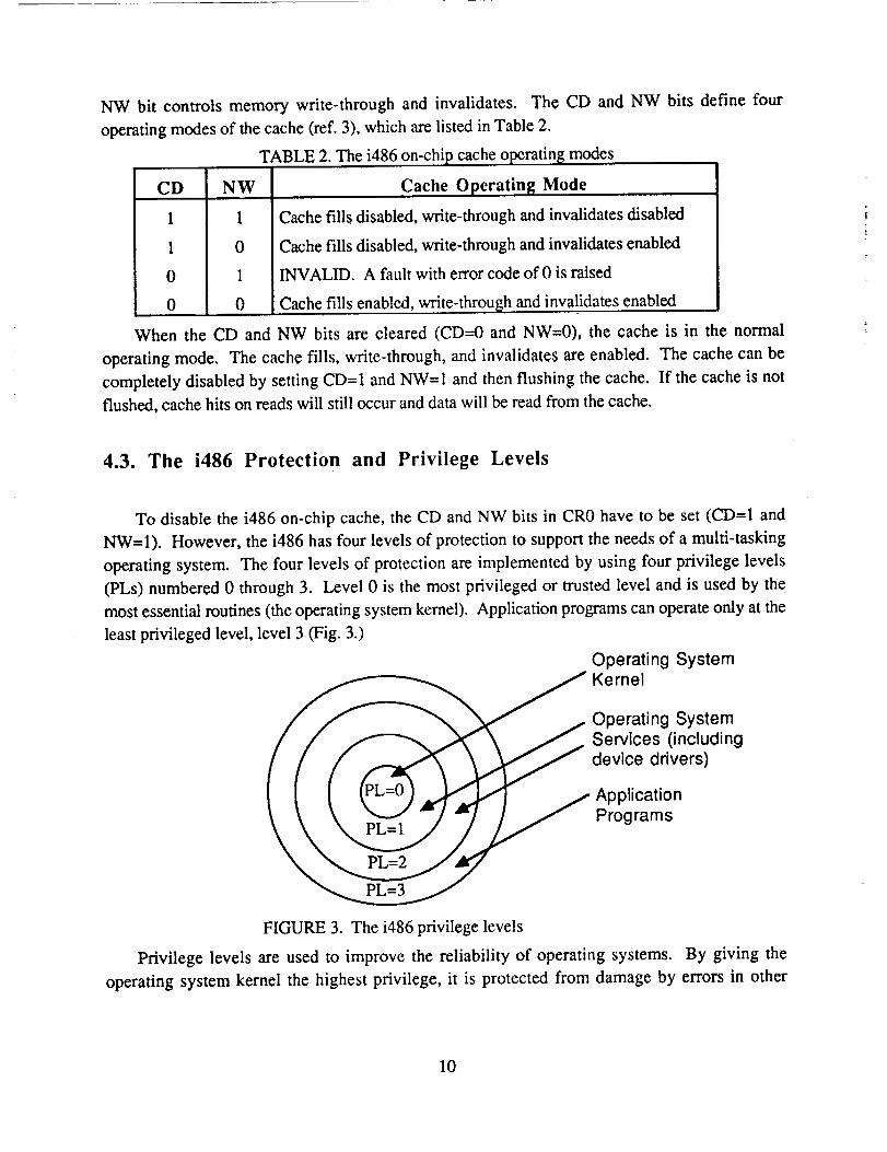
4.3. The i486 Protection and Privilege Levels
To disable the i486 on-chip cache, the CD and NW bits in CR0 have to be set (CD=I and
NW=I). However, the i486 has four levels of protection to support the needs of a multi-tasking
operating system. The four levels of protection are implemented by using four privilege levels
(PLs) numbered 0 through 3. Level 0 is the most privileged or trusted level and is used by the
most essential routines (the operating system kernel). Application programs can operate only at the
least privileged level, level 3 (Fig. 3.)
Operating SystemKernel
Operating System
Services (includingdevice drivers)
Application
Programs
FIGURE 3. The i486 privilege levels
Privilege levels are used to improve the reliability Of operating systems. By giving the
operating system kernel the highest privilege, it is protected from damage by errors in other
10

programs. If an applicationprogramcrashes,the operating system has a chance to generate a
diagnostic message and attempt to recover.
The privilege level determines which instructions from the instruction set can be executed by a
task. Instructions that modify the system registers, such as CR0, are considered privileged
instructions and can be executed only at privilege level 0. Thus, the system registers can be
modified only by the operating system kernel, never by application programs.
4.4. Device Driver to Disable/Enable the i486 On-Chip Cache
Device drivers provide interfaces between an operating system kernel and physical hardware
devices. A device driver has the detail information of a particular device and hides these details
from the operating system kernel. Device drivers are linked with the kernel and become part of the
operating system, such as the Lynx real-time operating system shown in Figure 4. Most of the
code in the LynxOS is implemented in C language, but many device drivers in the LynxOS have
assembly programs. The Lynx Assembler is used to assemble these assemblyembedded
programs.
Applications/Utilities/LibrariesI
Lynx Operating System Kernel
Device Drivers i
t tI Hardware I
FIGURE 4. Lynx operating system organization
LynxOS
To disable/enable the i486 on-chip cache, a device driver was implemented; the complete
program is listed in Appendix 7.1. The main algorithm of the program includes these steps:
• load the contents of CR0 to a general-purpose 32-bit EAX register;
• set bit 29 and 30 of the EAX register to 1 for disabling the cache, or clear the two bits to 0
for enabling the cache;
• store the contents of EAX back to CR0; and
• flush the cache.
The implementation of the main algorithm to disable the i486 on-chip cache is listed in
Table 3.
11

TABLE 3. Mainalgorithmof thedevicedrivertodisablethei486on-chipcachemov EAX, CR0
or EAX, CR0_CD I CRONW
mov CR0, EAX
invd
4.5. Errors Found in the Lynx Assembler
Two errors were found in the Lynx Assembler (version 1.2) when implementing the device
driver to disable/enable the i486 on-chip cache: in storing the content of CR0 to the EAX register
and in loading the contents of EAX to CR0. The main algorithm shown in Table 3 was assembled
incorrectly by the Lynx Assembler and the results are shown in Table 4.
TABLE 4. The incorrect results of the main algorithm assembled by the Lynx Assembler
rnov EAX, 0x0
or EAX, CR0_CD I CR0_NW
mov 0x0, EAX
invd
The instruction "mov EAX, CR0" was used to load the contents of CR0 to EAX. Instead of
loading the contents of CR0 to EAX, the Lynx Assembler actually assembled the instruction as
"mov EAX, 0x0" and loaded 0 (zero) to EAX. When the instruction was executed, there was no
warning or other message indicating the error.
The instruction "mov CR0, EAX" was used to store the contents of EAX back to CR0.
Instead of storing the contents of EAX to CR0, it actually assembled the instruction as "mov 0x0,
EAX" and stored the contents of EAX to address 0 (zero). Again, there was no warning or other
message indicating the error when assembled. When the instruction was executed, however, the
computer shut down e.
4.6. Work Around the Problems
The instructions of a microprocessor come from the instruction set and cause the
microprocessor to execute an operation such as "MOV", "ADD" or "POP". They axe translated by
the assembler into machine language and are standardized across all assemblers. The instructions
are often called "opcodes".
e The above errors were reported to Lynx Real-Time Systems, Inc. in October '90. Lynx RTS has recognized the
problems and will correct them when they deliver the next version of the LynxOS to NASA Johnson Space Center
(JSC) and IBM Federal Sector Division (FSD) in Houston, Texas.
12

Thedirectivesof anassemblerarenotprovidedby themicroprocessorinstructionset. Theyareprovided by individual assemblervendors,suchasthe Microsoft AssemblerandtheLynxAssembler,andcanvary from vendorto vendor. Thedirectivesarenot translatedinto machinelanguage.Instead,theyprovideinstructionsto theassembleritself. Thedirectivesareoftencalled"pseudo-ops"to distinguishthemfrom trueopcodes(ref.5).
The hexadecimalcodesof the two "mov" instructionsare listed in Table 5. The LynxAssemblerversion 1.2 is a 386-basedassemblerand doesnot supportthe i486. However, the"invd" instructionis oneof thesixnewinstructionsbeingaddedto thei486ISA andhasto beusedin the device driver to flush the i486 on-chipcache. Therefore,this new instructionwas notrecognizedby theLynx Assemblerversion1.2. Thehexadecimalcodesof this instructionarealsolistedin Table5.
TABLE 5.Threeinstructionsandits hexadecimalcodes
Instructions Hexadecimal Codes
mov EAX, CR0 OF 20 CO
mov CR0, EAX OF 22 CO
invd OF 08
To work around the problems mentioned in Section 4.5, an assembler directive "db" (define
bytes) was used to replace the "mov" and "invd" instructions in the device driver as shown in
Table 6.
TABLE 6. Using the "db" directive for the three instructions
db 0x0F, 0x20, 0xC0 ;mov
or EAX, CR0_CD 1CR0_NW
db 0x0F, 0x22, 0xC0 ;mov
db 0x0F, 0x08 ;invd
EAX, CR0
CR0, EAX
4.7. Application Programs to Interface with the Device Driver
The device driver to disable and/or enable the i486 on-chip cache was implemented, compiled,
linked, and installed to make a new LynxOS. An application program is needed in order to
interface with the device driver for disabling and/or enabling the cache. The application program
for disabling the cache is shown in Appendix 7.2. The application program for enabling the cache
is not shown because the only difference from the application program for disabling cache is that
"0xAFFA" is replaced by "0xBFFB".
To verify the results of disabling/enabling the i486 cache, a routine named "kkprintf" (for
kernel printing) was used in the device driver. Kkprintf is a printing mechanism provided for
debugging a device driver. It sends all output to a fixed device, such as a terminal.
13

A VT terminalwasconnectedthrougha serialportin thePS/2computerto verify thecontentsof CR0 after disabling and enabling the cache. When the application program to disable the i486
on-chip cache was executed, the message from "kkprintf' was displayed on the VT terminal as
shown in Table 7.
TABLE 7. Display message for disabling the i486 on-chip cache
Before disabling, CR0 = 8000001b IAfter disabling, CR0 = e000001b
When the application program to enable the cache was executed, the message was displayed
on the VT terminal as shown in Table 8.
TABLE 8. Display message for enabling the i486 on-chip cache
Before enabling, CR0 = e000001b [After enabling, C R0 = 8000001b ,
14

5. COMPARISONS OF INTEL 386 AND i486 MICROPROCESSORS
5.1. Comparison of Instruction Set Architecture
The i486 ISA (Instruction Set Architecture) has 229 instructions and is a super set of the 386
and 387 DX ISA. The i486 ISA has six more instructions than the 386/387 ISA: three for cache
support (INVLPG, INVD, and WBINVD) and three for multiprocessing functions (CMPXCHG,
XADD, and BSWAP) as shown in Table 9. The i486 is 100% binarily upward compatible with
the 386/387 because of the super set ISA, No modification, recompilation, or relinkage was
needed for any of the software used in this analysis, including LynxOS, when the 386/387 DX and
the i486 boards were swapped.
TABLE 9. The six new i486 instructions.
Instructions Funct ions
INVLPG Invalidate TLB (translation-lookaside buffer) entry
INVD Invalidate cache
WBINVD Write-back and invalidate cache
CMPXCHG
XADD
B SWAP
Compare and exchange
Exchange and add
Byte swap
5.2. Comparison of Power Consumption
As mentioned before, the i486 contains both the integer unit and the floating-point unit. The
power dissipation data for the 386 DX, 387 DX, and i486, calculated from the power supply
current (ref. 1, 3), are listed in Table 10. The 25-MHz i486 power dissipation (3.5W) is lower
than the sum of the 386 DX and 387 DX (4.8W). Therefore, the strict power consumption
requirement for the SSF DMS does not cause a problem using the i486 rather than the 386/387
DX.
TABLE 10. The Power dissi
Microprocessor
386 DX (20, 25, 33 MHz)
_ation of the 386/387 DX and i486
Power Dissipation
2.5, 2.8, 2.8 W
387 DX (20, 25, 33 MHz) 1.5, 2.0, 2.0 W
i486 (25, 33 MHz) 3.5, 4.5W
15

5.3. Comparison of Space Qualification Schedule
The 25-MHz 386 DX and 387 DX qualified for MIL-STD-883C (ref. 6) Class B (for military
applications) in 1989. lntel plans to have the 25 MHz 386 DX and 387 DX meet the Class S
qualification (for space applications) 52 weeks after the order is placed.
Intel plans to have the 25-MHz i486 meet the Class B qualification (for military applications)
in 1992, and Class S qualification at the end of 1993 (ref. 7).
5.4. Performance Comparison
The hardware and software configurations and the
performance comparison are described in Section 3.
The performance were measured with six configurations:
(1) i486 with 8-KB on-chip cache;
(2) i486 with the 8-KB on-chip cache disabled;
(3) PS/2 Model 70 with 64-KB external cache;
(4) PS/2 Model 70
(5) prototype EDP
(6) prototype FEU
The performance
indicate that:
benchmark programs used in this
with the 64-KB external cache disabled;
(Embedded Data Processor); and
(Flight Equivalent Unit).
results from the six configurations are listed in Table 11. The results
1. The performance of the i486 with the internal cache (Configuration 1) is about two to three
times higher than the 386/387 DX with extemal cache (Configuration 3).
2. The performance of the i486 with the internal cache disabled (Configuration 2) still has
higher floating-point performance than the 386/387 with or without external cache (Configuration 3
or 4) due to the on-chip floating-point unit.
3. The performance of the i486 with the internal cache disabled (Configuration 2), however,
has lower integer performance than the 386/387 with or without external cache (Configuration 3 or
4).
4. The configuration of the PS/2 Model 70 with cache disabled (Configuration 4) is similar to
the prototype EDP (Configuration 5). The benchmark results are also close to each other.
5. The performance of the prototype FEU (Configuration 6) is only about 50% of the PS/2
Model 70 with cache (Configuration 3), which is generally considered as a 4 MIPS (million
instructions per second) computer.
16

Configur-
ation No.
Items
Micl"o-
processors
Clock
External
cache
Internal
cache
TABLE 11. Summary of performance com
i486
2
i486
3
PS/2
Model 70
PS/2
Model 70
i486
25 MHz
_arison
5
Prototype
EDP
6
Prototype
FEU
N/A
8 KB
i486
25 MHz
N/A
Disabled
386 and
387 DX
25 MHz
64 KB
N/A
386 and
387 DX
25 MHz
Disabled
N/A
Main 4 MB 4 MB 4 MB 4 MB
memory
Error N/A N/A N/A N/Acorrectioncodes
Single event N/A N/A N/A N/Aupset scrub
Operating LynxOS LynxOS LynxOS LynxOS
system (v 1.2) (v 1.2) (v 1.2) (v 1.2)
Lynx C
2903
Lynx C
13680
Lynx C
7196
Compiler
Dhr/stone
Whetstone
Lynx C
3970
4153 1539 1330 1084
386 and 386 and
387 DX 387 DX
20 MHz 20 MHz
N/A N/A
N/A N/A
4MB 4MB
N/A Yes
N/A Yes
LynxOS LynxOS
(v 2.0) (y 2.0)
Lynx C
4307
Lynx C
3016
912 858
17

6. CONCLUSIONS AND RECOMMENDATIONS
The i486 demonstrates the following advantages over the 386/387 DX:
(1) lower power consumption than the combination of the 386 DX and 387 DX; and
(2) higher floating-point performance: even with the on-chip cache disabled, the i486 still has
higher floating-point performance in speed than the 386/387 DX.
The i486 on-chip cache, however, has neither parity check nor error detection and correction
circuitry. In space, the probability of having the contents of the cache altered, is higher than on the
ground due to the higher radiation exposure. With the on-chip cache disabled, the i486 fixed-point
(integer) performance in speed was heavily penalized. Using external cache with a specially
designed cache controller can improve the performance of the i486, but the added complexity in
bus coherency may not provide a better solution than adding cache to the 386/387 DX
configuration. Besides, some compilers designed for the i486 may be optimized by using the on-
chip cache. Using the i486 with the on-chip disabled may not benefit from these compilers.
The benchmark performance of a 386-based prototype Flight Equivalent Unit (FEU), which is
the closet configuration to the DMS design as of April 1991, is only about 50% of a PS/2 Model
70 with cache, which is generally considered as a 4 MIPS computer. Adding cache to the 386/387
DX memory hierarchy appears to be the most beneficial way to enhance computation-intensive
performance for the current DMS design at this time.
18

7. APPENDIX: PROGRAMS AND EXAMPLES
7.1. Listing of the Device Driver to Disable/Enable the i486 Cache
#include <ioctl.h>
#include <errno.h>
#include <headers_386ps2/kernel.h>
#define DISABLE_CACHE 0xAFFA
#define ENABLE_CACHE 0xBFFB
#define CR0_CD 0x40000000
#define CR0_NW 0x20000000
cacheioctl(dummy, f, cmd, arg)
char *dummy;
struct file *f;
int cmd;
int *arg;
{int debug_l=0, debug_2=0;
mov
or
db
db
mov
}
switch (cmd) {
case DISABLE_CACHE:
asm {
db 0x0F, 0x20, 0xC0
debug_l [EBP], EAX
EAX, CR0_CD [ CR0_NW
0x0F, 0x22, 0xC0
0x0F, 0x08
debug_2[EBP], EAX
;mov EAX, CR0
;mov CR0, EAX
;invd
kkprintf ("\nBefore disabling, CR0 = %x\n", debug_l);
kkprintf ("After disabling, CR0 = %x\n", debug_2);
break;
case ENABLE_CACHE"
asm {
19

db
mov
and
db
mov
)
Ox0F, 0x20, OxC0
debug_l [EBP], EAX
EAX, ~(CR0_CD I CRO_NW)
Ox0F, 0x22, OxC0
debug_2[EBP], EAX
;mov EAX, CR0
;mov CR0, EAX
kkprintf ("\nBefore enabling, CR0 = %x\n", debug_l);
kkprintf ("After enabling, CR0 = %x\n", debug_2);
break;
default:
pseterr(EINVAL);
return SYSERR;
}return OK;
i
7.3. Listing of the Application Program to Disable the i486 Cache
#include <stdio. h>
#include <ioctl.h>
#include <errno.h>
main(){
int fd;
if ((fd = open("/dev/cache", 0)) -= -1) {
printf ("open error\n");
exit(1 );
}if (ioctl(fd, 0xAFFA, 0)==-1){
printf ("ioctl error_n");
exit(l);
}if (close(fd)=--1){
printf ("close errorkn");
exit(l);
}
2O

7.3. Example of A Dhrystone Benchmark Result
Dhrystone Benchmark, Version 2.1 (Language: C)
Program compiled without 'register' attribute
Please give the number of runs through the benchmark:
Execution starts, 100000 runs through Dhrystone
Execution ends
Final values of the variables used in the benchmark:
Int_Glob: 5
should be: 5
Bool_Glob: 1
should be: 1
Ch 1 Glob: A
should be: A
Ch 2 Glob: B
should be: B
Arr 1 Glob[8]: 7
should be: 7
Arr_2_Glob[8][7]:
should be:
Ptr__Glob->
Ptr_Comp:
should be:
Discr: 0
should be:
Enum_Comp:
should be:
Int_Comp:
should be"
StrComp:
should be:
Next_Ptr_Glob->
Ptr_Comp:
100010
Number_Of_Runs + 10
2
31804
(implementation-dependent)
2
17
17
DHRYSTONE PROGRAM, SOME STRING
DHRYSTONE PROGRAM, SOME STRING
31804
21

should be:Discr: 0
should be:
Enum_Comp:
should be:
Int_Comp:
should be:
Str_Comp:
should be:
Int_l_Loc:
should be:
Int_2_Loc:
should be:
Int_3_Loc:
should be:
Enum_Loc:
should be:
Str_l_Loc:
should be:
Str_2_Loc:
should be:
(implementation-dependent), same as above
0
1
1
18
18
DHRYSTONE PROGRAM, SOME STRING
DHRYSTONE PROGRAM, SOME STRING
5
5
13
13
7
7
1
1
DHRYSTONE PROGRAM, 1'ST STRING
DHRYSTONE PROGRAM, 1'ST STRING
DHRYSTONE PROGRAM, 2'ND STRING
DHRYSTONE PROGRAM, 2'ND STRING
Microseconds for one run through Dhrystone"
Dhrystones per Second: 13661.2
73.2
7.4. Example of A Whetstone Benchmark Result
6.440 user time
0.030 system time
0:06.510 elapse time
99% cpu usage
(The derivation of the Whetstone performance in KWIPS is discussed in Section 3.3)
22

: 8. REFERENCES
1. "386 DX Microprocessor Hardware Reference Manual," Intel Corp., Santa Clara, Calif.,
1990.
2. "386 DX Programmer's Reference Manual," Intel Corp., Santa Clara, Calif., 1990.
3. "i486 Microprocessor," Intel Corp., Santa Clara, Calif., 1990.
4. "LynxOS User's Manual," Vol. 1, Version 1.2, Lynx Real-Time Systems, Inc., Los Gatos,
Calif., May 1990.
5. Fernandez, N. Judi and Ashley, Ruth: "Assembly Language Programming For The 80386,"
McGraw-Hill, 1990, pp. 1-33.
6. "Military Standard Test Methods and Procedures for Microelectronics," U.S. Air Force, MIL-
STD-883C, 12 Feb. 1988.
7. Gregory L. Mather, Intel Corp., Chandler, Arizona, private communication, 1990.
23

N/ ANal_n_ Awonaulcs and
AdminlasUon
1. Report No.
NASA TM- 103862
Report Documentation Page
2. Governrnent Accession No>.
4. Title and Subtitle
Analysis of the Intel 386 and i486 Microprocessors for the Space
3. Recipient;s Catalog No.
5. Report Date
May 1991
Station Freedom Data Management System
7. Au_or(s)
Yuan-Kwei Liu
9. Performing O+'ganizatlon Name and Address
Ames Research Center
Moffett Field, CA 94035-i000
12. Sponsoring Agency Name and Address
National Aeronautics and Space Administration
Washington, DC 20546-0001
6. Performing Organization Code
8.Performing Organization Report No.
A-91145
10. Work Unit No.
488-51-01
11. Contract or Grant No.
13. Type of Report and Pedo_l Covered
Technical Memorandum
14. Sponsoring Agency Code
15. Supplementaw Notes
Point of Contact: Yuan-Kwei Liu, Ames Research Center, MS 244-18,
Moffett Field, CA 94035-1000
(415) 604-4832 or FTS 464-4832
16. Abstract
This report analyzes the feasibility of upgrading the Inte1386 microprocessor, which has been proposed
as the baseline processor for the Space Station Freedom (SSF) Data Management System (DMS), to the
more advanced i486 microprocessors. The items compared between the two processors include the
instruction set architecture, power consumption, the MIL-STD-883C Class S (Space) qualification
schedule, and performance.
The advantages of the i486 over the 386 are (1) lower power consumption; and (2) higher floating-point
• performance. The i486 on-chip cache does not have parity check or error detection and correction circuitry.
The i486 with on-chip cache disabled, however, has lower integer performance than the 386 without cache,
which is the current DMS design choice.
Adding cache to the 386/386 DX memory hierachy appears to be the most beneficial change to the
current DMS design at this time.
17. Key Words (Suggested by Author(s))
Microprocessor
Cache
Device driver
Instruction set architecture
19. Security Classif. (o! this report)
Unclassified
18. Distribution Statement
Unclassified-Unlimited
Subject Category - 62
20. Security Classif. (of this page)
Unclassified
21. No. of Pages22
22. Price
A02
NASA FORM 1626 OCT86For sale by the National Technical Information Service, Springfield, Virginia 22161