analysis of the influence of slip in bolted joints …
TRANSCRIPT

CZASOPISMO INŻYNIERII LĄDOWEJ, ŚRODOWISKA I ARCHITEKTURY JOURNAL OF CIVIL ENGINEERING, ENVIRONMENT AND ARCHITECTURE JCEEA, t. XXXV, z. 65 (4/18), październik-grudzień 2018, s. 81-92, DOI:10.7862/rb.2018.58
Piotr KOZIOŁ1
Kamil PAWŁOWSKI 2
ANALYSIS OF THE INFLUENCE OF SLIP IN BOLTED
JOINTS ON GLOBAL STRUCTURAL DEFORMATIONS
Shear connections of bearing type are one of the most commonly used types of bolted connections. This type of connection effectively transfers the load, when there is no gap between the bolt and the connected elements, the elimination of slack is often associated with a slipping. Neglecting the slip in an non-preloaded connection is a design error, which in some cases might lead to structural damage. The study presents the ways of taking into account the slip in connection in the analysis of the structure. The authors discuss the analytical approach based on the Fontviolant formula and the numerical approach in which software supporting the design of building structures is used. The aim of the study is to determine the influence of slip in non-preloaded bolts on the deflection of truss structures. The basis for the conducted analyses was the damage to a conveyor that was subject to major deformations as a result of excessive slip in incorrectly designed bolted connections. Theoretical analyses were carried out for flat trusses and they were expanded to cover the most commonly used types of trusses. The paper discusses the difficulties, pointing, among others, to random parameters that affect the capacity of the connection. The obtained results confirm that it is necessary to take into account the slip and its significant influence on the value of structural deflection. They also provide a set of results that can be used as initial reference for the slip calculation. Especially, the influence of slip in non-preloaded overlap bolted connections on the global deformations of the structure.
Keywords: slip of bolted connections, deflections of the structure, bar model,
numerical analysis
1. Introduction
The design of building structures usually does not take into account the slippage in bolted connections. The usage of bearing type bolts in deflection-sensitive structures may result in failure to meet capacity condition in SLS, and in the case of statically indeterminable structures, may result in the redistribution of internal forces and overloading of specific structural elements. __________________________________________
1 Piotr Kozioł, Wroclaw University of Science and Technology, Faculty of Civil Engineering, Department of Metal Structures, Wybrzeże Wyspiańskiego 27, 50-370 Wrocław; phone: +48 71 320 3420; [email protected]
2 Corresponding author: Kamil Pawłowski, Wrocław University of Environmental and Life Science, Faculty of Environmental Engineering and Geodesy, Institute of Building Engineering, pl. Grunwaldzki 24, 50-363 Wrocław, phone: 71 320 5523; [email protected]

82 P. Kozioł, K. Pawłowski
Depending on the distance between the bolt shank and the opening, and on
the force of tightening of the bolt, connections with high or low slip capacity are
obtained [1].The extreme case is the preloaded connection, which is considered
as destroyed if any slips occur [6], [9]. However, using preloaded connections in
all cases seems economically unreasonable. Hence, the study presents an attempt
to determine the effects of use non-preloaded shear bolted connections in truss
structures and in particular the influence of the slip of connecting elements on
the global deflection of the truss. The subsequent tasks included determining the
relation between deflection, caused by taking up of the hole clearance in the
connection, and the localisation of such connection in the truss structure.
The effects of the accumulation of holes clearance, from many connections used
in the whole structure, on the global deformation of the analysed element were
also investigated. The analysis of this phenomenon was inspired by a failure of
a structure of gypsum conveyor. The structure showed excessive deflection
under the self-weight, which occurred after assembly and prior to the start of
operations. Due to its large dimensions, the conveyor was designed with use of
the member-to-member assembly technique. The division into numerous
elements to facilitate transport to the construction site and a large number of
incorrectly designed connections led to damages of the structure. The analyses
indicated the main reason of excessive deflection, which was the slip in shear
bolted connections. Figure 1 shows a part of the structure after disassembly.
Fig. 1. Disassembled span of the conveyor structure [photo: A. Biegus]
1.1. Slip of bearing type bolts
Force transfer in the non-preloaded shear bolted connection (category A
according to EN 1993-1-8 [9]) can be divided into two phases, separated by the
bolt slip phenomenon. In the first phase, the main force transfer mechanism is
the friction between the connected elements. It depends on the force of

Analysis of the Influence of Slip in Bolted Joints on Global… 83
tightening the connectors, which is small and uncontrolled in non-preloaded
bolts, and on the faying surface condition. The increase in the applied load,
overcoming the friction forces, causes the bolt slip by reducing the slack
between bolt shank and the opening. The bolt slip ends when the connectors start
pressing on the connected elements.
Relative displacement between the connected elements, called major slip,
theoretically can equal to two hole clearances (fig. 2) [10].
Fig. 2. The slip effect in the joint due to load, based on [2]
According to the provisions of the PN-EN 1993-1-1 standard [8] in the
global analysis of the structure, the slip in non-preloaded connection should be
taken into account whenever justified. This refers in particular to structures in
which the influence of deformations on the global static is significant. However,
it is noted that no guidelines concerning the manner of determining such slip
were provided.
Although newly designed structures use butted connections, which
completely prevent the occurrence of this type of slips, structures with overlap
connections are also used. This results, among others, from the tradition of
forming the structure and the connections between its elements. Structures with
overlap connections are commonly used in the USA, where such connections are
considered as the basic solution. Additionally, as it is much easier to calculate
the bearing capacity of shear type connections in comparison to the complex
procedure of dimensioning butted connections, many designers prefer to use the
first ones.
1.2. Scope of the study
The point of reference for the conducted analyses is the problem of
excessive deflection of conveyor ramp, whose parts were connected with use of
non-preloaded shear connections.

84 P. Kozioł, K. Pawłowski
The damage of the structure, which subjected to self-load, in reality
deflected far beyond the results of static calculations, gives a clear signal that the
applied calculation model is not proper for the construction system with shear
overlap connections. Thus, a structure using such connections requires
an analysis that would take into account the slip between connected elements [8]
(such as in [3]). However, this is a very complex issue, and the parameter
defining the final deformation of the structure is a random variable dependent on
slips in specific connections.
The importance of the discussed subject is also confirmed by the analyses
of connection slip on structural elements of the Louvre Abu Dhabi Dome [5] and
PhD thesis concerning verification of bolted connection for large span roof [4].
In order to determine the influence of slip in non-preloaded connections on
the deflection and redistribution of internal forces, the authors analysed selected
flat truss systems. The parameter in numerical analyses was the type of truss.
Trusses with “N”, “K”, “V” and “X” bracing type were analysed (fig. 6).
The aim of using various types of trusses was to determine, which of them is the
most prone to taking up hole clearance in shear connections.
The study presents two approaches to estimating the influence of slip in
shear connections on the vertical deflection of trusses. The first one consists in
numerical analyses considering the member models of flat trusses, taking into
account the non-linear nature of the deformation of specific members in the
lower and upper chords and the diagonals. The second approach is based on
analytical calculations with use of the Bertrand Fontviolant equation to
determine the effects of slack in connections.
2. Problem of excessive deflection of the conveyor belt ramp.
The bearing structure of the conveyor ramp consists of spatial, four-chord
trusses. The side wall trusses (“wall trusses”) of the conveyor have parallel chords,
with N-type bracing. The “wall” trusses are connected with each other in the planes
of their top and bottom chords by “floor” and “ceiling” trusses. All the members of
the truss spans of the ramp were designed as hot-rolled I-beams. The member-to-
member assembly technique was adopted, and the spatial truss structure was
assembled at the construction site from single members connected in nods, with use
of shear bolted connections. High strength bolts M16, M20 and M24 in grade 8.8
were used. The bolts in connections were classified as non-preloaded.
Fig. 3. Schema of the side wall truss of the selected span of the conveyor

Analysis of the Influence of Slip in Bolted Joints on Global… 85
The structure designed in such way was supposed to meet the requirements concerning the bearing capacity and required functionality, including the values of acceptable deflection [7]. As arranged with the investor, the threshold
deflection of conveyor span was w���,� = �� , i. e. 33750/350 = 96 mm.
Geodetic measurements performed after the ramp had been assembled confirmed excessive deflection which occurred under self-weight of the structure (straight parts without precambering were used).
For the analysed span, the measured deflection in the middle of the span length
is w (1,rz) = 81 mm, while according to the design calculations (no slip considered),
the same deflection is w (1,st) =11 mm.
3. Methods of analysing slip in nodes of truss structures
Detailed analysis of slip in non-preloaded shear connections requires experimental research or extensive numerical analyses. This is a complex process, and even if it is conducted with all due diligence, it refers only to the analysed connection and cannot be generalised for all analogical instances. The obtained results are caused by the random nature of the connection assembly. The final slip value is affected by such factors as: hole diameter, hole pattern or the initial position of the bolt in the hole. In order to determine the influence of slip in non-preloaded shear connections on the deflection and redistribution of internal forces, authors analysed various truss structure diagrams. Trusses with “N”, “K”, “V” and “X” bracings were analysed. Figure 4 shows half of the selected truss scheme subjected to static analysis. The span of the analysed elements was 33.6 m. The dimensions of each “panel” of the truss are 2.4 x 3.26 m. In order to broaden the scope of tests each of the N and K type trusses were analysed in two variants, i.e. when the diagonals are extended or compressed (under self-load).
Fig. 4. Dimensions of the truss and cross-sections of members in the analysed truss element
3.1. Numerical modelling of slip in connections
In order for a connection with clearance to transmit to the node the load
required by the attached member, the bolt must come into contact with one or other
of the connected parts: This is often referred to as ‘taking up slack’.
HEA 1
40
HEA 1
40
HEA 1
40
HE
A 1
40HE
B 2
80
HEA 220
HEA 1
40
HEA 1
40 HE
A 1
80
HE
A 1
80
HE
A 1
80
HE
A 1
80
HE
A 1
80
HEA 1
40HE
A 1
80
HE
A 1
80
HEA 220 HEA 220 HEA 220
3.2
60
2.400
HEA 220 HEA 220
HEA 220HEA 220 HEA 220 HEA 220HEA 220
HEA 220
HEA 220 HEA 220

86 P. Kozioł, K. Pawłowski
The phenomenon of taking up slack can be considered in static calculations, among
others, by assigning a non-linear characteristics of the node (Fig. 5a) or “changing”
the length of the member (Fig. 5b, c). For a connected tension member, this slack
can be assimilated as an additional extension that is added to the elastic elongation
of the member in tension (Fig. 5b). Likewise, for a connected compression member,
the slack is consider as a reduction in length that is added to the elastic shortening
of the compressed member (Fig. 5c). However, it should be noted that assimilating
the slack by changing the member length may be used to calculate the deflections
of the system, but special care is recommended when estimating the internal forces
in members (change in member length affects the internal forces in elements).
a)
b)
c)
Fig. 5. Different numerical approaches to the determination of slip influence on connections:
a) non-linear node model, b) elastic elongation of the member in tension,
c) elastic shortening of the compressed member
For the purposes of estimating the influence of slip in connections on
structural deflection, an e1, p
2 class model was defined and geometrically non-
linear elastic analysis (GMA analysis) was conducted. Trusses were analysed as
simply supported elements, loaded only with self-weight. The geometry and cross-
section characteristics correspond to the used in the conveyor discussed in Section 2,
and the analyses were expanded to cover various types of trusses. Displacements
caused by taking up of the holes clearance in connections were simulated by
introducing joints of a potential set displacement in the node of the member
(cf. Fig. 5a). The geometry of the analysed structures is presented in Fig. 6a-f.
Each of the arrangements was analysed for five slip values, i.e. for the slip,
respectively, of 0 to 4 mm, where 0 is to be understood as reference value –
a non-slip connection. Slips were set on truss chords by simulating the contact of
transmission elements, in panels 1, 2, …, 6 from the support to the center of the
truss span respectively (fig. 3).

Analysis of the Influence of Slip in Bolted Joints on Global… 87
The results were provided as relative ones, in reference to the slip value of
1 to 4 mm in relation to the basic (reference) value, and presented in Fig. 7–10. a) N type truss Name
N+
b) N-type truss with reversed diagonals
N-
c) K type truss
K+
d) K type truss with reversed diagonals
K-
e) V type truss
V
f) X type truss
X
Fig. 6. Types of trusses whose proneness to connection slip was analysed. Trusses with bracing:
a) type N, b) type N with reversed diagonals, c) type K, d) type K – reversed diagonals,
e) type V, f) type X. For simplification purposes, only half of the system was presented
3.2
60
2.400

88 P. Kozioł, K. Pawłowski
3.2 Analytical approach to estimation of the slip in connections
The literature [2] provides the method of analytical consideration of the slip
phenomenon in truss shear connections. The formula is a function of the axial
force in a member in which connection was designed, and the single force
applied in the middle of the element span. The Bertrand Fontviolant formula has
the following form:
� = � ��,��������
���
��� (1)
where: � – displacement at a given point from unit force,
N1,I – is the axial force in the i-th element, caused by the unit force
applied at the point where the deflection is investigated,
li – is the length of member i,
Si – is the section area of member i,
b – is the number of elements with bolted connections, �������
– is the variation in length of member i due to slack recovery ±4mm
according to whether the chord is in compression or tension.
This equation was used to estimate the deflection of the trusses presented in
Fig. 6a–f. The results for trusses where shear connections are on the top and
bottom chords in the panel No. 6, symmetrically to the centre of the system, are
shown in the Table 1.
Table 1. Deflection results considering slip according to the Bertrand Fontviolant formula
Bracing type N+ N- K+ K- V X
Force in member from unit
load -Ni 2.2 1.83 2.21 1.83 1.83 2.01
�������
4 4 4 4 4 4
Deflection considering slip � = � ��,�
�������
���
���, [!!] 35.2 29.28 35.36 29.28 29.28 32.16
4. Results of numerical analyses
Diagrams of the relationship between displacement and the value of
potential slack in overlap shear connections were created for the conducted
numerical analyses. These relations are presented in Figures 7–10. Results are
presented as relative values, for each truss scheme the displacement values 'u'
Analysis of the Influence of Slip in Bolted Joints on Global… 89
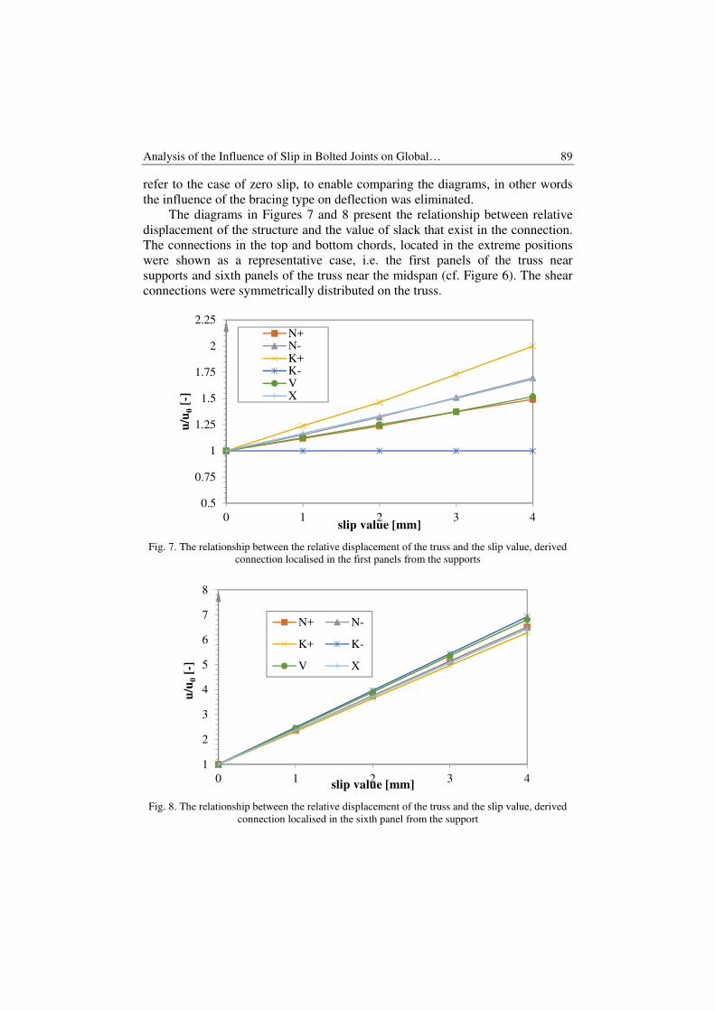
refer to the case of zero slip, to enable comparing the diagrams, in other words
the influence of the bracing type on deflection was eliminated.
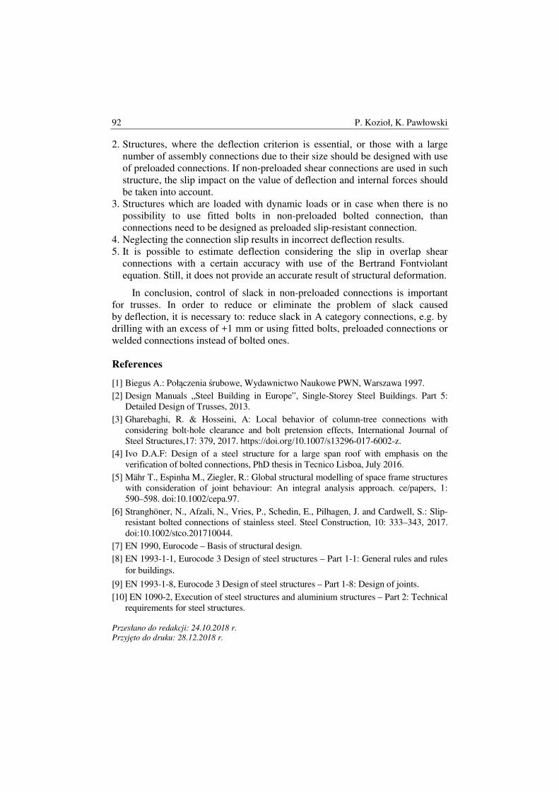
The diagrams in Figures 7 and 8 present the relationship between relative
displacement of the structure and the value of slack that exist in the connection.
The connections in the top and bottom chords, located in the extreme positions
were shown as a representative case, i.e. the first panels of the truss near
supports and sixth panels of the truss near the midspan (cf. Figure 6). The shear
connections were symmetrically distributed on the truss.
Fig. 7. The relationship between the relative displacement of the truss and the slip value, derived
connection localised in the first panels from the supports
Fig. 8. The relationship between the relative displacement of the truss and the slip value, derived
connection localised in the sixth panel from the support
0.5
0.75
1
1.25
1.5
1.75
2
2.25
0 1 2 3 4
u/u
0[-
]
slip value [mm]
N+N-K+K-VX
1
2
3
4
5
6
7
8
0 1 2 3 4
u/u
0[-
]
slip value [mm]
N+ N-
K+ K-
V X

90 P. Kozioł, K. Pawłowski
Increasing the value of potential slip in connections in the truss structure
causes a significant increase in displacements.
Only for truss K- (Fig. 6) and the connection located in the extreme panel
a constant deflection value was obtained, i.e. i.e. the slips in chord connections
do not affect the displacement value, which results from the location of
connections on the so-called zero force members.
The numerical analyses for trusses, where the connections were modelled
directly at the support resulted in a twofold increase of displacement as a result
of maximum slack equal to 4mm. When the connections were modelled in
panels close to the mid-span of the truss, the deflection increased near seven-fold
in comparison to the model without slack in connections. Additionally, the
analysis of diagrams N+ and N- (Fig. 7), where in the first panel the top and
bottom members are zero force members, reveals that the influence of slip in the
bottom chord on the value of these deformations is higher than the slip in the
upper chord.
The analyses are summarized in the graph of the impact of the connection
location on the length of the structure on the relative deflection of the truss
(Fig. 9). The connections in the model were always in pairs (on the top and
bottom chord) and they were placed symmetrically in relation to the centre of the
truss. Six situations were analysed, starting from the position of connection in
the panel No. 1 to its position in the panel No. 6, i.e. located 2.4 m from the
centre of the truss. The slip of 2 mm in the connection was assumed as the
meaningful slip level.
Fig. 9. The relationship between the relative displacement of truss structures and the position of
overlap shear connections (panels No. 1 to 6)
0.5
1
1.5
2
2.5
3
3.5
4
4.5
1 2 3 4 5 6
u/u
0[-
]
connection localisation - panel's number
N+ N-
K+ K-
V X
Bracing type:

Analysis of the Influence of Slip in Bolted Joints on Global… 91
When designing two bolted splice connections on the length of the truss and
placing them in the fifth panel of the truss, one should expect about four-fold
increase in the actual deflection, regardless of the type of truss.
In reference to the geometry of the truss of the damaged conveyor discussed
in Section 2 and, at the same time, an arrangement that is one of the most prone
to slip in connections (according to the conducted analyses, Fig. 9), detailed
results were provided for V type truss for different slip values (Fig. 10).
Fig. 10. The relationship between the relative displacement of truss structures and the position of
overlap shear connections on the top and bottom chords of trusses
The diagram shows the results for truss pattern V, for which the highest
increase in deflection was noted. In this case, the ratio of deflection increase
with the assembly connection approaching the mid-span of the truss is 6.8, and
the maximum deformation at 4 mm slack is 38.1 mm, while for analytical
analysis (according to the Bertrand Fontviolant formula) it is 29.28 mm, which
means a difference of approx. 30%.
In the analysed conveyor, the actual deflections were about 8 times greater
than those calculated in the design process. This results from the fact of the
influence of accumulated slips from several connections on the total deflection
of the structure.
5. Conclusions
In accordance with conducted analyses the following conclusions were drawn:
1. The value of the obtained vertical deflections considering the potential slip in
non-preloaded shear connections corresponds to the measured deflections wrz.
They were obtained for a model with fixed slip of a constant value not
exceeding 4 mm. However, uneven slips on specific connections were not
taken into account, as they are of a random nature.
0.5
1.5
2.5
3.5
4.5
5.5
6.5
7.5
1 2 3 4 5 6
u/u
0[-
]
connection localisation - panel's number
0mm 1mm
2mm 3mm
4mm
Slip value:
92 P. Kozioł, K. Pawłowski
2. Structures, where the deflection criterion is essential, or those with a large
number of assembly connections due to their size should be designed with use
of preloaded connections. If non-preloaded shear connections are used in such
structure, the slip impact on the value of deflection and internal forces should
be taken into account.
3. Structures which are loaded with dynamic loads or in case when there is no
possibility to use fitted bolts in non-preloaded bolted connection, than
connections need to be designed as preloaded slip-resistant connection.
4. Neglecting the connection slip results in incorrect deflection results.
5. It is possible to estimate deflection considering the slip in overlap shear
connections with a certain accuracy with use of the Bertrand Fontviolant
equation. Still, it does not provide an accurate result of structural deformation.
In conclusion, control of slack in non-preloaded connections is important
for trusses. In order to reduce or eliminate the problem of slack caused
by deflection, it is necessary to: reduce slack in A category connections, e.g. by
drilling with an excess of +1 mm or using fitted bolts, preloaded connections or
welded connections instead of bolted ones.
References
[1] Biegus A.: Połączenia śrubowe, Wydawnictwo Naukowe PWN, Warszawa 1997.
[2] Design Manuals „Steel Building in Europe”, Single-Storey Steel Buildings. Part 5:
Detailed Design of Trusses, 2013.
[3] Gharebaghi, R. & Hosseini, A: Local behavior of column-tree connections with
considering bolt-hole clearance and bolt pretension effects, International Journal of
Steel Structures,17: 379, 2017. https://doi.org/10.1007/s13296-017-6002-z.
[4] Ivo D.A.F: Design of a steel structure for a large span roof with emphasis on the
verification of bolted connections, PhD thesis in Tecnico Lisboa, July 2016.
[5] Mähr T., Espinha M., Ziegler, R.: Global structural modelling of space frame structures
with consideration of joint behaviour: An integral analysis approach. ce/papers, 1:
590–598. doi:10.1002/cepa.97.
[6] Stranghöner, N., Afzali, N., Vries, P., Schedin, E., Pilhagen, J. and Cardwell, S.: Slip‐
resistant bolted connections of stainless steel. Steel Construction, 10: 333–343, 2017.
doi:10.1002/stco.201710044.
[7] EN 1990, Eurocode – Basis of structural design.
[8] EN 1993-1-1, Eurocode 3 Design of steel structures – Part 1-1: General rules and rules
for buildings.
[9] EN 1993-1-8, Eurocode 3 Design of steel structures – Part 1-8: Design of joints.
[10] EN 1090-2, Execution of steel structures and aluminium structures – Part 2: Technical
requirements for steel structures.
Przesłano do redakcji: 24.10.2018 r.
Przyjęto do druku: 28.12.2018 r.