analysis of near-wake deflection characteristics of
TRANSCRIPT

echT PressScience
DOI: 10.32604/EE.2021.016357
ARTICLE
Analysis of Near-Wake Deflection Characteristics of Horizontal Axis WindTurbine Tower under Yaw State
Zhen Liu1,3, Jianwen Wang1,2,*, Fuzhong Bai3, Caifeng Wen1,2 and Yunchao Du1
1School of Energy and Power Engineering, Inner Mongolia University of Technology, Hohhot, 010051, China2Key Laboratory of Wind Energy and Solar Energy Utilization Technology, Ministry of Education, Inner MongoliaUniversity of Technology, Hohhot, 010051, China
3School of Mechanical Engineering, Inner Mongolia University of Technology, Hohhot, 010051, China∗Corresponding Author: Jianwen Wang. Email: [email protected]: 01 March 2021 Accepted: 15 July 2021
ABSTRACT
The yaw of the horizontal axis wind turbine results in the deflection of the wake flow field of the tower. Thereasonable layout of wind farm can reduce the power loss of the downstream wind turbine generators dueto the blocking effect of the upstream wake flow and increase the output power of the whole wind farm.However, there is still much space for further research. In this paper, experimental research is conductedon the near-wake deflection characteristics of wind turbine tower under yaw state, expecting the effect ofthrowing away a brick in order to get a gem. In the low-turbulence wind tunnel test, regarding the mostunfavorable position where the rotating blades coincide with the tower, Particle image velocimetry (PIV)technology is used to test the instantaneous velocity field and output power and analyze experimental dataat four different yaw angles, different inflow velocities and heights. Meanwhile, in order to quantitativelyanalyze the laws on wake deflection, the radon transformation is used to analyze the velocity contour forcalculating the wake direction angle, and the results show high reliability. The comprehensive experimentalresults indicate that the near-wake flow field of the tower obviously deflects towards a side in the horizontalplane. With the increase of the yaw angle, the deflection angle of the wake flow field further increases, andthe recovery of wake velocity accelerates. The closer to the blade root, the more complex the flow is, andthe influence of the blade on the near wake of the tower is gradually weakened. The change laws on thewake direction angle with the yaw angle and the blade spanwise direction are obtained. The experiment inthis paper can provide guidance for layout optimization of wind farm, and the obtained data can provide ascientific basis for the research on performance prediction of horizontal axis wind turbine.
KEYWORDS
Horizontal axis wind turbine; yaw; tower; near-wake
1 Introduction
The distance between the upstream wind turbine and the downstream tower is relatively smallin horizontal axis wind turbines. Thus, the rotary/static interference effects between the bladesand the tower of the upwind horizontal axis wind turbines are considerable [1]. Disturbance ofthe upstream blade wakes on the downstream tower modifies the flow characteristics around the
This work is licensed under a Creative Commons Attribution 4.0 International License,which permits unrestricted use, distribution, and reproduction in any medium, provided theoriginal work is properly cited.

1628 EE, 2021, vol.118, no.6
tower. Hence, the wind speed and the flow field in the local area around the tower are signifi-cantly influenced, thus affecting the operating efficiency of downstream wind turbines. Previousstudies [2–4] demonstrated that the aerodynamic tower performance is most unfavorable when theblades completely shield the tower. This is of particular importance in the shutdown state, whichis characterized by high wind speeds. Thus, the flow around the tower is significantly alerted whenblades are in different positions, which affects the aerodynamic force and wind-induced responseof the tower itself. In addition, in the actual working environment of the wind turbine, the winddirection continuously changes. In comparison, the yaw system wind turbine speed is relativelyslow. Therefore, the rotating shaft of wind turbine vane wheel cannot be timely aligned with thedirection of the incoming wind. As a result, the yaw state of the wind turbine is a very commonoperating mode [5,6], and different yaw states will lead to the fluctuation of output power andchange wake characteristics of the tower [7–9]. Therefore, it is of great engineering significanceto the study on the wake characteristics of the wind turbine tower under yaw condition.
In recent years, many researchers have investigated the interaction between the blades, thewind turbine tower, and its wake characteristics. Ren et al. investigated the interference effecton the wind turbine blades and tower wakes based on CFD method [10]. Wen et al. analyzedpower fluctuation and losses due to wind shear and tower shadow for NREL 5 MW baselinewind turbine with blade element momentum (BEM) theory [11] and carried out a large numberof experimental studies on the load characteristics of wind turbine tower under yaw [12]. Caoet al. [1] employed two-dimensional Navier-Stokes (N-S) equations to study the interference effectof the upstream blade wakes on the downstream tower, finding that when the tower was nearthe blade wake, there was a strong mutual-interference, and this interference altered the flowsymmetry around the tower cylinder. Zhang et al. revealed the influence law of wind azimuthson generated power of wind turbines placed in serial configuration. Numerical simulation wascombined with theoretical analysis to investigate the change rule of horizontal axis wind turbinewake under yaw operating conditions [13,14]. Wake shift effect and its influence on downstreamwind turbines were investigated. Liao et al. simulated two full-scale 5 MW wind turbines withserial arrangement by unsteady CFD method [15,16] and studied the flow mechanism of wakeoffset control and its influence on the downstream wind turbine. Ke et al. studied a five MW windturbine tower-blade system in [17] Large eddy simulation method (LES). Furthermore, contrastiveanalysis was conducted on the influence of different yaw angles on mean surface wind pressure,fluctuating wind pressure, lift coefficient, drag coefficient, and flow characteristics around thetower and the wake.
Existing studies have mainly focused on the flow around the blades, the unsteady interferencebetween the tower and the blades, and numerical simulation of flow field characteristics of windturbine wake under yaw state. However, few systematic discussions regarding yaw angle influenceon the flow field around the tower of the wind turbine exist. Furthermore, there are even fewerexperimental studies. In this paper, a small horizontal axis wind turbine is studied via PIVtechnique in a low turbulence wind tunnel. Experimental study on the tower near-wake flow fieldis conducted for the most unfavorable position of a test blade at four different yaw angles andvarious test heights. By analyzing the experimental data, the yaw angle influence rule of the towernear-wake flow field is discussed. Furthermore, skew angles of tower wakes under different yawangles are obtained by applying digital image processing technology to the analysis of the velocitycontours.

EE, 2021, vol.118, no.6 1629
2 Experimental Setup
Experiments were conducted in the open section of B1/K2 direct-action low-speed windtunnel. The wind tunnel is composed of power section, rectification section, contraction section,closed test section, diffusion section, and open test section. The total length of the wind tunnelis 24.59 m, and the diameter of the open test section is 2.04 m. Maximum stable wind speed is20 m/s, digital down converter technology is used for wind speed adjustment. The wind turbineis novel S airfoil profile 3-blade horizontal axis wind turbine. The main parameters are listed inTab. 1.
Table 1: Major parameters of wind turbine
Major parameter Value Blade Wind turbine
Tower height (m) 1.7Tower diameter (mm) 100Blade length (mm) 700Rotor diameter (mm) 1440Rated wind speed (m/s) 8Blade starting speed (m/s) 3.1Rated power (W) 300
The flow field measurement is performed through the PIV system produced by LaVision fromGermany, which includes:
1) YLF LDY 300 high repetition rate laser, with the maximum output power of 150 W andpulse width of 100 ns. Energy of a single laser beam at the trigger frequency of 15 Hz is30 mJ, and the output wave-length is 527 nm.
2) Imaging system: High Speed Star 8 high sensitivity and megapixel resolution CCD camera,with the sampling frequency of 15 Hz.
3) VZ11-1032 synchronous controller, which simultaneously controls timing signals of thehigh-speed camera, the laser, and the image acquisition and processing software to ensurethe synchronized triggering of all systems. The rotational speed of the rotor is adjustedvia resistive load, while NORMA5000 power analyzer from Fluke is used to monitor theoperating parameters, such as the output power and the rotational speed.
Adjustment of the wind turbine blades yaw angle is implemented by controlling a dynamicyaw rotary platform of the small wind turbine. The rotary platform was independently developedby the research group, and its outline structure is shown in Fig. 1. On this platform, TP3340motion controller is used to control the position, while precise control of the yaw angle isachieved via high inertia MDMF302L1H6 M servo motor, acting as the motion actuator.

1630 EE, 2021, vol.118, no.6
Figure 1: Dynamic yaw bench of miniature wind turbine: 1. Model of small wind turbine, 2.Rotating platform, 3. Base, 4. Servo motor
3 Experimental Methods
The yaw angle γ of the wind turbine is defined as the angle between the incoming flow andthe rotating shaft of the wind turbine, as demonstrated in Fig. 2a. The wind tunnel offers stableincoming flow with fixed flow direction and adjustable velocity. Therefore, during experimentalinvestigations, the yaw working conditions of the small wind turbine are implemented by fixingthe wind direction of the incoming flow and rotating the wind turbine as demonstrated in Fig. 2b.
Figure 2: Diagram of the yaw angle from above: (a) Yaw angle of wind turbine, (b) Experimentalsimulation of yaw angle

EE, 2021, vol.118, no.6 1631
During experimental investigation, the wind turbine was placed in a jet stable region ofthe wind tunnel opening section, and the influence of blockage ratio could not be considered.The turbulence intensity under the experimental wind speed was less than 1.4%. The bladeson the rotor rotate in the counterclockwise direction. The flow field measurement experimentis carried out when the test blade is at the most unfavorable position, i.e., when the blade isoverlapped with the tower. Driven by the dynamic yaw rotating platform, the small wind turbinerotates counterclockwise to adjust the yaw angle. PIV technique is used to study the effect ofdifferent yaw angles on the near-wake flow field of wind turbine tower under multiple workingconditions.
The following working condition parameters are employed in the experiments. Yaw angle γ is0◦, 10◦, 20◦, or 30◦. Incoming flow velocity V is 6, 7, 8, or 9 m/s, while the blade tip speed ratioλ is equal to 4.5, 5, 5.5, or 6. The measurement area is located in the near-wake flow field directlybehind the tower. It is tangent to the tower and is spanned toward four spanwise height planesof 0.3, 0.4, 0.5 and 0.6R (defined as 1, 2, 3 and 4# planes) along the test blade. The shootingarea has the size of 200 mm× 200 mm. The PIV measurement area and coordinate systemare shown in Fig. 3. The direction of the tower is defined as z-axis, with the upward directiondefined as positive; the x-y plane is the plane where the base is located, which is perpendicularto the tower. The horizontal inflow direction is defined as the positive direction of the x-axis,and the positive direction of the y-axis is consistent with the rotation direction of the windwheel. The central axis of the tower is located at y = 100 mm, and the size of the imaging areais 200 mm× 200 mm. The measured area and PIV coordinates are shown in Fig. 3. The z-axisrepresents the centerline of the tower, with the upward direction defined as positive. Plane x-yis parallel to the tower base, while its normal vector is aligned with the tower. The direction ofhorizontal incoming flow is defined as the positive direction of x-axis. The positive direction ofy-axis is consistent with the rotational direction of the rotor.
Figure 3: Schematic representation of PIV measurement region
In order to measure the tower flow field during the most unfavorable blade position, it isnecessary to accurately determine whether the blades interact with the right front of the towerand transmit the Boolean signal to the tachometer and the PIV system to achieve synchronousacquisition or control. More specifically, the following method is applied. Synchronous trigger
1632 EE, 2021, vol.118, no.6
device and rotational speed measuring device are designed for the acquisition of rotor speed andpulse signal of phase-locked positioning. Then, diffusion photoelectric sensor is mounted on theturbine side generator behind the rotor, thus adhering reflecting material to the predeterminedcircumferential trigger positions on the suction side of the wind turbine rotary blades. Whenthe test blade rotates to the location directly in front of the tower, i.e., the location where theblade is heading straightly downwards, it is set as the triggering position. The photoelectric sensorreceives an abrupt optical signal, which is then converted into pulse signal and transmitted to thetachometer to measure the rotational speed of the wind turbine. This signal is also utilized as theexternal trigger signal for the PIV measurement system synchronizer to control the initiation ofcamera photographing, thus ensuring the PIV measurement system start of data acquisition. Inthe experiments, the cabin surfaces are painted with black flat paint to reduce the effect of lightreflection on the measurement results.
4 Experimental Results and Analysis
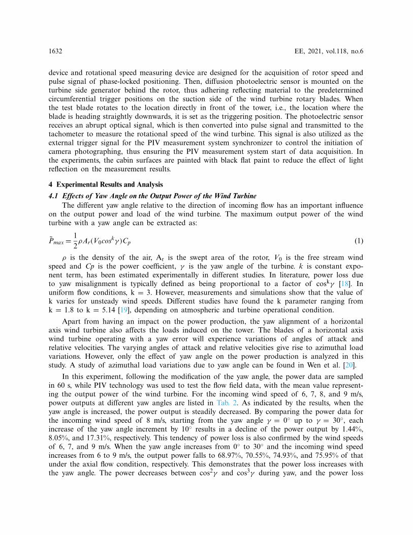
4.1 Effects of Yaw Angle on the Output Power of the Wind TurbineThe different yaw angle relative to the direction of incoming flow has an important influence
on the output power and load of the wind turbine. The maximum output power of the windturbine with a yaw angle can be extracted as:
P̃max= 12ρAr(V0coskγ )Cp (1)
ρ is the density of the air, Ar is the swept area of the rotor, V0 is the free stream windspeed and Cp is the power coefficient, γ is the yaw angle of the turbine. k is constant expo-nent term, has been estimated experimentally in different studies. In literature, power loss dueto yaw misalignment is typically defined as being proportional to a factor of coskγ [18]. Inuniform flow conditions, k = 3. However, measurements and simulations show that the value ofk varies for unsteady wind speeds. Different studies have found the k parameter ranging fromk = 1.8 to k = 5.14 [19], depending on atmospheric and turbine operational condition.
Apart from having an impact on the power production, the yaw alignment of a horizontalaxis wind turbine also affects the loads induced on the tower. The blades of a horizontal axiswind turbine operating with a yaw error will experience variations of angles of attack andrelative velocities. The varying angles of attack and relative velocities give rise to azimuthal loadvariations. However, only the effect of yaw angle on the power production is analyzed in thisstudy. A study of azimuthal load variations due to yaw angle can be found in Wen et al. [20].
In this experiment, following the modification of the yaw angle, the power data are sampledin 60 s, while PIV technology was used to test the flow field data, with the mean value represent-ing the output power of the wind turbine. For the incoming wind speed of 6, 7, 8, and 9 m/s,power outputs at different yaw angles are listed in Tab. 2. As indicated by the results, when theyaw angle is increased, the power output is steadily decreased. By comparing the power data forthe incoming wind speed of 8 m/s, starting from the yaw angle γ = 0◦ up to γ = 30◦, eachincrease of the yaw angle increment by 10◦ results in a decline of the power output by 1.44%,8.05%, and 17.31%, respectively. This tendency of power loss is also confirmed by the wind speedsof 6, 7, and 9 m/s. When the yaw angle increases from 0◦ to 30◦ and the incoming wind speedincreases from 6 to 9 m/s, the output power falls to 68.97%, 70.55%, 74.93%, and 75.95% of thatunder the axial flow condition, respectively. This demonstrates that the power loss increases withthe yaw angle. The power decreases between cos2γ and cos3γ during yaw, and the power loss

EE, 2021, vol.118, no.6 1633
law is similar to cos3γ when the incoming wind speed is greater than or equal to the rated windspeed. This result also validated the credibility of the experiment.
Table 2: Output power at different yaw angles (W)
Wind speed
Yaw angle 6 m/s 7 m/s 8 m/s 9 m/s
0◦ 103.04 160.86 230.62 330.9710◦ 100.61 157.45 227.3 327.9920◦ 86.64 141.31 209 298.0330◦ 71.07 113.45 172.82 251.37Percentage of output power drop at maximumyaw angle (30◦) (%)
68.97 70.55 74.93 75.95
4.2 Experimental Velocity Field Measurement on Planes with Different Blade HeightsWhen the velocity of the incoming flow is v = 7 m/s, the blade tip speed ratio is λ= 5 and
the yaw angle is γ = 10◦, the velocity fields on four planes numbered 1# to 4# are measured.The resultant axial velocity contours of the tower wake flow are depicted in Fig. 4. In order tohighlight the proportional relationship between the tower and the measuring area, horizontal andvertical axes are standardized by dividing them by the radius of the tower, which are expressedas Cx and Cy. Owing to the blades obstruction on the tower and the rotation effect of the rotor,the wake flow of the tower demonstrates conspicuous change. After the incoming flow passesthrough the tower, the area with low-speed stationary the stream with some velocity deficit isformed close to the back of the tower. When a blade rotates around the location in front of thetower, change of stagnation point location is induced at the leading edge. Therefore, the towerwake deflects and the flow on one side of the tower is accelerated. This leads to asymmetry ofthe cylinder bypass flow in the near-wake flow field of the tower. Since the experimental rotorrotates counterclockwise, the tower wake deflects towards the right side, i.e., towards the positivedirection of the y-axis in the velocity contours.
From blade height planes 1# to 4#, near-wake deflection degree of the tower shows a gradualdecrease trend, and the flow is eventually stabilized. This is due to a decrease in the chord lengthof the blade profile, while simultaneously increasing the torsional angle of the blade when movingfrom the blade root to its tip. Blade obstructing effect on the incoming flow decreases, whileeffects of the incoming flow bypassing the blades on the near-wake flow field of the tower decline.Thus, the deflection degree of the wake is reduced. The closer it is to the blade root, the moresignificant the influence of the blade on the near-wake flow field of the tower. With the increase ofthe blade height, this effect gradually decreases. Meanwhile, due to a disturbance of the upstreamblades, the incoming flow, passing through the blades, attaches to the tower. Then, it bypasses thetower and flows to the leeside of the tower, thus forming complicated flow eddies of a certainscale that are located near the blade root. On plane 1#, small-scale eddies are captured.

1634 EE, 2021, vol.118, no.6
Figure 4: Axial velocity contour of the tower near-wake flow at different spanwise heights forγ = 10◦ and v = 7 m/s (a) 1# (b) 2# (c) 3# (d) 4#
4.3 Experimental Measurement of Wake Flow Fields at Different Yaw Angles4.3.1 Effects of Yaw Angle on Tower Wake Flow Fields
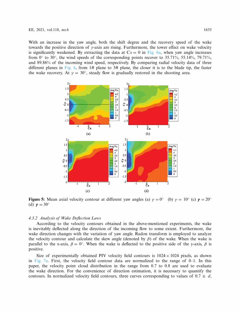
When the incoming flow is v = 7 m/s, the blade tip speed ratio is equal to λ = 5, and theyaw angle is equal to γ = 0◦, 10◦, 20◦ and 30◦. For these parameters, the mean resultant velocitycontour on plane 3# is presented in Fig. 5. By comparing the results, the near-wake flow fieldbehind the tower shows certain velocity deficit. Furthermore, when the yaw angle is 0◦ and theblade is in the most unfavorable position, the mutual interference between the tower and theblades is most remarkable and the velocity deficit of the wake is most critical. When the yawangle is relatively small, the obstructing effect of the blades is distinct. With an increase in theyaw angle, blade effect on the tower wake is decreased, and the recovery of wake velocity issignificantly accelerated.
Mean axial velocity contour of the wake flow field in the front section of the tower, shownin Fig. 5, is quantitatively analyzed. Straight line Cy = 0 is taken as the monitoring location(i.e., radial location of the tower). Data points are extracted at a constant interval to depict thevariation curve for mean resultant velocities at four different yaw angles, as shown in Fig. 6.
EE, 2021, vol.118, no.6 1635
With an increase in the yaw angle, both the shift degree and the recovery speed of the waketowards the positive direction of y-axis are rising. Furthermore, the tower effect on wake velocityis significantly weakened. By extracting the data at Cx= 0 in Fig. 6a, when yaw angle increasesfrom 0◦ to 30◦, the wind speeds of the corresponding points recover to 35.71%, 55.14%, 79.71%,and 89.86% of the incoming wind speed, respectively. By comparing radial velocity data of threedifferent planes in Fig. 6, from 1# plane to 3# plane, the closer it is to the blade tip, the fasterthe wake recovery. At γ = 30◦, steady flow is gradually restored in the shooting area.
Figure 5: Mean axial velocity contour at different yaw angles (a) γ = 0◦ (b) γ = 10◦ (c) γ = 20◦(d) γ = 30◦
4.3.2 Analysis of Wake Deflection LawsAccording to the velocity contours obtained in the above-mentioned experiments, the wake
is inevitably deflected along the direction of the incoming flow to some extent. Furthermore, thewake direction changes with the variation of yaw angle. Radon transform is employed to analyzethe velocity contour and calculate the skew angle (denoted by β) of the wake. When the wake isparallel to the x-axis, β = 0◦. When the wake is deflected to the positive side of the y-axis, β ispositive.
Size of experimentally obtained PIV velocity field contours is 1024× 1024 pixels, as shownin Fig. 7a. First, the velocity field contour data are normalized to the range of 0–1. In thispaper, the velocity point cloud distribution in the range from 0.7 to 0.8 are used to evaluatethe wake direction. For the convenience of direction estimation, it is necessary to quantify thecontours. In normalized velocity field contours, three curves corresponding to values of 0.7 ± d,

1636 EE, 2021, vol.118, no.6
0.75 ± d, and 0.8 ± d are extracted (Fig. 7b). By controlling the value of d, which is chosenas d = 0.002 in this paper, the width of the curve can be adjusted. Almost none of the velocityfield contours show a strict linear distribution of wakes. Hence, the traditional linear directionestimation algorithm cannot be used to calculate the wake direction. In this paper, Fig. 7b isregarded as a digital image, and Radon transformation [21] is introduced to estimate the anglebetween the longest approximate straight-line segment and the x-axis, which is regarded as thecalculation result of the wake skew angle.
Figure 6: Mean axial velocity at the radial position of the tower (Cy = 0) (a) 1# (b) 2# (c) 3#
Radon transform of image f (x, y) along the random direction represents the gray projectionof the image of the specific direction. Its mathematical expression can be written as:
Rβ(x′, y′)=∫ ∞
−∞f (x′ cosβ − y′ sinβ, x′ sinβ + y′ cosβ)dy′ (2)

EE, 2021, vol.118, no.6 1637
where β denotes the included angle between the projection direction and x-axis, with the corre-sponding range of β ∈ [0◦, 179◦]. Before applying Eq. (2), image coordinate transformation shouldbe implemented according to the following equation:[x′
y′
]=
[cosβ sinβ
− sinβ cosβ
] [x
y
](3)
Radon transform results of Fig. 7b are shown in Fig. 7c, where the three brightest spotscorrespond to approximately linear segments of three curves in Fig. 7b. By extracting the abscissaof each of the three brightest spots and subtracting 90◦, the average wake deflection angle β
relative to the direction of the incoming wind speed in the measured area can be obtained.
Figure 7: Result of main direction discrimination, γ= 20: (a) Velocity contour, (b) Main directionextraction of wake, (c) Radon transform (Wake direction determination)
Wake skew angles at incoming wind speed of v= 7 m/s on four planes 1# to 4# of differentblade heights and at four different yaw angles are calculated. The results are presented in Fig. 8.According to the calculation results, if plane 3# (blade height of 0.5R) is omitted during theprocess of yaw angle γ increasing from 0◦ to 30◦, the deflection angle of the wake gradually

1638 EE, 2021, vol.118, no.6
increases and it is always greater than the yaw angle. Degree of the wake deflection varies onplanes with different blade heights, e.g., wake skew angles are 41◦, 43◦ and 46◦ for γ = 30◦.Nevertheless, wake deflection rule on plane 3# is slightly different from that on the remainingthree planes. This is caused by the local effect on the leeside of the tower induced by vortexsystems of different scales in wakes of upstream blades. The results can play a guiding role inoptimizing the layout of downstream wind turbine generators and improving the overall outputpower of wind farms. In the experiment, due to the limitations of PIV shooting area, no completeand reliable changes of vortex system structure are captured. In future works, researchers canconsider expanding the shooting area, and collecting the full field information on the near wakeof the tower to further explore the change laws of complex wake flow at the leeward side of thetower.
Figure 8: Calculation results of wake skew angles at different yaw angles
5 Conclusions
Particle image velocimetry (PIV) experiments are carried out on the near-wake flow field ofthe small horizontal axis wind turbine tower at four yaw angles and four different test heights. theoutput power , structural change of the wake flow field , and the change rule of wake skew angleat different yaw angles are compared and analyzed. The following conclusions are drawn:
(1) Experimental investigation of yaw angle effects on the power output of wind turbine isconducted. Compared with the axial flow condition, the power of the experimental windturbine decreases between cos2 γ and cos3 γ during yaw, and the power loss law is similarto cos3 γ when the incoming wind speed is greater than or equal to the rated wind speed.
(2) According to the results for the yaw angle of γ = 10◦, when the blade is at the locationwith the greatest influence on the wake flow of the tower, under the rotation effect ofrotor and the interference caused by the upstream blades, the stagnation point positionof the tower upwind side leading edge changes. Near-wake flow field is deflected to theside and subjected to asymmetric distribution relative to the centerline plane of the tower.

EE, 2021, vol.118, no.6 1639
Furthermore, the closer to the height plane of the blade root, the more complex the wakeflow of the tower is. Moreover, more significant the influence of the blade on the nearwake of the tower.
(3) With an increase in the yaw angle, the deflection degree of near-wake towards the positivedirection of y-axis and the recovery speed are both accelerated. Furthermore, the towerinfluence on the wake flow velocity is significantly weakened. To quantitatively analyze thedeflection law of the wake, Radon transformation is employed to calculate the wake skewangle. The calculation results are scientific and reliable, the method has good robustness,it is relatively easy to implement and has a high degree of automation.
Revelation of the change laws on the near-wake direction angle of the tower under yaw statecan provide theoretical guidance for optimizing the layout of downstream wind turbine generators.However, due to the limitation of PIV shooting area and sampling frequency in this experiment,complete and reliable structural changes of wake vortex system were not captured. In futureresearch, the splicing technology can be used to expand the shooting area, collect the full fieldinformation on the near wake of the tower, and further explore the complex change laws of wakeflow on the leeward side of the tower.
Funding Statement: This work was Supported by the National Natural Science Foundation ofChina (No. 51766014) and the Natural Science Foundation of Inner Mongolia AutonomousRegion (Nos. 2019MS05024, 2020LH06002).
Conflicts of Interest: The authors declare that they have no conflicts of interest to report regardingthe present study.
References1. Cao, R. J., Hu, J. (2006). Flow interaction between HAWT rotor wake and downstream circular tower.
Acta Energiae Solaris Sinica, 27(4), 326–330. DOI 10.3321/j.issn:0254-0096.2006.04.002.2. Zhang, L. T., Guo, L. F., Rong, Q. (2020). Single parameter sensitivity analysis of Ply parame-
ters on structural performance of wind turbine blade. Energy Engineering, 117(4), 196–207. DOI10.32604/EE.2020.010617.
3. Wang, Q., Zhou, H., Wan, D. L. (2012). Numerical simulation of wind turbine blade-tower interaction.Journal of Marine Science and Application, 11(3), 321–327. DOI 10.1007/s11804-012-1139-9.
4. Ke, S. T., Yu, W., Wang, T. G., Zhao, L., Ge, Y. J. (2016). Wind loads and load-effects of large-scalewind turbine tower with different halt positions of blade. Wind and Structures, 23(6), 559–575. DOI10.12989/was.2016.23.6.559.
5. Jeong, M. S., Kim, S. W., Lee, I., Yoo, S. J., Park, K. C. (2013). The impact of yaw error onaeroelastic characteristics of a horizontal axis wind turbine blade. Renewable Energy, 60(5), 256–268.DOI 10.1016/j.renene.2013.05.014.
6. Zhang, S. W., Huang, L. X., Song, D. R., Xu, K., Song, X. P. (2021). Model predictive Yaw controlusing fuzzy-deduced weighting factor for large-scale wind turbines. Energy Engineering, 118(2), 237–250. DOI 10.32604/EE.2021.014269.
7. Majid, B., Fernando, P. A. (2016). Experimental and theoretical study of wind turbine wakes in yawedconditions. Journal of Fluid Mechanics, 806, 506–541. DOI 10.1017/jfm.2016.595.
8. Mühle, F., Schottler, J., Bartl, J., Futrzynski, R., Evans, S. et al. (2018). Blind test comparison on thewake behind a yawed wind turbine. Wind Energy Science, 3(2), 883–903. DOI 10.5194/wes-3-883-2018.
9. Schottler, J., Bartl, J., Mühle, F., Stran, L., Hlling, M. (2018). Wind tunnel experiments on windturbine wakes in yaw: Redefining the wake width. Wind Energy Science Discussions, 3(1), 257–273.DOI 10.5194/wes-2017-58.

1640 EE, 2021, vol.118, no.6
10. Ren, N., Ou, J. (2009). Aerodynamic interference effect between large wind turbine blade and tower.Computational structural engineering. Springer Netherlands.
11. Wen, B. R., Wei, S., Wei, K. X., Yang, W. X., Peng, Z. K. et al. (2018). Influences of wind shearand tower shadow on the power output of wind turbine. Journal of Mechanical Engineering, 54(10),124–132. DOI 10.3901/JME.2018.10.124.
12. Wen, B. R., Tian, X. L., Dong, X. J., Peng, Z. K., Zhang, W. M. et al. (2019). A numerical study onthe angle of attack to the blade of a horizontal-axis offshore floating wind turbine under static anddynamic yawed conditions. Energy, 168, 1138–1156. DOI 10.1016/j.energy.2018.11.082.
13. Li, D. Y., Zhang, L. R., Wang, J. W., Yu, T. T., Lu, C. (2018). Effect on the wake of hori-zontal axis wind turbine under yaw condition. Renewable Energy Resources, 36(1), 105–110. DOI10.13941/j.cnki.21-1469/tk.2018.01.016.
14. Guo, M. F., Zhang, L. R., Li, D. Y., Wang, X. L., Niu, J. J. (2020). Analysis on wake deviation andturbulence characteristics of horizontal-axis wind turbine under yawed condition. Journal of Drainageand Irrigation Machinery Engineering, 38(7), 702–707. DOI 10.3969/j.issn.1674-8530.18.0273.
15. Liao, W. P., Li, C., Yang, J. (2017). Investigation on flow mechanism of a wind farm based on yawedwind turbine using wake deflection control strategy. Journal of Chinese Society of Power Engineering,37(8), 655–662. DOI 10.3969/j.issn.1674-7607.2017.08.010.
16. Liao, W. P., Li, C., Yang, J. (2018). Characteristics of a yawed wake and its influence on downstreamwind turbine. Acta Energiae Solaris Sinica, 39(9), 2462–2469. DOI CNKI:SUN:TYLX.0.2018-09-012.
17. Wang, X. H., Ke, S. T. (2017). Study on aerodynamic performances of large wind turbine towersconsidering yaw and blade interferences. Proceedings of the Chinese Society for Electrical Engineering,38(15), 4546–4554+4655. DOI 10.13334/j.0258-8013.pcsee.171561.
18. Kragh, K. A., Hansen, M. H. (2015). Potential of power gain with improved yaw alignment. WindEnergy, 18(6), 979–989. DOI 10.1002/we.1739.
19. Madsen, H. A., Srensen, N. N., Schreck, S. (2003). Yaw aerodynamics analyzed with three codes incomparison with experiment. 41st Aerospace Sciences Meeting and Exhibit, Reno, Nevada.
20. Wen, B. R., Li, Z. L., Jiang, Z. H., Peng, Z. K., Dong, X. J. et al. (2020). Experimental study on thetower loading characteristics of a floating wind turbine based on wave basin model tests. Journal ofWind Engineering and Industrial Aerodynamics, 207. DOI 10.1016/j.jweia.2020.104390.
21. Bai, F. Z., Zhang, T. Y., Gao, X. J., Xu, Y. X. (2018). Local bending measurement of laserstripe images based on Fourier-polar transformation. Acta Optica Sinica, 38(8), 197–203. DOI10.3788/AOS201838.0815019.