analysis of forced convection heat transfer to improve the
TRANSCRIPT

International Research Journal of Engineering and Technology (IRJET) e-ISSN: 2395-0056
Volume: 08 Issue: 01 | Jan 2021 www.irjet.net p-ISSN: 2395-0072
© 2021, IRJET | Impact Factor value: 7.529 | ISO 9001:2008 Certified Journal | Page 205
Analysis of Forced Convection Heat Transfer to Improve the Thermal
Performance by using Pipe with Triangular Fin Inserts
Sahil Sunil Patil1, Shivayogi Ashok Shetty2, Amol Dhumal3
1Sahil Sunil Patil, Bachelor of Mechanical Engineering 2Shivayogi Ashok Shetty, Bachelor of Mechanical Engineering
3Amol Dhumal, Professor, Dept. of Mechanical Engineering, DR. D.Y. Patil College of Engineering, Management & Research, Akurdi, Maharashtra, India.
---------------------------------------------------------------------***----------------------------------------------------------------------Abstract - The Heat transfer enhancement processes in industrial, Automotive and domestic application involves the conversion, transfer and utilization of energy. The Enhancement of heat transfer in such several applications can significantly improve the thermal performance of heat-based equipment’s are called as heat augmentation techniques. Heat augmentation techniques used to increase the convective heat transfer coefficient by increasing the turbulence of the fluid. This technique also leads to an increase in pressure drop and hence the pumping cost.
Hence the augmentation technique should be made optimal between the heat transfer rate and pressure drop.
Key Words: Heat Transfer, triangular fin insert, Renault number, Nusselt number, Friction factor, Heat transfer coefficient, pressure drop.
1. INTRODUCTION
Forced convection heat transfer is a mechanism or type of transport in which fluid motion is generated by an external source (like a pump, fan, suction device, etc.). It should be considered as one of the main methods of useful heat transfer as significant amounts of heat energy can be transferred very efficiently. This mechanism is found very commonly in everyday life, including air conditioning, central heating, steam turbines and many other machines. It is used in many industries such as in prilling tower of fertilizer industry, in electronics industry especially in computers where processor are cooled by blowing air by the fan, in food industry for Baking of bread Ice cream hardening rooms Meat chillers, for soil and asphalt testing, In forced convection ovens ideal for baking, drying, conditioning, sterilizing and quality control etc. , for cooling inside the electronic components such as laptops, computers, laptop gaming devices, in power plants such as geothermal powerplant, nuclear power plant, etc. For experimental work, pipe with triangular fins inserts. These inserts have pitch(p=20mm) and spacing(s=100mm).
1.1 HEAT TRANSFER ENHANCEMENT
Heat transfer enhancement is the procedure of redesigning a heat transfer surface or the flow cross section to either increase the heat transfer coefficient between the surface and a fluid or the surface area so as to effectively
sustain higher heat loads with a smaller temperature difference. Heat transfer enhancement may also be accomplished by surface or fluid vibration, electrostatic fields or mechanical stirrers. These latter methods are often referred to as active techniques because they required the application of external power.
Although, active techniques are recognized in the research literature their practical applications have been very limited. Therefore, in this section, we focus on some specific example of passive techniques. i.e. those based on modification of the heat transfer surface a more complete and extended discussion of the full spectrum of enhancement techniques can be found in reference mangle. Increases in heat transfer due to surface treatment can be accomplished by increased surface area, increased turbulence, and improved mixing or flow swirl. These effects generally cause in an increase in pressure drop in addition to the increase in heat transfer. However, with appropriate performance evaluation and concomitant optimization, significant heat transfer improvement relative to a smooth (untreated) heat transfer surface of the same nominal (base) heat transfer area can be achieved for a variety of applications. The increasing attractiveness of different heat transfer enhancement techniques are gaining industrial importance because forced convection offers the opportunity:
1. To reduce the surface area of heat transfer required for a given application and therefore reduces the cost.
2. Increase the heat duty of the forced convection equipment and
3. Permit closer approach temperature.
To determine the economic benefits of enhancement in any practical application a complete analysis is required. Such an analysis must include to possible increased first cost because of the enhancement, increased forced convection heat transfer performance, the effect on operating costs. Accelerating fouling can quickly eliminate any increase in the heat transfer coefficient achieved by enhancement of a clean surface. Nevertheless, in the present-day concerns of sustainable energy utilization and the need for conservation the benefits of using enhancement techniques in most system cannot be overstated.
International Research Journal of Engineering and Technology (IRJET) e-ISSN: 2395-0056
Volume: 08 Issue: 01 | Jan 2021 www.irjet.net p-ISSN: 2395-0072
© 2021, IRJET | Impact Factor value: 7.529 | ISO 9001:2008 Certified Journal | Page 206
1.2 ADVANTAGES OF AUGMENTATION TECHNIQUES
The benefits which can be seen by installing tabulators can be seen below again this will depend on the type of forced convection as well as the type of issues which you might be trying to overcome.
Improved Heat Transfer.
Heat Transfer Coefficient improvement by over 3 times.
Improved Performance within apparatus.
Convert Laminar Flow to Turbulent Flow.
Self-Cleaning.
Reduction in Fouling.
Reduction in Film Build up.
Reduction of costs during downtime.
Constant uniform temperature.
Reduces gradients which can cause thermal breakdown.
Easy to install and remove.
2. LITERATURE REVIEW
Arthur E. Bergles et al [1], focuses on the characterization of twisted-tape-induced helical swirl flows for enhancement of forced convective heat transfer in single-phase and two-phase flows. Frequent usage is to retrofit existing heat forced convection to upgrade their heat load capacity. When twisted tapes are incorporated in the design of new forced convection, then, for a specified heat duty and process application, significant size reduction can be achieved relative to that in a plain tubular exchanger. Structure and Scaling of Single-Phase Swirl Flow in that twisted tape induced swirl flow pattern & computational characteristics of swirl in circular tubes with twisted tape inserts with a variation of Reynolds no. are studied. The primary mechanism necessitates conveying a centrifugal force component to the longitudinal fluid motion, which superimposes secondary circulation over the main axial flow to promote cross-stream mixing. Correlations between heat transfer coefficient and friction factor correlations are presented for laminar as well as turbulent and the damping effect of swirl on the transition region is emphasized.
Giovanni Tanda et al. [2], paper focuses on cooling techniques for vanes and blades of advance gas turbine operate at high entry gas temperature. Rib turbulators periodically positioned along the main direction of the flow where one of the first improvements of blade internal cooling. For this experiment, rib turbulators are inclined at 45 deg and
experimental study is carried out on forced convection heat transfer in channels. Heat transfer performance is usually better for the higher rib pitch-to-height ratio despite the fact that the number of ribbed walls one or two.
Jozef Cernecky et al. [3], the paper deals with visualization of temperature fields in the vicinity of profiled heat transfer surfaces and a subsequent analysis of local values of Nusselt numbers by forced air convection in an experimental channel. The effect of heat transfer area roughness on heat transfer enhancement by forced convection experiments were carried out at Re 462 up to 2338 at the distances between heat transfer surfaces of 0.025m and 0.035 m. For visualization of Temperature Fields, Holographic Interferometry was used.
M. Moawed et.al. [4] have investigated the experimental study of forced convection from helical coiled tubes. He uses the different diameter ratios (D/d0) ranged from 7.0862 to 16.142 and pitch ratio (P/d0) ranged from 1.81 to 3.205. The Reynolds number range he used as 6.6 * 102 to 2.3 * 103. The test was carried out on an open circuit airflow wind tunnel. The test section is 300*300 mm in dimension and 420mm long. It is made up of a steel plate fabricated by a sheet of compressed wood and covered by formic. He used a helical coil made from copper in the test section. He mounted a number of thermocouples depending upon the number of coils and found that for the same pitch ratio, the value of Nusselt changes with the value of diameter ratio i.e. Nusselt number is directly proportional to the diameter ratio. He also found that at constant diameter ratio, Nusselt number is inversely proportional to pitch ratio.
Dr. Anirudh Gupta et al. [5], In this journal the Passive heat transfer techniques improved by the different researchers, are discussed, which shows many researchers are taking interest to enhance heat transfer rate with passive methods. Dimple protrude and rough surfaces etc passive methods are used in forced convection, air heaters and heat sinks to enhance heat transfer. Also, heat transfer enhancement techniques are discussed in detail which includes passive, active and compound techniques. Surface or geometrical modifications are generally used by passive techniques, to the flow channel by including inserts or additional devices. A compound augmentation technique is the one where more than one of the above-mentioned techniques is used in combination with the purpose of further improving the thermohydraulic performance of forced convection.
M.M.K. Bhuiya et.al. [6] have investigated the effect of turbulence flow through a tube using double helical tape inserts. He used a helical tape with helix angle 9ᵒ, 15ᵒ, 21ᵒ, 28ᵒ and Reynolds number ranges 22000 to 51000. He used a brass tube with a 70 mm inner diameter and a 90 mm outer diameter with 1500 mm length. the tapes are made up of mild steel, for helix angle 9ᵒ,15ᵒ,21ᵒ, 28ᵒ corresponding pitches 600mm, 770mm,1035mm and 1500mm. he found that the Nusselt number and friction factor was increased by a significant amount.

International Research Journal of Engineering and Technology (IRJET) e-ISSN: 2395-0056
Volume: 08 Issue: 01 | Jan 2021 www.irjet.net p-ISSN: 2395-0072
© 2021, IRJET | Impact Factor value: 7.529 | ISO 9001:2008 Certified Journal | Page 207
Naga Sarada S., et.al. [7] investigated that the augmentation of turbulent flow heat transferrin a horizontal tube by means of mesh inserts with air as the working fluid. He observed that the enhancement of heat transfer by using mesh inserts when compared to a plain tube at the same mass flow rate is more by a factor of 2 times whereas the pressure drop is only about a factor of 1.45 times. For a constant diameter, further enhancement in heat transfer can be attained by using a porous insert with small porosity.
Amnart Boonloi et.al. [8] studied the forced convection and heat transfer characteristics with twisted tapes. He used hole size l/d, LR = 0.30, 0.44, 0.78, and 0.88 and twisted ratio l/d, LR = 0.30, 0.44, 0.78, and 0.88. The experiment was carried out with turbulence of Re= 3000 – 10000. The finite volume method and a simple algorithm is used in this experiment. The improvement of heat transfer enhancement found.
S.G. Mushan, et.al. [9] studied the heat augmentation using non-metallic insert sin forced convection by using passive heat transfer augmentation technique. He used nonmetallic flow driver type inserts. After the experiment, he found that the heat augmentation technique is optimized.
Suhas V. Patil et al. [10], this paper is a review of research work in the last decade on heat transfer enhancement in a circular tube and square duct. In this paper emphasis is given to works dealing with twisted tape, screwtape inserts because according to the recent studies, these are known to be an economic tool in the field of heat transfer enhancement.
Kurhade Anant, et.al. [11] investigated the heat transfer enhancement by using twisted tape inserts with circular holes in forced convection. He has studied the heat transfer and friction factor with the help of copper twisted tapes with holes. He used the test equipment with pipe diameters of 32 mm outer diameter and 28 mm inner diameter and 500 mm long. The coil dimensions are taken as 500 mm long and 16 mm in width with twist ratios 5.5, 6.5, and 8.5. He found that the twist ratio is directly proportional heat transfer rate and inversely proportional to friction factor.
A Dewan et al. [12], has reviewed Techniques for heat transfer augmentation such as passive, active or a combination of passive and active methods that are relevant to several engineering applications. Heat transfer enhancement in a tube flow by inserts such as twisted tapes, wire coils, ribs and dimples are mainly due to flow blockage, partitioning of the flow and secondary flow. Also, they summarized of important investigations of twisted tape in laminar flow in tabular format and summary of important investigations of twisted tape in turbulent flow in tabular form.
Kreith F. et al. [13], they discussed about different techniques used to enhance the heat transfer. In that three method i.e. passive, active and compound techniques are discussed in detail for single phase forced. In case of passive technique, the turbulence promoters are inserted in a tube, the
promoter produces a sizable elevation in the Nusselt number or heat transfer coefficient at constant Reynolds number or velocity. Also, the correlations are recommended for helical repeated ribs or tubes with transverse with turbulent flow. Under active techniques, mechanically aided heat transfer in the manifestation of surface scraping can elevate forced convection heat transfer. Compound techniques are not pragmatic but some of examples of Compound techniques are rough cylinder with acoustic vibrations, internally finned tube with twisted-tape inserts, rough tube wall with twisted-tape inserts, finned tubes in fluidize beds, externally finned tubes subjected to vibrations, rib-roughened passage being rotated. Along with this passive & active enhancement techniques for pool boiling, convective boiling/evaporation, vapor space condensation is discussed. Sajjad Bouzari, et.al. [14] have investigated unsteady forced convection over cylinder with radial fins in cross flow. He t=found that the effect of adding straight fins on thermal and hydraulic characteristics of transient heat and fluid flow over a circular cylinder is investigated using the Open foam toolbox. Simulations are conducted at Reynolds numbers of 100, 112.5, 125, 137.5, 150, 200, and the dimensionless fin height of 0.15, 0.35, 0.75, 1.5. After experiment he found that the number of fins affects the forced convection heat transfer rate.
P.S. Desale, N.C. Ghuge [15] has presented the one way to enhance the performance of heat exchanger, to improve heat transfer rate of tube side. Generally, heat transfer enhancement techniques can be divided into two groups (passive and active techniques). The active techniques have limitation that they need external power supply for enhancing heat transfer rate. On the other hand, the passive techniques have been usually preferred by many researchers since no additional external power is required as extended surfaces, rough surfaces and swirl flow devices. Coiled wire insert is a kind of a passive heat transfer enhancement techniques, which is extensively used in various heat transfer applications such as, air conditioning and refrigeration systems, heat recovery processes, food and dairy processes, chemical process plants.
3. EXPERIMENTAL SET-UP
3.1. FORCED CONVECTION EQUIPMENT
Development of the test section is the main task of dissertation work. Here copper tube is used as test section having 1000mm length and 20.4mm inside diameter. At the end of copper pipe G.I. pipe is brazed having dimensions 150mm length and 25.4mm inner diameter & five thermocouples fitted on test section pipe and two thermocouples at inlet and exit having leak proof joints. At the one end of pipe blower is fitted while other end is keep open to allow the flow of air.

International Research Journal of Engineering and Technology (IRJET) e-ISSN: 2395-0056
Volume: 08 Issue: 01 | Jan 2021 www.irjet.net p-ISSN: 2395-0072
© 2021, IRJET | Impact Factor value: 7.529 | ISO 9001:2008 Certified Journal | Page 208
Fig -1: Schematic Representation of Actual Setup.
3.1.1 BLOWER
A centrifugal blower is used to circulate the hot air through test section. The specifications are as follow:
1. 120 Volts, 50 Hz, 4.8 Amp.
2. Maximum discharge: - 2.5 m3/min. 12000 RPM.
Fig -2: Blower.
3.1.2. MANOMETER
As shown in fig. 2 calibrated manometer is used. It is U-tube manometer. The U-tube manometer is filled with water as a manometric fluid. It is used to measure the pressure drop. Across test section. Flexible pipe is used to connect the limbs of manometer with the nipples of the pipe.
Fig -3: Manometer.
3.1.3. TEST SECTION
The test section consists of 1000mm long copper pipe surrounded by the cotton thread. On the both side of GI pipe is fitted. On the copper pipe nichrome wire band type heater is mounted to heat the test section. On this cotton thread is mounted for the insulation purpose.
Fig -3: Test Section.
3.1.4. CONTROL PANEL
Control panel is used for controlling power rating of heater and measuring different temp. It consists of:
Temperature Indicator: In control panel an eight-channel multipoint indicator (DTI – 108) is fitted with accuracy. It indicates the temperature at installed location on the test section. The five thermocouples are on the test section and two are fitted on the inlet and exist.
Fig -4: Control Panel
3.1.5. PT -100 RTD TEMPERATURE SENSOR
Calibrated PT-100 RTD sensors are used for temperature measurements. Five RTD sensor fitted on test section. One is on inlet of section and one is on outlet section respectively and are leak proof. Range of measurement: (-10 to 5
International Research Journal of Engineering and Technology (IRJET) e-ISSN: 2395-0056
Volume: 08 Issue: 01 | Jan 2021 www.irjet.net p-ISSN: 2395-0072
© 2021, IRJET | Impact Factor value: 7.529 | ISO 9001:2008 Certified Journal | Page 209
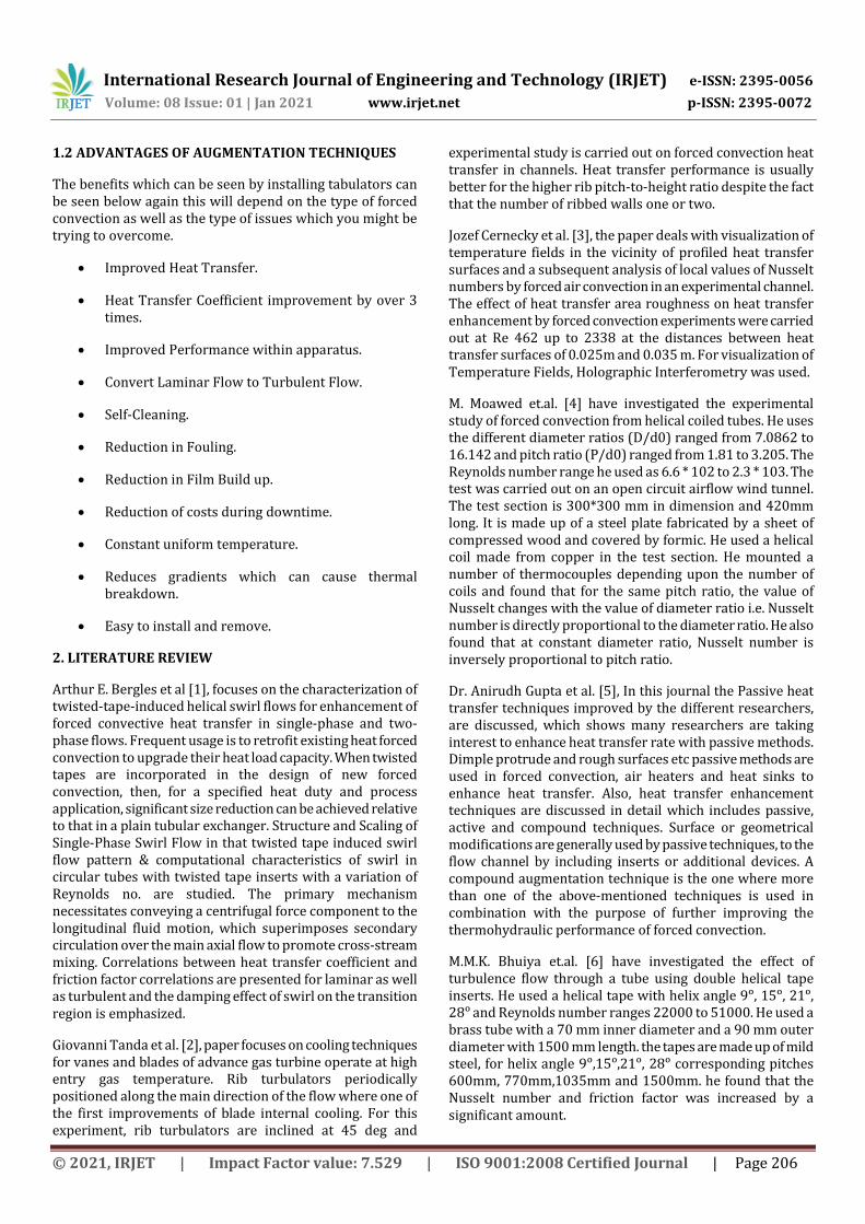
3.1.6. ARRANGEMENT FOR INSERT INSIDE THE TEST SECTION
An arrangement is made to insert the pipe with triangular fin inside the test section. For convenience, the inlet and outlet sections are made of flanged joints to simplify fixing the inserts and to achieve leak proof joints.
Fig -5: Arrangement of Pipe with Triangular Fin Insert in Test Section.
3.1.7 THE INSERT
The insert used for the experiment aluminum pipe with GI triangular fin mounted on pipe. The present work deals with finding the heat transfer coefficient.
Copper pipe ID = 20.5mm
Copper OD=25.5mm
Material of test section = Copper
Test section length= 1m
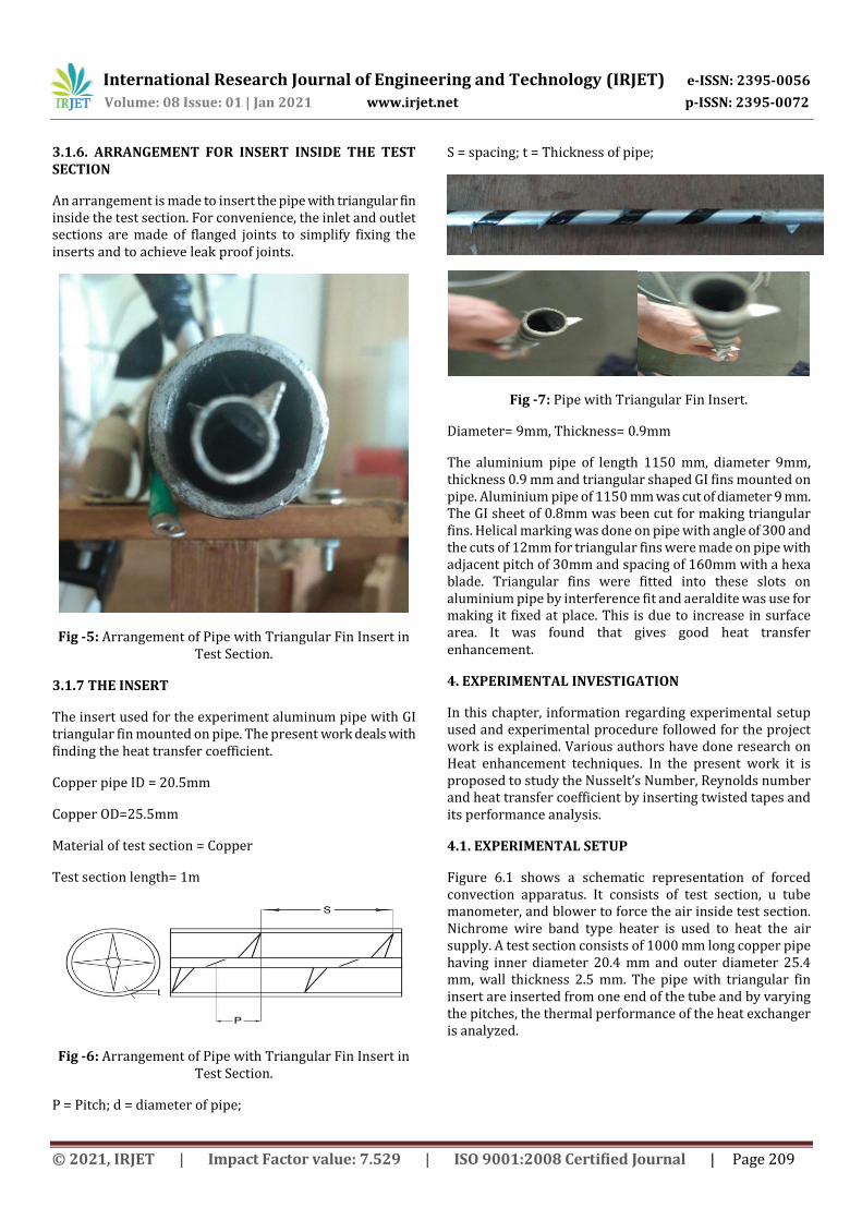
Fig -6: Arrangement of Pipe with Triangular Fin Insert in Test Section.
P = Pitch; d = diameter of pipe;
S = spacing; t = Thickness of pipe;
Fig -7: Pipe with Triangular Fin Insert.
Diameter= 9mm, Thickness= 0.9mm
The aluminium pipe of length 1150 mm, diameter 9mm, thickness 0.9 mm and triangular shaped GI fins mounted on pipe. Aluminium pipe of 1150 mm was cut of diameter 9 mm. The GI sheet of 0.8mm was been cut for making triangular fins. Helical marking was done on pipe with angle of 300 and the cuts of 12mm for triangular fins were made on pipe with adjacent pitch of 30mm and spacing of 160mm with a hexa blade. Triangular fins were fitted into these slots on aluminium pipe by interference fit and aeraldite was use for making it fixed at place. This is due to increase in surface area. It was found that gives good heat transfer enhancement.
4. EXPERIMENTAL INVESTIGATION
In this chapter, information regarding experimental setup used and experimental procedure followed for the project work is explained. Various authors have done research on Heat enhancement techniques. In the present work it is proposed to study the Nusselt’s Number, Reynolds number and heat transfer coefficient by inserting twisted tapes and its performance analysis.
4.1. EXPERIMENTAL SETUP
Figure 6.1 shows a schematic representation of forced convection apparatus. It consists of test section, u tube manometer, and blower to force the air inside test section. Nichrome wire band type heater is used to heat the air supply. A test section consists of 1000 mm long copper pipe having inner diameter 20.4 mm and outer diameter 25.4 mm, wall thickness 2.5 mm. The pipe with triangular fin insert are inserted from one end of the tube and by varying the pitches, the thermal performance of the heat exchanger is analyzed.
International Research Journal of Engineering and Technology (IRJET) e-ISSN: 2395-0056
Volume: 08 Issue: 01 | Jan 2021 www.irjet.net p-ISSN: 2395-0072
© 2021, IRJET | Impact Factor value: 7.529 | ISO 9001:2008 Certified Journal | Page 210
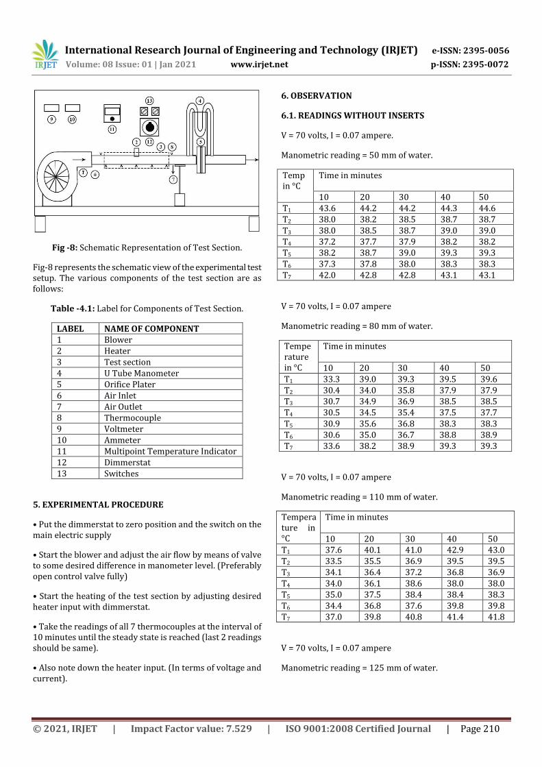
Fig -8: Schematic Representation of Test Section.
Fig-8 represents the schematic view of the experimental test setup. The various components of the test section are as follows:
Table -4.1: Label for Components of Test Section.
LABEL NAME OF COMPONENT 1 Blower 2 Heater 3 Test section 4 U Tube Manometer 5 Orifice Plater 6 Air Inlet 7 Air Outlet 8 Thermocouple 9 Voltmeter 10 Ammeter 11 Multipoint Temperature Indicator 12 Dimmerstat 13 Switches
5. EXPERIMENTAL PROCEDURE
• Put the dimmerstat to zero position and the switch on the main electric supply
• Start the blower and adjust the air flow by means of valve to some desired difference in manometer level. (Preferably open control valve fully)
• Start the heating of the test section by adjusting desired heater input with dimmerstat.
• Take the readings of all 7 thermocouples at the interval of 10 minutes until the steady state is reached (last 2 readings should be same).
• Also note down the heater input. (In terms of voltage and current).
6. OBSERVATION
6.1. READINGS WITHOUT INSERTS
V = 70 volts, I = 0.07 ampere.
Manometric reading = 50 mm of water.
Temp in °C
Time in minutes 10 20 30 40 50
T1 43.6 44.2 44.2 44.3 44.6 T2 38.0 38.2 38.5 38.7 38.7 T3 38.0 38.5 38.7 39.0 39.0 T4 37.2 37.7 37.9 38.2 38.2 T5 38.2 38.7 39.0 39.3 39.3 T6 37.3 37.8 38.0 38.3 38.3 T7 42.0 42.8 42.8 43.1 43.1
V = 70 volts, I = 0.07 ampere
Manometric reading = 80 mm of water.
Temperature in °C
Time in minutes 10 20 30 40 50
T1 33.3 39.0 39.3 39.5 39.6 T2 30.4 34.0 35.8 37.9 37.9 T3 30.7 34.9 36.9 38.5 38.5 T4 30.5 34.5 35.4 37.5 37.7 T5 30.9 35.6 36.8 38.3 38.3 T6 30.6 35.0 36.7 38.8 38.9 T7 33.6 38.2 38.9 39.3 39.3
V = 70 volts, I = 0.07 ampere
Manometric reading = 110 mm of water.
Temperature in °C
Time in minutes 10 20 30 40 50
T1 37.6 40.1 41.0 42.9 43.0 T2 33.5 35.5 36.9 39.5 39.5 T3 34.1 36.4 37.2 36.8 36.9 T4 34.0 36.1 38.6 38.0 38.0 T5 35.0 37.5 38.4 38.4 38.3 T6 34.4 36.8 37.6 39.8 39.8 T7 37.0 39.8 40.8 41.4 41.8
V = 70 volts, I = 0.07 ampere
Manometric reading = 125 mm of water.

International Research Journal of Engineering and Technology (IRJET) e-ISSN: 2395-0056
Volume: 08 Issue: 01 | Jan 2021 www.irjet.net p-ISSN: 2395-0072
© 2021, IRJET | Impact Factor value: 7.529 | ISO 9001:2008 Certified Journal | Page 211
Temperature in °C
Time in minutes 10 20 30 40 50
T1 42.3 44.8 45.1 45.2 45.2 T2 36.0 38.7 41.6 42.6 42.7 T3 36.8 39.7 41.8 43.0 43.1 T4 36.2 39.0 42.3 43.5 43.5 T5 37.8 40.9 42.6 43.7 43.9 T6 36.8 39.8 42.0 42.3 42.3 T7 41.9 43.7 44.2 44.7 44.7
6.2. READINGS WITH INSERTS
V = 70 volts, I = 0.07 ampere
Manometer reading = 50 mm of water.
Temp in °C
Time in minutes 10 20 30 40 50
T1 45.9 45.5 45.6 45.8 45.8 T2 37.7 39.6 40.1 40.3 40.2 T3 38.2 40.3 40.8 40.9 40.9 T4 38 39.6 40.3 40.5 40.4 T5 38.9 40.9 41.6 41.8 41.8 T6 38.2 40.0 40.7 40.9 40.9 T7 41.5 43.8 44.4 44.5 44.5
V = 70 volts, I = 0.07 ampere
Manometric reading = 80 mm of water.
Temperature in °C
Time in minutes 10 20 30 40 50
T1 40.2 43.2 44.0 46.4 46.4 T2 35.1 37.2 38.0 38.4 38.4 T3 35.8 38.4 39.2 39.6 39.6 T4 35.3 37.5 38.4 38.8 38.9 T5 36.4 39.0 40.2 40.8 40.8 T6 35.6 38.3 39.3 40.0 40.0 T7 39.1 42.2 43.5 44.1 44.1
V = 70 volts, I = 0.07 ampere
Manometric reading = 110 mm of water.
Temperature in °C
Time in minutes 10 20 30 40 50
T1 44.0 46.2 46.3 46.5 46.5 T2 36.7 38.8 40.7 41.8 41.9 T3 37.7 40.1 41.0 41.9 42.3 T4 37.3 39.2 42.0 42.8 44.0 T5 38.9 41.3 42.1 42.7 42.7
T6 37.9 40.3 41.0 42.3 42.9 T7 40.9 45.1 45.6 45.8 45.9
V = 70 volts, I = 0.07 ampere
Manometric reading = 125 mm of water.
Temperature in °C
Time in minutes 10 20 30 40 50
T1 45.2 47.8 48.3 48.6 48.6 T2 36.5 40.3 40.5 40.8 40.9 T3 37.2 41.1 41.9 42.1 42.1 T4 36.6 39.8 41.2 41.3 41.3 T5 37.8 41.7 42.7 43.3 43.3 T6 36.7 40.4 41.2 41.9 42.0 T7 41.2 45.5 47.2 47.5 47.5
7. SAMPLE CALCULATIONS
1)Bulk mean temperature of air,
T mean = (T1 +T7 )/2
= (44.6+43.1)/2
= 43.85 °C
2) Properties of Air at T mean ,
ρ air = 1.1131 kg/m3
CPA = 1.007 kJ/kgK
3) Surface Temperature,
T surface = (T2 + T3 +T4 +T5 +T6 )/5
= (38.7+39+38.2+39.3+38.3)/5
= 38.7 °C
4) Properties of Air at Film,
μ = Dynamic viscosity of air (Ns/m2 )
k =Thermal conductivity of air(W/mK)
5) Average Velocity of Air(m/s),
V= √( gH ...(HAir = Hwater *1000/ ρair )
=√ (2 ∗ 9.81 ∗ 44.9195)
= 29.6870 m/sec.
6) Mass flow rate of air,
m = ρair (V πr2 )Cd

International Research Journal of Engineering and Technology (IRJET) e-ISSN: 2395-0056
Volume: 08 Issue: 01 | Jan 2021 www.irjet.net p-ISSN: 2395-0072
© 2021, IRJET | Impact Factor value: 7.529 | ISO 9001:2008 Certified Journal | Page 212
Where, Cd = Coefficient of discharge
= 3 * 9 678*(π/4 *(0.022)2*0.6
=7.5367*103 kg/sec.
7) Heat flow,
Q= ma Cpa (T7 -T1 )
= 7.5367*1007*(43.1 – 44.6)
= -11.3841 W.
Q = havg (πdL *(Tsurface -Tmean )
-11.3841 = havg *π ∗ 0.0221*(38.7 – 43.89)
havg = 31.98 W/m2 °C.
8) Film Temperature,
Tfilm = (Ts +Tmean )/2 = 41.27°C
Properties of air at T film from standard air properties at 1atm pressure,
ρ = 1.1224 kg/m3
μ = 1.9238 kg/ms
Pr = 0.7251
Re = ρVd/μ
= ( 4∗ 9 44∗ / ( 9 38∗ -5 )
= 37787.50
8. RESULTS
The experimental investigation and the calculations were discussed in the previous section. Now the present section deals with interpretation of the obtained results. Effect of different Reynolds numbers on the Nusselt’s Number and performance evaluation are studied. These parameters are considered for plain tube, pipe with triangular fin. Then the comparative study was carried out which is summarized as follows.
TABLE NO.8.1:
Sr. No 1) 2) 3) 4) Tm
(°C) 43.8 39.4 42.4 44.9
Ts
(°C) 38.7 38.3 38.5 43.7
Tin
(°C) 44.6 39.6 43 45.2
Tout
(°C) 43.1 39.3 41.8 44.7
Cpa
(J/kgK) 1007 1007 1007 1007
ma
(kg/s)10-3 7.59 9.67 11.2 11.89
H (mm of water)
50 80 110 125
V (m/s)
29.4 36.9 43.9 47
H W/Km2
32.2 44.4 50.2 69.2
TF
(°C) 41.2 38.8 40.4 44.3
Re 37788 48117.2 56643.6 59329 Pr 0.7251 0.7257 0.7253 0.7242 Nu 116.9 142.62 162.61 168.7
TABLE NO.8.2:
Sr. No 1) 2) 3) 4) Tm
(°C) 45.15 45.25 46.7 48.05
Ts
(°C) 40.85 39.54 42.76 45.5
Tin
(°C) 45.8 46.4 47.5 48.6
Tout
(°C) 44.5 44.1 45.9 47.5
Cpa
(J/kgK) 1007 1007 1007 1007
ma
(kg/s)10-
3 7.52 9.52 11.1 11.8
H (mm of water)
50 80 110 125
V (m/s)
29.75 37.63 44.22 47.28
H W/Km2
33.12 55 65.67 74.41
TF
(°C) 43 42.39 44.73 46.77
Re 37817 47996.5 55666.8 58837.6 Pr 0.7246 0.7248 0.7241 0.72.36 Nu 116.93 165.69 160.26 167.53

International Research Journal of Engineering and Technology (IRJET) e-ISSN: 2395-0056
Volume: 08 Issue: 01 | Jan 2021 www.irjet.net p-ISSN: 2395-0072
© 2021, IRJET | Impact Factor value: 7.529 | ISO 9001:2008 Certified Journal | Page 213
9. GRAPHS
Graph 9.1. Heat transfer coefficient(h) v/s Nusselt Number (Nu).
Graph 9.1 shows variation heat transfer coefficient in with respect to Nusselt number. As we use insert it gives larger heat transfer coefficient which corresponds to more active convection.
Graph 9.2. Heat transfer coefficient (h) v/s Mass flow rate (m).
Graph 9.2 shows heat transfer coefficient with respect to mass flow rate. As we use inserts for different mass flow rate heat transfer coefficient increases proportionally.
Graph 9.3. Nusselt Number (Nu) v/s Reynolds Number (Re).
Graph 9.3 Shows variation of Nusselt number with respect to Reynolds number. It is also found that the variation between Nusselt number and Reynolds number is negligible. The value of heat transfer coefficient increases with increase in Reynolds number.
10. CONCLUSIONS
The convective heat transfer performance a flow characteristic of fluids flowing in a heat pipe has been experimentally investigated. The effect of Reynolds no. on the heat transfer performance and flow behavior of the fluid has been experimentally determined. Important conclusions are summarized as follows:
1. With increase in mass flow rate, Nusselt’s Number increases but at the same time pressure drop also increases.
2. Significant enhancement has been found in heat exchanger effectiveness by adopting fins on outer surface of inner tube. Good enhancement for triangular fins has been concluded within the less distance between two fins.
3. In a heat pipe, while the inserts can be used to enhance the heat transfer rate, they also bring in an increase in the pressure drop. When the pressure-drop increases, the operating cost also increases. So, depending on the requirement, one of the above mentioned for heat transfer augmentation, inserts can be used.
4. The friction factor decreases with Reynolds number increment and the friction factor in the finned tube gradually decreases with increasing distance between two fins (space = 160mm).
5. New correlations for the Nusselt number and heat transfer coefficient based on the present experimental data are given for practical uses. The agreement between the results obtained from the experimental data and those obtained from the proposed correlations is reasonable.
11. SCOPE & FUTURE
Further modifications can be done using this study as base. Some of the possibilities are mentioned below:
1. Distance between two consecutive fins can be varied and their friction factor and effect on heat transfer coefficient can easily be recorded.
2. Pressure drop is a loss of this modification, so studies can be made to minimize the pressure drop.
3. Design of inserts is also a subject to affect both the heat transfer coefficient and friction factor.
4. Experimental work can be done at low Reynolds number using viscous liquids.

International Research Journal of Engineering and Technology (IRJET) e-ISSN: 2395-0056
Volume: 08 Issue: 01 | Jan 2021 www.irjet.net p-ISSN: 2395-0072
© 2021, IRJET | Impact Factor value: 7.529 | ISO 9001:2008 Certified Journal | Page 214
5. The same experiment can also be tested with cooling operations. To enhance the heat transfer rate in forced convection. Using insert is one of the passive heat transfer enhancement techniques, which are extensively used in various heat transfer applications such as, air conditioning and refrigeration systems, food and dairy processes, heat recovery processes, chemical process plants. A small scale
12. NOMENCLATURE
Va = Air Velocity
Q = Discharge of Air
Cd = Coefficient of Discharge
A1 = Area of Pipe (Test Section)
A2 = Area of Orifice
Hm = Difference in Manometer Reading
T1 = Inlet Air Temperature
T7 = Exit Air Temperature
T2 to T6 = Temperatures of Test Section
V = Input Voltage
I = Input Current
Re = Reynolds Number
θ = Kinematic Viscosity
Nu = Nusselt Number
Pr = Prandtl Number
K = Thermal Conductivity
h = Heat Transfer Coefficient
13. REFERENCES
[1] Raj M. Manglik & Arthur E. Bergles “ haracterization Of Twisted-Tape-Induced Helical Swirl Flows For Enhancement Of Forced Convective Heat Transfer In Single-Phase And Two-Phase Flows” Fellow ASME Thermal-Fluids & Thermal Processing Laboratory, June 2013, vol. 5.
[2] Giovanni Tanda and Roberto Abram “Forced Convection Heat Transfer in Channels with Rib Tabulators Inclined at 45°” Journal of Turbo machinery fellow ASME, APRIL 2009, Vol. 131 / 021012- 1 to 10
[3] Jozef Cernecky, Jan Koniar and Zuzana Brodnianska “The Effect of Heat Transfer Area Roughness on Heat Transfer Enhancement by Forced onvection” Journal of Heat Transfer fellow ASME APRIL 2014, Vol. 136 /041901-1 to 8.
[4] M. Moawed, Experimental study of forced convection from helical coiled tubes with different parameters, Energy Conversion and Management 52 (2011)1150–1156
[5] Dr. Anirudh Gupta, Mayank Uniyal “Review of Heat Transfer Augmentation through Different Passive Intensifier Methods” IOSR Journal of Mechanical and Civil Engineering (IOSRJMCE) ISSN: 2278-1684 Volume 1, Issue 4 (July-Aug 2012), PP 14-21.
[6] M.M.K. Bhuiya, M.S.U. Chowdhury, J.U. Ahamed, M.J.H. Khan, M.A.R. Sarkar, M.A. Kalam, H.H. Masjuki, M. Shahabuddin, Heat transfer performance for turbulent flow through a tube using double helical tape inserts, International Communications in Heat and Mass Transfer 39 (2012) 818–825
[7] Naga Sarada S., Kalyani K. Radha and A. V. S. Raju, experimental investigation in circular tube to enhance turbulent heat transfer using mesh inserts, ARPN Journal of Engineering and Applied Sciences, VOL. 4, NO. 5, JULY 2009, ISSN 1819-6608
[8] Amnart Boonloi, Withada Jedsadaratanachai, Turbulent Forced convection and Heat Transfer Characteristic in a Circular Tube with Modified-Twisted Tapes, Hindawi Publishing Corporation Journal of thermodynamics Volume 2016, Article ID 8235375
[9] S.G. Mushan, B.E. Patil, N.K. Sane, D.V. Ghewade, heat augmentation using non-metallic insert sin forced convection, IOSR Journal of Mechanical and Civil Engineering (IOSR-JMCE) e-ISSN: 2278-1684, p-ISSN: 2320-334X
[10] Suhas V. Patil and P. V. Vijay Babu “Heat Transfer Augmentation in a Circular tube and Square duct Fitted with Swirl Flow Generators: A Review” International Journal of Chemical Engineering and Applications, Vol. 2, No. 5, October 2011
[11] Kurhade Anant Sidhappa, Sonal S. Hande, Swarup B. Patil, Vivekanand R. Maske, heat transfer enhancement by using twisted tape inserts with circular holes in forced convection, international journal of innovations in engineering research and technology [IJIERT], ISSN: 2394-3696, Volume 3, ISSUE3, MAR.-2016
[12] A Dewan, P Mahanta, K Sumithra Raju & P Suresh Kumar, “Review of passive heat transfer augmentation techniques”, Proc.Instn Mech. Engrs. Vol. 218 Part A: J Power & Energy, (2004), 509-527.
[13] Kreith F., Timmerhaus K., Lior N., Shaw H., Shah R.K., Bell K. J. etal. “Applications ” The CRC Handbook of Thermal Engineering. Ed. Frank Kreith. Arthur E. Bergles. Boca Raton: CRC Press LLC, 2000, 408-457.
[14] Sajjad Bouzari, Jafar Ghazanfarian, forced convection over cylinder with radial fins in cross flow, International Journal of Heat and Mass TransferS1359-4311(16)32294-3
[15] P.S. Desale, N.C. Ghuge, heat transfer enhancement using coiled wire inserts in horizontal concentric tubes, international journal of innovations in engineering research and technology [IJIERT], ISSN: 2278-6082, Volume 1, ISSUE2, July-2012.