analysis of a novel high performance induction air heater
TRANSCRIPT
Unver, U., et al.: Analysis of a Novel High Performance Induction air Heater THERMAL SCIENCE: Year 2018, Vol. 22, Suppl. 3, pp. S843-S853 S843
ANALYSIS OF A NOVEL HIGH PERFORMANCE INDUCTION AIR HEATER
by
Umit UNVER *a, Ahmet YUKSEL a, Alper KELESOGLU a, Fikret YUKSEL a, and Halil Murat UNVER b
a Department of Energy Systems Engineering, Yalova University, Yalova, Turkey b Department of Computer Engineering, Kirikkale University, Kirikkale, Turkey
Original scientific paper https://doi.org/10.2298/TSCI170913018U
This study represents an experimental and numerical investigation of the enhanced prototypes of the induction air heaters. For this purpose, flow field is enhanced in order to avoid turbulence. The air mass flow rate, outlet construction and the application of insulation of the outer surface of the heater were selected as the performance enhancing parameters. Depending on the exit construction, the new designed prototypes are named as K-2 and K-3. Experiments were performed un-der two groups for three various flow rates. In the first group, non-insulation situ-ation is examined. In the second group tests, insulation is applied to the outside of windings and inlet-outlet flaps which constitute the boundary of the control volume for the prevention of heat losses. The increasing flow rate boosted the thermal efficiency by 9%. Each of insulation and enlarging exit cross section increased the thermal efficiency by 13%. It was observed that the thermal power transferred to air with the new prototypes in-creased about 246 W more than the previous designs. The thermal efficiencies of the K-2 and K-3 type heaters were calculated as 77.14% and 87.1%, respectively.Key words: induction, air heater, induction fluid heater, thermal analysis, CFD,
energy efficiency
Introduction
The studies about energy efficiency are significantly increasing with respect to the in-creasing demand [1, 2]. Therefore, the effective usage of energy became important in addition to the researching alternative energy resources [3, 4]. In a fact sheet of the European Commission, it says that heating and cooling application held 50% of annual energy consumption of Europe in 2016. The main resources for heating and cooling applications and their percentages are; natural gas (46%), coal (15%), biomass (11%), fuel oil (10%), nuclear energy (7%), renewable energy sources (mainly solar, wind and hydropower, about 5%) and other renewables and fossil fuels [5]. In the field of residential, industrial or public space heating applications, there are many options to supply heat and using various technologies. These main technologies can be classified as; heat pumps, resistance, gas-fired, solar, infrared and biomass fired space heaters, and the induction air heaters which are considered in this study [6-9]. All of these technologies have advantages for specific purposes. The electrical resistance heaters are one of the oldest solutions for residential space heating. It can convert electrical energy to the thermal energy efficiently. Solanki et al. [10]
* Corresponding author, e-mail: [email protected]

Unver, U., et al.: Analysis of a Novel High Performance Induction air Heater S844 THERMAL SCIENCE: Year 2018, Vol. 22, Suppl. 3, pp. S843-S853
performed simulations to test the hybrid solar collector which mounted on a wooden channel. They found the electrical and thermal efficiencies of the hybrid collector 8.4% and 42%, respec-tively. Ali et al. [11] investigated double pass solar air heater system to find the best efficiency. For this purpose, they run their experiments under four different configurations. They used an absorber plate, added paraffin wax as a thermal storage medium, put aluminium and steel rods as a thermal enhancer. They have concluded that the third configuration showed the best performance with 96% efficiency. Turanjanin et al. [12] made the energy and economy analysis for different home heating systems using TRNSYS simulation cod. They have compared the heating systems which use natural gas for boiler and pellet as a heat source for direct heating (biomass boiler) or heat source for a heat pump. They have considered the life time of all heating systems as 15 years. Considering the life time for all systems, their results showed that, heating with gas boiler is the best economical system. However, in the perspective of energy usage, the heat pump showed the best performance. Furthermore, Kewou et al. [13] implied that the usage of air in industrial drying process employs up to 15% of all industrial energy with low thermal efficiency between 25-50% .The literature given here are good and illuminating studies on space heating. But none of them considers the induction air heating as an alternative.
The induction theory was first introduced by Michael Faraday in 1831. After the discov-ery of induction theory, the studies made by Lenz and Neumann in 1845 showed that the induced voltage heats the conductive material [14]. The usage of induction in many industrial processes such as preheating, surface hardening and tempering were increased due to its economic ease of usage in recent days [15]. Nowadays, the induction heating systems considered as the competi-tors to the natural gas fired furnaces in terms of energy consumption and size are also frequently encountered in the domestic applications. It is also possible to find induction in many different heating processes, such as sterilization of medical equipment, asphalt heating and etc. [16].
Induction heating systems are widely used in metal heating processes because of their many advantages such as being environmentally friendly system, short application time and low thermal losses [17]. It has been implied that a more economic and ergonomic system can be ob-tained by incorporating induction heaters in the extrusion process of aluminium materials [18]. Luo and Shih [19] found the heat flux that supplied from the induction heater by using the thermal changes in the single-carbon steel as a working material. Nian et al. [20] used the induction heater to heat the mould surface. Pleshivtseva et al. [21] investigated the usage of induction in preheating of metals before hot forming. Tavakoli et al. [22, 23] studied the effect of workpiece dimensions on induction heating. On the other hand, the differences between gas fired furnaces and induction heaters have investigated [24]. The literatures given in this paragraph provide useful insight into induction heating of metals. But they are not concerned with fluid heating.
Curran and Featherstone implied that induction can be used for fluid heating appli-cations as it used in metal heating processes [25]. Induction liquid heaters have become to compete with resistive liquid heaters with the expansion of the field of application [26]. Kole-snikov and Andreev [27] investigated the heat transfer characteristics of a fluid flow inside the ring-shaped metal channel by applying a magnetic field. Altintas et al. [28] designed a micro-controller based induction liquid heater. On the other hand, induction heaters have domestic applications as well as industrial applications. Acero et al. [29, 30] improved and characterized the resistance and power consumption of induction by placing between two planes for the kitchen applications. Fenercioglu and Kartal [31] used Eddy currents which forms the basis of induction for decomposition of non-ferrous metals. Cetin [32] designed and analysed a kitchen type induction heating system in his master thesis. Induction heating systems are also used for polymerization, bitumen heating and sterilization [33-35].

Unver, U., et al.: Analysis of a Novel High Performance Induction air Heater THERMAL SCIENCE: Year 2018, Vol. 22, Suppl. 3, pp. S843-S853 S845
Using induction heating for the purpose of air heating was introduced by Burnett [36, 37] who prioritized the investigation of the transformer and coil sections of the developed induction gas heater systems. After this invention, Virgin [38] dealt with the electrical discipline of the system called the electromagnetic induction air heater and described the system as a steam-generating energy converter at the basis of his study. Similarly, Iguchi supported the idea that explained as in [38], however he did not include the thermal analysis in the study [39]. De-spite the fact that the research and application area of induction heaters has such a wide variety, the electrical discipline of the systems has been taken into consideration in the studies for fluid heating. Additionally, the air heating process and the examination of thermal analysis have not been satisfactorily analysed in the literature [40].
In this paper, the thermodynamic analysis of the induction air heater system was per-formed. The system is developed to be an alternative to supply hot air requirement for fruit and vegetable drying processes such as in [41, 42]. In addition, the suggested improvement alternatives were made in the system that previously described as K-0 and K-1 type prototypes [43]. Following the suggestions, the constructions named K-2 and K-3 was developed and their dimensions were given in the next section. As a result, the decrease in thermal losses and hence the increase in thermal efficiency is ensured. In addition, the experimental results were exam-ined and the CFD analysis was performed to determine the accuracy of the results.
Material and method
Thermal analysis
In this study, the modifications for the thermal development of the induction air heat-ing system have been experimentally and numerically investigated. The experiments for each prototype were performed under two groups (insulated and uninsulated), considering three dif-ferent flow rates. In the first group tests, uninsulated situation is examined. In the second group tests, insulation is applied to the outside of windings and inlet-outlet flaps which constitute the boundary of the control volume for the prevention of heat losses. The system was evaluated as steady flow system and thermal analysis was performed according to 1st Law of Thermodynam-ics. The inlet part of the induction air heating system is designed to be conical in dimensions of 140 × 68.5 mm with a length of 129 mm. K-2 type heater outlet is designed as conical in dimensions of 140 × 90 mm and K-3 type heater outlet is designed according to ASME B 16.9 standard, in dimensions of 140 × 114 mm as a concentric reducer as seen in fig. 1. Inside of the shell was considered as the control volume boundary. The induction heating system cannot transfer entire the electrical energy from the coils to the air due to the heat losses from the sur-face of the shell that are; radiation and natural convection. In this study, the procedure given
Outlet
capWindings Shell
Inlet
cap
Figure 1. Experimental rig and the schematic view of K-2 and K-3 type induction air heater prototype
Power
Transformer

Unver, U., et al.: Analysis of a Novel High Performance Induction air Heater S846 THERMAL SCIENCE: Year 2018, Vol. 22, Suppl. 3, pp. S843-S853
by reference [44] for natural convection and radiation heat losses were applied. The magnitude of the radiation loss was calculated with the average of the surface temperature measured via a thermal imager. Since the control volume is accepted as the inner side of the shell, the boundary conditions can be accepted as constant heat flux from the sides and steady flow from the both ends. At the beginning of the experiments the system boundaries are at the room temperature and at the end of the experiments the side boundary of the system is at the inner temperature of the shell. During the entire process, heat flux and the mass flow rate assumed constant.
Other parameters that cause energy losses in the induction air heater are kinetic ener-gy variation and friction-discharge losses. Although these losses are small, proportional to the size of the working system, they may cause too much energy loss when the system sizes are increased.
The fluctuations in the fluid density cause changes in the velocity of the fluid and its’ kinetic energy. The kinetic energy difference can be calculated:
( )2 212KE o iP m V V∆ = −
(1)
where Δ PKE [W] is the kinetic energy difference, Vo [ms–1] – the outlet velocity of the air and Vi [ms–1] – the inlet velocity of the air.
The amount of heat transferred to the fluid increases depending on the roughness coefficient of the surface in the system. However, resistance of the solid surface limits the fluid movement. This limitation is reflected in the system as friction losses. In addition to friction losses, there are partial losses at the connection points of the parts, such as inlet-outlet caps and in the areas where the cross-section changes. Such losses are called local losses. Within the scope of this study, the losses are also referred to as discharge losses. The discharge losses are obtained by the sum of friction and local losses and can be expressed in eq. (2) [33].
2
g 2gDL D
L VP f CD
ρ ∆ = +
(2)
Here ΔPDL, f, L, and CD represents discharge losses [W], friction factor, pipe length [m] and discharge loss coefficient, respectively. The total loss from the system can be calculated:
rad otherL nc DLP Q Q P PΣ = + + ∆ + (3)
Here PL [W], refers to the total power loss of the system, and is the loss due to leakage. It is necessary to know the induction power fed to the system in order to calculate the thermal efficiency which is the main aim of the work. For this reason, electrical power that was obtained experimentally is converted to the thermal power that is induced in the coil by using induction efficiency as given in eq. (4). b ind indP P η= (4)
Here Pind [W], refers to the induction power, is the amount of power that is rejected from the coil, and is the induction efficiency [45]. In the analysis, the thermal efficiency of the system was defined as the ratio of the power transferred to the air by the electric power reaching the inductor:
air
thb
QP
η =
(5)

Unver, U., et al.: Analysis of a Novel High Performance Induction air Heater THERMAL SCIENCE: Year 2018, Vol. 22, Suppl. 3, pp. S843-S853 S847
Since the steady-flow conditions of the system were evaluated in the study, eq. (6) was employed to assess the steady-flow [15]:
( )n1 2i 0.3i iT T
Tn iε− −−
∆ = <−
∑ (6)
Table 1. Measurements and instrument specificationItem Instrument Range Accuracy
Temperature measurements
Multi-channel thermometer with K-type thermocouple, Data logger –100-1300 °C ± 0,7 °C,
± 0,1% readingVelocity
measurement Testo 410-2 anemometer 0,4-20 m /s ±0.2 m/s, ± 2% measured value
Temperature distribution measurement Testo 875 thermal camera 0-350 °C ±2 °C, ±2% of
measured value
Power measurements Brymen BM-157 clamp meter 0-600 kW ±4,5%, + 6 digits
The flow rate is adjusted by a valve placed in the inlet of the test apparatus. In order to prevent heat losses the control volume that is the outside of the shell, inlet and outlet caps are insulated. The results were compared with K-0 and K-1 type induction heaters and confirmed with CFD analysis.
The measurement range is set to 5 minutes after a steady-flow is achieved. The devic-es given in tab.1 were used for the measurements. The uncertainty was calculated as 5.7% for K-2 experiments and 8.1% for K-3 experiments.
Numerical modelling
The induction heater was modelled with 2-D-axisymmetric model due to symmetrical geometry as shown in fig. 1. The diameter and length of the shell are considered 140 mm and 450 mm, respectively. The inductor which has 374 windings and inner and outer diameters, 160 mm and 237 mm, are introduced to the model. The surrounding air of the heater sys-tem also included to the geometry. The result-ing geometry of the K-2 type prototype can be seen in fig. 2.
The materials of inductor, shell and iso-lations were selected as copper, ST-52 steel, glassfiber and temperature resistance thermoplas-tic, respectively. The thermophysical properties of the materials were introduced as a tempera-ture dependent as indicated in Cheng et al. [46] and Hadjab and Kadja [47].
The non-isothermal flow and induction heating are selected as a main physics. The sub-physics are as follows: the magnetic fields, heat transfer in solids, heat transfer in fluids and turbulence flow (k-ε). The power measured from the experiments was introduced to the inductor as a boundary condition. On the other hand, the mass flow rate that obtained from the experiments was introduced to the model to solve the Navier-Stokes equations. The inlet tem-perature of the air was taken as ambient temperature in the heat transfer equations. The physics
Heated
air
Shell Insulation Windings Ambient
air
Figure 2. The K-2 type geometry for the simulation
Unver, U., et al.: Analysis of a Novel High Performance Induction air Heater S848 THERMAL SCIENCE: Year 2018, Vol. 22, Suppl. 3, pp. S843-S853
controlled normal quality mesh that is automatically generated by the simulation program (tri-angular elements) was used to solve the model and the mesh size is selected as extremely fine.
Results and discussion
The K-2 and K-3 heaters were designed according to avoid disturbing the flow. The inlet and the exit sections are widened and the effect of the change of the inlet and exit construc-tion on the performance was investigated experimentally. The experiments were performed for insulated and uninsulated cases with 3 various flow rates. The effect of insulation and the flow rate were also observed.
Investigation of flow rate effect
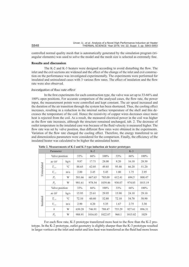
In the first experiments for each construction type, the valve was set up to 33-66% and 100% open positions. For accurate comparison of the analysed cases, the flow rate, the power input, the measurement points were controlled and kept constant. The air speed increased and the duration of the air transition through the system has been shortened. Thus, the cooling effect increases, resulting in a reduction in the internal surface temperature of the shell and this de-creases the temperature of the coil. Hence the resistivity of copper wires decreases since more heat is rejected from the coil. As a result, the measured electrical power in the coil was higher as the flow rate increases, although the structure remained unchanged, tab. 2. The decrease of outlet temperature in the insulated case was because of the fluid velocity is measured higher. The flow rate was set by valve position, thus different flow rates were obtained in the experiments. Variation of the flow rate changed the cooling effect. Therefore, the energy transferred to air and dimensionless parameters were considered for the comparison. Finally, the efficiency of the insulated heater was calculated to be higher the uninsulated heater.
Table 2. Measurements of K-2 and K-3 type induction air heater prototypesParameter K-2 K-3
Uni
nsul
ated
Valve position 33% 66% 100% 33% 66% 100%
ṁ⋅103 kg/s 9.87 17.71 28.00 8.20 16.10 28.50
To, a °C 88.65 62.05 49.85 95.40 66.20 51.20
Vo, a m/s 2.00 3.45 5.45 1.00 1.75 2.95
Pb W 581.66 667.63 785.09 612.41 694.5 800.47
Pg W 981.61 978.54 1039.46 930.07 974.85 1015.19
Insu
late
d
Valve position 33% 66% 100% 33% 66% 100%
ṁ⋅103 kg/s 15.95 23.61 29.95 15.90 24.10 29.10
To, a °C 72.10 60.60 52.80 72.10 54.70 50.90
Vo, a m/s 2.90 4.20 5.35 1.67 2.75 3.30
b W 650.28 746.91 788.47 755.29 827.61 896.31
Pg W 988.91 1016.83 1022.07 960.1 1015.02 1029
For each flow rate, K-3 prototype transferred more heat to the flow than the K-2 pro-totype. In the K-2 prototype, outlet geometry is slightly sharper than the K-3 prototype resulted in larger vortices at the inlet and outlet and less heat was transferred as the fluid had more losses

Unver, U., et al.: Analysis of a Novel High Performance Induction air Heater THERMAL SCIENCE: Year 2018, Vol. 22, Suppl. 3, pp. S843-S853 S849
in the shell. As a result, the cooling effect of the fluid on the shell was less and the overall temperature of the system was more.
Effect of insulation on the thermal losses
The insulation reduces the thermal losses from the outer shell, fig. 3. It was ob-served that according to the uninsulated case, the insulation application saves 115.21 W and 121.28 W in K-2 and K-3, respectively.
The total heat losses from all proto-types developed so far were compared with each other. The least total heat loss is calcu-lated to be from K-3 prototype. This results shows that enhancing the flow field has a pos-itive effect on thermal losses.
Investigation of construction
The CFD analysis of induction heater designs, flow rate and internal temperature distributions were performed by using a model that has validated in [43]. In the model, the velocity of the air decreased when the outlet construction of the shell was widened as seen in fig. 4. Although the K-2 type heater evacuated the air faster than the K-3 type heater at the same flow rate, the air outlet temperature was found to be close to both types of heater.
According to the CFD analysis, the velocity of the fluid in the K-3 construction was found to be slower through the shell than in the K-2 type as shown in fig. 5. That is, the vor-texes formed in the K-2 type heater are denser than the vortices in the K-3, thus the inner wall temperature distribution is became higher.
The temperature distribution along the centre axis is also higher in the K-2 type heater than in the K-3. In the K-3 heater, the speed and therefore the kinetic energy is low, so that the thermal energy transferred from the system to the air is relatively more.
The air leaves the system after transferring the heat from the inner wall of the shell. The increase in flow rate in the system increases the cooling effect of the air and provides more heat transfer. However, as the energy transferred to the unit mass decreases, the average air outlet temperature and total heat transfer increase, resulting in lower wall temperatures. How-ever, despite the increase in the average air outlet temperature and the total heat transfer, the
Thermal losses [W]
Natural convection Radiation
Figure 3. Natural convection and radiation losses of K-2 and K-3 type prototypes with/ without insulation
K2 velocity K3 velocity K2 temperature K3 temperature
Ve
loci
ty [
ms
]–
1
Tem
pe
ratu
re [°C
]
Length [mm]
Velocity magnitude [m/s]
9
8
7
6
5
4
3
2
1
Figure 4. Temperature and velocity variations through the centreline
Figure 5. Velocity contours of K-2 and K-3 type prototypes for non-insulation condition
Unver, U., et al.: Analysis of a Novel High Performance Induction air Heater S850 THERMAL SCIENCE: Year 2018, Vol. 22, Suppl. 3, pp. S843-S853
wall temperature of the shell became lower because the energy transferred to the unit mass was decreased.
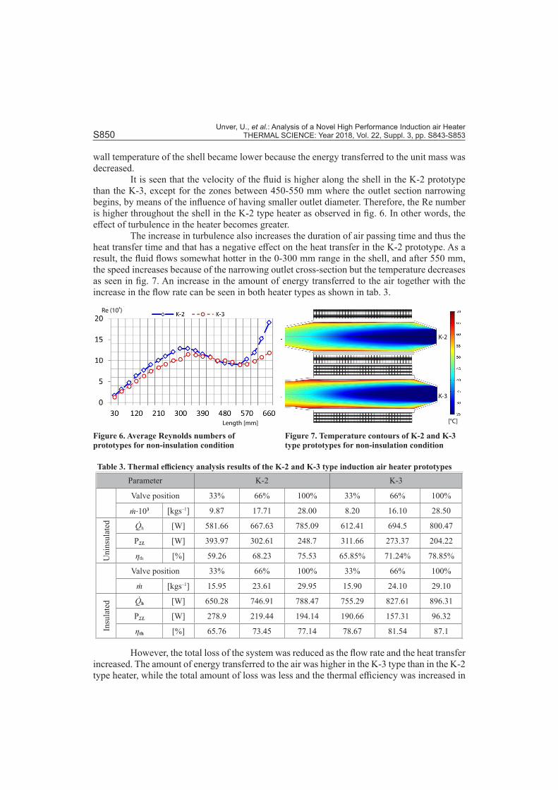
It is seen that the velocity of the fluid is higher along the shell in the K-2 prototype than the K-3, except for the zones between 450-550 mm where the outlet section narrowing begins, by means of the influence of having smaller outlet diameter. Therefore, the Re number is higher throughout the shell in the K-2 type heater as observed in fig. 6. In other words, the effect of turbulence in the heater becomes greater.
The increase in turbulence also increases the duration of air passing time and thus the heat transfer time and that has a negative effect on the heat transfer in the K-2 prototype. As a result, the fluid flows somewhat hotter in the 0-300 mm range in the shell, and after 550 mm, the speed increases because of the narrowing outlet cross-section but the temperature decreases as seen in fig. 7. An increase in the amount of energy transferred to the air together with the increase in the flow rate can be seen in both heater types as shown in tab. 3.
Table 3. Thermal efficiency analysis results of the K-2 and K-3 type induction air heater prototypesParameter K-2 K-3
Valve position 33% 66% 100% 33% 66% 100%
ṁ⋅103 [kgs–1] 9.87 17.71 28.00 8.20 16.10 28.50
Uni
nsul
ated Q̇h [W] 581.66 667.63 785.09 612.41 694.5 800.47
PƩL [W] 393.97 302.61 248.7 311.66 273.37 204.22
ηth [%] 59.26 68.23 75.53 65.85% 71.24% 78.85%
Valve position 33% 66% 100% 33% 66% 100%
ṁ [kgs–1] 15.95 23.61 29.95 15.90 24.10 29.10
Insu
late
d Q̇h [W] 650.28 746.91 788.47 755.29 827.61 896.31
PƩL [W] 278.9 219.44 194.14 190.66 157.31 96.32
ηth [%] 65.76 73.45 77.14 78.67 81.54 87.1
However, the total loss of the system was reduced as the flow rate and the heat transfer increased. The amount of energy transferred to the air was higher in the K-3 type than in the K-2 type heater, while the total amount of loss was less and the thermal efficiency was increased in
Re (10 )4
Length [mm] [°C]
K-2
K-3
Figure 6. Average Reynolds numbers of prototypes for non-insulation condition
Figure 7. Temperature contours of K-2 and K-3 type prototypes for non-insulation condition
Unver, U., et al.: Analysis of a Novel High Performance Induction air Heater THERMAL SCIENCE: Year 2018, Vol. 22, Suppl. 3, pp. S843-S853 S851
parallel with the expansion of the outlet cross section at each flow rate. Likewise, the amount of energy transferred to the air was increased at each flow rate and thus the thermal efficiency was increased while the total amount of loss was reduced by insulation application in K-2 and K-3 type heaters.
The total losses in the K-0 and K-1 induction heaters for the uninsulated cases were given as 830.8 W and 457.1 W, respectively [15, 43]. These values were reduced to 393.97 W and 311.66 W in the prototype K-2 and K-3 in the uninsulated case. The thermal efficiency, which was calculated to be 29.09% for the K-0 type and 56.3% for the K-1 type heater, is in-creased to 77.14% for the K-2 prototype and 87.1% for the K-3 prototype due to regulation of the flow field and insulation improvements.
Conclusions
The object of this study is to investigate the effects insulation and flow field en-hancement on the performance of the induction air heaters. The new heater prototypes (K-3 and K-4) were designed as a blank shell and the exit of the shell was extended so as not to disturb the air flow according to earlier prototypes. The sharp inlet and exit are preferably curved appropriately.
The experiments for insulated and uninsulated cases were repeated for 3 different flow rates according to the inlet valve position. It was observed that the flow rate, the enlarged exit cross section and the insulation increase the thermal efficiency between 3-9%, 3-13%, and 2-13%, respectively. The thermal power that is transferred to the air increased by an average of 246 W with the flow rate increment and insulation. The min. total loss and the max. thermal efficiency were calculated to be 96.32 W and 87.1% respectively in the K-3 heater through the prototypes developed so far.
For further studies, it is recommended to re-design and repeat the tests with different geometric structures and shell types with different materials. We forecast that the thermal effi-ciency may be increased if the exit and inlet diameters are made equal and the air flows both inside and outside of the coil to cool the windings. Finally, it is estimated that induction heating systems can also be used for hygienic air supply if the inner surface is appropriately coated.
Acknowledgment
This study was granted by University of Yalova Scientific Research Coordination Unit with the Project No:2015/YL/059. We would like to thank I. Muzaffer UNVER from KEMAS Co. and Mehmet OZDESLIK from Sistem Teknik Co. for their valuable contributions in this study.
References[1] Dogan, H., Yılankırkan, N., Turkey’s Energy Efficiency Potential and Projection, Gazi University Journal
of Science and Technology Part C: Design and Technology, 3 (2015), 1, pp. 375-383[2] Kumar, M., Das R. K., Experimental Analysis of Absorption Refrigeration System Driven by Waste Heat
of Diesel Engine Exhaust, Thermal Science, On-line first, https://doi.org/10.2298/TSCI160311003K[3] Ay, I., Khanlari, A., Working Principles of the Solar Wall System and Its Viability in Turkey, Gazi Univer-
sity Journal of Science and Technology Part C: Design and Technology, 3 (2015), 3, pp. 525-533[4] Harmati, N. L, et al., Energy Performance Modelling and Heat Recovery Unit Efficiency Assessment of
an Office Building, Thermal Science, 19 (2015), 3, pp. 865-880[5] ***, European Commission, http://www.europa.eu[6] Sugantharaj Gnanadurai, S. S., et al., Performances of Packed Bed Double Pass Solar Air Heater with
Different Inclinations and Transverse Wire Mesh with Different Intervals, Thermal Science, 20 (2016), 1, pp. 175-183
Unver, U., et al.: Analysis of a Novel High Performance Induction air Heater S852 THERMAL SCIENCE: Year 2018, Vol. 22, Suppl. 3, pp. S843-S853
[7] Ali, M., et al., Combining the Demand Response of Direct Electric Space Heating and Partial Thermal Storage Using LP Optimization, Electric Power Systems Research, 106 (2014), Jan., pp. 160-167
[8] Aissa, W., et al., Performance of Solar Dryer Chamber Used for Convective Drying of Sponge-Cotton, Thermal Science, 18 (2014), Suppl. 2, pp. S451-S462
[9] Jaeger, H., et al., Opinion on the Use of Ohmic Heating for the Treatment of Foods, Trends in Food Sci-ence & Technology, 55 (2016), Sept., pp. 84-97
[10] Solanki, S. C., et al., Indoor Simulation and Testing of Photovoltaic Thermal (PV/T) Air Collectors, Ap-plied Energy, 86 (2009), 11, pp. 2421-2428
[11] Ali, H. M., et al., An Experimental Investigation of Performance of a Double Pass Solar Air Heater with Thermal Storage Medium, Thermal Science, 19 (2015), 5, pp. 1699-1708
[12] Turanjanin, V. M., et al., Different Heating Systems for Single Family House Energy and Economic Anal-ysis, Thermal Science, 20 (2016), Suppl. 1, pp. S309-S320
[13] Kewou, S., et al., Numerical Simulation of Convective Heat Transfer in Channel With Corrugated Walls, Thermal Science, 22 (2016), 1, pp. 87-100
[14] Rudnev, V., et al., Handbook of Induction Heating, Marcel Dekker, New York, USA, 2003[15] Unver, U., Efficiency Analysis of Induction Air Heater and Investigation of Distribution of Energy Losses,
Tehnički Vjesnik /Technical Gazette, 23 (2016), 5, pp. 1-9[16] Kuzmichev, A., Tsybulsky, L., Evaporators with Induction Heating and Their Applications, in: Advances
in Induction and Microwave Heating of Mineral and Organic Materials (Ed. S. Grundas), In Tech Press, New York, USA, 2011, pp. 269-302
[17] Unver, H. M., Aydemir, M. T., Power and Frequency Control in a 60 kW Induction Steel Heating Furnaces Through PLC, Proceedings, National Scientific Meetings, Ankara, Turkey, 2002, Vol. 1, pp. 36-39
[18] Beer, S., Gunter, U., Combined Log Heating Furnace Inline Concept for Aluminium Extruders, Induction Technology, in: Heat Processing (Ed. B. Nacke), Vulkan-Verlag, Essen, Germany, 2012, pp. 77-80
[19] Luo, J., Shih, A. J., Inverse Heat Transfer Solution of the Heat Flux Due to Induction Heating, Journal of Manufacturing Science and Engineering, 127 (2005), 3, pp. 555-563
[20] Nian, S. C., et al., Enhancement of Induction Heating Efficiency on Injection Mold Surface Using a Nov-el Magnetic Shielding Method, International Communications in Heat and Mass Transfer, 50 (2014), Jan., pp. 52-60
[21] Pleshivtseva, Y., et al., Special Method of Parametric Optimization of Induction Heating Systems, Pro-ceedings, International Scientific Colloquium Modelling for Electromagnetic Processing, Hannover, Ger-many, 2008, Vol. 1, pp. 229-234
[22] Tavakoli, M. H., et al., Computational Modelling of Induction Heating Process, Progress in Electromag-netics Research Letters, 11 (2009), Dec., pp. 93-102
[23] Tavakoli, M. H., et al., Influence of Workpiece Height on the Induction Heating Process, Mathematical and Computer Modelling, 54 (2011), 1-2, pp. 50-58
[24] Unver, U. Unver, H. M., Comparison of Natural Gas Fired and Induction Heating Furnaces – Part VI: Fuels and Combustion, in: Progress in Exergy, Energy, and the Environment (Eds. Dincer, I., Midilli, A., Kucuk, H.,), Springer International Publishing, New York, USA, 2014, pp. 1009-1016
[25] Curran, J. S., Featherstone, A .M., Electric-Induction Fluid Heaters, Power Engineering Journal, 2 (1988), 3, pp. 157-160
[26] Manuel, G., Khan, M. T. E., Design of an Induction Heating Domestic Water Heater System, M. Sc. the-sis, Cape Peninsula Technology University, Cape Town, South Africa, 2009
[27] Kolesnikov, Y. B., Andreev, O. V., Heat-Transfer Intensification Promoted by Vertical Structures in Closed Channel under Magnetic Field, Experimental Thermal and Fluid Science, 15 (1997), 2, pp. 82-90
[28] Altintas, A., et al., Design of a Microcontroller Based Liquid Heater Operating with the Principle of In-duction Heating (in Turkish), Journal of the Institute of Science and Technology of Dumlupınar, (2012), 29, pp. 45-52
[29] Acero, J., et al., Enhancement of Induction Heating Performance by Sandwiched Planar Windings, Elec-tronics Letters, 42 (2006), 4, pp. 241-242
[30] Acero, J., et al., Experimental Setup for Inductive Efficiency Measurements of Domestic Induction Sys-tems Based on Energy Balance, Proceedings, 36th Annual Conference on IEEE Industrial Electronics Society, Glendale, Cal., USA, 2010, Vol.1, pp.114-119
[31] Fenercioglu, A., Kartal, A., Determination of Recycling Performance of Some Non-Ferrous Metals via Prototype Eddy Current Separator, Journal of the Faculty of Engineering and Architecture of Gazi Uni-versity, 30 (2015), 2, pp. 155-161

Unver, U., et al.: Analysis of a Novel High Performance Induction air Heater THERMAL SCIENCE: Year 2018, Vol. 22, Suppl. 3, pp. S843-S853 S853
[32] Cetin, S., Analysis and Design of an Single Phase Induction Heating System, M. Sc. thesis, Pamukkale University, Pamukkale, Turkey, 2005
[33] Lucia, O., et al., Induction Heating Technology and Its Applications, Past Developments, Current Tech-nology and Future Challenges, IEEE Transactions On Industrial Electronics, 61 (2014), 5, pp. 2509-2520
[34] Makimura, Y., et al., Superheated Steam Generator by Induction Heating, Proceedings, 13th European Conference on Power Electronics and Applications, Barcelona, Spain, 2009, Vol. 1, pp. 1-4
[35] Bera, A., Babadagli, T., Status of Electromagnetic Heating for Enhanced Heavy Oil/Bitumen Recovery and Future Prospects, A Review, Applied Energy, 151 (2015), Aug., pp. 206-226
[36] Burnett, H. J., Induction Gas Heater, Patent No. 3,534,197, United States Patent Office, Filed June 1, 1966, Ser. No. 554,955, 1970
[37] Burnett, H. J., Electric Induction Gas Heater, Patent No. 3,671,715, United States Patent, Filed June 1, 1970, Appl. No. 42,324, 1972
[38] Virgin, G. C., Electromagnetic Induction Air Heater, Patent No. 4,503,305, United States Patent, Filed Jan. 15, 1982, Appl. No. 339,408, 1985
[39] Iguchi, A., Electromagnetic Induction Heater, Patent No. 5,237,144, United States Patent, Filed Jun. 17, 1991, Appl. No. 716,105, 1993
[40] Unver, U., Yuksel, A., Experimental Investigation of Transient Condition of Induction Air Heating, Erz-incan University Journal of Science and Technology, 9 (2016), 2, pp. 112-125
[41] Gurel, A. E., et al., Examination of Drying Parameters of Fruits and Vegetables, Gazi University Journal of Science and Technology Part C: Design and Technology, 4 (2016), 4, pp. 267-273
[42] Aktas, M., et al, Orange Peel Drying in a Heat Pumped Dryer, Gazi University Journal of Science and Technology Part C: Design and Technology, 2 (2014), 2, pp. 229-238
[43] Unver, U., et al., Experimental Analysis of Construction Parameters on Thermal Efficiency of Induction Air Heaters, Proceedings, 9th International Exergy, Energy and Environment Symposium, Split, Croatia, 2017, Vol. 1, pp. 777-783
[44] Cengel, Y. A., et al., Heat and Mass Transfer, Fundamentals and Applications, 6th ed., McGraw-Hill, New York, USA, 2011
[45] Yuksel, A., et al., Investigation of the Effect of Flow Parameters on the Induction Fluid Heater Efficiency, M. Sc. thesis, University of Yalova, Yalova, Turkey, 2016
[46] Cheng, T. C., et al., Combined Natural Convection and Radiation with Temperature Dependent Proper-ties, Thermal Science, 22 (2016), 2, pp. 921-930
[47] Hadjab, R., Kadja, M., CFD Simulation of Heat Transfer Performance of Exhaust Gas Recirculation Coolers for Heavy-Duty Diesel Engines, Thermal Science, On-line first (2016), https://doi.org/10.2298/TSCI160830317H
Paper submitted: September 13, 2017Paper revised: November 5, 2017Paper accepted: November 10, 2017
© 2018 Society of Thermal Engineers of SerbiaPublished by the Vinča Institute of Nuclear Sciences, Belgrade, Serbia.
This is an open access article distributed under the CC BY-NC-ND 4.0 terms and conditions