analysis and test of a 16-foot radial rib reflector ... and test of a 16-foot radial rib reflector...
TRANSCRIPT

NASA Technical Memorandum 101648
Analysis and Test of a 16-Foot Radial
Rib Reflector Developmental Model
Shawn A. Birchenough
_L_'_!A_'A-I'_-IL)]o4J) ANALY'_IS _N_ TLqT jr:
": 3 ," J_
N'#O- L_,-,s 1
August 1989
Nalional Aeronaulics andSpace Adminislralion
Langley Research CenlerHampton. Virginia 23665-5225
https://ntrs.nasa.gov/search.jsp?R=19900001141 2018-06-24T09:21:29+00:00Z


Analysis and Test of a 16-Foot Radial Rib Reflector Developmental Model
Abstract
Analytical and experimental modaltests have been performed to determinethe vibrational characterislics of a 16-
foot diameter radial rib reflector model.
Single rib analyses and experimentaltests provided preliminary informationrelating to the reflector. A finite elementmodel predicted mode shapes andfrequencies of the reflector. Theanalyses correlated well with theexperimental tests, verifying themodeling method used. The resultsindicate that five related, characteristic
mode shapes form a group. Thefrequencies of the modes are determinedby the relative phase of the radial ribs.
Introduction
Many proposed spacecraft for earthobservation consist of a platform-typetruss structure which may supportseveral payloads, including a large-diameter antenna. To reduce weight andpossibly launch package volume, thesewill likely be light-weight and flexible.Flexible vibrations can degrade antennapointing accuracy by making a targetdifficult to track with the antenna, for
example. Therefore, vibrationsuppression systems are desirable. Activevibration suppression coupled with areal-time, closed-loop control systemhave the potential of damping avibrating spacecraft.
Ground tests allow researchers to
gain knowledge of the dynamics of astructure with a closed-loop, vibration-suppression system and to validateanalyses and designs. The ControlsStructures Interaction Office (CSIO) at the
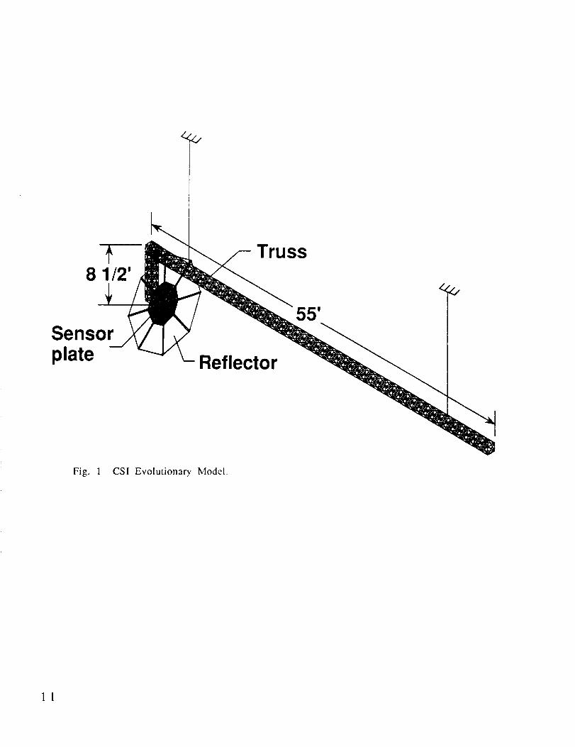
NASA Langley Research Center iscurrently planning closed-loop controlground tests on a platform-like structureconsisting of a long truss and a largereflector. Since this test article is likelyto be modified as the test programproceeds, it is referred to as theEvolutionary Model. Figure 1 shows theCSI Evolutionary Model configuration
with the reflector in place. (Thereflector analyzed and tested did not have
a sensor plate attached. This sensor platewill be added in the future.) The purposeof this paper is to describe the designing,analytical modeling, and experimentaltesting of the reflector component of thetest article. The reflector model is shown
in Figure 2. Correlation between
analytically predicted vibrationalfrequencies and experimentalvibrational frequencies is presented.With this correlation and with the
similarities between analytical andexperimental mode shapes, the finiteelement modeling technique is validated.
Configuration Changes
The design of the reflector includeddetermining its shape, size, and material.For the purposes of the CSI tests, threeimportant design criteria were imposedon the reflector: a large diameter, smalldeformations under a gravitational load,
and a low fundamental frequency. Theprimary constraint was that the reflector
have small deformations due to gravitysince it was to be ground tested. Thereflector configuration had to bechanged several times before the designcriteria were met.
The original reflector configurationwas quite flexible. It used very thin,hinged-free ribs and two sets of shapingcables. The eight long, thin, aluminumradial ribs (8 ft. x 2 in. x 1/16 in.) werehinged at the hub (a round aluminum
plate) and were spaced at 45-degreeincrements. The length and thickness ofthe ribs were sized for a rib natural
frequency of approximately 2 Hz. One setof cables between the tips of the ribscaused the ribs to buckle into a dished
shape. The second cable set providedtension and stability from behind eachrib (connecting at the 3/4 length pointon the rib), causing all of the ribs tobuckle in the same direction. Each cablein this second set attached to a rod which
passed through the hub. When erected,so that the face plane of the reflector was

perpendicular to the ground plane (theactual test position), the gravitationalforce on the ribs caused them to deformexcessively.
An iteration on this original designcalled for thicker ribs with less weight.The geometry remained the same, but 1/4in. thick, pultruded fiberglass ribsreplaced the thin aluminum ones. All ofthe ribs did not have the sameprestressedshape due to irregularities throughoutthe pultruded fiberglass material.Therefore, the material for the reflectorribs was changed back to aluminum.
A third reflector model used 1/4 in.thick aluminum ribs which were 2 in.wide. The two cable sets were used again,as in the preceding configuration. Whenplaced in the test position, the center rodshowed a large amount of deflection dueto the length of that rod and the weightof the thick aluminum ribs it had tosupport. Another change in the reflectordesign was necessary.
The next reflector configurationchanged the original designsubstantially. The center rod wasremoved as well as the set of cablesconnected to it. The ribs (aluminum, 1/4in. thick and 1 in. wide) were bolted tothe hub, instead of pinned. The tensionin the cables connecting the tips of theribs gave the reflector a slight dishshape. When erected in the test position,the ribs again sagged excessively. Thedeflections, however, were not due to thethickness, but were due to the rib width.The ribs extending from the sides of thereflector twisted near the tips becauseofa small moment of inertia about an axisrunning along the rib. This conditionindicated that the ribs needed a largerwidth.
The final design uses an aluminumrib 1/4 in. thick and 2 in. wide, see Figure3. The tension in the single set of cablesat the rib tips shape the reflector. Whenerccted into the test position, the ribsdeflect a small amount. This finalreflector meets two design criteria: smalldeflections in a gravitational field and alarge diameter, approximately 16 ft.Additionally, this design has a small static
2
torque compared with the other designs.Information on meeting the thirdcriterion, the low vibrational frequency,was provided by the experimental testsand the finite element model analyses.
Reflector Description
As described above, the reflector
configuration consists of 8 radial ribs, aset of cables and a central, round hub asshown in Figure 3. The finite elementmodel of this configuration wasgenerated. Also, this was the reflectortested in the laboratory. The 8 radial ribs
measure 93.25 in. long, 0.25 in. thick, and2 in. wide. Each of these ribs extend
radially from the center of the hub,which is a 3/8 in. thick plate with an 8 in.radius. The ribs are oriented 45 ° apartaround the hub. Each rib overlaps thehub by 5.25 in. and is bolted to the hub.Therefore, the distance from the rib end
to the hub center is 2.75 in. The overlapgives the flat reflector a diameter ofexactly 16 ft. from one rib tip to theopposite rib tip, before the cables are
tightened. The bowl-shape of thereflector is caused by circumferential,tensioning cables which hold the ribs ina prestressed shape. The set of cablesconnecting the rib tips consists of 8separate steel cables, 1/32 in. diameter.One end of a single cable attachessecurely to one rib tip. The other end ofthis cable loops around a thumb screw onthe tip of an adjacent rib. The thumbscrew winds to adjust the length of thecable, and therefore the tension. This
set-up continues around the reflector foreach of the ribs. From the dimensions
and configuration of the single rib model(refer to Single Reflector Rib -Configuration, below), the distancebetween the deformed rib tips wascalculated using the geometricrelationship in Equation 1.
Ic = 2rcosB (1)
The distance between ribs (lc = 71.75 in.)
was set by adjusting the cable length.The radius of the reflector, r, is 93.75 in.
(91 in., as in the single rib model, plus2.75 in. of the hub that is not overlapped).

The angle, B = 67.5°, is definedbetweenarib and a cable connectedto that rib. Theprestressed structure has a diameter of187.5in. (15 ft. 7.5 in.) with a depthof 18in., measured from the hub to the planepassing through the ribs tips.
Figure 3 indicates that each cablecarries 9.44 lbs. of tensile force. Thisvalue comes from the geometricrelationship in Equation 2, knowing theforce on the cable in the single rib model(refer to Single Reflector RibConfiguration).
Tr = TS/2cosB (2)The cable tension in the reflector and inthe single rib model are Tr and Tsrespectively. The factor of 1/2 isnecessary because the tension from 2cables acts on each rib in the reflector.Table 1 lists the actual tensionmeasurements taken on each of the 8cables with a tensiometer. The numberscorrespond to the cable numbers inFigure 3. The discrepanciesbetween thecalculated and the measuredvalues resultfrom differences in the gravitational loaddirection for each rib and from slightdifferences in the individual ribdimensions.
The reflector mounts via four largebolts through the hub, to the backstop inthe laboratory of building 1293B asshown in Figure 2.
Before testing the reflector for itsvibrational properties, it was necessaryto perform preliminary analyses andtests.
Single Reflector Rib
A single rib was analyzed and testedto determine its natural frequencies. Theresults provided vibrational and staticinformation applicable to the reflectormodel.
ConfigurationAs shown in Figure 4, the single rib
model closely approximates a rib in thereflector. Physically, the long strip (2 in.x 0.257 in. x 93.25 in.) of 6061-T6aluminum is bolted to an I-beam. This I-
beam was secured to the floor of the
laboratory. A hinge fastened to the freeend of the rib provided a means forattaching a cable. The cable ranperpendicularly to the I-beam and had athumb screw at that end to adjust thelength of the cable. When the cable wastightened, the rib deflected into a bowed
shape. For the test, the rib tip had adeflection of 18 in. while the cablecarried a 7.23 lb. load. In this deformed
shape, the tip of the rib was 91 in. from
the I-beam. The rib length, measuredfrom the securing bolts to the tip, is thesame in this single rib configuration asin the reflector. The rib remained in this
prestressed condition throughout thevibration tests and was modeled in thefinite element model.
Analytical Model
A finite element model (FEM)provided accurate static and vibrationaldata to confirm tests performed in thelaboratory. The Engineering Analysis
Language (EAL)t FEM contained 9elements: 1 for the cable and 8 for the
aluminum rib. The standard propertyvalues for steel and aluminum were used
for the cable and rib respectively. Therib elements were input as rectangularbeams with the correct dimensions. A rod
element was used to represent the cable.The geometry and preloads needed to
be modeled correctly in the FEM so thatthe final stiffness closely duplicates thestiffness of the test article. With the
hardware, the force caused by the wiretension deforms the rib to give a bowedshape. Since EAL is only valid for linearsystems with small deflections, theselarge deflections cannot be accuratelymodeled in the FEM by applying a cableload to the undeformed rib. Therefore, a
method for both shaping the rib andpreloading the members needed to bedeveloped for the FEM.
The shape of the rib was formedfrom the coordinates of the node points.The coordinates of each node point in theFEM, without any preload in the elements,match those of points along the stressed,

single rib model in the laboratory.Therefore, the unstressed FEM has the
same shape as the test article.The compressive preloads in the rib
elements were calculated by anindependent section of the EAL input file.In this section, a force vector was
temporarily applied at the rib tip. Theload had a magnitude of 7.23 lbs. andpointed downward, along the cable. Themagnitude and direction of this vectormatched the cable load. No other preloadsor forces were applied; this section wasrun solely to determine the loads in eachof the rib elements. The results aretabulated in Table 2. The element
numbers correspond to those in Figure 4.The results show that the elemental loads
increase along the rib from the tip to thebase.
After the elemental loads were
determined, these loads were
permanently applied as thermal loads.Knowing the forces on the elements (F),the following equation was used tocalculate the appropriate temperaturechanges (AT) to be applied across thosespecific elements.
AT = F/czEA (3)
The coefficient of thermal expansion (or)and the elasticity modulus (E) were inputwith the material properties. Since thecoefficient of thermal expansion is onlyused for the preloads, its actual value isnot used in the EAL runstream. Acalculated coefficient eases the
numerical computation. The crosssectional area (A) was calculated from theelemental dimensions.
The change in temperature appliedto preload the cable element was
calculated using Equation 3. A negativecoefficient of thermal expansion listedwith the cable material propertiesindicated that this thermal load is tensile
instead of compressive.After defining the cable and rib
preloads, they were applied in the EALprogram. Since the deformed geometrywas input, the preloads along the ribwere input separately on the ribelements. The thermal change across the
4
cable induced a preload which matchedthat in the laboratory set-up, 7.23 lbs.
The output from the first runindicated that two problems existed withthe modeling method. First, the correctthermal loads were not induced acrosseither the cable element or the ribelements because the elements were free
to move. The elements needed clamped-clamped ends for the full thermal effect.Second, the ribs deflected from the zero-
load shape. Since the nodal coordinatesalready matched the desired bowed shape,any additional deflection caused anincorrect final rib shape. Both of theseproblems were solved by applying asecond constraint case.
A second constraint case was appliedto the structure to embed the preloads inthe stiffness matrix before performing avibrational analysis. By constraining allthe degrees of freedom at every nodepoint, the rib did not deflect and thethermal changes induced the correctloads. The KG-matrix, a differentialstiffness matrix associated with the fullyconstrained and internally loadedstructure, is created after preloading thestructure. Then, the KG-matrix is added to
a general stiffness matrix (K-matrix).This K-matrix is initially created with thematerial properties, nodal geometry, andelemental dimensions. The sum of the K-
matrix and the KG-matrix forms a new K-
matrix. With the appropriate stiffnessdue to the embedded preloads, the fullyconstrained condition was removed.
Then a vibrational analysis wasperformed on the structure with thecorrect constraint case. The first 4
frequencies and the associated modeshapes are shown in Figure 5.
Testing and ResultsVibrational tests were performed on
the single reflector rib to confirm theanalytical rcsults. A hammer was used toexcite the structure, and an
accelerometer at the tip of the ribmeasured the excitations. A two-channel
Hewlett-Packard 3562A Dynamic SignalAnalyzer conditioned the data generatedby the load cell in the hammer and by the

accelerometer. A force window placed onthe excitation channel allowed the firstpart of the time record to pass whilecompletely attenuating the last part. Thistype of window is effective with impulseexcitations because the signal for theinitial impact is recorded while residualeffects are attenuated. An exponentialwindow on the response channelattenuates the signal at an exponentiallydecaying rate determined by an inputtime constant. Also, this analyzercalculated an averaged frequencyresponse function (FRF) after twentyseparate FRF's were generated. Theaveraged FRF is shown in Figure 6 withthe phase plot shown below. The sharppeaks and the 180° phase shifts at thesepeaks mark the natural frequencies ofthis structure. For comparison with theanalytical frequencies, the first 4experimental frequencies are given inFigure 5. With only one accelerometer,experimental mode shape data is notavailable.
Discussion
A high degree of correlation existsbetween the predicted and measuredfrequencies. The discrepancy in the 2ndmode frequencies results from theclamped condition at the base of the rib.The FEM perfectly models the clamp. Thetest article can not be perfectly clampedin the laboratory.
This high degree of correlation gaveconfidence that the discretization of therib was sufficient for use in the reflectorFEM. The next step included analytically
modeling and testing the reflector. Seethe Test Results and Discussion section for
correlation between the single rib resultsand the reflector results.
Reflector Analytical Model
A descriptive and accurate
analytical model is essential to predict thevibrational effects of the actual
slructure. The FEM contains analytical
approximations of each of thecomponents which comprise thereflector. Also, preloads are placed in the
FEM cables and ribs. The Appendixcontains the EAL runstream for thereflector FEM.
Common beam clcmcnts and material
properties describe the reflector model.Nine beam clcmcnts (10 nodes) compriseeach rib, the ninth clement ovcrlaps andconnects to the hub. The elements have
the properties of aluminum and measure1/4 in. thick and 2 in. wide. Sixteen plate
elements (8 triangles and 8 trapezoids) fittogether to form the hub. These elementshave a 3/8 in. thickness. The octagonally
shaped hub of the FEM weighs less thanthe actual circular hub. Lumped massesplaced at the rim of the octagonal hubreplace this weight difference. Rodelements, 1/32 in. diameter, with material
properties of steel wire describe thecables. The bolts connecting the ribs tothe hub and the hub to ground are
represented by 1/4 in. diameter steel,tubular elements. Five degrees offreedom, 3 translational and 2 rotational,were constrained to zero on the four bolts
representing connections to ground. Thethird rotational degree of freedom, aboutthe bolt axis, was left free. All of the
other nodes had six degrees of freedomfree.
The approach used for applying thepreloads in the single rib model was nowused for the reflector model. Refcr to the
Single Reflector Rib Analytical Model.Unlike the single rib model, the
reflector dynamics were affected bygravity. Therefore, the new K-matrixhad another addition when a
gravitational load was applied to thestructure. The gravitational loadsimulates the force the structure is
subject to while secured to the backstopas shown in Figure 2. Vectors point the
gravitational load in the same directionwith respect to the structure as the
gravitational vector in the laboratory.Because the gravitational force affectsthe stiffness of the structure, it is added to
the new K-matrix through a second KG-matrix. The sum of the new K-malrix and
the second KG-matrix gives a final K-matrix which is used in the vibrational
analysis. Both the thermal preloads and

the gravitational load are embedded inthe final structural stiffness. Also, the
vibrational analysis is performed on astructure with the correct constraint
case.
Analytical Results
Table 3 lists the first 11 natural
frequencies while Figure 7 shows themode shapes. Mode 1 of Figure 7 indicatesthe rib numbering scheme which will be
used in describing the mode shapes.Mode 1 exhibits a rocking motion
about the hub of the reflector involving
some bending of the ribs. Mode 2 isreferred to as the "butterfly" or "saddle"mode. In this mode, two sets of 2 ribs,
namely ribs 2 and 6 and ribs 4 and 8,vibrate 180 ° out-of-phase with respect toeach other. In mode 3, two sets of 3 ribs
vibrate completely out-of-phase, namelyribs 3, 6, and 8 and ribs 2, 4, and 7. Two
sets of 4 ribs vibrate out-of-phase in the4th mode. This symmetric mode shapeinvolves ribs 2, 4, 6, and 8 in one set; the
remaining ribs form the second set. Allthe ribs move in-phase in the 5th mode.Each rib in the first 5 modes deforms like
the first bending mode of the single ribmodel. Different coupling combinationsof this one rib shape characterize the
five separate reflector mode shapes. Seethe Test Results and Discussion section for
further discussion on the mode shapesand frequencies.
Due to the cyclic symmetry of thestructure, the first 3 modes have a pair ofeigenvalues. These pairs result from thetwo planes of symmetry in the structure,set apart by a 45 ° angle. One mode shapeof each pair differs from the other by a45 ° rotation of the structure.
Experimental test results confirmedthe method used to analytically model thisreflector.
Instrumentation and Test
Procedure
The vibrational testing wasperformed to validate the analyticalmodeling method. The reflector hungfrom the backstop in the laboratory. Astandard hammer test was performed.The transducers used were a PCB impacthammer with a load cell and three PCB
Structcel accelerometers. A soft tip onthe hammer helped excite the lowfrequencies of the reflector. A GenRad2515 Computer-Aided Test Systemprocessed all of the data from thetransducers.
Since the rib tips deflected the most,all of the transducers were placed there.The impact hammer struck a single ribtip in a single direction throughout all ofthe testing. This kept the excitation pointconstant. Eight response points (1 ateach rib tip) were necessary to describethe first 5 mode shapes. Therefore, thethree accelerometers were moved after
recording data at a response point. Threefrequency response functions wererecorded and averaged together at eachof the 8 test locations. The structure was
allowed to freely decay as themeasurements were recorded. After
conditioning and storing all of thenecessary data, the GenRad used apolyreference curve fitting program tofit the final frequency responsefunctions. From those curve fit
functions, the natural frequencies,damping values, and the relativeamplitudes were calculated. These
parameters defined the experimentalmode shapes, which were animated onthe GenRad.
Test Results and Discussion
The calculated data gave informationon the response of the experimentalmodel of the reflector. Though notshown in this paper, the mode shapesgenerated by the GenRad systemduplicate the shapes calculated by theEAL program. Table 3 compares theanalytical and experimental frequencies.The experimental results compared wellwith the analytical results.
6

Mode ShapesThe vibrational characteristics of
the reflector were described by modeshapes from both the FEM and theexperimental model. Also, the single ribmode shapes provided informationrelating to the reflector. The modeshapcs of the reflector can bc classificdinto specific groups. A group is dcfincdas a series of mode shapcs, each of which
has a single, characteristic bendingshape for any individual rib. Forexample, the first five bending modesbelong to the same group because all ofthe individual ribs, in each mode, have
the same local shape. Table 3 lists thefrequencies of the mode shapes in thefirst two groups. For the first group, thelocal rib mode shape corresponds to thefirst bending mode shape of the singlerib model. Each rib in the modes of the
second group has a shape whichcorresponds to the second bending modeshape of the single rib model, and so on.
Different relative positions of theseindividual ribs define the global modeshapes of the reflector.
Within each group, there are 5
distinct global mode shapes, see Table 3.These modes are sequentially labeled withmode numbers (m = 1, 2, 3, 4, 0), where mis the number of complete sinusoidalcycles formed around the circumferenceof the reflector at the cables. To visualize
the sinusoid produced by the cables, the3-axis displacement is plotted versus therib number. The undeformed shape isthe zero line for the 3-axis. Figure 8illustrates the procedure for determiningthe mode number. The m = 2 mode for the
first mode shape group is shown inFigure 8.
As described in the AnalyticalResults section, the first 3 mode shapes ofeach group are sets containing twosimilar mode shapes with similarfrequencies. See Table 3. These double
values result from the symmetry of thereflector. The only difference betweenthe similar mode shapes is a 45 ° rotation.The m = 4 mode shape in each group doesnot have a double value because arotation of 45 ° results in the exact same
mode shape. Also, the m = 5 modes areunique and do not have double values.
FrequenciesTable 3 shows that the 5th and 10th
bending frequencies (the frcquencics of
the m = (I mode shapes in Groups 1 and 2)match closely with the 1st and 2nd singlerib frequencies givcn in Figure 5. Thecorrelation between the m = 0 globalmode and the single rib frequencies isexpected. The ribs in the m = 0 mode areall in phase and all deflecting to themaximum amount for the group. This m =0 configuration creates the most energyand, hcnce, the highest frequency forany mode shape in the group.
However, the frequencies for the m= 1 to m = 4 global modes are lower thanthe frequency of the m = 0 mode. Thefrequencies of these modes aredetermined by the number of ribsvibrating out-of-phase. In the m = 4mode, adjaccnt ribs arc out-of-phase.This shape, with four ribs in phase andfour ribs out-of-phase, contains a largeamount of energy. Therefore, the m = 4frequency is higher than the m = 3frequency, which has only 3 ribs 180 °out-of-phase wilh 3 other ribs. A similarexplanation can be used for the m = 2 andthe m = 1 frequencies.
In summary, the ribs vibrate to themaximum displacements in the m = 0modes. This condition has the most
energy for the entire group. From the m= 1 to m = 4 modes, the energy andfrequencies increase in relation to thenumber of ribs vibrating out-of-phase.
Concluding Remarks
In this paper, the design, analysis,and vibrational test of a 16-foot radial ribreflector model have been described. The
characteristic mode shapes andfrequencies have been documented. Theanalytical predictions, based on the FEM,correlated well with test results for the
first fivc reflcctor modes. The closelymatched frequencies and similar modeshapes of the analysis and test confirmedthe analytical modeling method.

The author would like to extend histhanks to Dr. Garnett Horner for hisguidance and support through thisproject. Also, Harold Edighoffer, JimBailey, and Paul McGowan deservethanksfor their help.
Reference
I 1 ] Whetstone, W. D., EISI-EAL
Engineering Language ReferenceManual, Engineering InformationSystems, Inc., San Jose, 1983.

Table 1. MeasuredCableTcnsion. Refer to Fig. 3
Cable number Tension (lb.)
1 9.83
2 9.42
3 9.86
4 10.74
5 8.65
6 9.98
7 10.19
8 8.91
Table 2. Analytical rib element loads. Refcr to Fig. 4
Rib Element Prestress Force (lb.)
1 6.87
2 6.94
3 6.97
4 7.04
5 7.09
6 7.16
7 7.20
8 7.22
9

Table 3. Analytical and Expcrimental Frequencies with mode type and number
Mode (type)
1 (bending)
2 (bending)
3 (bending)
4 (bending)
5 (bending)
6 (bending)
7 (bending)
8 (bending)
9 (torsion)
10 (bending}
11 (bending}
Mode Number
1
2
3
4
0
2
3
i
4
0
Analytical Freq.
(Hz.)
1.55
1.55
1.63
1.64
1.95
1.98
2.13
3.05
5.73
5.75
5.83
5.84
5.96
5.98
6.06
6.12
13.70
Experimental
(Hz.)1.51
Freq.
1.64
1.97
2.13
2.76
Group 1
Group 2
10
z,Z,,
8 1/2'
Sensorplate
Truss
Reflector
Fig. 1 CSI Evolutionary. Model.
11

(a) Front view.
(b) Side view.
Fig. 2 Photographs of the 16-foot radial rib reflector model.
ONIG_N/_,L PA_E 12

Hubt = 3/8"
Reflector
Radius 7' 9 314"
7 ble 1
8, Rib 1 __\\'_ Rib
//5'11 2"
6 Hub _ Cabl 6 _ ;
..... Tensio :
5 43
(a). Fron! view wilh rib and cable
numbers for identification.
Ribt= 1/4"
(b). Side view.
13 Fig. 3 Reflector lest model with componcl_l dirncnsiorls.

I
Fig. 4
T=7.23 Ibs
91"
Cable ---_
ThumbScrew
2
3
4/_Rib
_--18'_l_f,'---'B race _l-bea mI
Side view of single rib model with dimensions and clcmcnl numbers.
Mode
1
2
3
4
Analytical
Freq. (Hz.)
2.88
13.56
21.28
34.71
Experimental
Freq. (Hz.)
2.9
13.05
21.3
36.55
Cabl
L
'/
Rib
l
o
Mode 1 Mode 2 Mode 3 Mode 4
Fig. 5 Single rib frequency comparison with analytical mode shapes.
14

60.01
Magnitude(dB)
i ] T r ,I I i I
_,_ , ,, , I ,_-J\ /\
180
Phase(degrees)
-180!
iI
0 4 8 12 16 20 24 28 32 36 40
Frequency (Hz)
Fig. 6 Magnitude and phase plots of an averagedfrequency response function from a single rib test.
15

]
Mode 1
1.55 Hz.
Mode 2
1.64 Hz.
!
Mode 3
1.98 Hz.
Mode 4
2.13 Hz.
Fig. 7 Mode shapes and analytical frcqucncics of thc rcf]cclor.
16

Mode 5
3.05 Hz.Mode 6
5.75 Hz.
Mode 7
5.83 Hz.
Mode 8
5.96 Hz.
Fig. 7 Continucd.
17

Mode 9
6.06 Hz.Mode 106.12 Hz.
Torsional
Fig. 7 Continued,
Mode 11
13.70 Hz.
18

Rib
Number
3-Axis
Dis )lacement
1234 5678
Mode 2
m=2
Fig. 8 Mode number determination method - rib number plolted vs. 3-axis displaccment.
19

Appendix
This is a copy of the EAL run stream used to analytically model the 16-footmodel.
S __
S --
S --
S --
S --
*CALL(18 PLB JCL)
*XQT U 1
*(GEOM)
*XQT TABSSTART 97
*ONLINE=I
S*ECHO=I
THIS EAL INPUT STREAM MODELS THE 16-FOOT RADIAL RIB
REFLECTOR DEVELOPMENTAL MODEL. CABLE DENSITY
AND LUMPED MASS MATRIX ARE CHANGES FROM THE ORIGINAL
RUNS. THE DEFORMED RIBS ARE IN THE ZERO LOAD SHAPE.
THE PRELOADS MUST BE ADDED AFTER THE GEOMETRY IS
INPUT. REFER TO THE COMMENTS TO UNDERSTAND THE INPUT
END
$ -- USE EITHER ONLINE OR ECHO
TITLE' ALUMINUM REFLECTOR WITH EIGHT RIBS, 16 FEET DIAMETERTEXT
'l RIB SIZE 2X1/4 INCHES'2 FLN = FORTM1
MATC$
1 10.E+06 0.333 0.098 2.0E-08 $ ALUMINUM RIBS AND PLATE
$ -- ALUMINUM COEFF. OF THERM EXPANSION SET FOR NUMERIC
$ -- CONVENIENCE WHEN APPLYING PRELOADS TO RIB ELEMENTS
2 30.E+06 0.3 0.283 $STEEL BOLTS THROUGH PLATE AND RIBS
3 30.0E+06 .3 0.177 -4.1047E-06 $ STEEL CABLES THE COEFF. OF THERMAL EXPANSION FOR STEEL CABLE IS CALCULATED TO
$ INDUCE LOAD WHEN SUBJECTED TO 100 DEG. TEMP CHANGEJLOC$
*FORMAT=2
$ -- GEOMETRY OF DEFORMED REFLECTOR
$ -- CENTER OF COOR. SYS IS AT PLATE CENTER, HALF-THICKNESS OF A RIB1 93.7500 0. 18.1250 93.7500 315.0 18.1250 8 12
2 82.3125 0. 14.3750 82.3125 315.0 14.3750 8 12
3 70.8125 0. 11.0000 70.8125 315.0 11.0000 8 12
4 59.2500 0. 7.8125 59.2500 315.0 7.8125 8 12
5 47.6250 0. 5.1250 47.6250 315.0 5.1250 8 12
6 35.8750 0. 2.7500 35.8750 315.0 2.7500 8 12
7 23.9375 0. 1.0625 23.9375 315.0 1.0625 8 12
8 16.1250 0. 0.3125 16.1250 315.0 0.3125 8 12
9 7.7500 0. 0.0000 7.7500 315.0 0.0000 8 1210 3.7500 0. 0.0000 3.7500 315.0 0.0000 8 12
11 7.7500 0. -0.3125 7.7500 315.0 -0.3125 8 12
12 3.7500 0. -0.3125 3.7500 315.0 -0.3125 8 12
97 0.0000 0.0000 -0.3750
radial rib reflector
20

$DESCRIBE THE COMPONENT GEOMETRY
BA$
RECT 1 2.0 0.250 $ -- REFLECTOR RIBS, EXACTLY .25 X 2 IN.
TUBE 2 0.0 0.125 $ 1/4 INCH BOLTSBC
1 .000767 $ --- 1/32 DIAMETER CABLE
SA
NMAT=I
FORMAT=ISOTROPIC
1 .375 $ -- PLATE THICKNESS IS 3/8 IN.MREF$
123 1 0.
212 1 1.0
CON=I $ -- ORIGINAL CONSTRAINT CASE
ZERO 1 2 3 4 5 $ --- PLATE CLAMPED (CONSTRAINED)TO BACKSTOP
$ -- AT 4 BOLTS, EACH WITH 5 DOF'S24:48:72:96 $ --- FOR ONE ROTATIONAL DOF
CON=2 $ -- ADDITIONAL CONSTRAINT CASE
ZERO 1 2 3 4 5 6 $CONSTRAIN EVERYTHING TO APPLY LOADS IN K1 STIFF. MATRIX
1,97,1RMASS
REPEAT 8,12
11 .000371 $ POINT MASSES ADDED BECAUSE HUB IS MODELED AS
$ -- AN OCTAGON WHICH HAS SMALLER VOLUME THAN ACTUAL CIRCULAR PLATE
*XQT ELDE235
GROUP 1' OUTER RIM CABLES
NMAT=3
NSEC=I
1131710
85 1
E215
GROUP 1' RADIAL RIBS
NMAT=I $ --- 2 X .25 INCH ALUMINUM STRIPSNSEC=I
1219812
GROUP 2' BOLTS THROUGH HUB
NMAT=2NREF=2
NSECT=2
9 11 1 1 8 1210 12 1 1 8 12
E335
GROUP 1' INNER TRIANGLES OF ANTENNA tlUBNMAT=I
$ --- ALWAYS ALIGN ONE SIDE WITH COORDINATE AXIS97 12 24
97 36 24
97 36 48
97 60 48
97 60 72
97 84 72
97 84 96
21

97 96 12
E435
GROUP I'OUTER QUADS OF ANTENNA HUBNMAT=I
$ --- ALWAYS ALIGN ONE SIDE WITH COORDINATE AXIS
12 11 23 24
36 35 23 24
36 35 47 48
60 59 47 48
60 59 71 72
84 83 71 72
84 83 95 96
12 11 95 96
*XQT E$RESET G=386.0
*XQT EKS
*XQT TAN
*XQT K $ -- ORIGINAL STIFFNESS MATRIX K-MATRIX CREATEDRESET KFAC=0
*XQT RSIRESET CON=2
*XQT MRESET G=386.0
*END
*(TMAS) END
*XQT AUS
M1 = SUM(DEM,RMAS) $ IF WANT CONSISTENT MASS MATRIX INSTEAD OF LUMPED
!MNAME=M1 $ MASS MATRIX, USE CEM, NOT DEM IN ABOVE LINE
*PERFORM(28 TMCG)*RETURN
*END
*(SYSV) END$ -- THIS IS THE INDEPENDENT SECTION WHICH IS RUN BY ITSELF TO
$ -- DETERMINE THE PRELOADS IN THE INDIVIDUAL RIB$ -- ELEMENTS ONLY
*XQT AUSALPHA: CASE TITLE: 1' APPLY CABLE LOADSSYSVEC: APPL FORC 1
I=1: J= 1:-7.23
S ._
1=1 : J=49: 7.23
!=2: J=25: -7.23
1=2: J=73: 7.23
I=1: J=13: -5.11
I=2: J=13: -5.11
I=I: J=37: 5.11
I=2: J=37: -5.11
I=1: J=61: 5.11
1=2: J=61: 5.11
I=1: J=85: -5.11
I=2: J=85: 5.11
*XQT SSOL
*XQT VPRT
$ - VECTOR FORCE COMPONENTS OF CABLES APPLIED AT
RIB TIPS
22

LINE=24
JOINT=l,12:49,60:1 3,24:61,72:25,q6:73,84:37,48:85,96TPRINT STAT DISP 1 1
*XQT ES
MAXPAGE=48
U = STAT DISP 1 1E23
SE21 = PX,PY,PZ, MX,MY,MZE21
E33
E43
*XQT DCUTOC 1
*END
*(ELDA)$$
*XQT AUS
ALPHA: CASE TITLE: 1' APPLY CABLE PRELOADS, 89/03/28ELDATA: TEMP E23 1CASE 1
G=I: E=l,8: 100.0, 0., 0. $ -- THERMAL CHANGES OVER CABI.ESELDATA: TEMP E21 1
END S -PRELOAD APPLICATION SECTION
COMPUTE PRELOAD
ALPHA A = F/(DT * E * A)
-- THERMAL CHANGES OVER RIB ELEMENTS
CASE 1
G=I: E=1,64,9: 68.702, 0.0, 0.0
G=I: E=2,65,9: 69.374, 0.0, 0.0
G=I: E=3,66,9: 69.700, 0.0, 0.0 $
G=I: E=4,67,9: 70.442, 0.0, 0.0
G=I: E=5,68,9: 70.867, 0.0, 0.0
G=I: E=6,69,9: 71.588, 0.0, 0.0
G=I: E=7,70,9: 71.969, 0.0, 0.0G=I: E=8,71,9: 72.250, 0.0, 0.0
*XQT EQNF
*XQT SSOL
RESET CON=2, SET=I $ CONSTRAINT CASE 2 IS CALLED
$ ALL POINTS FULLY CONSTRAINED
*XQT GSF
RESET EMBED=l, CON=2*XQT PSF
RESET DISPLAY=2E23:E21
*XQT KG
*XQT AUS
KI=SUM(K,KG) $ -- NEW STIFFNESS MATRIX CREATED: SUM OF ORIGINAL
$ K-MATRIX AND DIFFERENTIAL STIFFNESS OF PRELOADS ADDED*END
*(GRAV) END
*XQT RSIRESET CON=I K=KI
*XQT AUS
ALPHA: CASE TITLE: 1' APPLY GRAVTITATIONAL LOAD, 89/03/17
RBM = RIGID (0.0, 0.0, 5.47) SRIGID BODY MASS: APPLIED AT MASS CENTERDEFINE XI = RBM AUS 1 1 1
23

DEFINE X2 = RBM AUS 1 1 2
VEC = SUM(.924 X1, .383 X2) $ NEED TO ORIENT GRAV VECTOR CORRECTLY
APPL FORC 2 = PROD(-386.1 M1, VEC)
*XQT EQNFRESET SET=2
*XQT SSOLRESET K=K 1
RESET CON=l, SET=2
*XQT GSF
RESET EMBED=l, CON=l, SET=2
*XQT KG $ -- GRAV. DIFFERNTIAL STIFFNESS MATRIX FORMATION
*XQT AUSKTOT=SUM(KG,K1) $ ADDING GRAV DIFFERENTIAL STIFF. MATRIX, KG,
$ TO NEW STIFFNESS MATRIX K1 TO COME UP WITH FINAL K-MATRIX, KTOT
*XQT VPRT
PRINT EQNFPRINT STAT DISP $ THESE LINES PRINT OUT REATIONS AND DISPLACEMENTS
PRINT STAT REAC
*END
*(VIBR) END $EIGENVALUE SOLUTION
*XQT E4RESET M=M1 K=KTOT CON=I
RESET NMODES = 17
*XQT DCUTOC 1
*XQT VPRTTPRINT VIBR MODE $ TO GET THE EIGENVECTORS
* END
*(PLTU) END $ PLOTTING COMMANDS*ECHO= 1
*FREE 18
*XQT PLTASPEC 1
STITLE'4 PTS. ON PLATE ARE TOTALLY CONSTRAINED
S2TITL'16 FOOT DIAM REFLECTOR, W/GRAVITY
VIEW 3
ROTATE 67,3 60,1 23,2
AXES 0., 0., 90, 10., 10., 10.ALL
SPEC 2
STITLE'4 PTS. ON PLATE ARE TOTALLY CONSTRAINED
S2TITL' 16 FT DIAM REFL, BARS 2XI/4
VIEW 1,-3,2,1
LROTATE 67,3 180,1
AXES -75., 80., -25., 20., 20., 20.ALL
*XQT PLTBDISPLAY=VIBR
INLIB=I
CASES 1,17 $MAKE SURE THIS IS SET TO THE APPROPRIATE NUMBER OF CASESDNOR M= 15.0
OPTION 26,27
PLOT 1 ,2
24

*END
*DCALL(GEOM)
*DCALL(TMAS)
$*DCALL(SYSV)$
*DCALL(ELDA)
*DCALL(GRAV)
$ GEOMETRY CARD CALLED
$ MASS MATRIX FORMED
$ THIS-SECTION IS USED BY ITSELF, ONLY TO SOLVE FORINDIVIDUAL RIB ELEMENTAL LOADS
$ PRELOADS APPLIED WITH THERMAL CHANGES (FULL CONSTRAINT)
$ GRAV. LOAD APPLIED (CORRECT CONSTRAINT CASE)*DCALL(VIBR) $ VIBRATIONAL ANALYSIS TO GET EIGENVALUES AND EIGENVECTORS*DCALL(PLTU) $ PLOT CARD
*XQT EXIT
25

Report Documentation Page,5_ace _r_ol
I. Report No.
NASA TM-101648
4. Title and Subtitle
2. Government Accession No. 3. Recipient's Catalog No.
5. Report Date
Analysis and Test of a 16-Foot RadialRib Reflector Developmental Model
7. Author(s)
Shawn A. Birchenough
9. Performing Organization Name and Address
NASA Langley Research CenterHampton, VA 23665-5225
12. Sponsoring Agency Name and Address
National Aeronautics and Space Administration
Washington, De 20546-0001
August 1989
6. Performing Organization Code
8, Performing Organization Report No.
10. Work Unit No.
585-01-61-01
11. Contract or Grant No.
13. Type of Report and Period Covered
Technical Memorandum
1_4_ Sponsoring Agency Code ......
15. Supplementary Notes
Shawn A. Birchenough is a student at the Massachusetts Institute of Technology. This workwas accomplished during an engineering cooperative education work assignment at the LangleyResearch Center.
16. Abstract
Analytical and experimental modal tests have been performed to determine the vibra-tional characteristics of a 16-foot diameter radial fib reflector model. Single rib analyses andexperimental tests provided preliminary information relating to the reflector. A finite elementmodel predicted mode shapes and frequencies of the reflector. The analyses correlated wellwith the experimental tests, verifying the modeling method used. The results indicate that five
related, characteristic mode shapes form a group. The frequencies of the modes are determinedby the relative phase of the radial ribs.
17. Key Words (Suggested by Author(s))
Antennae modelRadial rib
Finite element analysisGround vibration tests
18. Distribution Statement
Unclassified - Unlimited
Subject Category 39
19. Security Classif. (of thiz report)
Unclassified
NASA FORM 1121 OCT 86
20. Security Chlsaif.(of this page)
Unclassified21. No. of pages
2622. Price
A03