analysis and design of moment resisting midwall
TRANSCRIPT


________________________________________________________________________ The Steel Network, Inc. www.steelnetwork.com 888-474-4876
First Published January 2010, Updated May 2017
ANALYSIS AND DESIGN OF MOMENT RESISTING MIDWALL™ BY THE STEEL NETWORK, INC.
Paul Lackey, P.E., Muhammad Ghoraba, Nabil A. Rahman, Ph.D., P.E.
and Kurtis Kennedy MidWall™ is a hold-down product intended to simplify and optimize the design and construction of a short wall or half wall in residential and commercial cold formed steel framing. Available in widths of 2 ½”, 3 ⅝” and 6”, and lengths of 24” or 48”, MidWall™ is a one piece connection/framing unit which offers optimization of material and streamlines installation. The assembly consists of MidWall™ members spaced along the length of the wall with a top track spanning between MidWall™ members. The top track acts as a load distribution member capable of distributing localized loads to multiple MidWall™ members as shown in Figure 1. A MidWall™ may be used as a cost effective solution to several common construction conditions including interior half walls, strip window framing, and parapet framing. The information provided within this technical note is intended to describe the design criteria regulated by the building code for several MidWall™ uses and give a summary of the analysis and design procedure to these criteria. This analysis procedure is also implemented in the SteelSmart® System cold formed steel analysis and design software (SSS Version 7).
Figure 1: MidWall™ Assembly
MidWall Bracket
Bottom Track
Top TrackStructural Member
Floor or FoundationSlab
Typical Wall Stud
End of Wall RequiresAdjacent MidWallSupports

________________________________________________________________________ The Steel Network, Inc. www.steelnetwork.com 888-474-4876
First Published January 2010, Updated May 2017
FULL SCALE TESTS The strength and behavior of the MidWall™ framing component were determined through a series of full scale tests performed on both the 24” and the 48” long sections for each MidWall™ member width. Tests were performed on single sections, with a concentrated out of plane point load applied 48” above the floor attachment. A 1 ⅝” flange, 54 mil (16 gauge) stud was used in conjunction with the 24” long MidWall™ member. Applied load and corresponding out of plane displacement were recorded throughout the tests. Figure 2 shows a sample load displacement curve for the 6” wide, 48” long MidWall™ product. Safety factors for allowable loads were calculated per Section F1 of the 2012 American Iron and Steel Institute (AISI S100-12) specification. Table 1 provides the maximum allowable load for each MidWall™ width. For detailed information on test setup, procedure, and results, refer to the respective MidWall™ test report by The Steel Network, Inc.
6" MidWall 600MW-48, Load @48" vs Delta F2
0
0.5
1
1.5
0 0.5 1 1.5 2 2.5Delta F2 (inches)
Load
@48
" (k
ips)
Test #1 Test #2 Test #3 .160 tag .266 Tag
Figure 2: Load Displacement Curve for 6” MidWall™ 48”
Table 1: MidWall™ Allowable Loads
Wall Width (in.) MidWall™ Member
Maximum Allowable Load @
48” (ASD), lbs
Maximum Base Moment, lbs-in.
2-1/2 250MW 128 6,150 3-5/8 362MW 332 15,940
6 600MW 407 19,540 The testing of the MidWall™ members yielded deflections higher than those calculated from structural mechanics of cantilever beams due to rotation occurring in the connection of the MidWall™ to the support structure. An analytical method has been used to determine the magnitude of the deflection caused by the base rotation by subtracting the
________________________________________________________________________ The Steel Network, Inc. www.steelnetwork.com 888-474-4876
First Published January 2010, Updated May 2017
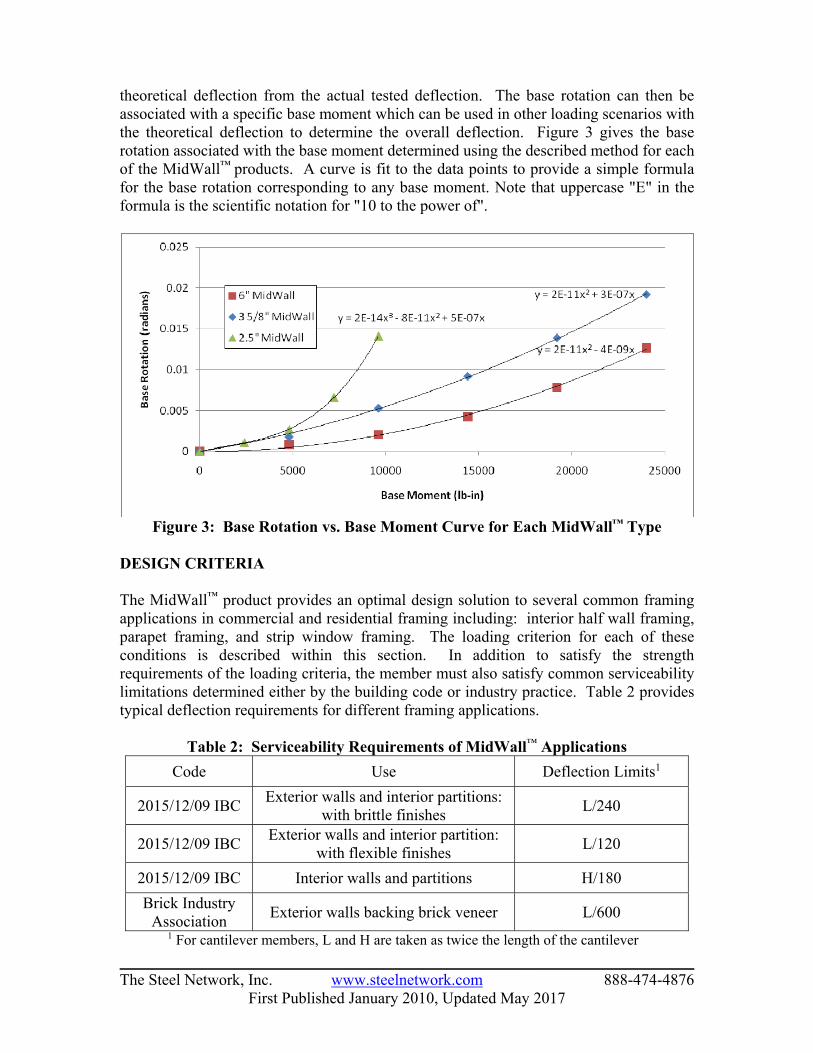
theoretical deflection from the actual tested deflection. The base rotation can then be associated with a specific base moment which can be used in other loading scenarios with the theoretical deflection to determine the overall deflection. Figure 3 gives the base rotation associated with the base moment determined using the described method for each of the MidWall™ products. A curve is fit to the data points to provide a simple formula for the base rotation corresponding to any base moment. Note that uppercase "E" in the formula is the scientific notation for "10 to the power of".
Figure 3: Base Rotation vs. Base Moment Curve for Each MidWall™ Type
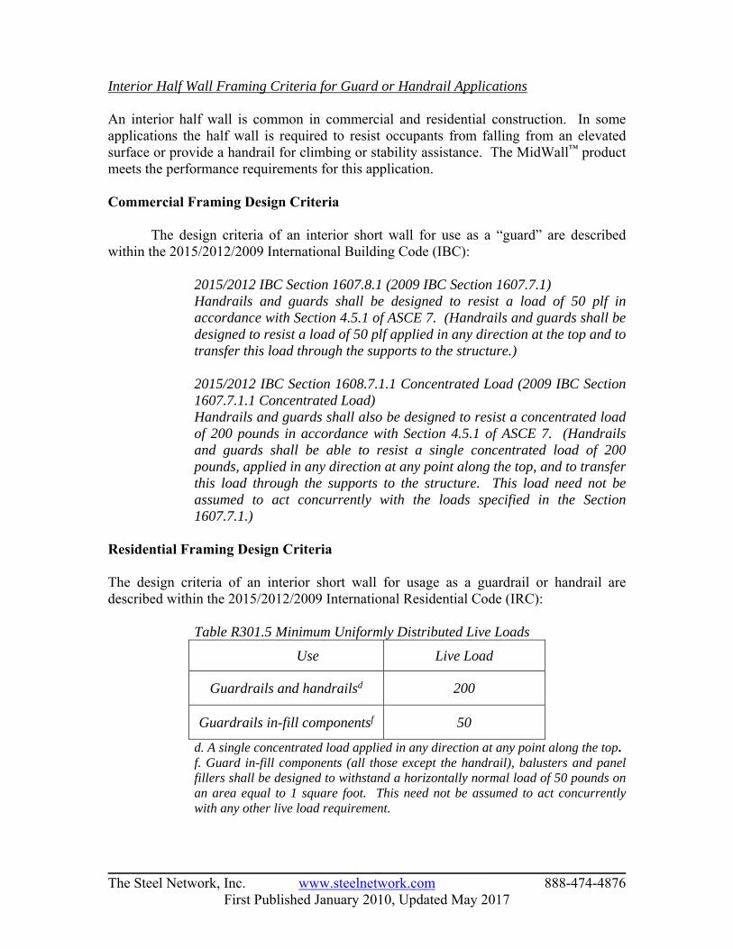
DESIGN CRITERIA The MidWall™ product provides an optimal design solution to several common framing applications in commercial and residential framing including: interior half wall framing, parapet framing, and strip window framing. The loading criterion for each of these conditions is described within this section. In addition to satisfy the strength requirements of the loading criteria, the member must also satisfy common serviceability limitations determined either by the building code or industry practice. Table 2 provides typical deflection requirements for different framing applications.
Table 2: Serviceability Requirements of MidWall™ Applications Code Use Deflection Limits1
2015/12/09 IBC Exterior walls and interior partitions: with brittle finishes L/240
2015/12/09 IBC Exterior walls and interior partition: with flexible finishes L/120
2015/12/09 IBC Interior walls and partitions H/180 Brick Industry
Association Exterior walls backing brick veneer L/600
1 For cantilever members, L and H are taken as twice the length of the cantilever
________________________________________________________________________ The Steel Network, Inc. www.steelnetwork.com 888-474-4876
First Published January 2010, Updated May 2017
Interior Half Wall Framing Criteria for Guard or Handrail Applications An interior half wall is common in commercial and residential construction. In some applications the half wall is required to resist occupants from falling from an elevated surface or provide a handrail for climbing or stability assistance. The MidWall™ product meets the performance requirements for this application. Commercial Framing Design Criteria
The design criteria of an interior short wall for use as a “guard” are described within the 2015/2012/2009 International Building Code (IBC):
2015/2012 IBC Section 1607.8.1 (2009 IBC Section 1607.7.1) Handrails and guards shall be designed to resist a load of 50 plf in accordance with Section 4.5.1 of ASCE 7. (Handrails and guards shall be designed to resist a load of 50 plf applied in any direction at the top and to transfer this load through the supports to the structure.) 2015/2012 IBC Section 1608.7.1.1 Concentrated Load (2009 IBC Section 1607.7.1.1 Concentrated Load) Handrails and guards shall also be designed to resist a concentrated load of 200 pounds in accordance with Section 4.5.1 of ASCE 7. (Handrails and guards shall be able to resist a single concentrated load of 200 pounds, applied in any direction at any point along the top, and to transfer this load through the supports to the structure. This load need not be assumed to act concurrently with the loads specified in the Section 1607.7.1.)
Residential Framing Design Criteria The design criteria of an interior short wall for usage as a guardrail or handrail are described within the 2015/2012/2009 International Residential Code (IRC):
Table R301.5 Minimum Uniformly Distributed Live Loads
Use Live Load
Guardrails and handrailsd 200
Guardrails in-fill componentsf 50
d. A single concentrated load applied in any direction at any point along the top. f. Guard in-fill components (all those except the handrail), balusters and panel
fillers shall be designed to withstand a horizontally normal load of 50 pounds on an area equal to 1 square foot. This need not be assumed to act concurrently with any other live load requirement.

________________________________________________________________________ The Steel Network, Inc. www.steelnetwork.com 888-474-4876
First Published January 2010, Updated May 2017
Interior Half Wall Framing for Walls greater than 6 feet in height The design criterion for tall interior cantilever wall framing is not explicitly defined in the IBC, but these walls exist in both commercial and residential construction in various applications. For this type of framing, a combination of design criteria for guards and interior walls greater than 6’ in height can be used. The criterion for use as a guard or handrail, as described in the previous section, is considered at a 48” height. Commercial Framing Design Criteria The design criterion for interior walls and partitions greater than 6’ in height is described within the 2015/2012/2009 IBC:
2015/2012 IBC Section 1607.14 (2009 IBC Section 1607.7.13) Interior walls and partitions that exceed 6 feet in height, including their finish materials, shall have adequate strength to resist the loads to which they are subjected but not less than a horizontal load of 5 psf.
Parapet Framing A parapet extends above the roof level for aesthetic purposes and provides a cover to hide utilities which may be present on the roof of a commercial building. In many framing applications a parapet must cantilever out from the roof level as opposed to bypassing the roof level. The MidWall™ product is capable of satisfying the load requirements for this application. Commercial Framing Design Criteria The loading criteria for a parapet is determined using the appropriate zone combinations of the component and cladding wind load as determined by Chapter 16 of the 2015/2012/2009IBC. Additionally, snow drift or ‘guard’ load requirements should be considered as applicable. Zone combinations for the component and cladding wind loads to be used on the parapet are described in ASCE 7-10 and 7-05:
ASCE 7-10 Section 30.9 (ASCE 7-05 Section 6.5.12.4.4) Two load cases, see Fig. 30.9-1, shall be considered: Load Case A: Windward Parapet shall consist of applying the applicable positive wall pressure from Fig.30.4-1 or Fig.30.6-1 to the windward surface of the parapet while applying the applicable negative edge or corner zone roof pressure from Figs. 30.4-2 through 30.4-7, 27.4-3 footnote 4, or 30.6-1 as applicable to the leeward surface of the parapet. Load Case B: Leeward Parapet shall consist of applying the applicable positive wall pressure from Fig. 30.4-1 or Fig. 30.6-1 to the windward surface of the parapet, and applying the applicable negative wall pressure from Fig. 30.4-1 or Fig. 30.6-1 as applicable to the leeward surface. Edge and corner zones shall be arranged as shown in the applicable figures. (GCp) shall be determined for appropriate roof angle and effective wind area from

________________________________________________________________________ The Steel Network, Inc. www.steelnetwork.com 888-474-4876
First Published January 2010, Updated May 2017
applicable figures. If internal pressure is present, both load cases should be evaluated under positive and negative internal pressure. (Two load cases shall be considered. Load Case A shall consist of applying the applicable positive wall pressure from Fig. 6-11A or Fig. 6-17 to the front surface of the parapet while applying the applicable negative edge or corner zone roof pressure from Figs. 6-11 through 6-17 to the back surface. Load Case B shall consist of applying the applicable positive wall pressure from Fig. 6-11A or Fig. 6-1 to the back of parapet surface, and applying the applicable negative wall pressure from Fig. 6-11A or Fig. 6-17 to the front surface. Edge and corner zones shall be arranged as shown in Figs. 6-11 through 6-17. GCp shall be determined for appropriate roof angle and effective wind area from Figs. 6-11 through 6-17. If internal pressure is present, both load cases should be evaluated under positive and negative internal pressure.)
Strip Window Framing A strip window is a window with a high width to height ratio and one that requires intermediate support of the header and sill between jamb members. In this application, a MidWall™ may be used at intermediate points along the length of the window to support the header and sill as shown in Figure 4.
Header
Sill
MidWall
Jamb
Cripple StudsDistribution of Load to Header/Sill and Jambs
Figure 4: MidWall™ in Strip Window Application

________________________________________________________________________ The Steel Network, Inc. www.steelnetwork.com 888-474-4876
First Published January 2010, Updated May 2017
Commercial Framing Design Criteria The loading criteria for a strip window is determined using the wind load determination procedures outlined in Section 1609 of the 2015/2012/2009 IBC in conjunction with ASCE 7-10 or 7-05. Residential Framing Design Criteria The loading criteria for a strip window is determined using the appropriate zone of the component and cladding wind pressure along with the exposure adjustment factor as determined by Tables R301.2(2) and R301.2(3) of the 2015/2012/2009 IRC. ANALYSIS PROCEDURE Analysis and design of the MidWall™ product for the intended application is completed using a multi-step process consisting of 3-D frame analysis, member strength and serviceability checks, and anchorage design. To determine the distribution of localized loads to multiple MidWall™ members, a 3-D frame analysis is required. The model for analysis consists of MidWall™ members fixed at the base and spaced at intervals within the wall, with a top track spanning between members as illustrated in Figure 5. Appropriate material and section properties are assigned to each framing member. A summary of MidWall™ properties can be found in Table 3. MidWall™ members are considered as prismatic and assigned the properties of the MidWall™ member, ignoring the contribution of any attached stud sections. The formation of the stiffness matrix with respect to the MidWall™ member consists of the theoretical stiffness only. The loading criteria required by the building code are applied to the model to determine the loading and reactions at each MidWall™.
Figure 5: Illustration of Assembly Model
MidWall™
Top Track
Fixed Base

________________________________________________________________________ The Steel Network, Inc. www.steelnetwork.com 888-474-4876
First Published January 2010, Updated May 2017
Table 3: Material and Section Properties
Section Properties (E = 29,500 ksi)
250MW Ix = 0.757 in.4 362MW Ix = 1.948 in.4 600MW Ix = 5.271 in.4
The strength of the member can be determined as adequate provided that the actual base moment is less than the allowable base moment given in Table 1. To determine the deflection at the end of the MidWall™ member, the theoretical deflection obtained from the frame analysis is added to the deflection contributed by the base rotation. The base rotation is determined using the base moment with the appropriate formula from Figure 3. The base rotation can then be used with the length of the member to determine the end deflection contribution from base rotation. MIDWALL™ ANCHORAGE Anchorage Design The MidWall™ anchorage functions as a fixed connection with both shear force and bending moment acting on the connection. A 2 ½” wide MidWall™ accommodates a single ½” anchor. Both the 3 ⅝” and 6” wide MidWall™ accommodate (2) ⅜” anchors. To resolve the moment, one of the anchors into the supporting structure will be in tension. The tension load in the anchor can be determined assuming the bearing stress distribution shown in the Figure 6. This assumed stress distribution provides a conservative anchor force approximation.
Figure 6: Stress Distribution on MidWall™ Connection to Foundation
T C
L ee
B
2/3 (L+e)
M
T
V
b
b V

________________________________________________________________________ The Steel Network, Inc. www.steelnetwork.com 888-474-4876
First Published January 2010, Updated May 2017
B = bearing width, in. C = compressive force on concrete, kips
e = edge distance of bolt, in. N = number of bolts in the connection L = distance between bolts, in. (= 0 in case of one bolt)
M = applied moment on connection, kips-in. T = applied tension force on connection, kips V = applied shear force on connection, kips Tb = actual tensile force on one bolt, kips
= NT
eL
M
)(32
Vb = actual shear force on one bolt, kips
= NV
Tall = allowable tensile strength of the bolt from manufacturer’s tables, kips Vall = allowable shear strength of the bolt from manufacturer’s tables, kips Check the anchorage of the MidWall™ connection as follows: Tb Tall
Vb Vall
(Tb/ Tall)5/3 + (Vb/Vall)5/3 1 (ACI 318-11, Appendix D.7) Allowable shear capacity for double anchors should consider a reduction in shear capacity relative to spacing between anchors as suggested by the anchors’ manufacturer. Tension capacity of the anchorage is not required to be reduced since only one anchor is assumed to be in tension at any given time. Both shear and tension capacities should consider reduction relative to edge distance of foundation or slab if this condition exists. Tables 4 and 5 present a non-inclusive list of anchorage options for a variety of tension loads associated with both ⅜” and ½” anchors, respectively. The tables assume a maximum shear load on a single anchor of 100 lbs for the load interaction check.

________________________________________________________________________ The Steel Network, Inc. www.steelnetwork.com 888-474-4876
First Published January 2010, Updated May 2017
Table 4: 362/600 MidWall™ ⅜” Anchor Options Max Applied
Tension on One Anchor (lbs)
Anchor Options (4,000 psi min. NW concrete strength)
1,800 ⅜” Wedge-Bolt+, 3” Embed. (Powers) ⅜” Carbon Steel Kwik Bolt 3 Expansion Anchor, 2 ⅜” Embedment (Hilti)
2,200 ⅜” Wedge-Bolt+, 3 ½” Embed. (Powers)
⅜” HAS-E Standard (ISO 898 Class 5.8) Threaded Rod set in HIT-HY 200 Epoxy, 2 ⅜” Embedment (Hilti)
2,400 ⅜” HAS-E Standard (ISO 898 Class 5.8) Threaded Rod set in HIT-HY 200 Epoxy, 3 ⅜” Embedment (Hilti)
3,200 ⅜” HAS-R SS (AISI 304/316 SS) Threaded Rod set in HIT-HY 200 Epoxy, 3 ⅜” Embedment (Hilti)
Table 5: 250 MidWall™ ½” Anchor Options
Max Applied Tension on One
Anchor (lbs)
Anchor Options (4,000 psi min. NW concrete strength)
900 ½” Wedge-Bolt+, 2” Embed. (Powers)
½” Carbon Steel Kwik HUS (KH) Screw Anchor Mechanical, 2 ¼” Embedment (Hilti)
1,200
½” Wedge-Bolt+, 2 ½” Embed. (Powers) ½” Carbon Steel Kwik HUS (KH) Screw Anchor Mechanical, 2 ¼” Embedment
(Hilti) ½” Trubolt Wedge, 2 ¼” Embedment (ITW Red Head)
1,600 ½” Carbon and Stainless Steel Power-Bolt, 3” Embedment (Powers) ½” Carbon Steel Kwik Bolt 3 Expansion Anchor, 2 ¼” Embedment (Hilti)
DESIGN EXAMPLE (1) Scenario: 4’-0” interior partition with MidWall™ support @ 48” o.c. Serviceability Limit: H/180 Design Load: 5 psf Wall Width: 3 ⅝” Anchor Type: (2) Hilti ⅜” Carbon Steel Kwik Bolt 3 Expansion Anchor, 2 ⅜” Embedment Concrete 4,000 psi Normal Weight Design Method: ASD Step 1. 3-D frame analysis not required for this design condition since load is uniform across wall surface.
Step 2. Check Strength of Member: - Uniform load along length of MidWall™ member = (5 psf)*(4’) = 20 lbs/ft
________________________________________________________________________ The Steel Network, Inc. www.steelnetwork.com 888-474-4876
First Published January 2010, Updated May 2017
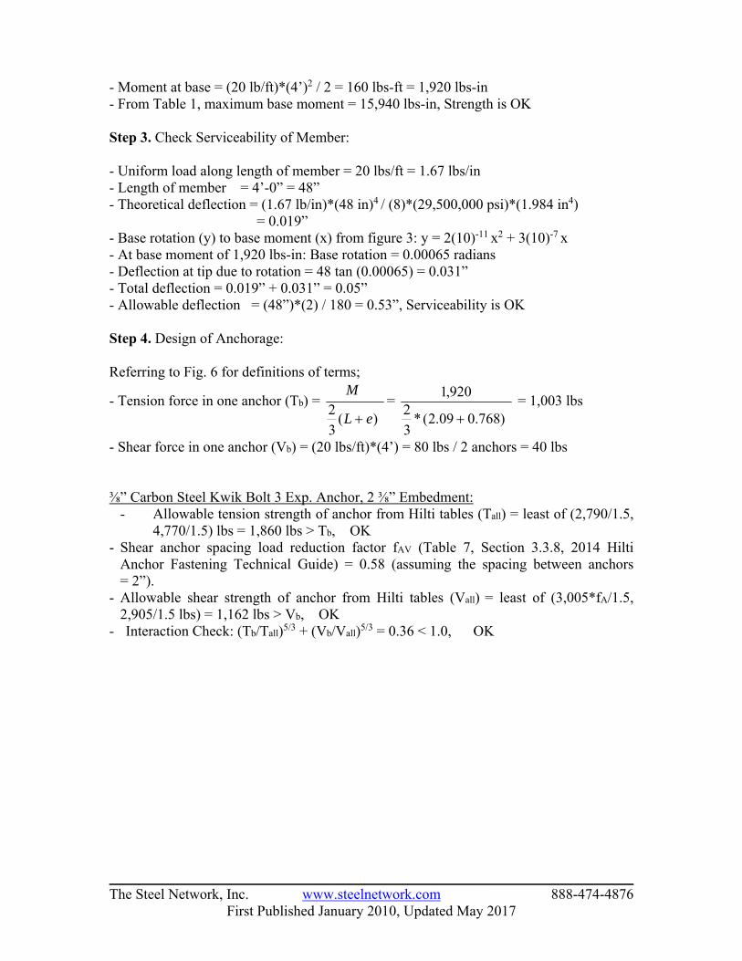
- Moment at base = (20 lb/ft)*(4’)2 / 2 = 160 lbs-ft = 1,920 lbs-in - From Table 1, maximum base moment = 15,940 lbs-in, Strength is OK Step 3. Check Serviceability of Member: - Uniform load along length of member = 20 lbs/ft = 1.67 lbs/in - Length of member = 4’-0” = 48” - Theoretical deflection = (1.67 lb/in)*(48 in)4 / (8)*(29,500,000 psi)*(1.984 in4) = 0.019” - Base rotation (y) to base moment (x) from figure 3: y = 2(10)-11 x2 + 3(10)-7 x - At base moment of 1,920 lbs-in: Base rotation = 0.00065 radians - Deflection at tip due to rotation = 48 tan (0.00065) = 0.031” - Total deflection = 0.019” + 0.031” = 0.05” - Allowable deflection = (48”)*(2) / 180 = 0.53”, Serviceability is OK Step 4. Design of Anchorage: Referring to Fig. 6 for definitions of terms;
- Tension force in one anchor (Tb) = )(
32 eL
M
=
)768.009.2(*32
920,1
= 1,003 lbs
- Shear force in one anchor (Vb) = (20 lbs/ft)*(4’) = 80 lbs / 2 anchors = 40 lbs ⅜” Carbon Steel Kwik Bolt 3 Exp. Anchor, 2 ⅜” Embedment:
- Allowable tension strength of anchor from Hilti tables (Tall) = least of (2,790/1.5, 4,770/1.5) lbs = 1,860 lbs > Tb, OK
- Shear anchor spacing load reduction factor fAV (Table 7, Section 3.3.8, 2014 Hilti Anchor Fastening Technical Guide) = 0.58 (assuming the spacing between anchors = 2”).
- Allowable shear strength of anchor from Hilti tables (Vall) = least of (3,005*fA/1.5, 2,905/1.5 lbs) = 1,162 lbs > Vb, OK
- Interaction Check: (Tb/Tall)5/3 + (Vb/Vall)5/3 = 0.36 < 1.0, OK
________________________________________________________________________ The Steel Network, Inc. www.steelnetwork.com 888-474-4876
First Published January 2010, Updated May 2017
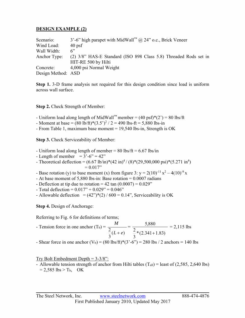
DESIGN EXAMPLE (2) Scenario: 3’-6” high parapet with MidWall™ @ 24” o.c., Brick Veneer Wind Load: 40 psf Wall Width: 6” Anchor Type: (2) 3/8” HAS-E Standard (ISO 898 Class 5.8) Threaded Rods set in
HIT-RE 500 by Hilti Concrete: 4,000 psi Normal Weight Design Method: ASD Step 1. 3-D frame analysis not required for this design condition since load is uniform across wall surface.
Step 2. Check Strength of Member: - Uniform load along length of MidWall™ member = (40 psf)*(2’) = 80 lbs/ft - Moment at base = (80 lb/ft)*(3.5’)2 / 2 = 490 lbs-ft = 5,880 lbs-in - From Table 1, maximum base moment = 19,540 lbs-in, Strength is OK Step 3. Check Serviceability of Member: - Uniform load along length of member = 80 lbs/ft = 6.67 lbs/in - Length of member = 3’-6” = 42” - Theoretical deflection = (6.67 lb/in)*(42 in)4 / (8)*(29,500,000 psi)*(5.271 in4) = 0.017” - Base rotation (y) to base moment (x) from figure 3: y = 2(10)-11 x2 – 4(10)-9 x - At base moment of 5,880 lbs-in: Base rotation = 0.0007 radians - Deflection at tip due to rotation = 42 tan (0.0007) = 0.029” - Total deflection = 0.017” + 0.029” = 0.046” - Allowable deflection = (42”)*(2) / 600 = 0.14”, Serviceability is OK Step 4. Design of Anchorage: Referring to Fig. 6 for definitions of terms;
- Tension force in one anchor (Tb) = )(
32 eL
M
=
)83.1341.2(*32
880,5
= 2,115 lbs
- Shear force in one anchor (Vb) = (80 lbs/ft)*(3’-6”) = 280 lbs / 2 anchors = 140 lbs Try Bolt Embedment Depth = 3-3/8”: - Allowable tension strength of anchor from Hilti tables (Tall) = least of (2,585, 2,640 lbs)
= 2,585 lbs > Tb, OK

________________________________________________________________________ The Steel Network, Inc. www.steelnetwork.com 888-474-4876
First Published January 2010, Updated May 2017
- Shear anchor spacing load reduction factor fA (Section 3.2.5, 2014 Hilti Anchor Fastening Technical Guide) = 0.3*(L/hef) + 0.55 = 0.3*(2.341 in/3.375 in) + 0.55 = 0.758
- Allowable shear strength of anchor from Hilti tables (Vall) = least of (4,460*fA, 1,360 lbs) = 1,360 lbs > Vb, OK
- Interaction Check: (Tb/Tall)5/3 + (Vb/Vall)5/3 = 0.74 < 1.0, OK DESIGN EXAMPLE (3) Scenario: 4’-0” Interior MidWall™ for guard application @ 30” o.c. Serviceability Limit: L/120 Load: 200 lb point load in any direction or 50 lb/ft linear load along top
of wall Wall Width: 3 ⅝” Anchor Type: (2) ⅜” HAS-R SS (AISI 304/316 SS) Threaded Rods set in HIT-
HY 200 by Hilti Concrete: 4,000 psi Normal Weight Step 1. 3-D Frame Analysis:

________________________________________________________________________ The Steel Network, Inc. www.steelnetwork.com 888-474-4876
First Published January 2010, Updated May 2017
Step 2. Check Strength of Member: - From analysis maximum load in MidWall™ member = 129.7 lbs - Moment at base = (129.7 lbs)*(4’) = 519 lbs-ft = 6226 lbs-in - From Table 1, maximum base moment = 15,940 lbs-in Strength is OK Step 3. Check Serviceability of Member: - Uniform load along length of member = 80 lbs/ft = 6.67 lbs/in - Length of member = 4’ 0” = 48” - Theoretical deflection = (129.7 lbs)*(48 in)3 / (3)*(29,500,000 psi)*(1.948 in4)
= 0.083” - Base rotation (y) to base moment (x) from figure 3: y = 2(10)-11 x2 + 3(10)-7 x - At base moment of 6226 lbs-in: Base rotation = 0.00264 radians - Deflection at tip due to rotation = 48 tan (0.00264) = 0.127” - Total deflection = 0.083” + 0.127” = 0.21” - Allowable deflection = (48”)*(2) / 120 = 0.80” Serviceability is OK Step 4. Design of Anchorage: Referring to Fig. 6 for definitions of terms;
- Tension force in one anchor (Tb) = )(
32 eL
M
=
)768.009.2(*32
226,6
= 3,268 lbs
- Shear force in one anchor (Vb) = 130 lbs / 2 anchors = 65 lbs

________________________________________________________________________ The Steel Network, Inc. www.steelnetwork.com 888-474-4876
First Published January 2010, Updated May 2017
Try Embedment Depth = 4 ½”: - Allowable tension strength of anchor from Hilti tables (Tall) = least of (4,317, 3,360 lbs)
= 3,360 lbs > Tb, OK - Shear anchor spacing load reduction factor fA (Table 42, Section 3.2.3, 2014 Hilti
Anchor Fastening Technical Guide) = 0.53 (assuming the spacing between anchors = 2”)
- Allowable shear strength of anchor from Hilti tables (Vall) = least of (5,167*fA, 1,550 lbs) = 1,550 lbs > Vb, OK
- Interaction Check: (Tb/Tall)5/3 + (Vb/Vall)5/3 = 0.96 < 1.0, OK CLOSING REMARKS
The use of MidWall™ in both residential and commercial framing streamlines the construction of a short wall. The International and Residential Building Codes give specific criteria for the design of several applications for which the MidWall™ may be used. The contents of this technical note provide full scale testing results, building code design requirements, and an overview of the analysis procedure for MidWall™. Steel Smart System (SSS Version 7), a cold-formed steel design software, automates this analysis procedure for quick and accurate framing options, including anchorage. For further information and download of SSS 7, visit www.steelsmartsystem.com. Users of the MidWall™ product will benefit from substantial cost savings associated with both material and labor.
REFERENCES ACI 318-11, “Building Code Requirements for Structural Concrete and Commentary”,
American Concrete Institute (ACI), 2011 Edition, Michigan. AISI S100-12, “North American Specification for the Design of Cold-Formed Steel
Structural Members”, American Iron and Steel Institute (AISI), 2012 Edition, Washington, DC.
ASI SSS7, “Steel Smart System Version 7”, Cold Formed Steel Design Software, Applied Science International, LLC, Durham, NC.
Hilti, “North American Product Technical Guide”, 2014 Edition, www.us.hilti.com. International Code Council (ICC). “International Building Code”, ICC Standard, 2015,
2012 and 2009 Editions, Virginia. International Code Council (ICC). “International Residential Code”, ICC Standard,
2015, 2012 and 2009 Editions, Virginia. Powers Fasteners. “Mechanical Anchors.” 2014 Edition, www.powers.com. Redhead Concrete Anchoring “Products” 2014 Edition, www.itw-redhead.com.