analog timer - cdn1.npcdn.net · analog timer part number description ttl - function sd: star-delta...
TRANSCRIPT
Ⅲ - 46 Industrial Controls Catalog www.kacon.co.kr Rev. 2/14Data subject may change without notice.
TTL SeriesAnalog Timer
Part Number Description
TTL - ❶ ❷ ❸
❶ Pin Type 8 : 8Pin Socket and Panel mounted
❷ Timing Mode A : A, A1, F1, I B : A, A1, B, F
❸ Supply Voltage 110/220VAC 24VDC 110VDC
Model Name TTL-8A, TTL-8B
Function Multi Timer
Timing Range 0.05sec ~ 100hour (Max. hours)
Rated Supply Voltage 100-240VAC 50/60Hz, 24VDC, 110VDC
Operating Voltage Range 90 ~ 110% of the Supply Voltage
Power ConsumptionApprox. 4.5VA (220VAC 60Hz) Approx. 1.5W (24VDC) Approx. 2.2W (110VDC)
Recovery Time Max. 200ms
Control Output
Contact Form Output by the Output Operation Mode, Temp (2C) Select Among Order (1C) + Temp (1C)
Contact Capacity NO : 250VAC 3A Resistance Load NC : 250VAC 2A Resistance Load
Life CycleMechanical Min. 10,000,000
Electrical Min. 100,000
Accuracy of operating time Max. ±0.3% FS
Setting Error ±5%
Influence of Voltage Max. ±0.5% FS
Influence of Temperature Max. ±2% FS
Insulation Resistance 100MΩ (for 500VDC)
Dielectric Resistance For 1 Minute Under 2000VAC 50/60Hz
Noise Immunity The Wave Form Noise (pulse 1us) ±2kV by the Noise Simulator
VibrationResistance
Malfunctional 10-55Hz(1 Minute Duration) Dual Wave Length 0.5mm 10 Minutes for Each Direction of X, Y, Z
Destruction 10-55Hz(1 Minute Duration) Dual Wave Length 0.75mm 1 Hour for Each Direction of X, Y, Z
ShockResistance
Malfunctional 100m/s2 (10G) Three Times for Each Direction of X, Y, Z
Destruction 300m/s2 (30G) Three Times for Each Direction of X, Y, Z
Ambient Temperature -10 ~ +55°C (with no icing)
Storage Temperature -25 ~ +65°C (with no icing)
Ambient Humidity 35 ~ 85%RH
Weight Approx. 100g (Except For The Packaging Material)
General Specification

Rev. 2/14Data subject may change without notice. www.kacon.co.kr Industrial Controls Catalog Ⅲ - 47
Data Processing
Product Selection
Timing Mode Part Number Voltage
A, A1, F1, I TTL-8ATTL-8A 110/220VAC
TTL-8A 24VDCTTL-8A 110VDC
A, A1, B, F TTL-8BTTL-8B 110/220VAC
TTL-8B 24VDCTTL-8B 110VDC
Diagram
TTL-8A, TTL-8B
[A], [F] output operation mode [A1], [B], [F1], [I] output operation mode
source
contact:
Resistive Load
source
contact:
Resistive Load
Time Range
Time Range Time Unit Setting Time Range
0.5
sec
0.05 ~ 0.5
1.0 0.1 ~ 1.0
5 0.5 ~ 5
10 1 ~ 10
0.5
min
0.05 ~ 0.5
1.0 0.1 ~ 1.0
5 0.5 ~ 5
10 1 ~ 10
Time Range Time Unit Setting Time Range
0.5
hour
0.05 ~ 0.5
1.0 0.1 ~ 1.0
5 0.5 ~ 5
10 1 ~ 10
0.5
10h
0.05 ~ 0.5
1.0 0.1 ~ 1.0
5 0.5 ~ 5
10 1 ~ 10
Data Processing

Ⅲ - 48 Industrial Controls Catalog www.kacon.co.kr Rev. 2/14Data subject may change without notice.
Timer Function
☞ Rotate the time unit shift switch and operation mode shift switch clockwise.☞ Time range shift switch cannot be rotated below 0.5 and above 10. Do not forcefully rotate the switch.
Output Operation Mode For Each Model
TTL-8A
Indication Operation Mode
A Power on Delay
A1 Power on Delay 1
F1 Flicker (ON)
I Interval
TTL-8B
Indication Operation Mode
A Power on Delay
A1 Power on Delay 1
B Power on Delay 2
F Flicker (OFF)
Dimension (mm)
Socket : K2BF08
Panel
Operation Mode Selector
Operation Mode Display Window
Time Unit Selector
TTL-8A (A, A1, F1 and I mode)TTL-8B (A, A1, B and F mode)
Power Indicator / Output Indicator(On-Delay NO Contact Operation : GreenOn-Delay NO Contact Open : Orange)
Time Setting Knob (Set Time)
Time Range Selector
Time Unit Display Window(sec, min, hour, 10h)
TTL SeriesAnalog Timer
Rev. 2/14Data subject may change without notice. www.kacon.co.kr Industrial Controls Catalog Ⅲ - 49
Data Processing
Data Processing
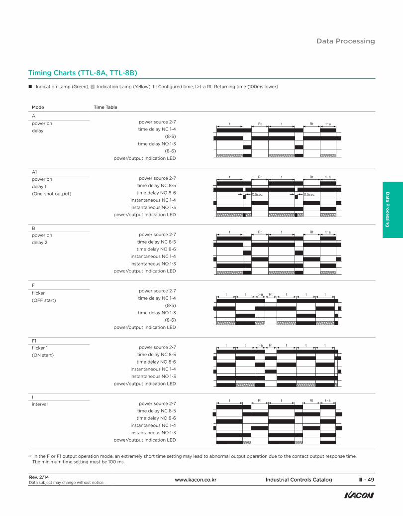
Timing Charts (TTL-8A, TTL-8B)
Mode Time Table
Apower source 2-7time delay NC 1-4
(8-5)time delay NO 1-3
(8-6)power/output Indication LED
power ondelay
A1power source 2-7
time delay NC 8-5time delay NO 8-6
instantaneous NC 1-4instantaneous NO 1-3
power/output Indication LED
0.5sec 0.5sec
power ondelay 1 (One-shot output)
Bpower source 2-7
time delay NC 8-5time delay NO 8-6
instantaneous NC 1-4instantaneous NO 1-3
power/output Indication LED
power ondelay 2
Fpower source 2-7time delay NC 1-4
(8-5)time delay NO 1-3
(8-6)power/output Indication LED
flicker (OFF start)
F1power source 2-7
time delay NC 8-5time delay NO 8-6
instantaneous NC 1-4instantaneous NO 1-3
power/output Indication LED
flicker 1(ON start)
Ipower source 2-7
time delay NC 8-5time delay NO 8-6
instantaneous NC 1-4instantaneous NO 1-3
power/output Indication LED
interval
☞ In the F or F1 output operation mode, an extremely short time setting may lead to abnormal output operation due to the contact output response time. The minimum time setting must be 100 ms.
■ : Indication Lamp (Green), ▨ :Indication Lamp (Yellow), t : Configured time, t>t-a Rt: Returning time (100ms lower)
Ⅲ - 50 Industrial Controls Catalog www.kacon.co.kr Rev. 2/14Data subject may change without notice.
TTL SeriesAnalog Timer
Part Number Description
TTL - ❶ ❷
❶ Function SD: Star-Delta operation
❷ Supply Voltage 100/240 VAC
General SpecificationModel Name TTL-SD
Function Star - Delta TIMER
Timing Range 0.05sec ~ 100sec (Maximum hours)
Rated Supply Voltage 100/240VAC 50/60Hz
Operation Voltage Range 90 ~ 110% of the Supply Voltage
Power Consumption approx. 4VA(240VAC 60Hz)
Recovery Time Max. 100ms
ControlOutput
Contact Form contact : SPST (1N/O), △ contact : SPST (1N/O)
Contact Capacity 250VAC 3A Resistance Load
life cycle Mechanical Min. 10,000,000
Electrical Max. 100,000 (250VAC 3A Resistance Load)
Repetition Tolerance Max. ±0.3%
Setting Error ±5%
Influence of Voltage Max. ±0.5%
Influence of Temperature Max. ±2%
Shift Time Tolerance ±25%
Insulation Resistance 100MΩ (for 500VDC)
Dielectric Resistance 2000VAC 50/60Hz for 1 minute
Noise Immunity the wave form noise (pulse 1us) ±2kV by the noise simulator
VibrationResistance
Malfunctional 10-55Hz(1 Minute Duration) Dual Wave Length 0.5mm 10 Minutes for Each Direction of X, Y, Z
Destruction 10-55Hz(1 Minute Duration) Dual Wave Length 0.75mm 1 Hour for Each Direction of X, Y, Z
ShockResistance
Malfunctional 100m/s2 (10G) Three Times for Each Direction of X, Y, Z
Destruction 300m/s2 (30G) Three Times for Each Direction of X, Y, Z
Ambient Temperature -10 ~ +55°C (with no icing)
Storage Temperature -25 ~ +65°C (with no icing)
Ambient Humidity 35 ~ 85%RH
Weight Approx. 100g (except for the packaging material)
Product Selection Dimension
Operating Mechanism Part Number
Analog Timer TTL-SD
(mm)
Y
socket : K2BF08
[Panel processing dimension diagram]
Panel
Rev. 2/14Data subject may change without notice. www.kacon.co.kr Industrial Controls Catalog Ⅲ - 51
Data Processing
Contact:250VAC 3A Resistive Load
source
source
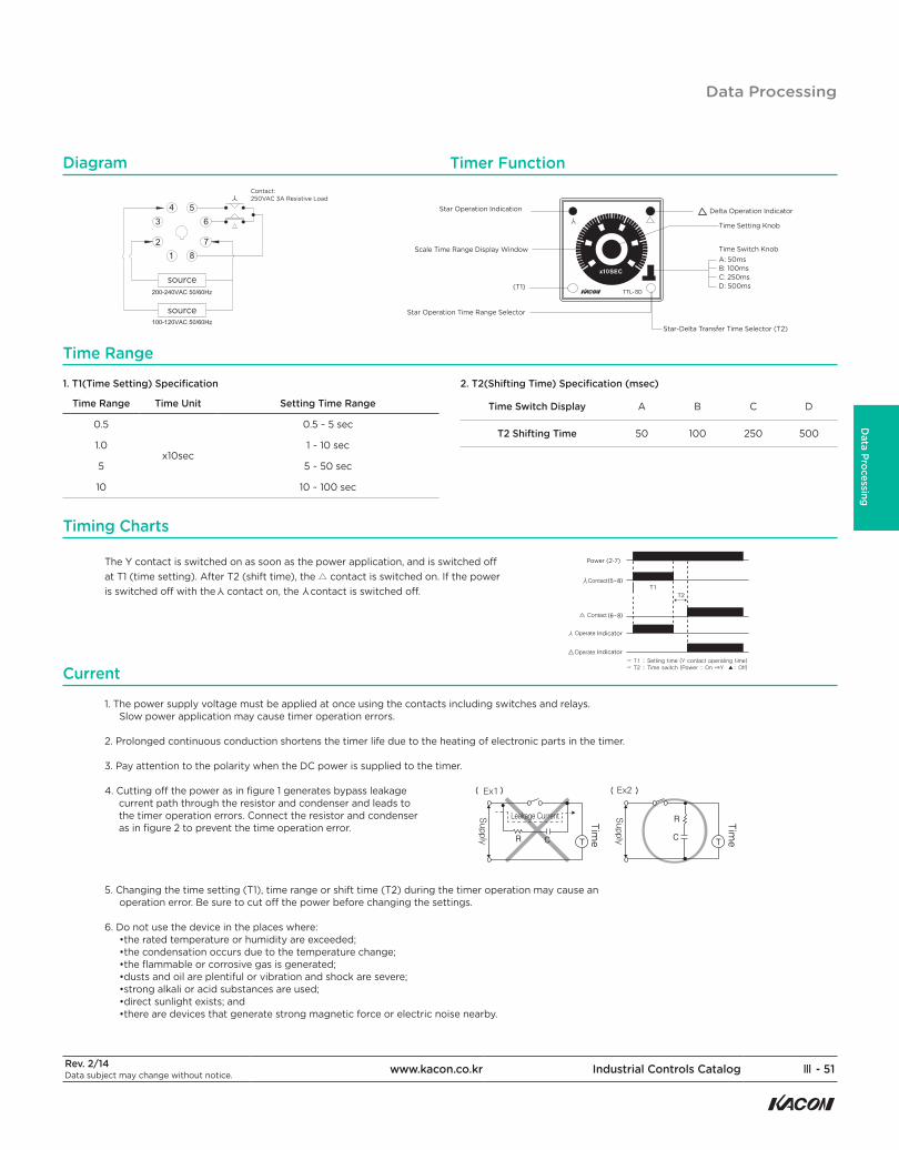
Diagram Timer Function
Current
Time Range
1. T1(Time Setting) Specification
Time Range Time Unit Setting Time Range
0.5
x10sec
0.5 ~ 5 sec
1.0 1 ~ 10 sec
5 5 ~ 50 sec
10 10 ~ 100 sec
2. T2(Shifting Time) Specification (msec)
Time Switch Display A B C D
T2 Shifting Time 50 100 250 500
Timing Charts
The Y contact is switched on as soon as the power application, and is switched off at T1 (time setting). After T2 (shift time), the △ contact is switched on. If the power is switched off with the contact on, the contact is switched off.
1. The power supply voltage must be applied at once using the contacts including switches and relays.Slow power application may cause timer operation errors.
2. Prolonged continuous conduction shortens the timer life due to the heating of electronic parts in the timer.
3. Pay attention to the polarity when the DC power is supplied to the timer.
4. Cutting off the power as in figure 1 generates bypass leakage current path through the resistor and condenser and leads to the timer operation errors. Connect the resistor and condenser as in figure 2 to prevent the time operation error.
5. Changing the time setting (T1), time range or shift time (T2) during the timer operation may cause anoperation error. Be sure to cut off the power before changing the settings.
6. Do not use the device in the places where:•the rated temperature or humidity are exceeded;•the condensation occurs due to the temperature change;•the flammable or corrosive gas is generated;•dusts and oil are plentiful or vibration and shock are severe;•strong alkali or acid substances are used;•direct sunlight exists; and•there are devices that generate strong magnetic force or electric noise nearby.
Time
Time
Star Operation Indication
Scale Time Range Display Window
(T1)
Star Operation Time Range Selector
Star-Delta Transfer Time Selector (T2)
Time Setting Knob
Time Switch KnobA: 50msB: 100msC: 250msD: 500ms
Delta Operation Indicator
Power (2-7)
Indicator
Indicator☞☞
Y Y
Data Processing
Ⅲ - 52 Industrial Controls Catalog www.kacon.co.kr Rev. 2/14Data subject may change without notice.
TTL SeriesAnalog Timer
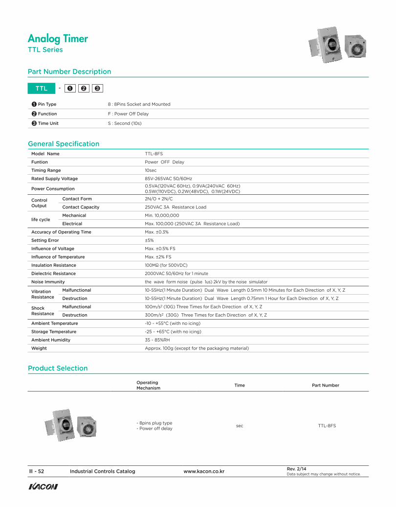
Model Name TTL-8FS
Funtion Power OFF Delay
Timing Range 10sec
Rated Supply Voltage 85V-265VAC 50/60Hz
Power Consumption 0.5VA(120VAC 60Hz), 0.9VA(240VAC 60Hz) 0.5W(110VDC), 0.2W(48VDC), 0.1W(24VDC)
Control Output
Contact Form 2N/O + 2N/C
Contact Capacity 250VAC 3A Resistance Load
life cycle Mechanical Min. 10,000,000
Electrical Max. 100,000 (250VAC 3A Resistance Load)
Accuracy of Operating Time Max. ±0.3%
Setting Error ±5%
Influence of Voltage Max. ±0.5% FS
Influence of Temperature Max. ±2% FS
Insulation Resistance 100MΩ (for 500VDC)
Dielectric Resistance 2000VAC 50/60Hz for 1 minute
Noise Immunity the wave form noise (pulse 1us) 2kV by the noise simulator
VibrationResistance
Malfunctional 10-55Hz(1 Minute Duration) Dual Wave Length 0.5mm 10 Minutes for Each Direction of X, Y, Z
Destruction 10-55Hz(1 Minute Duration) Dual Wave Length 0.75mm 1 Hour for Each Direction of X, Y, Z
ShockResistance
Malfunctional 100m/s2 (10G) Three Times for Each Direction of X, Y, Z
Destruction 300m/s2 (30G) Three Times for Each Direction of X, Y, Z
Ambient Temperature -10 ~ +55°C (with no icing)
Storage Temperature -25 ~ +65°C (with no icing)
Ambient Humidity 35 ~ 85%RH
Weight Approx. 100g (except for the packaging material)
Part Number Description
TTL - ❶ ❷ ❸
❶ Pin Type 8 : 8Pins Socket and Mounted
❷ Function F : Power Off Delay
❸ Time Unit S : Second (10s)
General Specification
Product Selection
OperatingMechanism Time Part Number
- 8pins plug type - Power off delay sec TTL-8FS

Rev. 2/14Data subject may change without notice. www.kacon.co.kr Industrial Controls Catalog Ⅲ - 53
Data Processing
Dimension (mm)
Diagram Timer Function
Caution
Contact:
Resistive Load
The a contact is switched on as soon as the power is supplied. After the set time (T) from the power off, the a contact is switched off.
☞
Power Indicator Output Indicator
Time Out Display Window
Scale Range Display Window
Time RangeSelector
Time Setting Knob
● Power supply The timer does not operate with the power supplied, but operate after the power is switched off.
● Noise 1) For the test of impulse voltage between the power terminals, a voltage of 2kV with a pulse width of 1μs is applied. For the test of
external noise voltage, a voltage of 1kV with a pulse width of 1μs is applied using a noise simulator. For the impulse noise voltage above these values, connect an AC MP condenser or oil condenser (0.1 ~ 1μF) between the power supply terminals. 2) When testing the withstand voltage, impulse voltage and insulation resistance with the device assembled with the control panel,
•Separate this product from the circuit completely.•Short all terminals (to prevent damage to the internal circuit when some units on the control panel have poor withstand voltage and insulation.)
● EnvironmentDo not use the device in the places where:•the rated temperature or humidity are exceeded;•the condensation occurs due to the temperature change;•the flammable or corrosive gas is generated;•dusts and oil are plentiful or vibration and shock are severe;•strong alkali or acid substances are used;•direct sunlight exists; and•there are devices that generate strong magnetic force or electric noise nearby.
☞
Timing Charts
Socket : K2BF08
[Panel processing dimension diagram]
Panel
Data Processing
Ⅲ - 54 Industrial Controls Catalog www.kacon.co.kr Rev. 2/14Data subject may change without notice.
TTL SeriesAnalog Timer
Part Number Description
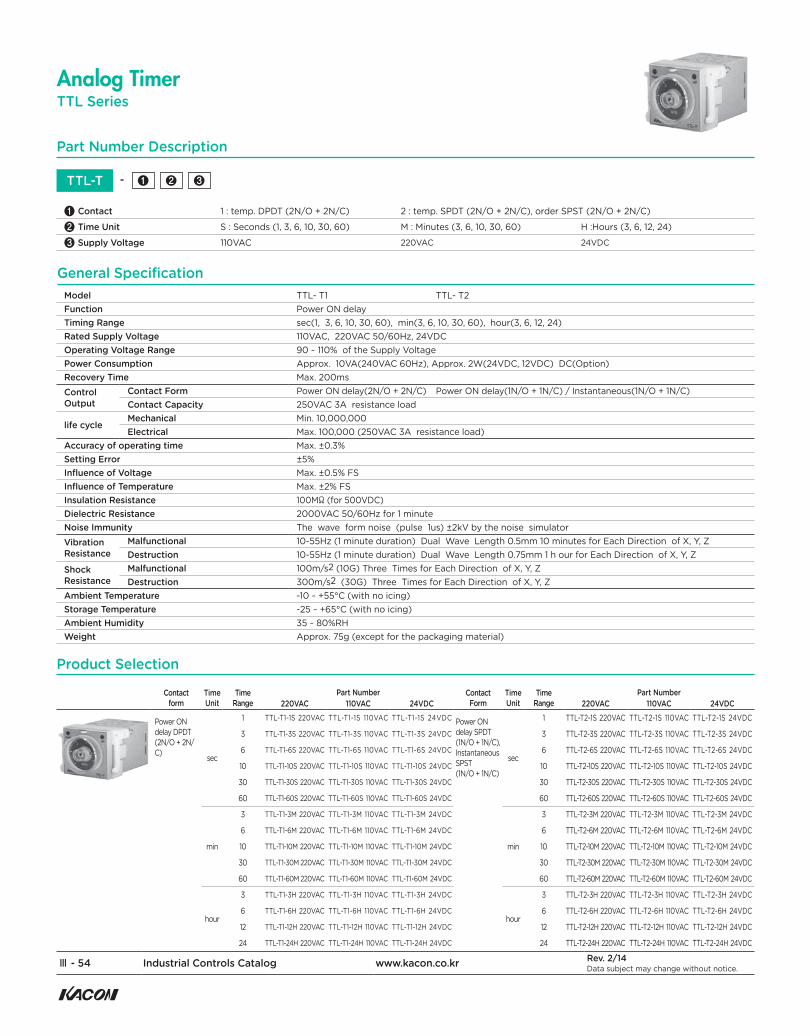
TTL-T - ❶ ❷ ❸
❶ Contact 1 : temp. DPDT (2N/O + 2N/C) 2 : temp. SPDT (2N/O + 2N/C), order SPST (2N/O + 2N/C)
❷ Time Unit S : Seconds (1, 3, 6, 10, 30, 60) M : Minutes (3, 6, 10, 30, 60) H :Hours (3, 6, 12, 24)
❸ Supply Voltage 110VAC 220VAC 24VDC
Model TTL- T1 TTL- T2Function Power ON delayTiming Range sec(1, 3, 6, 10, 30, 60), min(3, 6, 10, 30, 60), hour(3, 6, 12, 24)Rated Supply Voltage 110VAC, 220VAC 50/60Hz, 24VDCOperating Voltage Range 90 ~ 110% of the Supply VoltagePower Consumption Approx. 10VA(240VAC 60Hz), Approx. 2W(24VDC, 12VDC) DC(Option)Recovery Time Max. 200ms Control Output
Contact Form Power ON delay(2N/O + 2N/C) Power ON delay(1N/O + 1N/C) / Instantaneous(1N/O + 1N/C)Contact Capacity 250VAC 3A resistance load
life cycle Mechanical Min. 10,000,000Electrical Max. 100,000 (250VAC 3A resistance load)
Accuracy of operating time Max. ±0.3%Setting Error ±5%Influence of Voltage Max. ±0.5% FSInfluence of Temperature Max. ±2% FSInsulation Resistance 100MΩ (for 500VDC)Dielectric Resistance 2000VAC 50/60Hz for 1 minuteNoise Immunity The wave form noise (pulse 1us) ±2kV by the noise simulatorVibrationResistance
Malfunctional 10-55Hz (1 minute duration) Dual Wave Length 0.5mm 10 minutes for Each Direction of X, Y, ZDestruction 10-55Hz (1 minute duration) Dual Wave Length 0.75mm 1 h our for Each Direction of X, Y, Z
ShockResistance
Malfunctional 100m/s2 (10G) Three Times for Each Direction of X, Y, ZDestruction 300m/s2 (30G) Three Times for Each Direction of X, Y, Z
Ambient Temperature -10 ~ +55°C (with no icing)Storage Temperature -25 ~ +65°C (with no icing)Ambient Humidity 35 ~ 80%RHWeight Approx. 75g (except for the packaging material)
General Specification
Power ON delay DPDT (2N/O + 2N/C) sec
1 TTL-T1-1S 220VAC TTL-T1-1S 110VAC TTL-T1-1S 24VDC
3 TTL-T1-3S 220VAC TTL-T1-3S 110VAC TTL-T1-3S 24VDC
6 TTL-T1-6S 220VAC TTL-T1-6S 110VAC TTL-T1-6S 24VDC
10 TTL-T1-10S 220VAC TTL-T1-10S 110VAC TTL-T1-10S 24VDC
30 TTL-T1-30S 220VAC TTL-T1-30S 110VAC TTL-T1-30S 24VDC
60 TTL-T1-60S 220VAC TTL-T1-60S 110VAC TTL-T1-60S 24VDC
min
3 TTL-T1-3M 220VAC TTL-T1-3M 110VAC TTL-T1-3M 24VDC
6 TTL-T1-6M 220VAC TTL-T1-6M 110VAC TTL-T1-6M 24VDC
10 TTL-T1-10M 220VAC TTL-T1-10M 110VAC TTL-T1-10M 24VDC
30 TTL-T1-30M 220VAC TTL-T1-30M 110VAC TTL-T1-30M 24VDC
60 TTL-T1-60M 220VAC TTL-T1-60M 110VAC TTL-T1-60M 24VDC
hour
3 TTL-T1-3H 220VAC TTL-T1-3H 110VAC TTL-T1-3H 24VDC
6 TTL-T1-6H 220VAC TTL-T1-6H 110VAC TTL-T1-6H 24VDC
12 TTL-T1-12H 220VAC TTL-T1-12H 110VAC TTL-T1-12H 24VDC
24 TTL-T1-24H 220VAC TTL-T1-24H 110VAC TTL-T1-24H 24VDC
Power ON delay SPDT (1N/O + 1N/C),Instantaneous SPST (1N/O + 1N/C)
sec
1 TTL-T2-1S 220VAC TTL-T2-1S 110VAC TTL-T2-1S 24VDC
3 TTL-T2-3S 220VAC TTL-T2-3S 110VAC TTL-T2-3S 24VDC
6 TTL-T2-6S 220VAC TTL-T2-6S 110VAC TTL-T2-6S 24VDC
10 TTL-T2-10S 220VAC TTL-T2-10S 110VAC TTL-T2-10S 24VDC
30 TTL-T2-30S 220VAC TTL-T2-30S 110VAC TTL-T2-30S 24VDC
60 TTL-T2-60S 220VAC TTL-T2-60S 110VAC TTL-T2-60S 24VDC
min
3 TTL-T2-3M 220VAC TTL-T2-3M 110VAC TTL-T2-3M 24VDC
6 TTL-T2-6M 220VAC TTL-T2-6M 110VAC TTL-T2-6M 24VDC
10 TTL-T2-10M 220VAC TTL-T2-10M 110VAC TTL-T2-10M 24VDC
30 TTL-T2-30M 220VAC TTL-T2-30M 110VAC TTL-T2-30M 24VDC
60 TTL-T2-60M 220VAC TTL-T2-60M 110VAC TTL-T2-60M 24VDC
hour
3 TTL-T2-3H 220VAC TTL-T2-3H 110VAC TTL-T2-3H 24VDC
6 TTL-T2-6H 220VAC TTL-T2-6H 110VAC TTL-T2-6H 24VDC
12 TTL-T2-12H 220VAC TTL-T2-12H 110VAC TTL-T2-12H 24VDC
24 TTL-T2-24H 220VAC TTL-T2-24H 110VAC TTL-T2-24H 24VDC
Contactform
TimeUnit
TimeRange
Part Number220VAC 110VAC 24VDC
ContactForm
TimeUnit
TimeRange
Part Number220VAC 110VAC 24VDC
Product Selection
Rev. 2/14Data subject may change without notice. www.kacon.co.kr Industrial Controls Catalog Ⅲ - 55
Data Processing
Scale Range Display Window
socket : K2BF08
[Panel processing dimension diagram]
Panel
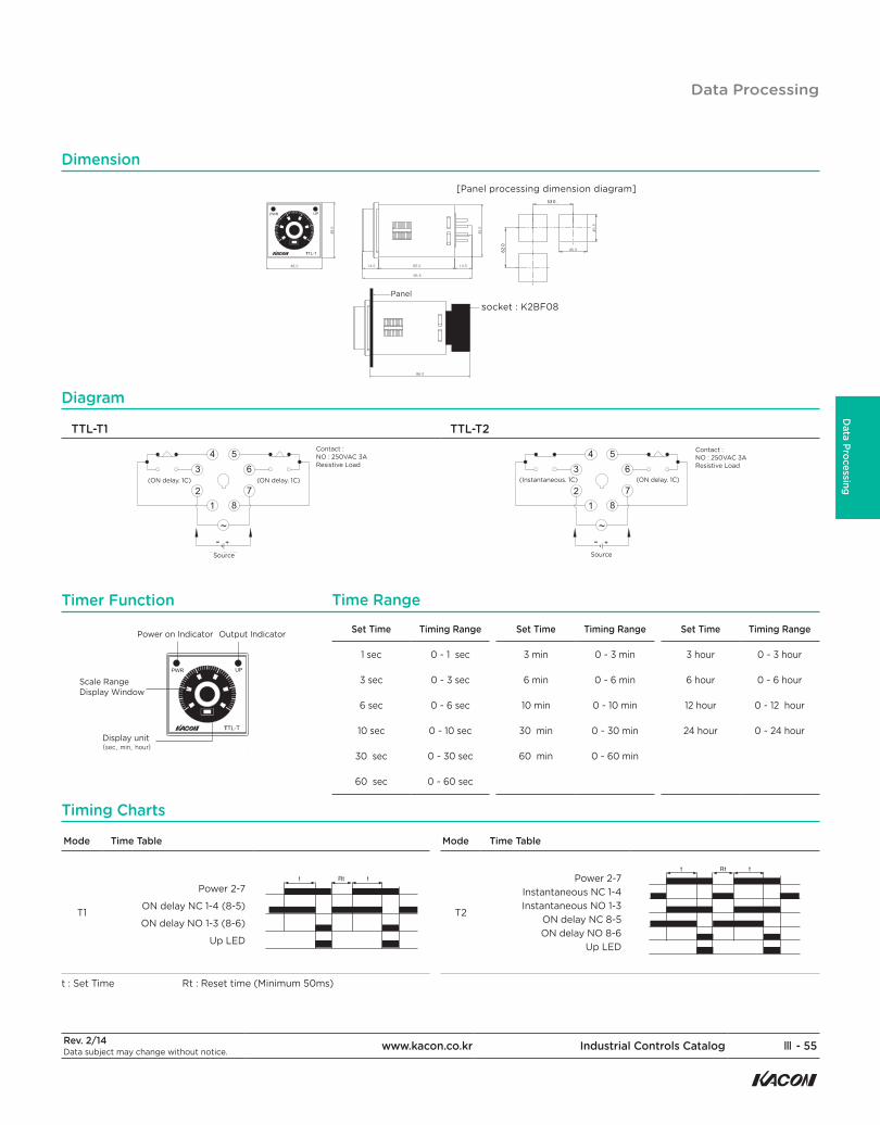
TTL-T1 TTL-T2Contact :NO : 250VAC 3AResistive Load
Source
(ON delay. 1C) (ON delay. 1C)
Contact :NO : 250VAC 3AResistive Load
Source
(ON delay. 1C)(Instantaneous. 1C)
Dimension
Diagram
Power on Indicator
Display unit
Output Indicator
Timer Function
Set Time Timing Range
1 sec 0 ~ 1 sec
3 sec 0 ~ 3 sec
6 sec 0 ~ 6 sec
10 sec 0 ~ 10 sec
30 sec 0 ~ 30 sec
60 sec 0 ~ 60 sec
Set Time Timing Range
3 min 0 ~ 3 min
6 min 0 ~ 6 min
10 min 0 ~ 10 min
30 min 0 ~ 30 min
60 min 0 ~ 60 min
Set Time Timing Range
3 hour 0 ~ 3 hour
6 hour 0 ~ 6 hour
12 hour 0 ~ 12 hour
24 hour 0 ~ 24 hour
Time Range
Mode Time Table
T1
Power 2-7
ON delay NC 1-4 (8-5)
ON delay NO 1-3 (8-6)
Up LED
t : Set Time Rt : Reset time (Minimum 50ms)
Mode Time Table
T2
Power 2-7Instantaneous NC 1-4Instantaneous NO 1-3
ON delay NC 8-5ON delay NO 8-6
Up LED
Timing Charts
Data Processing
Ⅲ - 56 Industrial Controls Catalog www.kacon.co.kr Rev. 2/14Data subject may change without notice.
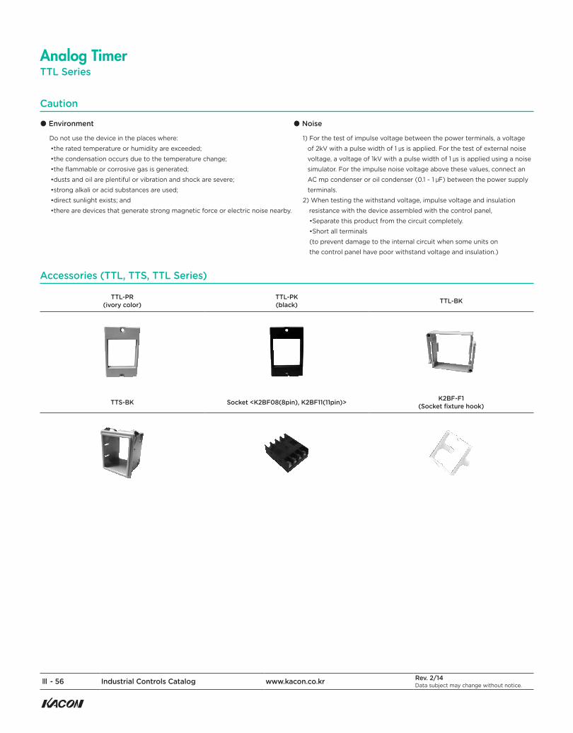
TTL-PR(ivory color)
TTL-PK(black) TTL-BK
TTS-BK Socket <K2BF08(8pin), K2BF11(11pin)> K2BF-F1(Socket fixture hook)
● Environment
Do not use the device in the places where:•the rated temperature or humidity are exceeded;•the condensation occurs due to the temperature change;•the flammable or corrosive gas is generated;•dusts and oil are plentiful or vibration and shock are severe;•strong alkali or acid substances are used;•direct sunlight exists; and•there are devices that generate strong magnetic force or electric noise nearby.
● Noise
1) For the test of impulse voltage between the power terminals, a voltage of 2kV with a pulse width of 1 μs is applied. For the test of external noise voltage, a voltage of 1kV with a pulse width of 1 μs is applied using a noise simulator. For the impulse noise voltage above these values, connect an AC mp condenser or oil condenser (0.1 ~ 1 μF) between the power supply terminals.
2) When testing the withstand voltage, impulse voltage and insulation resistance with the device assembled with the control panel,•Separate this product from the circuit completely.•Short all terminals (to prevent damage to the internal circuit when some units on the control panel have poor withstand voltage and insulation.)
Caution
Accessories (TTL, TTS, TTL Series)
TTL SeriesAnalog Timer
Rev. 2/14Data subject may change without notice. www.kacon.co.kr Industrial Controls Catalog Ⅲ - 57
Data Processing
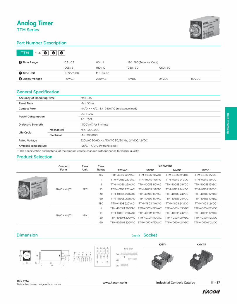
TTM SeriesAnalog Timer
Part Number Description
TTM - 4 ❶ ❷ ❸
❶ Time Range 0.5 : 0.5 001 : 1 180 : 180(Seconds Only)
005 : 5 010 : 10 030 : 30 060 : 60
❷ Time Unit S : Seconds M : Minute
❸ Supply Voltage 110VAC 220VAC 12VDC 24VDC 110VDC
Accuracy of Operating Time Max. ±1%
Reset Time Max. 50ms
Contact Form 4N/O + 4N/C, 3A 240VAC (resistance load)
Power ConsumptionDC : 1.2W
AC : 2VA
Dielectric Strength 1,500VAC for 1 minute
Life Cycle Mechanical Min. 1,000,000
Electrical Min. 200,000
Rated Voltage 220VAC 50/60 Hz, 110VAC 50/60 Hz, 24VDC. 12VDC
Ambient Temperature -25°C ~ +70°C (with no icing)
☞ The specification and material of the product can be changed without notice for higher quality.
General Specification
4N/O + 4N/C SEC
0.5 TTM-40.5S 220VAC TTM-40.5S 110VAC TTM-40.5S 24VDC TTM-40.5S 12VDC
1 TTM-4001S 220VAC TTM-4001S 110VAC TTM-4001S 24VDC TTM-4001S 12VDC
5 TTM-4005S 220VAC TTM-4005S 110VAC TTM-4005S 24VDC TTM-4005S 12VDC
10 TTM-4010S 220VAC TTM-4010S 110VAC TTM-4010S 24VDC TTM-4010S 12VDC
30 TTM-4030S 220VAC TTM-4030S 110VAC TTM-4030S 24VDC TTM-4030S 12VDC
60 TTM-4060S 220VAC TTM-4060S 110VAC TTM-4060S 24VDC TTM-4060S 12VDC
180 TTM-4180S 220VAC TTM-4180S 110VAC TTM-4180S 24VDC TTM-4180S 12VDC
4N/O + 4N/C MIN
5 TTM-4005M 220VAC TTM-4005M 110VAC TTM-4005M 24VDC TTM-4005M 12VDC
10 TTM-4010M 220VAC TTM-4010M 110VAC TTM-4010M 24VDC TTM-4010M 12VDC
30 TTM-4030M 220VAC TTM-4030M 110VAC TTM-4030M 24VDC TTM-4030M 12VDC
60 TTM-4060M 220VAC TTM-4060M 110VAC TTM-4060M 24VDC TTM-4060M 12VDC
ContactForm
TimeUnit
TimeRange
Part Number220VAC 110VAC 24VDC 12VDC
Product Selection
KMY4 KMY4STime Chart
Dimension Socket(mm)
Ⅲ - 58 Industrial Controls Catalog www.kacon.co.kr Rev. 2/14Data subject may change without notice.
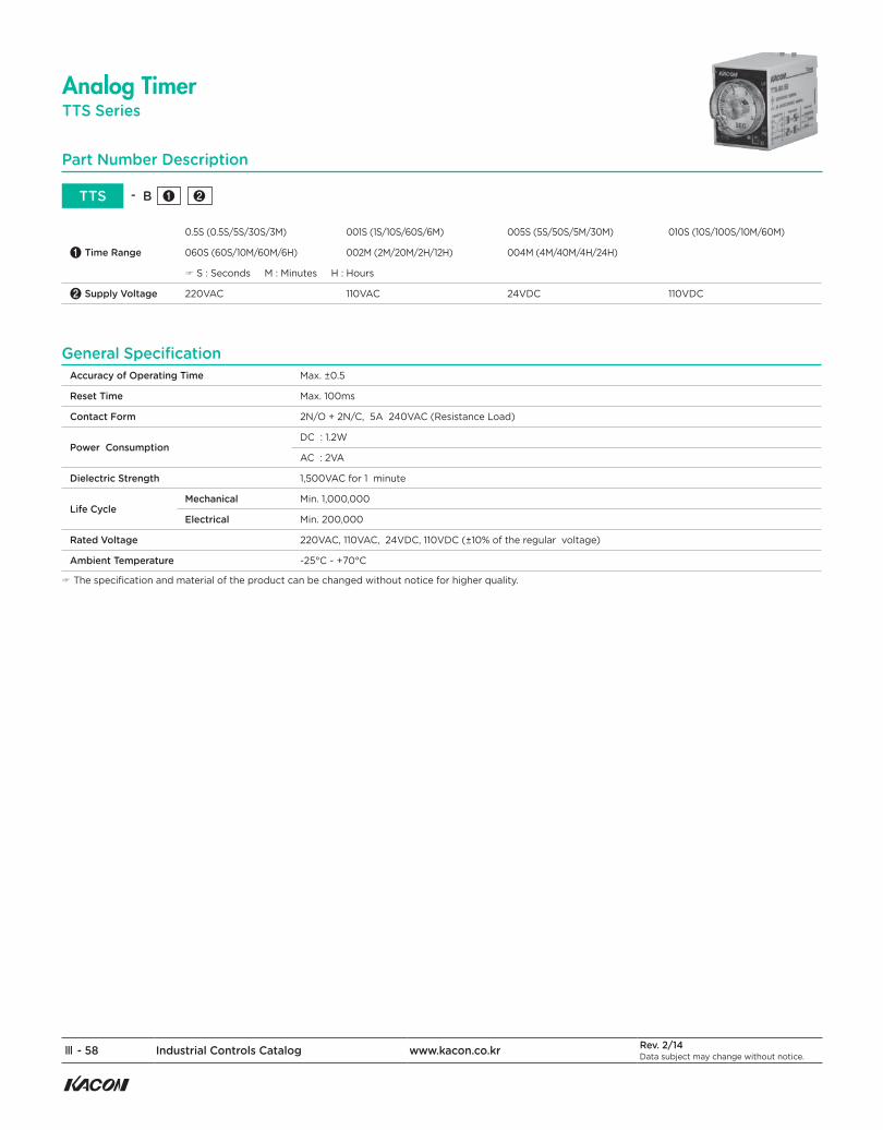
TTS SeriesAnalog Timer
Part Number Description
TTS - B ❶ ❷
❶ Time Range
0.5S (0.5S/5S/30S/3M) 001S (1S/10S/60S/6M) 005S (5S/50S/5M/30M) 010S (10S/100S/10M/60M)
060S (60S/10M/60M/6H) 002M (2M/20M/2H/12H) 004M (4M/40M/4H/24H)
☞ S : Seconds M : Minutes H : Hours
❷ Supply Voltage 220VAC 110VAC 24VDC 110VDC
Accuracy of Operating Time Max. ±0.5
Reset Time Max. 100ms
Contact Form 2N/O + 2N/C, 5A 240VAC (Resistance Load)
Power ConsumptionDC : 1.2W
AC : 2VA
Dielectric Strength 1,500VAC for 1 minute
Life CycleMechanical Min. 1,000,000
Electrical Min. 200,000
Rated Voltage 220VAC, 110VAC, 24VDC, 110VDC (±10% of the regular voltage)
Ambient Temperature -25°C ~ +70°C
☞ The specification and material of the product can be changed without notice for higher quality.
General Specification
Rev. 2/14Data subject may change without notice. www.kacon.co.kr Industrial Controls Catalog Ⅲ - 59
Data Processing
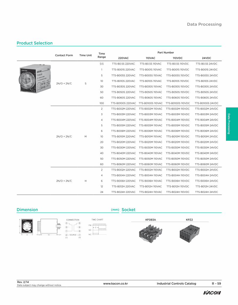
2N/O + 2N/C S
0.5 TTS-B0.5S 220VAC TTS-B0.5S 110VAC TTS-B0.5S 110VDC TTS-B0.5S 24VDC
1 TTS-B001S 220VAC TTS-B001S 110VAC TTS-B001S 110VDC TTS-B001S 24VDC
5 TTS-B005S 220VAC TTS-B005S 110VAC TTS-B005S 110VDC TTS-B005S 24VDC
10 TTS-B010S 220VAC TTS-B010S 110VAC TTS-B010S 110VDC TTS-B010S 24VDC
30 TTS-B030S 220VAC TTS-B030S 110VAC TTS-B030S 110VDC TTS-B030S 24VDC
50 TTS-B050S 220VAC TTS-B050S 110VAC TTS-B050S 110VDC TTS-B050S 24VDC
60 TTS-B060S 220VAC TTS-B060S 110VAC TTS-B060S 110VDC TTS-B060S 24VDC
100 TTS-B0100S 220VAC TTS-B0100S 110VAC TTS-B0100S 110VDC TTS-B0100S 24VDC
2N/O + 2N/C M
2 TTS-B002M 220VAC TTS-B002M 110VAC TTS-B002M 110VDC TTS-B002M 24VDC
3 TTS-B003M 220VAC TTS-B003M 110VAC TTS-B003M 110VDC TTS-B003M 24VDC
4 TTS-B004M 220VAC TTS-B004M 110VAC TTS-B004M 110VDC TTS-B004M 24VDC
5 TTS-B005M 220VAC TTS-B005M 110VAC TTS-B005M 110VDC TTS-B005M 24VDC
6 TTS-B006M 220VAC TTS-B006M 110VAC TTS-B006M 110VDC TTS-B006M 24VDC
10 TTS-B010M 220VAC TTS-B010M 110VAC TTS-B010M 110VDC TTS-B010M 24VDC
20 TTS-B020M 220VAC TTS-B020M 110VAC TTS-B020M 110VDC TTS-B020M 24VDC
30 TTS-B030M 220VAC TTS-B030M 110VAC TTS-B030M 110VDC TTS-B030M 24VDC
40 TTS-B040M 220VAC TTS-B040M 110VAC TTS-B040M 110VDC TTS-B040M 24VDC
50 TTS-B050M 220VAC TTS-B050M 110VAC TTS-B050M 110VDC TTS-B050M 24VDC
60 TTS-B060M 220VAC TTS-B060M 110VAC TTS-B060M 110VDC TTS-B060M 24VDC
2N/O + 2N/C H
2 TTS-B002H 220VAC TTS-B002H 110VAC TTS-B002H 110VDC TTS-B002H 24VDC
4 TTS-B004H 220VAC TTS-B004H 110VAC TTS-B004H 110VDC TTS-B004H 24VDC
6 TTS-B006H 220VAC TTS-B006H 110VAC TTS-B006H 110VDC TTS-B006H 24VDC
12 TTS-B012H 220VAC TTS-B012H 110VAC TTS-B012H 110VDC TTS-B012H 24VDC
24 TTS-B024H 220VAC TTS-B024H 110VAC TTS-B024H 110VDC TTS-B024H 24VDC
Product Selection
KF083A KPZ2
Dimension Socket(mm)
Contact Form Time Unit Time Range
Part Number
220VAC 110VAC 110VDC 24VDC
Data Processing