analog 6 channel scanning w devices digital thermometer€¦ · w devices i features...
TRANSCRIPT
,. ANALOGW DEVICES
I
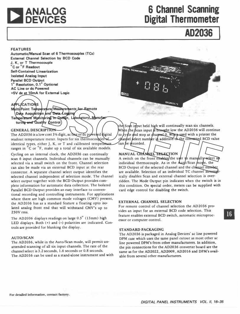
FEATURESAutomaticlManual Scan of 6 Thermocouples (TCs)External Channel Selection by BCD CodeJ, K, or T Thermocouple°c or of ReadoutSelf-Contained LinearizationIsolated Analog InputParallel BCD Output1° Resolution, 0.1° OptionalAC Line or de Powered+5V de at 10mA for External Logic
APPLICATIONSMulti-Point Temperature Measurements for Remote
Data Acquisition and Data LoggingTemperature Monitoring in Design, Laboratory, Manufac-
turing and Quality Control
GENERAL DESCRIPTIONThe AD2036 is a low cost 3~ digit, ac line or dc powered digitalreadout temperatUre meter. Inputs for six thermocouples of
identical 7pes, either J, K, or T and calibrated temperatUreranges in C or of, make up a total of six available models.
Cycling on an internal clock, the AD2036 can continuallyscan 6 input channels. Individual channels can be manuallyselected via a small switch on the front. Channel selectioncan also be made via an external BCD input at the rearconnector. A separate channel select output identifies theselected channel independent of selection mode. The channelselect output together with the BCD Output provides com-plete information for automatic data collection. The IsolatedParallel BCD Output provides an easy interface to conven-tional recording and controlling instruments. For applicationswhere there are high common mode voltages (CMV) present,the AD2036 has as a standard featUre a floating opto iso-lated analog front end that will withstand CMV's up to2S0V rms.
The AD2036 displays readings on large 0.5" (13mm) highLED displays. Both (+) and (-) polarities are indicated. Con-trols are provided for blanking the display.
AUTO/SCANThe AD2036, while in the Auto/Scan mode, will permit un-attended scanning of all six input channels. The rate of thechannel select is 3.2 seconds, 1.6 seconds or 0.8 seconds.The AD2036 can be used as a stand-alone instrument and with
For detailed information, contact factory.
6 ChannelScanningDigitalThermometer
AD2036 I
the Scan input held high will continually scan six channels.When the Scan input is brought low the AD2036 will continueto cycle and stop at channel O.When used with a printer thechannel select number in addition to the converted BCD valuecan be recorded.
MANUAL CHANNEL SELECTIONA switch on the front enables the user to manually select anindividual thermocouple. As in the Auto/Scan mode, theBCD Output of the selected channel and the channel numberare available. Selection of an individual TC channel automat-ically disables Scan and external channel selection is over-ridden. The Mode Output pin indicates when the switch is inthis condition~ On special order, meters can be supplied withcard edge control for disabling the switch.
EXTERNAL CHANNEL SELECTIONFor remote control of channel selection the AD2036 pro-vides an input for an external BCD code selection. ThisfeatUre enables external BCD switch, automatic microproc-essor or computer control.
IIISTANDARD PACKAGINGThe AD2036 is packaged in Analog Devices' ac line poweredDPM case which uses the same panel cutout as most other acline powered DPM's from other manufacturers. In addition,the pin connections for the AD2036 converter board are thesame as for the AD2022, AD2009, AD2016 and DPM's avail-able from several other manufactUrers.
DIGITALPANELINSTRUMENTS VOL. /I, 7~35
OBSOLETE
SPECIFICATIONS(typical. +25°Candnominallinevoltageunl.. otherwi. specified)
T -100 to 00 to 250
250 to 400
t1.3t1.5t2.0
T -148 to 3232 to 450
450 to 752
:t2.3t2.7t3.6
Channel BCDOucputs (CMOSfITL Colllpatibk 2 TIL Loads) -BCDChannel number data outputs are:positive trUe.
Mode OutPut (CMOSfITL Compatible 2 TIL Loads) . Logic "I" indicateschannel selection is by switch. Logic "0" indicates selecrion is by scanneror external control, uteful in microcomputer interface.
DataReady(DataReady)lCMOSfITLComoatible2 TIL Loads)-Logic"I" ("0") indicates data from Temperature Card is ready. Data remainsvalid until next eloCkpulse (198ms).
Soare:Inverter OutPut (CMOSfITL Comoatible 2 TIL Loads) . Spare in.verter supplied for customer convenience.
Clock OUT (CMOS.TIL Compatible 2 TIL Loads) -Indicates E.O.C.When Clock pulse is high latches are being updated, data is invalid. Datais valid on neprive going edF. Clock OUT pull<: is disabled when DATAHOLD line is low.
Anal", Output - Nonlinear Error to.5'" tlmV
VOUT, °c : (1. 784mV tC) TemperaturcVOUT, of: (0.99ImVtF)(T-32)
TEMPERATURE RANGE2
. 0 t~ +500C ?ferating
. -25 C to +85 C StoragePOWER OUTPUT
. +5V dc@ 10mAPOWER INPUT
. AC line 50 - 400Hz, See Voltage Options below. Power Consumption - 5.8W @ 50 - 400llz. 12V dc +20%- 10%,4.8W. 5Vdct S%,4W
CALIBRATION ADJUSTMENTS. Span. Zero. Recommended Recalibration Interval, six months
DISPLAY OUTPUT
. Lipt emittinc diode (LED). seven segment display readoutS, 0.5"(Umm) hip for 3 data diaits. 100!!.oYCtranF and polarity indic".tion. Overload> 1999 indicated by flashing display, polarity remainsvalid. Tbere is no overload indication for out of range readings.
. Decimal points (3) selectable at input connector.
. Display Blanking
SIGNAL INPUT. Input Impedance. looMO. Bias Current. IOnA
. Overvoltage Protection BetWCCnChannels, tl8V peak max. Common Mode Voltage. t350V peak max
. CMVBetween Channels, t6V peak max
. TemperatUre Coefficient' Span, +temp, lOOppm;-temp, 120ppmZero. 0.03degrees/degrec C or F .
. Settling Time to Rated Accuracy. 2.0 seconds (full span step input)
. Normal Mode Rejection. 6OdB at 50 - 400Hz
. Common Mode Rejection, 12OdB@2S0V rms max CMV(BetWeenTC's and digital gnd), dvan/dt<1O6V/sec, 2500 imbalance
CONVERSION RATE. 5 conversions per second.Hold and read on command
CONTROL INPUTS
Display Blankil1l (TIL Compatible 3 LSTTL Load) - Logic "0" or
grounding blanks entire display except for decimal pointS; Logic "I"or open circuit for normal operation. Display blanking has no effccton output data. Display is valid immediately upon removal of blank-ing input.
Converter Hold (CMOS TTL Compatible. I LSTTL Load) - Logic "0"or grounding causes DPM to cease conversions and display data fromlast conversion; Logic "I" or open circuit for nonnal operation. After"Convener Hold" is removed, one or two conversions arc needed beforereading and BCD are valid.
Decimal Points (Not TIL Compatible) . Logic "0" or grounding illumi-nates desired decimal point. External drive circuitry must sink 35mApeak at a 25% duty cycle. when decimal point is illuminated.
Dai'aHOid (TTL Compatiblc I TTL Loacj)- Logic "0" or groundinginhibits updating of latch cd paralld output data of AD2036. Logic "I"or open circuit allows data to be updated after each DPM conversion.This input has no effecI on the normal conversion of the DPM and itSdisplay.
Scanner Enable (CMOS/TTL Compatible I LSTTL Load). Logic "I" will
enable Scanner to control the channel selection. External channd inputBCD lines can remain connected. A Logic "0" enables external channelselection.
SIZE. 3.92" x 1.67"H x 5.80"D (100 x 42 x 147mm). Panel cutout 3.930" x 1.682" (99.8 x 42.7mm)
WEIGHT. 1.25 pounds (0.568 kg)
DISPLAY LENS.Lens 22-1, Red, °Cwith ADI LogoLens 22-2. Red, of with AD! Logo
Lens 23.1, Red, °c without ADI LogoLens 23-2. Red, of without ADI logo
CONNECTORS(2)2 each,.30 pin, 0.156" spacing card edge conneborViking 2VK15D/I-2 or equivalent.Optional, Order ACI501.
THERMOCOUPLE TYPE>
~ f
ORDERING GUIDE
AD2036 0 - 0
- ENTER J0 0 0
Scan (ScaIll.LCMOS/TTLComoallllie. 1 L~rTL Luad) . A I.~ic "I" ("0")
tOI <4 seconds wllllnlllalC a scan uf SIXchannels. Tu us<: Scan input, th..Scan InpUt must be . logic "0". Both inputs have debouncc circuitry. Amomentary scan pulse while in the switch or external selection mode will
initiate a sequencc of SIXreadings of the channel that IS addressed then Stop.
Channel BCD Input (CMOSfITL Compatible I LSTTL Load) -Logic "0"on Scanner Enable will allow use of external control. All other controlinputs remain the same.
Channcllncrement (CMOSfITL Compatible I LSTTL Load) . Positive
going edge will ,nitiate sequence to the next channel.
~nverter Input (CMOS TTL Compatible I LSTTL Load) . Spareinverter supplied for Customer convenience.
- ENTER#
- ENTER#
- ENTER#
- ENTER#
NOTES
, For 0.1' '_lotion accuracy remain, the aamc. R..". is limited to200.0'
. Guaranteed'Only on. option may be opecificd..Lena 22 is ..pplicd II no lena option is ope<iftcd.
DATA OUTPUTS
Isolated Parallel BCD OumutS -3BCDdigits, Overrange,Overload andData Ready OutpUtS (TTL Compatible. 4 TTL Loads). BCD data OUt.
puts arc latched positive true logic. Overrange Output is logic "I" fotdata display greater than 999. Overload Output is Logic "0" for inputSgreat~r than full scale range, Logic "I" when other data outputS arevalid. Polarity Output (TTL Compatible, 4 TTL Loads latched) ind~
cates positive pol amy when high (Logic "I"). Digital outputs arc fullyIsolated from Input circuitry; all logic levels are referenced to digitalground.
Spcc riona lubject to ch...p without nOtice.
VOL. 1/, 16-36 DIGITALPANEL INSTRUMENTS
TYPES OF THERMOCOUPLE lTC&), J. K, or T
ACCURACY'
°c Error of ErrortLSB tLSB
J -60toO t1.4 J -76 to 32 t2.50 to 500 t1.4 32 to 932 t2.5
500 to 760 t2.2 932 to 1400 t4.0
K -60 to 0 t1.4 K -76 to 32 t2.50 to ISO t1.4 32 to 302 t2.5
150 to 1350 t2.6 302 to 2000 t4.7
POWER INPUT>117V ac tlO%
1\
220V ac tl0%looV ac tlO%240V ac tlO%5V de tS'"12V de +20%,-10%
SCAN RATE>3.2scc:
H1.6see0.8sec
DEGREE READOUT>°c
!of
RESOLUTION>1.0°
I0.1°
OBSOLETE

ApplyingtheAD203.6.
UNLINEARIZED ANALOG OUTPUT
~{
--------
CHANNEL
{
'
.BCDINPUT,
CHANNEL INCREMENTSCAN~DATA'ReADY
DA.TA REA
DIGITALSCANNER
SPARE~INVERTER
ANALOG
=~E
A~IMARYLOGIC
~E1
CLOCKIN
- - E)<TERNALCONNECTION - -CLOCK OUT
Figure 1. Block Diagram
DESIGNED AND BUILT FOR RELIABILITY
Even beyond the inherent advantag~s of the LSI IC designand LED displays, the AD2036 has had extreme care takenin its design and manufacture to insure reliability. Manu-facturing processes are monitored by continual qualityassurance inspections to insure proper workmanship andtesting. Automatic equipment is used to test each DPM, bothat the board level and at final assembly, to assure fault freeperformance. And, prior to shipment, each AD2036 mustpass one full week of failure-free +SOOCcycled powerburn-in.
APPLYING THE AD2036
~Kriprlonof~rlon
The AD2036 Block Diagram is shown in Figure 1. Thermo-couple selection is made by the CMOS Multiplexer which iscomprised of tWo sets of six switches. The output of theMultiplexer is on two lines. One is connected to AnalogGround. The other is fed into an Amplifier that provides forCold-Junction Compensation. The signal is then filtered andlinearized and processed by the Analog to Digital Converter.
The converter drives the Display and the Parallel BCD Out-put circuitry.
BCD Channel Selection is obtained from the Switch or the
output of the Tn-State Multiplexer. In standard units, switchselection of individual TC Channels always takes precedenceover the Tn-State Multiplexer. On special order, units canbe wired for card edge enable/disable of the Switch. Undercontrol of the Scanner Enable input, the Tn-State Multi-plexer switches between channel selection from the DigitalScanner and the external Channel BCD Input. A logic lowenables external selection. A logic high enables input fromthe Scanner.
As shown in the Timing Diagram of Figure 2, a Channel Scanis initiated by a logic high on the Scan input (pin S). Theconclusion of the previous scan cycle will have resulted inChannel "0" already being selected. Conversions take placeS times per second but 3.2 seconds are allowed to elapse..before the Data Ready output indicates the data is valid.A minimum of 2 seconds is required for worst case settling
SCAN .--l1.- a aWIDE!-'8PULSES..-I I a PULSESI IPULSES I PULSES I aPULSES I'.PULSES,I I"" "'&1"'.. -10"CLOCKOUTjlllllllllllllllllll"III~:I::II~I~II~:~IIII~I~I.I~IIIII
- !-3.2SECONDS'--\I.. .13.2 SECONDS'
DATA READY ?DATA HOLD
CHANNELINCREMENT
.. u--1 .,l 4
BCD CHAN. NO, + "'"--t- "2"-t-"3" -t-- --t--.'S..-+-"0""0"
DATA VALID
'SHORTER INTERVALS AVAILABLE ONSPECIAL REQUEST,
Figure 2. SCAN Timing Diagram
TRANSDUCERS AND REFERENCES 261
OBSOLETE

. a full span step change as could take place in switch-.nnel selection. On special order, where conditions donant the 3.2 second delay, units can be provided withteady occurring after 1.6 seconds or 0.8 seconds. Datatually be taken up to the maximum 5 per second con-,1 rate (contact factory for further information).
, standard unit, the Data Ready line switches high 16pulses after Scan initiation (approximately 3.2 seconds).
)ata Hold input can then be switched low if it is de-to retain the data unchanged for more than the mini-
I interval of 200ms. Upon releasingthe Hold, it is neces-to produce a positive going pulse change on the Channel
:ment input in order to step the Channel Selection. Iny cases the Data Hold and Channel Increment inputs canied together so that release of the Hold will automati-y step the Channel Selection.
:his fashion (and as shown in Figure 2) a complete cycle:he six channels can be obtained with the AD2036 stoppingChannel "0" and awaiting another Scan input pulse to
nal the start of another cycle.
teration with Printer
put and output connections for operating with a printere shown in Figure 3. A scan of the channels is initiated viaIsh button or other pulse source. When Data Ready goesIgh, Busy from the printer goes low. This "holds" the Datarld Channel Number Outputs until the printer raises the,usy. When Busy goes high the "hold" is released and thehannel counter is incremented. After 3.2 seconds (in thetandard unit), the Data Ready again goes high and the inter-ocking of signals repeat 5 times until data has been printedfor all six channels. Each automatic or manual initiation of
the scan causes the sequence to repeat.
To continuously scan all six channels with a printer, set upas in Figure 3 except Scan must be held at Logic "0". .
TCINPUTS
AD2036
-~
o()~~~ SCAN
Figure3. AD2036 with Printer
For continuous printing of a single channel set up as in Fig-ure 3 except fIX Scan at Logic "0". Channel can be selected byswitch or externally.
For external Channel Selection, the Scanner Enable line shouldbe held low. Under external BCD control, Channel Selection
occurs immediately. If the Scan line is pulsed to a logic low,the printer will print the selected channel data 6 times andstop. If held low, a continuous printout of the selected chan-nel will result. +SV power is provided at the rear connectorto power external control logic.
~? TR4NSDUCERS AND REFERENCES
Stand-Alone OperationThe AD2036 can at any time under switch control be oper-ated so as to allow examination of individual channels. When
used as a stand-alone instrument, it may also be desirable tobe able to initiate a single scan of all six inputs. Figure 4shows the necessary interconnections to obtain this opera-tion. As before, the cycle is initiated via a pulse from a pushbutton or other source. In this case, however, the Data Holdand Channel Increment inputs are controlled by the DataReady. Each time Data Ready goes from low to high, thechannel is incremented and conversions are made on thenewly selected channel. The process continues until themeter is back on channel "0". The meter then waits for
another scan initiation. During a scan each channel is dis-played for 3.2 seconds (the whole scan takes approximately20 seconds). Simultaneous display of channel number andconverted value requires implementation of a separate displayfor channel number.
TCINPUTS
CLOCK OUT
CLOCK IN
DATA HOLD
CHANNELINCREMENT
-0 I- PUSH
,£. TOSCAN
EXTERNALCHANNELSELECT
CIRCUITRY
Figure 4. Stand-Alone Operation
To continuously scan, set up as per Figure 4 except fIXtheScan input at Logic "0".
Opto Isolation
The AD2036 has as a standard feature ~pto Isolation. Thisprevents external digital load currents from entering theanalog circuitry via common ground paths and also enablessafe temperature monitoring of equipment where there isno isolation from ac. As shown in the block diagram, Figure I,digital and analog circuitry as well as the ac are isolated.
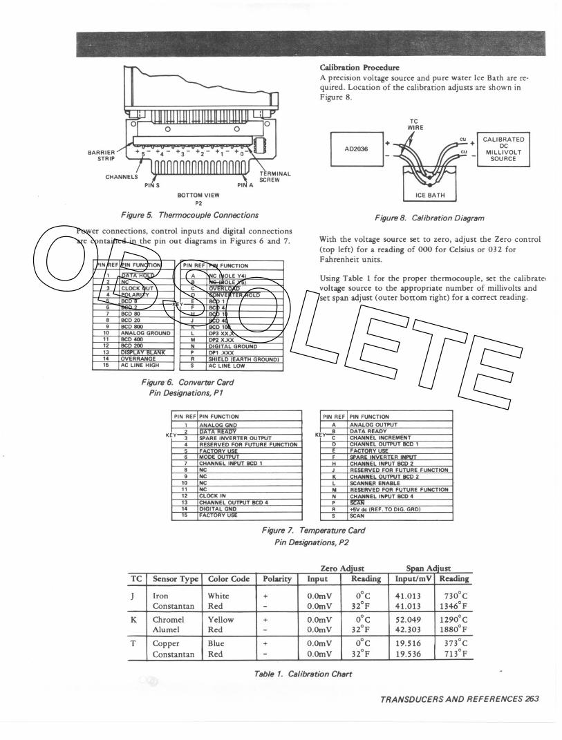
wOoingConnectionsPower connections, thermocouple connections and controland digital connections are accessible at the rear. All but thethermocouple connections are via card edge (see Figures 6 and7). Thermocouple wires are connected to a barrier strip on thetop board (see Figure 5).
To install thermocouple wires, remove shroud from rear ofunit by removing the screw. Feed thermocouple wiresthrough slots in the shroud (see Figure 9). Thermocouple "inp'wires are attached directly to the barrier strip. For easy acces:turn AD2036 upside down. (+) and (-) polarities are designateon the P.C.B. Care must be taken when connecting input wir,to insure correct polarity. Figure 5 shows proper polarity arvchannel designations. Replace shroud after connecting TC's.
OBSOLETE
BARRIERSTRIP
PIN A
BOTTOM VIEW
P2
Figure 5. Thermocouple Connections
Power connections, control inputs and digital connectionsare contained in the pin out diagrams in Figures 6 and 7.
E
Figure '6. Converter CardPin Designations, P 1
K
Calibration Procedure
A precision voltage source and pure water Ice Bath are re-quired. Location of the calibration adjusts are shown inFigure 8,
TCWIRE
B: + I CALIBRATEDDCMILLIVOLT
SOURCE
ICE BATH
Figure 8. Calibration Diagram
With the voltage source set to zero, adjust the Zero control(top left) for a reading of 000 for Celsius or 032 forFahrenheit units.
Using Table 1 for the proper thermocouple, set the calibrate.voltage source to the appropriate number of millivolts andset span adjust (outer bottom right) for a correct reading.
K
Figure 7. Temperature Card
Pin Designations, P2
d' d'
Table 1. Calibration Chart
----
TRANSDUCERS AND REFERENCES 263
PIN REF PIN FUNCTION
1 DATA HOLD2 IN3 CLOCK OUT4 POLARITY5 BCD 8 K,6 BCD 27 BCD SO8 BCD209 BCD 800
10 ANALOG GROUND11 BCD 40012 BCD 20013 DISPLAY BLANK14 OVERRANGE15 AC LINE HIGH
PIN REF PIN FUNCTION
ABC0 L
Y E BCD 1F BCD 4H BCD 10J BCD4DK BCD 100L DP3 XX.XM DP2 X.XXN DIGITAL GROUNDP DP1 .XXXR SHIELD EARTH GROUND}S AC LINE LOW
IPIN REF PIN FUNCTION
I 1 ANALOG GND
Y2 DATA READY3 SPARE INVERTER OUTPUT4 RESERVED FOR FUTURE FUNCTION5 FA6 MODE OUTPUT7 CHANNEL INPUT BCD 18 NC9 NC
10 NC11 NC12 CLOCK IN13 CHANNEL OUTPUT BCD 414 DIGITAL GND15 FACTORY USE
PIN REF PIN FUNCTIONI A ANALOG OUTPUT
E B DATA READYC CHANNEL INCREMENT0 CHANNEL OUTPUT BCD 1E FACTORY USEF SPARE INVERTER INPUTH CiiANNEL INPUT BCD 2J RESERVED FOR FUTURE FUNCTIONK I""ANNE' OUTPUT AN> 2L SCAN ENABLEM RESERVED FOR FUTURE FUNCTIONN CHANNEL INPUT BCD4P r!!l!DTR +5V de (REF. TO DIG. GRD)S SCAN
-u- n- _n - -- --- -n
TC Sensor Type Color Code Polarity Input Reading Input/mV Reading
J Iron White + O.Omv OoC 41.013 730°CConstantan Red - O.Omv noF 41.013 1346°F
K Chromel Yellow + O.OmV OoC 52.049 1290oCAlumel Red - O.OmV 32°F 42.03 1880oF
T Copper Blue + O.OmV OOC 19.516 373°CConstantan Red - O.Omv 3ZoF 19.536 713°F
OBSOLETE

14.18 1106.01
0000000A02038
POWER SUPPlY INPUT
- 0 '" VAC50.S0'" '0 100VAG50.60'"E 0 220 VAG 50.60 '" H 0 260 VA< 50-60 '"
THERMOCOUPLE SELECTION
J 0 .60 w 700"C .,. w 1400°'K 0 .SO '" '350°C .,. w 2000°'T 0100 0" 400°C,,", w T"o,
OEOREE READOUT, 0 DEGREE CENTIGRADE2 0 DEGREE 'AHRENHEfT
0 DENOTES OPTOON
00000000000000
"ANALOGWOEVICES
MADE IN U.SAVENTI LATlONHOLES
15
TOP VIEW
Lr 5.80 (147.31
0.93123.61
t'-
6.43 (163.31
KEY BETWEENPINS2&3CONNECTOR P2
SLOTS FORTHERMOCOUPLEWIRES
0.045 MAX
11.141
@ @
@@
3.92 199.61
KEY BETWEENPINS5&6CONNECTOR P1
REAR VIEW
ZERO ADJUST
IFACTORY USE) b
FRONT VIEW
0.3619.71
It
(FACTORYUSEI ,SPAN ADJUST
0400
~110.161
MAX-I
4.48 1113.BI
5.10 (129.51
02616.601
SIDE VIEW
Figure 9. AD2036 Mechanical Outline(Dimensions shown in inches and (mm))
c==::-BLOCK TENSIONSCREW
0'
PANEL THICKNESS0.0625 to 0.125(1.61 to 13.21
SHROUD
--,
MOUNTING INSTRUCTIONS,
1. SLIDE DPM THROUGH PANEL CUTOl'T FROM FRONT OF PANEL.2. SNAP MOUNTING BlOCK INTO SLOT ON DPM SIDES.3. TIGHTEN MOUNTING BLOCK TENSION SCREWS SNUGLY TO
SECURE DPM TO PANEL (DO NOT OVERTIGHTEN!)4. SNAP LENS ONTO FRONT OF DPM.
Figure 10. AD2036 Mounting Instructions(Dimensions shown in inches and (mm))
264 TRANSDUCERS AND REFERENCES
OBSOLETE