an5017 - nxp
TRANSCRIPT

AN5017 Aerospace Android and Windows Coordinate Systems Rev. 2.0 — 21 June 2016 Application note
Document information Info Content Abstract This application note documents the three coordinate systems
(Aerospace, Windows and Android) supported in the NXP Sensor Fusion Library.
NXP Semiconductors AN5017 Aerospace Android and Windows Coordinate Systems
AN5017 All information provided in this document is subject to legal disclaimers. © NXP B.V. 2016. All rights reserved.
Application note Rev. 2.0 — 21 June 2016 2 of 28
Contact information For more information, please visit: http://www.nxp.com
Revision history Document ID Release date Supercedes AN5017 v2.0 20160621 AN5017 v1.0
Modifications: • Minor changes • The format of this document has been redesigned to comply with the new identity guidelines of
NXP Semiconductors. Legal texts have been adapted to the new company name where appropriate.
AN5017 v1.0 9/2015 Initial release

NXP Semiconductors AN5017 Aerospace Android and Windows Coordinate Systems
AN5017 All information provided in this document is subject to legal disclaimers. © NXP B.V. 2016. All rights reserved.
Application note Rev. 2.0 — 21 June 2016 3 of 28
1. Introduction
1.1 Summary This application note documents the three coordinate systems supported in the NXP Sensor Fusion Library: • Aerospace (an x=North, y=East, z=Down or NED standard) • Android (an x=East, y=North, z=Up or ENU standard) • Windows 8 (also an x=East, y=North, z=Up or ENU standard)
When developing for Android or Windows 8 systems, the user should use the corresponding coordinate system. Otherwise, the Aerospace coordinate system is probably the best choice because its sequence of rotations and the ranges of its Euler angles result in a yaw/compass heading estimate that is more user friendly than that computed using the other two coordinate systems.
Specifically, a 180° roll in the Aerospace coordinate system does not change the yaw/compass heading while a 180° pitch rotation does change the yaw/compass heading by 180°. This matches the behavior of an aircraft where a 180° roll simply means that the aircraft is on the same compass heading but inverted and where a 180° change in pitch means that the aircraft is on the reverse compass heading and inverted. The opposite behavior is mandated for the Android and Windows 8 coordinate systems where a 180° roll introduces a 180° change in compass heading and where a 180° pitch rotation has no effect on compass heading.
1.2 Software Functions
Table 1. Sensor Fusion software functions Functions Description Reference
void fNEDAnglesDegFromRotationMatrix (float R[][3], float *pfPhiDeg, float *pfTheDeg, float *pfPsiDeg, float *pfRhoDeg, float *pfChiDeg); void fAndroidAnglesDegFromRotationMatrix (float R[][3], float *pfPhiDeg, float *pfTheDeg, float *pfPsiDeg, float *pfRhoDeg, float *pfChiDeg); void fWin8AnglesDegFromRotationMatrix (float R[][3], float *pfPhiDeg, float *pfTheDeg, float *pfPsiDeg, float *pfRhoDeg, float *pfChiDeg);
Compute the Euler angles (roll, pitch, yaw) plus compass heading and tilt angles from Aerospace/NED, Android and Windows 8 orientation matrices.
2 (NED) 3 (Android) 4 (Windows 8)

NXP Semiconductors AN5017 Aerospace Android and Windows Coordinate Systems
AN5017 All information provided in this document is subject to legal disclaimers. © NXP B.V. 2016. All rights reserved.
Application note Rev. 2.0 — 21 June 2016 4 of 28
1.3 Terminology Term/Symbol Definition
𝑞𝑞 General quaternion 𝑞𝑞 = (𝑞𝑞0, 𝑞𝑞1, 𝑞𝑞2, 𝑞𝑞3)
𝑹𝑹 Rotation matrix
𝑹𝑹𝑁𝑁𝑁𝑁𝑁𝑁 Aerospace (NED) rotation matrix
𝑹𝑹𝐴𝐴𝐴𝐴𝐴𝐴𝐴𝐴𝐴𝐴𝐴𝐴𝐴𝐴 Android rotation matrix
𝑹𝑹𝑊𝑊𝐴𝐴𝐴𝐴8 Windows 8 rotation matrix
𝑹𝑹𝑥𝑥 Rotation matrix about x-axis
𝑹𝑹𝑦𝑦 Rotation matrix about y-axis
𝑹𝑹𝑧𝑧 Rotation matrix about z-axis
𝜃𝜃 Pitch angle
ρ Compass heading angle
𝜙𝜙 Roll angle
𝜒𝜒 Tilt angle
ψ Yaw angle
1.4 Equivalency of Gravity and Acceleration Accelerometers measure linear acceleration minus the gravity component in each axis. This is a consequence of basic Physics which states the equivalence between the forces experienced when at rest in a gravitational field and when accelerating in the opposite direction to gravity.
For example, an observer sitting on a chair at rest on earth with a 1g downward-pointing gravitational field experiences exactly the same force as when sitting in a spaceship remote from any gravitational field accelerating at 1g in the opposite direction.
1.5 Differences in Coordinate Systems The Aerospace coordinate system defines the direction of axes in the zero rotation orientation as being x=North, y=East and z=Down (or NED). The Android and Windows 8 coordinate systems define the direction of axes in the same zero rotation orientation to be x=East, y=North, z=Up (or ENU).
An additional complication is that, whereas all accelerometers are natively acceleration positive in their outputs, the axes in the Aerospace and Windows 8 coordinate systems are specified to be gravity positive meaning that an axis measures +1g when pointed downward and aligned with gravity. The Android coordinate system is acceleration positive meaning that an axis measures +1g when pointed upwards and aligned with the equivalent 1g acceleration in the opposite direction to gravity.
The Aerospace and Windows 8 coordinate systems define rotations in the usual mathematical sense where a rotation is positive when it is clockwise when viewed in the increasing direction of an axis. Rotations in the Android coordinate system have the opposite sign.

NXP Semiconductors AN5017 Aerospace Android and Windows Coordinate Systems
AN5017 All information provided in this document is subject to legal disclaimers. © NXP B.V. 2016. All rights reserved.
Application note Rev. 2.0 — 21 June 2016 5 of 28
Table 2 summarizes these differences.
Table 2. Coordinate system comparison Item Aerospace (NED) Android (ENU) Windows 8 (ENU) Axes alignment XYZ = NED XYZ = ENU XYZ = ENU
Accelerometer sign Gravity-Acceleration +1g when axis is down –1g when axis is up
Acceleration-Gravity +1g when axis is up –1g when axis is down
Gravity-Acceleration +1g when axis is down –1g when axis is up
Accelerometer reading when flat
G[Z] = +1g G[Z] = +1g G[Z] = –1g
Direction of positive rotation
Clockwise Anticlockwise Clockwise
Compass heading ρ and yaw angle ψ
ρ = ψ ρ = ψ ρ = 360°–ψ
Refer to Section 2.1, 3.1 and 4.1 for definitions of the axes, the sign standard for the accelerometer and the definition of a positive rotation about any axis for the Aerospace, Android and Windows 8 coordinate systems.
1.6 Euler Angle Orientation Matrix Euler angles (roll, pitch and yaw angles) have very poor mathematical properties in comparison with rotation matrices and quaternions and should be avoided. Euler angles are only used in NXP's Sensor Fusion Library software as an output for human use since they are intuitively understandable.
One of the Euler angles’ mathematical problems is that rotation matrices do not commute meaning that the order in which individual Euler angle rotations are applied is important. The same three Euler angles will give different rotation matrices when applied in different sequence. Simply specifying the roll, pitch and yaw Euler angles without specifying their sequence is meaningless.
Another problem is that Euler angles have discontinuities at certain orientations whereas a rotation matrix or rotation quaternion is always continuous and varies smoothly with rotation. Finally, at orientations termed 'gimbal lock' the Euler angles become ambiguous and oscillate even though the rotation matrix and quaternion are stable.
Since the three coordinate standards do require that Euler angles be computed, table 2 below lists the decomposition of the orientation matrix into three Euler angle rotations.
Table 3. Sequence of Euler angle rotations Item Aerospace (NED) Android (ENU) Windows 8 (ENU)
Sequence of Euler angle rotations
𝑹𝑹 = 𝑹𝑹𝑥𝑥(𝜙𝜙)𝑹𝑹𝑦𝑦(𝜃𝜃)𝑹𝑹𝑧𝑧(𝜓𝜓) 𝑹𝑹 = 𝑹𝑹𝑥𝑥(𝜃𝜃)𝑹𝑹𝑦𝑦(𝜙𝜙)𝑹𝑹𝑧𝑧(𝜓𝜓) 𝑹𝑹 = 𝑹𝑹𝑦𝑦(𝜙𝜙)𝑹𝑹𝑥𝑥(𝜃𝜃)𝑹𝑹𝑧𝑧(𝜓𝜓)
1.7 Gimbal Lock Gimbal lock occurs in all three coordinate systems when the second rotation (pitch in Aerospace and Windows 8 systems and roll in the Android system) aligns the axes of the first and third Euler angle rotations. The number of degrees of freedom needed to define

NXP Semiconductors AN5017 Aerospace Android and Windows Coordinate Systems
AN5017 All information provided in this document is subject to legal disclaimers. © NXP B.V. 2016. All rights reserved.
Application note Rev. 2.0 — 21 June 2016 6 of 28
the orientation reduces from three Euler angles to two. Any change in the first Euler rotation angle can be offset by a cancelling change in the third Euler rotation angle with the result that the two values oscillate unstably together.
Gimbal lock in strapdown navigation systems is, therefore, a mathematical instability that results from the decomposition of the orientation matrix or quaternion into three individual Euler angle rotations and is easily avoided by using orientation matrix or quaternion representations which are completely stable at gimbal lock orientations.
The NXP Sensor Fusion Library uses orientation matrix and quaternion algebra throughout and computes Euler angles for human use as an output from the algorithms. The computed orientation is therefore just as stable at gimbal lock orientations as at other orientations. Any software fundamentally based on Euler angle rotations in preference to rotation matrix or quaternion will suffer from gimbal lock instability and mathematical discontinuities. Item Aerospace (NED) Android (ENU) Windows 8 (ENU) Gimbal Lock ±90° pitch (y-axis) ±90° roll (y-axis) ±90° pitch (x-axis)
Table 4. Gimbal lock defined by coordinate system
1.8 Euler Angle Discontinuities Another problem with Euler angles representation of orientation is that, in addition to there being an infinite number of Euler angle solutions at gimbal lock orientations, there are, in general, two Euler angle solutions for every orientation. This forces one of the Euler angles to be constrained with a reduced range of –90° to +90° to eliminate one of the two solutions.
The presence of two solutions is easily demonstrated with the starting position of the device laid flat on the table and then applying these two rotation sequences: • rotation of 180° in pitch • rotation of 180° in yaw followed by a rotation of 180° in pitch
Both rotation sequences result in the same physical orientation and the same orientation matrix and quaternion.
The Aerospace coordinate system restricts the range of the pitch angle from –90° to +90° and the Android and Windows 8 coordinate systems restrict the range of roll angle from –90°to +90°. Although this restriction results in just one Euler angle solution at all orientations except at gimbal lock, it creates the unfortunate mathematical side effect of introducing discontinuities in the Euler angles.
The table below summarizes the Euler angle discontinuities in each coordinate system. Sections 2 through 4 present more information on the meanings of the various table entries. Item Aerospace (NED) Android (ENU) Windows 8 (ENU) Ranges of Euler angles
0° ≤ Yaw ψ (z) < 360°
–90° ≤ Pitch θ (y) < 90°
–180° ≤ Roll φ (x) < 180°
0° ≤ Yaw ψ (z) < 360°
–90° ≤ Roll φ (y) < 90°
–180° ≤ Pitch θ (x) < 180°
0° ≤ Yaw ψ (z) < 360°
–180° ≤ Pitch θ (x) < 180°
–90° ≤ Roll φ (y) < 90°
Equivalent matrix
𝑹𝑹𝑥𝑥(𝜙𝜙 + 𝜋𝜋)𝑹𝑹𝑦𝑦(𝜋𝜋 − 𝜃𝜃)𝑹𝑹𝑧𝑧(𝜓𝜓+ 𝜋𝜋)
𝑹𝑹𝑥𝑥(𝜃𝜃 + 𝜋𝜋)𝑹𝑹𝑦𝑦(𝜋𝜋 − 𝜙𝜙)𝑹𝑹𝑧𝑧(𝜓𝜓+ 𝜋𝜋)
𝑹𝑹𝑦𝑦(𝜙𝜙 − 𝜋𝜋)𝑹𝑹𝑥𝑥(𝜋𝜋 − 𝜃𝜃)𝑹𝑹𝑧𝑧(𝜓𝜓+ 𝜋𝜋)

NXP Semiconductors AN5017 Aerospace Android and Windows Coordinate Systems
AN5017 All information provided in this document is subject to legal disclaimers. © NXP B.V. 2016. All rights reserved.
Application note Rev. 2.0 — 21 June 2016 7 of 28
Item Aerospace (NED) Android (ENU) Windows 8 (ENU) Behavior during ±180 degree roll rotation
Roll is continuous in range –180° to 180°.
No change in yaw or compass angle.
Roll is continuous, increasing to 90° and then decreasing or decreasing to –90° and then increasing.
Pitch and yaw have 180° discontinuities at ±90° roll.
180° jump in roll, pitch, yaw and compass as the roll angle passes 90° and –90°.
Behavior during ±180 degree pitch rotation
Pitch is continuous, increasing to 90° and then decreasing or decreasing to –90° and then increasing.
Roll and yaw have 180° discontinuity at ±90° pitch.
Smooth changes in pitch. No change in roll, yaw or compass.
Smooth changes in pitch. No change in roll, yaw or compass.
2. Aerospace (NED) Coordinate System
2.1 Axes Definitions The Aerospace coordinate system is shown in Fig 1. It is an x=North, y=East, z=Down (termed NED) coordinate system, meaning that when the product is positioned in its default orientation, flat on the table and pointed northward, the x-axis points north, the y-axis points east and the z-axis points down.
The sign of rotations about the x, y and z axes is defined in the normal convention as a clockwise rotation and is deemed positive when looking along the increasing direction of the axis. Roll, pitch and yaw rotations have their normal meaning and correspond to rotations about the x, y and z axes, respectively. The yaw angle ψ equals the compass angle ρ.
The Aerospace coordinate system is gravity (not acceleration) positive, meaning that the output of any accelerometer channel is positive when pointing downward and aligned with gravity. The accelerometer z-axis reading is therefore +1 g when the device is flat and upright.

NXP Semiconductors AN5017 Aerospace Android and Windows Coordinate Systems
AN5017 All information provided in this document is subject to legal disclaimers. © NXP B.V. 2016. All rights reserved.
Application note Rev. 2.0 — 21 June 2016 8 of 28
Fig 1. Aerospace (NED) coordinate system
2.2 Orientation Matrix in Terms of Euler Angles The sequence of Euler angle rotations in the Aerospace coordinate system is yaw followed by pitch and finally roll. The roll rotation ϕ is about the x-axis, the pitch rotation θ about the y-axis and the yaw rotation ψ about the z-axis. The individual rotation matrices are:
𝑹𝑹𝑥𝑥(𝜙𝜙) = �1 0 00 𝑐𝑐𝑐𝑐𝑐𝑐 𝜙𝜙 𝑐𝑐𝑠𝑠𝑠𝑠𝜙𝜙0 −𝑐𝑐𝑠𝑠𝑠𝑠𝜙𝜙 𝑐𝑐𝑐𝑐𝑐𝑐𝜙𝜙
� (1)
𝑹𝑹𝑦𝑦(𝜃𝜃) = �𝑐𝑐𝑐𝑐𝑐𝑐 𝜃𝜃 0 −𝑐𝑐𝑠𝑠𝑠𝑠𝜃𝜃
0 1 0𝑐𝑐𝑠𝑠𝑠𝑠𝜃𝜃 0 𝑐𝑐𝑐𝑐𝑐𝑐𝜃𝜃
� (2)
𝑹𝑹𝑧𝑧(𝜓𝜓) = �𝑐𝑐𝑐𝑐𝑐𝑐 𝜓𝜓 𝑐𝑐𝑠𝑠𝑠𝑠𝜓𝜓 0−𝑐𝑐𝑠𝑠𝑠𝑠𝜓𝜓 𝑐𝑐𝑐𝑐𝑐𝑐 𝜓𝜓 0
0 0 1� (3)
The composite Aerospace rotation matrix using the specified rotation sequence is:
𝑹𝑹𝑁𝑁𝑁𝑁𝑁𝑁 = 𝑹𝑹𝑥𝑥(𝜙𝜙)𝑹𝑹𝑦𝑦(𝜃𝜃)𝑹𝑹𝑧𝑧(𝜓𝜓)
= �1 0 00 𝑐𝑐𝑐𝑐𝑐𝑐 𝜙𝜙 𝑐𝑐𝑠𝑠𝑠𝑠𝜙𝜙0 −𝑐𝑐𝑠𝑠𝑠𝑠𝜙𝜙 𝑐𝑐𝑐𝑐𝑐𝑐𝜙𝜙
��𝑐𝑐𝑐𝑐𝑐𝑐 𝜃𝜃 0 −𝑐𝑐𝑠𝑠𝑠𝑠𝜃𝜃
0 1 0𝑐𝑐𝑠𝑠𝑠𝑠𝜃𝜃 0 𝑐𝑐𝑐𝑐𝑐𝑐𝜃𝜃
��−𝑐𝑐𝑐𝑐𝑐𝑐 𝜓𝜓 𝑐𝑐𝑠𝑠𝑠𝑠𝜓𝜓 0𝑐𝑐𝑠𝑠𝑠𝑠𝜓𝜓 𝑐𝑐𝑐𝑐𝑐𝑐 𝜓𝜓 0
0 0 1�
(4)
⇒ 𝑹𝑹𝑁𝑁𝑁𝑁𝑁𝑁
= �𝑐𝑐𝑐𝑐𝑐𝑐 𝜃𝜃 𝑐𝑐𝑐𝑐𝑐𝑐 𝜓𝜓 𝑐𝑐𝑐𝑐𝑐𝑐 𝜃𝜃 𝑐𝑐𝑠𝑠𝑠𝑠𝜓𝜓 −𝑐𝑐𝑠𝑠𝑠𝑠𝜃𝜃
𝑐𝑐𝑐𝑐𝑐𝑐 𝜓𝜓 𝑐𝑐𝑠𝑠𝑠𝑠𝜃𝜃𝑐𝑐𝑠𝑠𝑠𝑠𝜙𝜙 − 𝑐𝑐𝑐𝑐𝑐𝑐 𝜙𝜙 𝑐𝑐𝑠𝑠𝑠𝑠𝜓𝜓 𝑐𝑐𝑐𝑐𝑐𝑐 𝜙𝜙 𝑐𝑐𝑐𝑐𝑐𝑐 𝜓𝜓 + 𝑐𝑐𝑠𝑠𝑠𝑠𝜃𝜃𝑐𝑐𝑠𝑠𝑠𝑠𝜙𝜙𝑐𝑐𝑠𝑠𝑠𝑠𝜓𝜓 𝑐𝑐𝑐𝑐𝑐𝑐 𝜃𝜃 𝑐𝑐𝑠𝑠𝑠𝑠𝜙𝜙𝑐𝑐𝑐𝑐𝑐𝑐𝜙𝜙 𝑐𝑐𝑐𝑐𝑐𝑐 𝜓𝜓 𝑐𝑐𝑠𝑠𝑠𝑠𝜃𝜃 + 𝑐𝑐𝑠𝑠𝑠𝑠𝜙𝜙𝑐𝑐𝑠𝑠𝑠𝑠𝜓𝜓 𝑐𝑐𝑐𝑐𝑐𝑐 𝜙𝜙 𝑐𝑐𝑠𝑠𝑠𝑠𝜃𝜃𝑐𝑐𝑠𝑠𝑠𝑠𝜓𝜓 − 𝑐𝑐𝑐𝑐𝑐𝑐 𝜓𝜓 𝑐𝑐𝑠𝑠𝑠𝑠𝜙𝜙 𝑐𝑐𝑐𝑐𝑐𝑐 𝜃𝜃 𝑐𝑐𝑐𝑐𝑐𝑐𝜙𝜙
� (5)
N, x
E, y
D, z
Compass Pointing Direction
Roll φ
Yaw ψ Pitch θ

NXP Semiconductors AN5017 Aerospace Android and Windows Coordinate Systems
AN5017 All information provided in this document is subject to legal disclaimers. © NXP B.V. 2016. All rights reserved.
Application note Rev. 2.0 — 21 June 2016 9 of 28
2.3 Orientation Quaternion in Terms of Euler Angles The individual Euler angle rotation quaternions in the Aerospace coordinate system are:
𝑞𝑞𝑥𝑥(𝜙𝜙) = 𝑐𝑐𝑐𝑐𝑐𝑐 �𝜙𝜙2� + 𝒊𝒊𝑐𝑐𝑠𝑠𝑠𝑠 �
𝜙𝜙2� (6)
𝑞𝑞𝑦𝑦(𝜃𝜃) = 𝑐𝑐𝑐𝑐𝑐𝑐 �𝜃𝜃2� + 𝒋𝒋𝑐𝑐𝑠𝑠𝑠𝑠 �
𝜃𝜃2� (7)
𝑞𝑞𝑧𝑧(𝜓𝜓) = 𝑐𝑐𝑐𝑐𝑐𝑐 �𝜓𝜓2� + 𝒌𝒌𝑐𝑐𝑠𝑠𝑠𝑠 �
𝜓𝜓2� (8)
The Aerospace rotation quaternion 𝑞𝑞𝑧𝑧𝑦𝑦𝑥𝑥 = 𝑞𝑞𝑧𝑧(𝜓𝜓)𝑞𝑞𝑦𝑦(𝜃𝜃)𝑞𝑞𝑥𝑥(𝜙𝜙) evaluates to:
𝑞𝑞𝑧𝑧𝑦𝑦𝑥𝑥 = 𝑞𝑞𝑧𝑧(𝜓𝜓)𝑞𝑞𝑦𝑦(𝜃𝜃)𝑞𝑞𝑥𝑥(𝜙𝜙) = �𝑐𝑐𝑐𝑐𝑐𝑐 �𝜓𝜓2� + 𝒌𝒌𝑐𝑐𝑠𝑠𝑠𝑠 �
𝜓𝜓2�� �𝑐𝑐𝑐𝑐𝑐𝑐 �
𝜃𝜃2�+ 𝒋𝒋𝑐𝑐𝑠𝑠𝑠𝑠 �
𝜃𝜃2�� �𝑐𝑐𝑐𝑐𝑐𝑐 �
𝜙𝜙2� + 𝒊𝒊𝑐𝑐𝑠𝑠𝑠𝑠 �
𝜙𝜙2�� (9)
= �𝑐𝑐𝑐𝑐𝑐𝑐 �𝜓𝜓2� 𝑐𝑐𝑐𝑐𝑐𝑐 �
𝜃𝜃2� 𝑐𝑐𝑐𝑐𝑐𝑐 �
𝜙𝜙2� + 𝑐𝑐𝑠𝑠𝑠𝑠 �
𝜓𝜓2� 𝑐𝑐𝑠𝑠𝑠𝑠 �
𝜃𝜃2� 𝑐𝑐𝑠𝑠𝑠𝑠 �
𝜙𝜙2��
+ �𝑐𝑐𝑐𝑐𝑐𝑐 �𝜓𝜓2� 𝑐𝑐𝑐𝑐𝑐𝑐 �
𝜃𝜃2� 𝑐𝑐𝑠𝑠𝑠𝑠 �
𝜙𝜙2� − 𝑐𝑐𝑠𝑠𝑠𝑠 �
𝜓𝜓2� 𝑐𝑐𝑠𝑠𝑠𝑠 �
𝜃𝜃2� 𝑐𝑐𝑐𝑐𝑐𝑐 �
𝜙𝜙2�� 𝒊𝒊
+ �𝑐𝑐𝑐𝑐𝑐𝑐 �𝜓𝜓2� 𝑐𝑐𝑠𝑠𝑠𝑠 �
𝜃𝜃2� 𝑐𝑐𝑐𝑐𝑐𝑐 �
𝜙𝜙2� + 𝑐𝑐𝑠𝑠𝑠𝑠 �
𝜓𝜓2� 𝑐𝑐𝑐𝑐𝑐𝑐 �
𝜃𝜃2� 𝑐𝑐𝑠𝑠𝑠𝑠 �
𝜙𝜙2�� 𝒋𝒋
+ �𝑐𝑐𝑠𝑠𝑠𝑠 �𝜓𝜓2� 𝑐𝑐𝑐𝑐𝑐𝑐 �
𝜃𝜃2� 𝑐𝑐𝑐𝑐𝑐𝑐 �
𝜙𝜙2� − 𝑐𝑐𝑐𝑐𝑐𝑐 �
𝜓𝜓2� 𝑐𝑐𝑠𝑠𝑠𝑠 �
𝜃𝜃2� 𝑐𝑐𝑠𝑠𝑠𝑠 �
𝜙𝜙2�� 𝒌𝒌
(10)
The elements of the Aerospace quaternion 𝑞𝑞𝑧𝑧𝑦𝑦𝑥𝑥 are, therefore:
𝑞𝑞0 = 𝑐𝑐𝑐𝑐𝑐𝑐 �𝜓𝜓2� 𝑐𝑐𝑐𝑐𝑐𝑐 �
𝜃𝜃2� 𝑐𝑐𝑐𝑐𝑐𝑐 �
𝜙𝜙2� + 𝑐𝑐𝑠𝑠𝑠𝑠 �
𝜓𝜓2� 𝑐𝑐𝑠𝑠𝑠𝑠 �
𝜃𝜃2� 𝑐𝑐𝑠𝑠𝑠𝑠 �
𝜙𝜙2� (11)
𝑞𝑞1 = 𝑐𝑐𝑐𝑐𝑐𝑐 �𝜓𝜓2� 𝑐𝑐𝑐𝑐𝑐𝑐 �
𝜃𝜃2� 𝑐𝑐𝑠𝑠𝑠𝑠 �
𝜙𝜙2� − 𝑐𝑐𝑠𝑠𝑠𝑠 �
𝜓𝜓2� 𝑐𝑐𝑠𝑠𝑠𝑠 �
𝜃𝜃2� 𝑐𝑐𝑐𝑐𝑐𝑐 �
𝜙𝜙2� (12)
𝑞𝑞2 = 𝑐𝑐𝑐𝑐𝑐𝑐 �𝜓𝜓2� 𝑐𝑐𝑠𝑠𝑠𝑠 �
𝜃𝜃2� 𝑐𝑐𝑐𝑐𝑐𝑐 �
𝜙𝜙2� + 𝑐𝑐𝑠𝑠𝑠𝑠 �
𝜓𝜓2� 𝑐𝑐𝑐𝑐𝑐𝑐 �
𝜃𝜃2� 𝑐𝑐𝑠𝑠𝑠𝑠 �
𝜙𝜙2� (13)
𝑞𝑞3 = 𝑐𝑐𝑠𝑠𝑠𝑠 �𝜓𝜓2� 𝑐𝑐𝑐𝑐𝑐𝑐 �
𝜃𝜃2� 𝑐𝑐𝑐𝑐𝑐𝑐 �
𝜙𝜙2� − 𝑐𝑐𝑐𝑐𝑐𝑐 �
𝜓𝜓2� 𝑐𝑐𝑠𝑠𝑠𝑠 �
𝜃𝜃2� 𝑐𝑐𝑠𝑠𝑠𝑠 �
𝜙𝜙2� (14)
2.4 Gimbal Lock Gimbal lock occurs in the Aerospace coordinate system when the second pitch rotation aligns the first yaw and third roll rotations. This occurs at 90° pitch upward and 90° pitch downward. The number of degrees of freedom in the Euler angle description of the orientation reduces from three to two and the roll and yaw angles oscillate with only their sum and difference defined.

NXP Semiconductors AN5017 Aerospace Android and Windows Coordinate Systems
AN5017 All information provided in this document is subject to legal disclaimers. © NXP B.V. 2016. All rights reserved.
Application note Rev. 2.0 — 21 June 2016 10 of 28
At gimbal lock 𝜃𝜃 = 90𝑑𝑑𝑑𝑑𝑑𝑑 and 𝜃𝜃 = −90𝑑𝑑𝑑𝑑𝑑𝑑, equation (5) simplifies to:
𝑹𝑹𝑁𝑁𝑁𝑁𝑁𝑁 = �0 0 −1
−𝑐𝑐𝑠𝑠𝑠𝑠(𝜓𝜓 − 𝜙𝜙) 𝑐𝑐𝑐𝑐𝑐𝑐(𝜓𝜓 − 𝜙𝜙) 0𝑐𝑐𝑐𝑐𝑐𝑐(𝜓𝜓 − 𝜙𝜙) 𝑐𝑐𝑠𝑠𝑠𝑠(𝜓𝜓 − 𝜙𝜙) 0
� 𝑓𝑓𝑐𝑐𝑓𝑓 𝜃𝜃 = 90𝑑𝑑𝑑𝑑𝑑𝑑 (15)
𝑹𝑹𝑁𝑁𝑁𝑁𝑁𝑁 = �0 0 1
−𝑐𝑐𝑠𝑠𝑠𝑠(𝜓𝜓 + 𝜙𝜙) 𝑐𝑐𝑐𝑐𝑐𝑐(𝜓𝜓 + 𝜙𝜙) 0−𝑐𝑐𝑐𝑐𝑐𝑐(𝜓𝜓 + 𝜙𝜙) −𝑐𝑐𝑠𝑠𝑠𝑠(𝜓𝜓 + 𝜙𝜙) 0
� 𝑓𝑓𝑐𝑐𝑓𝑓 𝜃𝜃 = −90𝑑𝑑𝑑𝑑𝑑𝑑 (16)
The orientation matrix and quaternion are stable but only the differenced angle 𝜓𝜓 − 𝜙𝜙 or the summed angle 𝜓𝜓 + 𝜙𝜙 can be determined at the two gimbal lock orientations.
2.5 Euler Angle Discontinuities The Aerospace rotation matrix 𝑹𝑹𝑥𝑥(𝜙𝜙)𝑹𝑹𝑦𝑦(𝜃𝜃)𝑹𝑹𝑧𝑧(𝜓𝜓) is equal to the matrix 𝑹𝑹𝑥𝑥(𝜙𝜙 + 𝜋𝜋)𝑹𝑹𝑦𝑦(𝜋𝜋 − 𝜃𝜃)𝑹𝑹𝑧𝑧(𝜓𝜓 + 𝜋𝜋), where 𝜋𝜋 radians correspond to 180°. By direct evaluation:
𝑹𝑹𝑥𝑥(𝜙𝜙 + 𝜋𝜋)𝑹𝑹𝑦𝑦(𝜋𝜋 − 𝜃𝜃)𝑹𝑹𝑧𝑧(𝜓𝜓 + 𝜋𝜋)
= �−𝑐𝑐𝑐𝑐𝑐𝑐(𝜋𝜋 − 𝜃𝜃) 𝑐𝑐𝑐𝑐𝑐𝑐 𝜓𝜓 −𝑐𝑐𝑐𝑐𝑐𝑐(𝜋𝜋 − 𝜃𝜃) 𝑐𝑐𝑠𝑠𝑠𝑠𝜓𝜓 −𝑐𝑐𝑠𝑠𝑠𝑠(𝜋𝜋 − 𝜃𝜃)
𝑐𝑐𝑐𝑐𝑐𝑐 𝜓𝜓 𝑐𝑐𝑠𝑠𝑠𝑠(𝜋𝜋 − 𝜃𝜃)𝑐𝑐𝑠𝑠𝑠𝑠𝜙𝜙 − 𝑐𝑐𝑐𝑐𝑐𝑐𝜙𝜙 𝑐𝑐𝑠𝑠𝑠𝑠𝜓𝜓 𝑐𝑐𝑐𝑐𝑐𝑐 𝜙𝜙 𝑐𝑐𝑐𝑐𝑐𝑐𝜓𝜓 + 𝑐𝑐𝑠𝑠𝑠𝑠(𝜋𝜋 − 𝜃𝜃)𝑐𝑐𝑠𝑠𝑠𝑠𝜙𝜙𝑐𝑐𝑠𝑠𝑠𝑠𝜓𝜓 −𝑐𝑐𝑐𝑐𝑐𝑐(𝜋𝜋 − 𝜃𝜃) 𝑐𝑐𝑠𝑠𝑠𝑠𝜙𝜙𝑐𝑐𝑐𝑐𝑐𝑐𝜙𝜙 𝑐𝑐𝑐𝑐𝑐𝑐𝜓𝜓 𝑐𝑐𝑠𝑠𝑠𝑠(𝜋𝜋 − 𝜃𝜃) + 𝑐𝑐𝑠𝑠𝑠𝑠𝜙𝜙𝑐𝑐𝑠𝑠𝑠𝑠𝜓𝜓 𝑐𝑐𝑐𝑐𝑐𝑐𝜙𝜙 𝑐𝑐𝑠𝑠𝑠𝑠(𝜋𝜋 − 𝜃𝜃)𝑐𝑐𝑠𝑠𝑠𝑠𝜓𝜓 − 𝑐𝑐𝑐𝑐𝑐𝑐𝜓𝜓 𝑐𝑐𝑠𝑠𝑠𝑠𝜙𝜙 −𝑐𝑐𝑐𝑐𝑐𝑐(𝜋𝜋 − 𝜃𝜃) 𝑐𝑐𝑐𝑐𝑐𝑐𝜙𝜙
� (17)
= �𝑐𝑐𝑐𝑐𝑐𝑐 𝜃𝜃 𝑐𝑐𝑐𝑐𝑐𝑐 𝜓𝜓 𝑐𝑐𝑐𝑐𝑐𝑐 𝜃𝜃 𝑐𝑐𝑠𝑠𝑠𝑠𝜓𝜓 −𝑐𝑐𝑠𝑠𝑠𝑠𝜃𝜃
𝑐𝑐𝑐𝑐𝑐𝑐𝜓𝜓 𝑐𝑐𝑠𝑠𝑠𝑠𝜃𝜃𝑐𝑐𝑠𝑠𝑠𝑠𝜙𝜙 − 𝑐𝑐𝑐𝑐𝑐𝑐𝜙𝜙 𝑐𝑐𝑠𝑠𝑠𝑠𝜓𝜓 𝑐𝑐𝑐𝑐𝑐𝑐 𝜙𝜙 𝑐𝑐𝑐𝑐𝑐𝑐𝜓𝜓 + 𝑐𝑐𝑠𝑠𝑠𝑠𝜃𝜃𝑐𝑐𝑠𝑠𝑠𝑠𝜙𝜙𝑐𝑐𝑠𝑠𝑠𝑠𝜓𝜓 𝑐𝑐𝑐𝑐𝑐𝑐 𝜃𝜃 𝑐𝑐𝑠𝑠𝑠𝑠𝜙𝜙𝑐𝑐𝑐𝑐𝑐𝑐𝜙𝜙 𝑐𝑐𝑐𝑐𝑐𝑐𝜓𝜓 𝑐𝑐𝑠𝑠𝑠𝑠𝜃𝜃 + 𝑐𝑐𝑠𝑠𝑠𝑠𝜙𝜙𝑐𝑐𝑠𝑠𝑠𝑠𝜓𝜓 𝑐𝑐𝑐𝑐𝑐𝑐𝜙𝜙 𝑐𝑐𝑠𝑠𝑠𝑠𝜃𝜃𝑐𝑐𝑠𝑠𝑠𝑠𝜓𝜓 − 𝑐𝑐𝑐𝑐𝑐𝑐𝜓𝜓 𝑐𝑐𝑠𝑠𝑠𝑠𝜙𝜙 𝑐𝑐𝑐𝑐𝑐𝑐 𝜃𝜃 𝑐𝑐𝑐𝑐𝑐𝑐𝜙𝜙
� = 𝑹𝑹𝑥𝑥(𝜙𝜙)𝑹𝑹𝑦𝑦(𝜃𝜃)𝑹𝑹𝑧𝑧(𝜓𝜓) (18)
This is the mathematical identity equivalent to the statement made in Section 1.8 that there are two Euler angle solutions to each orientation. This statement can be reworded as: An alternative to a rotation of 𝜓𝜓 in yaw then 𝜃𝜃 in pitch and finally by 𝜙𝜙 in roll, one can arrive at the same orientation by rotating 180° plus 𝜓𝜓 in yaw, then 180° minus 𝜃𝜃 in pitch and finally by 180° plus 𝜙𝜙 in roll.
The Aerospace coordinate system removes one of the two solutions by restricting the pitch angle 𝜃𝜃 to the range –90° to +90°. Equations (17) and (18) state that whenever the pitch angle is above 90° or less than –90° the roll angle should increase by 180° (the 𝑹𝑹𝑥𝑥(𝜙𝜙 + 𝜋𝜋) term), the pitch angle should be negated and 180° added (the 𝑹𝑹𝑦𝑦(𝜋𝜋– 𝜃𝜃) term) and the yaw/compass heading increased by 180° (the 𝑹𝑹𝑧𝑧(𝜓𝜓 + 𝜋𝜋) term). These discontinuities are shown in Fig 2 through Fig 4.
Fig 2 shows the Euler angles as the device is rotated through 360° in roll from the default starting position of being flat and pointed northward. Neither the pitch nor yaw angles change and the roll discontinuity from –180° to +180° is a consequence of modulo 360° arithmetic and is quite acceptable. The average user of an e-compass will agree that if a smartphone is pointed north and then given a roll rotation of 180°, then it is still pointed north.

NXP Semiconductors AN5017 Aerospace Android and Windows Coordinate Systems
AN5017 All information provided in this document is subject to legal disclaimers. © NXP B.V. 2016. All rights reserved.
Application note Rev. 2.0 — 21 June 2016 11 of 28
Fig 2. 360° roll rotation at zero pitch and yaw in the NED coordinate system
Fig 3 shows the Euler angles as the PCB is rotated 360° in pitch from the same starting position. The pitch angle reaches 90° and then starts smoothly decreasing without a discontinuity until it reaches –90° and then starts increasing smoothly. The yaw/compass angle flips by 180° at the 90° and –90° pitch angles, but this is reasonable ergonomic behavior. For the same reasons discussed above, the average smartphone user will consider a 180° pitch rotation to flip the yaw/compass heading 180°.
Fig 3. 360° pitch rotation at zero roll and yaw in the NED coordinate system
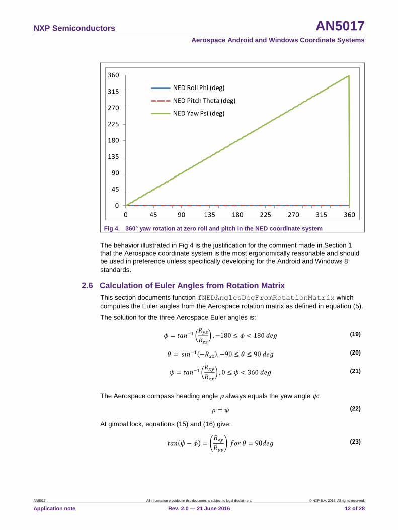
Fig 4 shows the yaw/compass angle behavior as the PCB is rotated 360° in yaw while remaining flat. The yaw/compass heading increases smoothly with the acceptable modulo 360° discontinuity when pointed northward.
-180
-135
-90
-45
0
45
90
135
180
0 45 90 135 180 225 270 315 360
NED Roll Phi (deg)
NED Pitch Theta (deg)
NED Yaw Psi (deg)
-180
-135
-90
-45
0
45
90
135
180
0 45 90 135 180 225 270 315 360
NED Roll Phi (deg)
NED Pitch Theta (deg)
NED Yaw Psi (deg)
NXP Semiconductors AN5017 Aerospace Android and Windows Coordinate Systems
AN5017 All information provided in this document is subject to legal disclaimers. © NXP B.V. 2016. All rights reserved.
Application note Rev. 2.0 — 21 June 2016 12 of 28
Fig 4. 360° yaw rotation at zero roll and pitch in the NED coordinate system
The behavior illustrated in Fig 4 is the justification for the comment made in Section 1 that the Aerospace coordinate system is the most ergonomically reasonable and should be used in preference unless specifically developing for the Android and Windows 8 standards.
2.6 Calculation of Euler Angles from Rotation Matrix This section documents function fNEDAnglesDegFromRotationMatrix which computes the Euler angles from the Aerospace rotation matrix as defined in equation (5).
The solution for the three Aerospace Euler angles is:
𝜙𝜙 = 𝑡𝑡𝑡𝑡𝑠𝑠−1 �𝑅𝑅𝑦𝑦𝑧𝑧𝑅𝑅𝑧𝑧𝑧𝑧
� ,−180 ≤ 𝜙𝜙 < 180 𝑑𝑑𝑑𝑑𝑑𝑑 (19)
𝜃𝜃 = 𝑐𝑐𝑠𝑠𝑠𝑠−1(−𝑅𝑅𝑥𝑥𝑧𝑧),−90 ≤ 𝜃𝜃 ≤ 90 𝑑𝑑𝑑𝑑𝑑𝑑 (20)
𝜓𝜓 = 𝑡𝑡𝑡𝑡𝑠𝑠−1 �𝑅𝑅𝑥𝑥𝑦𝑦𝑅𝑅𝑥𝑥𝑥𝑥
� , 0 ≤ 𝜓𝜓 < 360 𝑑𝑑𝑑𝑑𝑑𝑑 (21)
The Aerospace compass heading angle ρ always equals the yaw angle ψ:
𝜌𝜌 = 𝜓𝜓 (22)
At gimbal lock, equations (15) and (16) give:
𝑡𝑡𝑡𝑡𝑠𝑠(𝜓𝜓 − 𝜙𝜙) = �𝑅𝑅𝑧𝑧𝑦𝑦𝑅𝑅𝑦𝑦𝑦𝑦
� 𝑓𝑓𝑐𝑐𝑓𝑓 𝜃𝜃 = 90𝑑𝑑𝑑𝑑𝑑𝑑 (23)
0
45
90
135
180
225
270
315
360
0 45 90 135 180 225 270 315 360
NED Roll Phi (deg)
NED Pitch Theta (deg)
NED Yaw Psi (deg)
NXP Semiconductors AN5017 Aerospace Android and Windows Coordinate Systems
AN5017 All information provided in this document is subject to legal disclaimers. © NXP B.V. 2016. All rights reserved.
Application note Rev. 2.0 — 21 June 2016 13 of 28
𝑡𝑡𝑡𝑡𝑠𝑠(𝜓𝜓 + 𝜙𝜙) = �−𝑅𝑅𝑧𝑧𝑦𝑦𝑅𝑅𝑦𝑦𝑦𝑦
� 𝑓𝑓𝑐𝑐𝑓𝑓 𝜃𝜃 = −90𝑑𝑑𝑑𝑑𝑑𝑑 (24)
The tilt angle from vertical χ can be determined from the scalar product of the rotated gravity vector and the downwards z-axis, giving:
𝑐𝑐𝑐𝑐𝑐𝑐𝜒𝜒 = �𝑹𝑹𝑁𝑁𝑁𝑁𝑁𝑁 �001�� ∙ �
001� = �
𝑅𝑅𝑥𝑥𝑧𝑧𝑅𝑅𝑦𝑦𝑧𝑧𝑅𝑅𝑧𝑧𝑧𝑧
� ∙ �001� = 𝑅𝑅𝑧𝑧𝑧𝑧 = 𝑐𝑐𝑐𝑐𝑐𝑐 𝜃𝜃 𝑐𝑐𝑐𝑐𝑐𝑐𝜙𝜙 (25)
3. Android Coordinate System
3.1 Axes Definitions The reference for this section is the Android specification available at:
http://developer.android.com/reference/android/hardware/SensorEvent.html
Android: "The coordinate space is defined relative to the screen of the phone in its default orientation. The axes are not swapped when the device's screen orientation changes. The OpenGL ES coordinate system is used. The origin is in the lower-left corner with respect to the screen, with the x-axis horizontal and pointing right, the y-axis vertical and pointing up and the z-axis pointing outside the front face of the screen. In this system, coordinates behind the screen have negative z values."
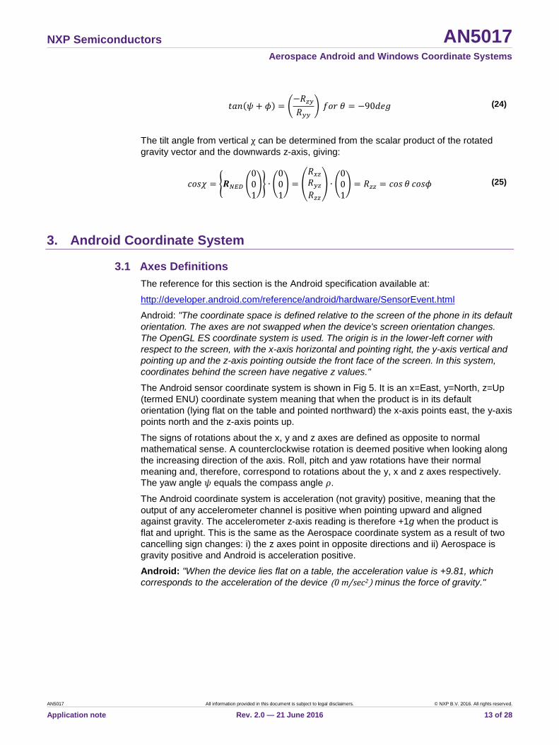
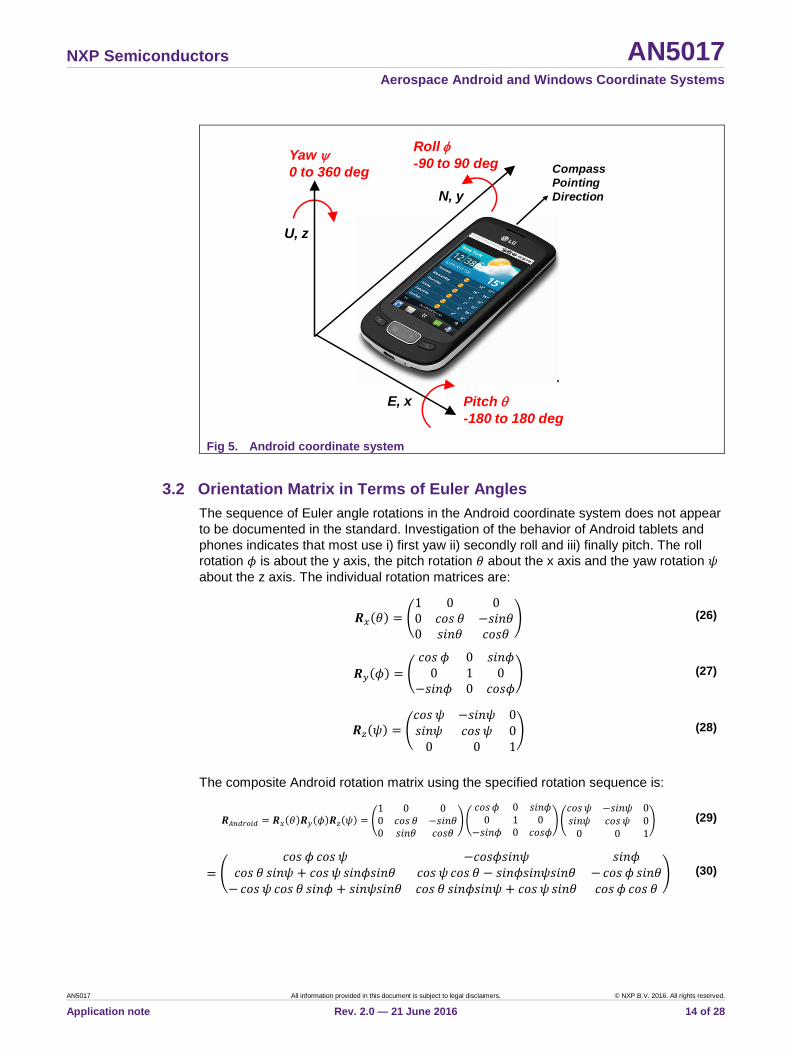
The Android sensor coordinate system is shown in Fig 5. It is an x=East, y=North, z=Up (termed ENU) coordinate system meaning that when the product is in its default orientation (lying flat on the table and pointed northward) the x-axis points east, the y-axis points north and the z-axis points up.
The signs of rotations about the x, y and z axes are defined as opposite to normal mathematical sense. A counterclockwise rotation is deemed positive when looking along the increasing direction of the axis. Roll, pitch and yaw rotations have their normal meaning and, therefore, correspond to rotations about the y, x and z axes respectively. The yaw angle 𝜓𝜓 equals the compass angle 𝜌𝜌.
The Android coordinate system is acceleration (not gravity) positive, meaning that the output of any accelerometer channel is positive when pointing upward and aligned against gravity. The accelerometer z-axis reading is therefore +1g when the product is flat and upright. This is the same as the Aerospace coordinate system as a result of two cancelling sign changes: i) the z axes point in opposite directions and ii) Aerospace is gravity positive and Android is acceleration positive.
Android: "When the device lies flat on a table, the acceleration value is +9.81, which corresponds to the acceleration of the device (0 m/sec2) minus the force of gravity."
NXP Semiconductors AN5017 Aerospace Android and Windows Coordinate Systems
AN5017 All information provided in this document is subject to legal disclaimers. © NXP B.V. 2016. All rights reserved.
Application note Rev. 2.0 — 21 June 2016 14 of 28
Fig 5. Android coordinate system
3.2 Orientation Matrix in Terms of Euler Angles The sequence of Euler angle rotations in the Android coordinate system does not appear to be documented in the standard. Investigation of the behavior of Android tablets and phones indicates that most use i) first yaw ii) secondly roll and iii) finally pitch. The roll rotation 𝜙𝜙 is about the y axis, the pitch rotation 𝜃𝜃 about the x axis and the yaw rotation 𝜓𝜓 about the z axis. The individual rotation matrices are:
𝑹𝑹𝑥𝑥(𝜃𝜃) = �1 0 00 𝑐𝑐𝑐𝑐𝑐𝑐 𝜃𝜃 −𝑐𝑐𝑠𝑠𝑠𝑠𝜃𝜃0 𝑐𝑐𝑠𝑠𝑠𝑠𝜃𝜃 𝑐𝑐𝑐𝑐𝑐𝑐𝜃𝜃
� (26)
𝑹𝑹𝑦𝑦(𝜙𝜙) = �𝑐𝑐𝑐𝑐𝑐𝑐 𝜙𝜙 0 𝑐𝑐𝑠𝑠𝑠𝑠𝜙𝜙
0 1 0−𝑐𝑐𝑠𝑠𝑠𝑠𝜙𝜙 0 𝑐𝑐𝑐𝑐𝑐𝑐𝜙𝜙
� (27)
𝑹𝑹𝑧𝑧(𝜓𝜓) = �𝑐𝑐𝑐𝑐𝑐𝑐 𝜓𝜓 −𝑐𝑐𝑠𝑠𝑠𝑠𝜓𝜓 0𝑐𝑐𝑠𝑠𝑠𝑠𝜓𝜓 𝑐𝑐𝑐𝑐𝑐𝑐 𝜓𝜓 0
0 0 1� (28)
The composite Android rotation matrix using the specified rotation sequence is:
𝑹𝑹𝐴𝐴𝐴𝐴𝐴𝐴𝐴𝐴𝐴𝐴𝐴𝐴𝐴𝐴 = 𝑹𝑹𝑥𝑥(𝜃𝜃)𝑹𝑹𝑦𝑦(𝜙𝜙)𝑹𝑹𝑧𝑧(𝜓𝜓) = �1 0 00 𝑐𝑐𝑐𝑐𝑐𝑐 𝜃𝜃 −𝑐𝑐𝑠𝑠𝑠𝑠𝜃𝜃0 𝑐𝑐𝑠𝑠𝑠𝑠𝜃𝜃 𝑐𝑐𝑐𝑐𝑐𝑐𝜃𝜃
��𝑐𝑐𝑐𝑐𝑐𝑐𝜙𝜙 0 𝑐𝑐𝑠𝑠𝑠𝑠𝜙𝜙
0 1 0−𝑐𝑐𝑠𝑠𝑠𝑠𝜙𝜙 0 𝑐𝑐𝑐𝑐𝑐𝑐𝜙𝜙
��𝑐𝑐𝑐𝑐𝑐𝑐𝜓𝜓 −𝑐𝑐𝑠𝑠𝑠𝑠𝜓𝜓 0𝑐𝑐𝑠𝑠𝑠𝑠𝜓𝜓 𝑐𝑐𝑐𝑐𝑐𝑐𝜓𝜓 0
0 0 1� (29)
= �𝑐𝑐𝑐𝑐𝑐𝑐 𝜙𝜙 𝑐𝑐𝑐𝑐𝑐𝑐 𝜓𝜓 −𝑐𝑐𝑐𝑐𝑐𝑐𝜙𝜙𝑐𝑐𝑠𝑠𝑠𝑠𝜓𝜓 𝑐𝑐𝑠𝑠𝑠𝑠𝜙𝜙
𝑐𝑐𝑐𝑐𝑐𝑐 𝜃𝜃 𝑐𝑐𝑠𝑠𝑠𝑠𝜓𝜓 + 𝑐𝑐𝑐𝑐𝑐𝑐 𝜓𝜓 𝑐𝑐𝑠𝑠𝑠𝑠𝜙𝜙𝑐𝑐𝑠𝑠𝑠𝑠𝜃𝜃 𝑐𝑐𝑐𝑐𝑐𝑐 𝜓𝜓 𝑐𝑐𝑐𝑐𝑐𝑐 𝜃𝜃 − 𝑐𝑐𝑠𝑠𝑠𝑠𝜙𝜙𝑐𝑐𝑠𝑠𝑠𝑠𝜓𝜓𝑐𝑐𝑠𝑠𝑠𝑠𝜃𝜃 − 𝑐𝑐𝑐𝑐𝑐𝑐 𝜙𝜙 𝑐𝑐𝑠𝑠𝑠𝑠𝜃𝜃− 𝑐𝑐𝑐𝑐𝑐𝑐 𝜓𝜓 𝑐𝑐𝑐𝑐𝑐𝑐 𝜃𝜃 𝑐𝑐𝑠𝑠𝑠𝑠𝜙𝜙 + 𝑐𝑐𝑠𝑠𝑠𝑠𝜓𝜓𝑐𝑐𝑠𝑠𝑠𝑠𝜃𝜃 𝑐𝑐𝑐𝑐𝑐𝑐 𝜃𝜃 𝑐𝑐𝑠𝑠𝑠𝑠𝜙𝜙𝑐𝑐𝑠𝑠𝑠𝑠𝜓𝜓 + 𝑐𝑐𝑐𝑐𝑐𝑐 𝜓𝜓 𝑐𝑐𝑠𝑠𝑠𝑠𝜃𝜃 𝑐𝑐𝑐𝑐𝑐𝑐 𝜙𝜙 𝑐𝑐𝑐𝑐𝑐𝑐 𝜃𝜃
� (30)
N, y
E, x
U, z
Compass Pointing Direction
Roll φ-90 to 90 degYaw ψ
0 to 360 deg
Pitch θ-180 to 180 deg
NXP Semiconductors AN5017 Aerospace Android and Windows Coordinate Systems
AN5017 All information provided in this document is subject to legal disclaimers. © NXP B.V. 2016. All rights reserved.
Application note Rev. 2.0 — 21 June 2016 15 of 28
3.3 Orientation Quaternion in Terms of Euler Angles The individual Euler angle rotation quaternions in the Android coordinate system are:
𝑞𝑞𝑥𝑥(𝜃𝜃) = 𝑐𝑐𝑐𝑐𝑐𝑐 �𝜃𝜃2� − 𝒊𝒊𝑐𝑐𝑠𝑠𝑠𝑠 �
𝜃𝜃2� (31)
𝑞𝑞𝑦𝑦(𝜙𝜙) = 𝑐𝑐𝑐𝑐𝑐𝑐 �𝜙𝜙2� − 𝒋𝒋𝑐𝑐𝑠𝑠𝑠𝑠 �
𝜙𝜙2� (32)
𝑞𝑞𝑧𝑧(𝜓𝜓) = 𝑐𝑐𝑐𝑐𝑐𝑐 �𝜓𝜓2� − 𝒌𝒌𝑐𝑐𝑠𝑠𝑠𝑠 �
𝜓𝜓2� (33)
The Android rotation quaternion 𝑞𝑞𝑧𝑧𝑦𝑦𝑥𝑥 = 𝑞𝑞𝑧𝑧(𝜓𝜓)𝑞𝑞𝑦𝑦(𝜙𝜙)𝑞𝑞𝑥𝑥(𝜃𝜃) evaluates to:
𝑞𝑞𝑧𝑧𝑦𝑦𝑥𝑥 = 𝑞𝑞𝑧𝑧(𝜓𝜓)𝑞𝑞𝑦𝑦(𝜙𝜙)𝑞𝑞𝑥𝑥(𝜃𝜃) = �𝑐𝑐𝑐𝑐𝑐𝑐 �𝜓𝜓2� − 𝒌𝒌𝑐𝑐𝑠𝑠𝑠𝑠 �
𝜓𝜓2�� �𝑐𝑐𝑐𝑐𝑐𝑐 �
𝜙𝜙2� − 𝒋𝒋𝑐𝑐𝑠𝑠𝑠𝑠 �
𝜙𝜙2�� �𝑐𝑐𝑐𝑐𝑐𝑐 �
𝜃𝜃2� − 𝒊𝒊𝑐𝑐𝑠𝑠𝑠𝑠 �
𝜃𝜃2�� (34)
= �𝑐𝑐𝑐𝑐𝑐𝑐 �𝜓𝜓2� 𝑐𝑐𝑐𝑐𝑐𝑐 �
𝜃𝜃2� 𝑐𝑐𝑐𝑐𝑐𝑐 �
𝜙𝜙2� − 𝑐𝑐𝑠𝑠𝑠𝑠 �
𝜓𝜓2� 𝑐𝑐𝑠𝑠𝑠𝑠 �
𝜃𝜃2� 𝑐𝑐𝑠𝑠𝑠𝑠 �
𝜙𝜙2��
− �𝑐𝑐𝑐𝑐𝑐𝑐 �𝜓𝜓2� 𝑐𝑐𝑠𝑠𝑠𝑠 �
𝜃𝜃2� 𝑐𝑐𝑐𝑐𝑐𝑐 �
𝜙𝜙2� + 𝑐𝑐𝑠𝑠𝑠𝑠 �
𝜓𝜓2� 𝑐𝑐𝑐𝑐𝑐𝑐 �
𝜃𝜃2� 𝑐𝑐𝑠𝑠𝑠𝑠 �
𝜙𝜙2�� 𝒊𝒊
− �𝑐𝑐𝑐𝑐𝑐𝑐 �𝜓𝜓2� 𝑐𝑐𝑐𝑐𝑐𝑐 �
𝜃𝜃2� 𝑐𝑐𝑠𝑠𝑠𝑠 �
𝜙𝜙2� − 𝑐𝑐𝑠𝑠𝑠𝑠 �
𝜓𝜓2� 𝑐𝑐𝑠𝑠𝑠𝑠 �
𝜃𝜃2� 𝑐𝑐𝑐𝑐𝑐𝑐 �
𝜙𝜙2�� 𝒋𝒋
− �𝑐𝑐𝑠𝑠𝑠𝑠 �𝜓𝜓2� 𝑐𝑐𝑐𝑐𝑐𝑐 �
𝜃𝜃2� 𝑐𝑐𝑐𝑐𝑐𝑐 �
𝜙𝜙2� + 𝑐𝑐𝑐𝑐𝑐𝑐 �
𝜓𝜓2� 𝑐𝑐𝑠𝑠𝑠𝑠 �
𝜃𝜃2� 𝑐𝑐𝑠𝑠𝑠𝑠 �
𝜙𝜙2�� 𝒌𝒌
(35)
The elements of the Android quaternion 𝑞𝑞𝑧𝑧𝑦𝑦𝑥𝑥 are therefore:
𝑞𝑞0 = 𝑐𝑐𝑐𝑐𝑐𝑐 �𝜓𝜓2� 𝑐𝑐𝑐𝑐𝑐𝑐 �
𝜃𝜃2� 𝑐𝑐𝑐𝑐𝑐𝑐 �
𝜙𝜙2� − 𝑐𝑐𝑠𝑠𝑠𝑠 �
𝜓𝜓2� 𝑐𝑐𝑠𝑠𝑠𝑠 �
𝜃𝜃2� 𝑐𝑐𝑠𝑠𝑠𝑠 �
𝜙𝜙2� (36)
𝑞𝑞1 = −𝑐𝑐𝑐𝑐𝑐𝑐 �𝜓𝜓2� 𝑐𝑐𝑠𝑠𝑠𝑠 �
𝜃𝜃2� 𝑐𝑐𝑐𝑐𝑐𝑐 �
𝜙𝜙2� − 𝑐𝑐𝑠𝑠𝑠𝑠 �
𝜓𝜓2� 𝑐𝑐𝑐𝑐𝑐𝑐 �
𝜃𝜃2� 𝑐𝑐𝑠𝑠𝑠𝑠 �
𝜙𝜙2� (37)
𝑞𝑞2 = −𝑐𝑐𝑐𝑐𝑐𝑐 �𝜓𝜓2� 𝑐𝑐𝑐𝑐𝑐𝑐 �
𝜃𝜃2� 𝑐𝑐𝑠𝑠𝑠𝑠 �
𝜙𝜙2� + 𝑐𝑐𝑠𝑠𝑠𝑠 �
𝜓𝜓2� 𝑐𝑐𝑠𝑠𝑠𝑠 �
𝜃𝜃2� 𝑐𝑐𝑐𝑐𝑐𝑐 �
𝜙𝜙2� (38)
𝑞𝑞3 = −𝑐𝑐𝑠𝑠𝑠𝑠 �𝜓𝜓2� 𝑐𝑐𝑐𝑐𝑐𝑐 �
𝜃𝜃2� 𝑐𝑐𝑐𝑐𝑐𝑐 �
𝜙𝜙2� − 𝑐𝑐𝑐𝑐𝑐𝑐 �
𝜓𝜓2� 𝑐𝑐𝑠𝑠𝑠𝑠 �
𝜃𝜃2� 𝑐𝑐𝑠𝑠𝑠𝑠 �
𝜙𝜙2� (39)
3.4 Gimbal Lock Gimbal lock occurs in the Android coordinate system when the second roll rotation aligns the first yaw and third pitch rotations. This occurs at +90° roll and –90° roll. The number of degrees of freedom in the Euler angle description of the orientation, therefore, reduces from three to two and the pitch and yaw angles oscillate with only their sum and difference defined.

NXP Semiconductors AN5017 Aerospace Android and Windows Coordinate Systems
AN5017 All information provided in this document is subject to legal disclaimers. © NXP B.V. 2016. All rights reserved.
Application note Rev. 2.0 — 21 June 2016 16 of 28
At gimbal lock 𝜙𝜙 = 90𝑑𝑑𝑑𝑑𝑑𝑑, equation (30) simplifies to:
𝑹𝑹𝐴𝐴𝐴𝐴𝐴𝐴𝐴𝐴𝐴𝐴𝐴𝐴𝐴𝐴 = �0 0 1
𝑐𝑐𝑠𝑠𝑠𝑠(𝜓𝜓 + 𝜃𝜃) 𝑐𝑐𝑐𝑐𝑐𝑐(𝜓𝜓 + 𝜃𝜃) 0−𝑐𝑐𝑐𝑐𝑐𝑐(𝜓𝜓 + 𝜃𝜃) 𝑐𝑐𝑠𝑠𝑠𝑠(𝜓𝜓 + 𝜃𝜃) 0
� 𝑓𝑓𝑐𝑐𝑓𝑓 𝜙𝜙 = 90𝑑𝑑𝑑𝑑𝑑𝑑 (40)
At gimbal lock 𝜙𝜙 = −90𝑑𝑑𝑑𝑑𝑑𝑑, equation (30) simplifies to:
𝑹𝑹𝐴𝐴𝐴𝐴𝐴𝐴𝐴𝐴𝐴𝐴𝐴𝐴𝐴𝐴 = �0 0 −1
𝑐𝑐𝑠𝑠𝑠𝑠(𝜓𝜓 − 𝜃𝜃) 𝑐𝑐𝑐𝑐𝑐𝑐(𝜓𝜓 − 𝜃𝜃) 0𝑐𝑐𝑐𝑐𝑐𝑐(𝜓𝜓 − 𝜃𝜃) −𝑐𝑐𝑠𝑠𝑠𝑠(𝜓𝜓 − 𝜃𝜃) 0
� 𝑓𝑓𝑐𝑐𝑓𝑓 𝜙𝜙 = −90𝑑𝑑𝑑𝑑𝑑𝑑 (41)
The orientation matrix and quaternion are stable, but the summed angle 𝜓𝜓 + 𝜃𝜃 or the differences angle 𝜓𝜓 − 𝜃𝜃 can be determined at the two gimbal lock orientations.
3.5 Euler Angle Discontinuities The Android rotation matrix 𝑹𝑹𝑥𝑥(𝜃𝜃)𝑹𝑹𝑦𝑦(𝜙𝜙)𝑹𝑹𝑧𝑧(𝜓𝜓) is equivalent to 𝑹𝑹𝑥𝑥(𝜃𝜃 + 𝜋𝜋)𝑹𝑹𝑦𝑦(𝜋𝜋 −𝜙𝜙)𝑹𝑹𝑧𝑧(𝜓𝜓 + 𝜋𝜋). By direct evaluation:
𝑹𝑹𝑥𝑥(𝜃𝜃 + 𝜋𝜋)𝑹𝑹𝑦𝑦(𝜋𝜋 − 𝜙𝜙)𝑹𝑹𝑧𝑧(𝜓𝜓 + 𝜋𝜋)
= �−𝑐𝑐𝑐𝑐𝑐𝑐(𝜋𝜋 − 𝜙𝜙) 𝑐𝑐𝑐𝑐𝑐𝑐𝜓𝜓 𝑐𝑐𝑐𝑐𝑐𝑐(𝜋𝜋 − 𝜙𝜙)𝑐𝑐𝑠𝑠𝑠𝑠𝜓𝜓 𝑐𝑐𝑠𝑠𝑠𝑠(𝜋𝜋 − 𝜙𝜙)
𝑐𝑐𝑐𝑐𝑐𝑐 𝜃𝜃 𝑐𝑐𝑠𝑠𝑠𝑠𝜓𝜓 + 𝑐𝑐𝑐𝑐𝑐𝑐 𝜓𝜓 𝑐𝑐𝑠𝑠𝑠𝑠(𝜋𝜋 − 𝜙𝜙)𝑐𝑐𝑠𝑠𝑠𝑠𝜃𝜃 𝑐𝑐𝑐𝑐𝑐𝑐𝜓𝜓 𝑐𝑐𝑐𝑐𝑐𝑐 𝜃𝜃 − 𝑐𝑐𝑠𝑠𝑠𝑠(𝜋𝜋 − 𝜙𝜙)𝑐𝑐𝑠𝑠𝑠𝑠𝜓𝜓𝑐𝑐𝑠𝑠𝑠𝑠𝜃𝜃 𝑐𝑐𝑐𝑐𝑐𝑐(𝜋𝜋 − 𝜙𝜙) 𝑐𝑐𝑠𝑠𝑠𝑠𝜃𝜃−𝑐𝑐𝑐𝑐𝑐𝑐𝜓𝜓 𝑐𝑐𝑐𝑐𝑐𝑐 𝜃𝜃 𝑐𝑐𝑠𝑠𝑠𝑠(𝜋𝜋 − 𝜙𝜙) + 𝑐𝑐𝑠𝑠𝑠𝑠𝜓𝜓𝑐𝑐𝑠𝑠𝑠𝑠𝜃𝜃 𝑐𝑐𝑐𝑐𝑐𝑐 𝜃𝜃 𝑐𝑐𝑠𝑠𝑠𝑠(𝜋𝜋 − 𝜙𝜙)𝑐𝑐𝑠𝑠𝑠𝑠𝜓𝜓 + 𝑐𝑐𝑐𝑐𝑐𝑐 𝜓𝜓 𝑐𝑐𝑠𝑠𝑠𝑠𝜃𝜃 −𝑐𝑐𝑐𝑐𝑐𝑐(𝜋𝜋 − 𝜙𝜙) 𝑐𝑐𝑐𝑐𝑐𝑐 𝜃𝜃
� (42)
= �𝑐𝑐𝑐𝑐𝑐𝑐 𝜙𝜙 𝑐𝑐𝑐𝑐𝑐𝑐 𝜓𝜓 −𝑐𝑐𝑐𝑐𝑐𝑐𝜙𝜙𝑐𝑐𝑠𝑠𝑠𝑠𝜓𝜓 𝑐𝑐𝑠𝑠𝑠𝑠𝜙𝜙
𝑐𝑐𝑐𝑐𝑐𝑐 𝜃𝜃 𝑐𝑐𝑠𝑠𝑠𝑠𝜓𝜓 + 𝑐𝑐𝑐𝑐𝑐𝑐 𝜓𝜓 𝑐𝑐𝑠𝑠𝑠𝑠𝜙𝜙𝑐𝑐𝑠𝑠𝑠𝑠𝜃𝜃 𝑐𝑐𝑐𝑐𝑐𝑐 𝜓𝜓 𝑐𝑐𝑐𝑐𝑐𝑐 𝜃𝜃 − 𝑐𝑐𝑠𝑠𝑠𝑠𝜙𝜙𝑐𝑐𝑠𝑠𝑠𝑠𝜓𝜓𝑐𝑐𝑠𝑠𝑠𝑠𝜃𝜃 − 𝑐𝑐𝑐𝑐𝑐𝑐𝜙𝜙 𝑐𝑐𝑠𝑠𝑠𝑠𝜃𝜃− 𝑐𝑐𝑐𝑐𝑐𝑐 𝜓𝜓 𝑐𝑐𝑐𝑐𝑐𝑐 𝜃𝜃 𝑐𝑐𝑠𝑠𝑠𝑠𝜙𝜙 + 𝑐𝑐𝑠𝑠𝑠𝑠𝜓𝜓𝑐𝑐𝑠𝑠𝑠𝑠𝜃𝜃 𝑐𝑐𝑐𝑐𝑐𝑐 𝜃𝜃 𝑐𝑐𝑠𝑠𝑠𝑠𝜙𝜙𝑐𝑐𝑠𝑠𝑠𝑠𝜓𝜓 + 𝑐𝑐𝑐𝑐𝑐𝑐 𝜓𝜓 𝑐𝑐𝑠𝑠𝑠𝑠𝜃𝜃 𝑐𝑐𝑐𝑐𝑐𝑐 𝜙𝜙 𝑐𝑐𝑐𝑐𝑐𝑐 𝜃𝜃
� = 𝑹𝑹𝑥𝑥(𝜃𝜃)𝑹𝑹𝑦𝑦(𝜙𝜙)𝑹𝑹𝑧𝑧(𝜓𝜓) (43)
Equations (42) and (43) show that there are two solutions for the Android Euler angles for a given rotation matrix. If ϕ, θ and ψ are one solution for the roll, pitch and yaw angles for a given orientation matrix, then so is the solution given by roll angle 180° minus ϕ, pitch angle 180° plus θ and yaw angle 180° plus ψ.
The Android specification removes the two solutions by restricting the roll angle θ to the range –90° to +90°. From the Android specification, where all values are angles in degrees:
Android: “values[0]: Azimuth, angle between the magnetic north direction and the y-axis, around the z-axis (0 to 359). 0=North, 90=East, 180=South, 270=West
values[1]: Pitch, rotation around x-axis (–180° to 180°), with positive values when the z-axis moves toward the y-axis.
values[2]: Roll, rotation around y-axis (–90° to 90°), with positive values when the x-axis moves toward the z-axis.”
Equations (42) and (43) state that whenever the roll angle is above 90o or less than -90o then the pitch angle should increase by 180o (the 𝑹𝑹𝑥𝑥(𝜃𝜃 + 𝜋𝜋) term), the roll angle should be negated and 180o added (the 𝑹𝑹𝑦𝑦(𝜋𝜋 − 𝜙𝜙) term) and the yaw/compass heading should increase by 180o (the 𝑹𝑹𝑧𝑧(𝜓𝜓 + 𝜋𝜋) term). These discontinuities are shown in Fig 6 through Fig 8.
NXP Semiconductors AN5017 Aerospace Android and Windows Coordinate Systems
AN5017 All information provided in this document is subject to legal disclaimers. © NXP B.V. 2016. All rights reserved.
Application note Rev. 2.0 — 21 June 2016 17 of 28
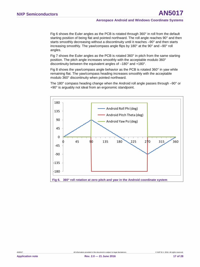
Fig 6 shows the Euler angles as the PCB is rotated through 360° in roll from the default starting position of being flat and pointed northward. The roll angle reaches 90° and then starts smoothly decreasing without a discontinuity until it reaches –90° and then starts increasing smoothly. The yaw/compass angle flips by 180° at the 90° and –90° roll angles.
Fig 7 shows the Euler angles as the PCB is rotated 360° in pitch from the same starting position. The pitch angle increases smoothly with the acceptable modulo 360° discontinuity between the equivalent angles of –180° and +180°.
Fig 8 shows the yaw/compass angle behavior as the PCB is rotated 360° in yaw while remaining flat. The yaw/compass heading increases smoothly with the acceptable modulo 360° discontinuity when pointed northward.
The 180° compass heading change when the Android roll angle passes through –90° or +90° is arguably not ideal from an ergonomic standpoint.
Fig 6. 360° roll rotation at zero pitch and yaw in the Android coordinate system
-180
-135
-90
-45
0
45
90
135
180
0 45 90 135 180 225 270 315 360
Android Roll Phi (deg)
Android Pitch Theta (deg)
Android Yaw Psi (deg)

NXP Semiconductors AN5017 Aerospace Android and Windows Coordinate Systems
AN5017 All information provided in this document is subject to legal disclaimers. © NXP B.V. 2016. All rights reserved.
Application note Rev. 2.0 — 21 June 2016 18 of 28
Fig 7. 360° pitch rotation at zero roll and yaw in the Android coordinate system
Fig 8. 360° yaw rotation at zero roll and pitch in the Android coordinate system
3.6 Calculation of Euler Angles from Rotation Matrix This section documents function fAndroidAnglesDegFromRotationMatrix, which computes the Euler angles from the Android rotation matrix as defined in equation (30).
-180
-135
-90
-45
0
45
90
135
180
0 45 90 135 180 225 270 315 360
Android Roll Phi (deg)
Android Pitch Theta (deg)
Android Yaw Psi (deg)
0
45
90
135
180
225
270
315
360
0 45 90 135 180 225 270 315 360
Android Roll Phi (deg)
Android Pitch Theta (deg)
Android Yaw Psi (deg)
NXP Semiconductors AN5017 Aerospace Android and Windows Coordinate Systems
AN5017 All information provided in this document is subject to legal disclaimers. © NXP B.V. 2016. All rights reserved.
Application note Rev. 2.0 — 21 June 2016 19 of 28
The solution for the three Android Euler angles is:
𝜙𝜙 = 𝑐𝑐𝑠𝑠𝑠𝑠−1(𝑅𝑅𝑥𝑥𝑧𝑧),−90 ≤ 𝜙𝜙 < 90 𝑑𝑑𝑑𝑑𝑑𝑑 (44)
𝜃𝜃 = 𝑡𝑡𝑡𝑡𝑠𝑠−1 �−𝑅𝑅𝑦𝑦𝑧𝑧𝑅𝑅𝑧𝑧𝑧𝑧
� ,−180 ≤ 𝜃𝜃 < 180 𝑑𝑑𝑑𝑑𝑑𝑑 (45)
𝜓𝜓 = 𝑡𝑡𝑡𝑡𝑠𝑠−1 �−𝑅𝑅𝑥𝑥𝑦𝑦𝑅𝑅𝑥𝑥𝑥𝑥
� , 0 ≤ 𝜓𝜓 < 360 𝑑𝑑𝑑𝑑𝑑𝑑 (46)
The Android compass heading angle ρ always equals the yaw angle ψ:
𝜌𝜌 = 𝜓𝜓 (47)
At gimbal lock, equations (40) and (41) give:
𝑡𝑡𝑡𝑡𝑠𝑠(𝜓𝜓 + 𝜃𝜃) = �𝑅𝑅𝑦𝑦𝑥𝑥𝑅𝑅𝑦𝑦𝑦𝑦
� 𝑓𝑓𝑐𝑐𝑓𝑓 𝜙𝜙 = 90𝑑𝑑𝑑𝑑𝑑𝑑 (48)
𝑡𝑡𝑡𝑡𝑠𝑠(𝜓𝜓 − 𝜃𝜃) = �𝑅𝑅𝑦𝑦𝑥𝑥𝑅𝑅𝑦𝑦𝑦𝑦
� 𝑓𝑓𝑐𝑐𝑓𝑓 𝜙𝜙 = −90𝑑𝑑𝑑𝑑𝑑𝑑 (49)
The tilt angle from vertical χ can be determined from the scalar product of the rotated gravity vector and the downwards z-axis giving:
𝑐𝑐𝑐𝑐𝑐𝑐𝜒𝜒 = �𝑹𝑹𝐴𝐴𝐴𝐴𝐴𝐴𝐴𝐴𝐴𝐴𝐴𝐴𝐴𝐴 �001�� ∙ �
001� = �
𝑅𝑅𝑥𝑥𝑧𝑧𝑅𝑅𝑦𝑦𝑧𝑧𝑅𝑅𝑧𝑧𝑧𝑧
� ∙ �001� = 𝑅𝑅𝑧𝑧𝑧𝑧 = 𝑐𝑐𝑐𝑐𝑐𝑐 𝜃𝜃 𝑐𝑐𝑐𝑐𝑐𝑐𝜙𝜙 (50)
4. Windows 8 Coordinate System
4.1 Axes Definitions The reference for this section is the Microsoft specification: "Integrating Motion and Orientation Sensors" available for download at:
http://msdn.microsoft.com/en-us/library/windows/hardware/dn642102(v=vs.85).aspx
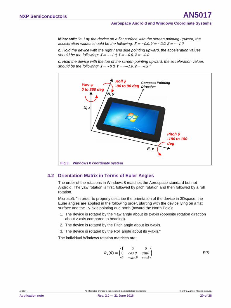
The Windows 8 coordinate system is shown in Fig 9. It is an x=East, y=North, z=Up (termed ENU) coordinate system, similar to the Android coordinate system.
The sign of rotations about the x, y and z axes is opposite to Android and, therefore, compatible with normal mathematical usage. A consequence is that the Windows 8 compass heading angle ρ has the opposite sense to the Windows 8 yaw angle ψ and ρ=360o–ψ.
The Windows 8 coordinate system is gravity (not acceleration) positive, meaning that the output of any accelerometer channel is negative when pointing up and aligned against gravity. The accelerometer z-axis reading is, therefore, –1g when the product is flat and upright.
NXP Semiconductors AN5017 Aerospace Android and Windows Coordinate Systems
AN5017 All information provided in this document is subject to legal disclaimers. © NXP B.V. 2016. All rights reserved.
Application note Rev. 2.0 — 21 June 2016 20 of 28
Microsoft: "a. Lay the device on a flat surface with the screen pointing upward, the acceleration values should be the following: X = ~0.0, Y = ~0.0, Z = ~–1.0
b. Hold the device with the right hand side pointing upward, the acceleration values should be the following: X = ~–1.0, Y = ~0.0, Z = ~0.0
c. Hold the device with the top of the screen pointing upward, the acceleration values should be the following: X = ~0.0, Y = ~–1.0, Z = ~0.0"
Fig 9. Windows 8 coordinate system
4.2 Orientation Matrix in Terms of Euler Angles The order of the rotations in Windows 8 matches the Aerospace standard but not Android. The yaw rotation is first, followed by pitch rotation and then followed by a roll rotation.
Microsoft: "In order to properly describe the orientation of the device in 3Dspace, the Euler angles are applied in the following order, starting with the device lying on a flat surface and the +y-axis pointing due north (toward the North Pole): 1. The device is rotated by the Yaw angle about its z-axis (opposite rotation direction
about z-axis compared to heading). 2. The device is rotated by the Pitch angle about its x-axis. 3. The device is rotated by the Roll angle about its y-axis."
The individual Windows rotation matrices are:
𝑹𝑹𝒙𝒙(𝜃𝜃) = �1 0 00 𝑐𝑐𝑐𝑐𝑐𝑐 𝜃𝜃 𝑐𝑐𝑠𝑠𝑠𝑠𝜃𝜃0 −𝑐𝑐𝑠𝑠𝑠𝑠𝜃𝜃 𝑐𝑐𝑐𝑐𝑐𝑐𝜃𝜃
� (51)
N, y
E, x
U, z
Compass Pointing Direction
Roll φ-90 to 90 degYaw ψ
0 to 360 deg
Pitch θ-180 to 180 deg

NXP Semiconductors AN5017 Aerospace Android and Windows Coordinate Systems
AN5017 All information provided in this document is subject to legal disclaimers. © NXP B.V. 2016. All rights reserved.
Application note Rev. 2.0 — 21 June 2016 21 of 28
𝑹𝑹𝒚𝒚(𝜙𝜙) = �𝑐𝑐𝑐𝑐𝑐𝑐 𝜙𝜙 0 −𝑐𝑐𝑠𝑠𝑠𝑠𝜙𝜙
0 1 0𝑐𝑐𝑠𝑠𝑠𝑠𝜙𝜙 0 𝑐𝑐𝑐𝑐𝑐𝑐𝜙𝜙
� (52)
𝑹𝑹𝒛𝒛(𝜓𝜓) = �−𝑐𝑐𝑐𝑐𝑐𝑐 𝜓𝜓 𝑐𝑐𝑠𝑠𝑠𝑠𝜓𝜓 0𝑐𝑐𝑠𝑠𝑠𝑠𝜓𝜓 𝑐𝑐𝑐𝑐𝑐𝑐 𝜓𝜓 0
0 0 1� (53)
The composite Windows 8 rotation matrix using the Microsoft rotation sequence is:
𝑹𝑹 = 𝑹𝑹𝒚𝒚(𝜙𝜙)𝑹𝑹𝒙𝒙(𝜃𝜃)𝑹𝑹𝒛𝒛(𝜓𝜓) = �𝑐𝑐𝑐𝑐𝑐𝑐 𝜙𝜙 0 −𝑐𝑐𝑠𝑠𝑠𝑠𝜙𝜙
0 1 0𝑐𝑐𝑠𝑠𝑠𝑠𝜙𝜙 0 𝑐𝑐𝑐𝑐𝑐𝑐𝜙𝜙
��1 0 00 𝑐𝑐𝑐𝑐𝑐𝑐 𝜃𝜃 𝑐𝑐𝑠𝑠𝑠𝑠𝜃𝜃0 −𝑐𝑐𝑠𝑠𝑠𝑠𝜃𝜃 𝑐𝑐𝑐𝑐𝑐𝑐𝜃𝜃
��−𝑐𝑐𝑐𝑐𝑐𝑐𝜓𝜓 𝑐𝑐𝑠𝑠𝑠𝑠𝜓𝜓 0𝑐𝑐𝑠𝑠𝑠𝑠𝜓𝜓 𝑐𝑐𝑐𝑐𝑐𝑐𝜓𝜓 0
0 0 1� (54)
= �𝑐𝑐𝑐𝑐𝑐𝑐𝜙𝜙 𝑐𝑐𝑐𝑐𝑐𝑐𝜓𝜓 − 𝑐𝑐𝑠𝑠𝑠𝑠𝜙𝜙𝑐𝑐𝑠𝑠𝑠𝑠𝜃𝜃𝑐𝑐𝑠𝑠𝑠𝑠𝜓𝜓 𝑐𝑐𝑐𝑐𝑐𝑐𝜙𝜙𝑐𝑐𝑠𝑠𝑠𝑠𝜓𝜓 + 𝑐𝑐𝑐𝑐𝑐𝑐 𝜓𝜓 𝑐𝑐𝑠𝑠𝑠𝑠𝜙𝜙𝑐𝑐𝑠𝑠𝑠𝑠𝜃𝜃 −𝑐𝑐𝑠𝑠𝑠𝑠𝜙𝜙 𝑐𝑐𝑐𝑐𝑐𝑐 𝜃𝜃
−𝑐𝑐𝑐𝑐𝑐𝑐 𝜃𝜃 𝑐𝑐𝑠𝑠𝑠𝑠𝜓𝜓 𝑐𝑐𝑐𝑐𝑐𝑐 𝜃𝜃 𝑐𝑐𝑐𝑐𝑐𝑐𝜓𝜓 𝑐𝑐𝑠𝑠𝑠𝑠𝜃𝜃𝑐𝑐𝑐𝑐𝑐𝑐𝜓𝜓 𝑐𝑐𝑠𝑠𝑠𝑠𝜙𝜙 + 𝑐𝑐𝑐𝑐𝑐𝑐𝜙𝜙 𝑐𝑐𝑠𝑠𝑠𝑠𝜓𝜓𝑐𝑐𝑠𝑠𝑠𝑠𝜃𝜃 𝑐𝑐𝑠𝑠𝑠𝑠𝜙𝜙𝑐𝑐𝑠𝑠𝑠𝑠𝜓𝜓 − 𝑐𝑐𝑐𝑐𝑐𝑐 𝜙𝜙 𝑐𝑐𝑐𝑐𝑐𝑐𝜓𝜓 𝑐𝑐𝑠𝑠𝑠𝑠𝜃𝜃 𝑐𝑐𝑐𝑐𝑐𝑐𝜙𝜙 𝑐𝑐𝑐𝑐𝑐𝑐 𝜃𝜃
� (55)
4.3 Orientation Quaternion in Terms of Euler Angles The individual Euler angle rotation quaternions in the Windows 8 coordinate system are:
𝑞𝑞𝑥𝑥(𝜃𝜃) = 𝑐𝑐𝑐𝑐𝑐𝑐 �𝜃𝜃2� + 𝒊𝒊𝑐𝑐𝑠𝑠𝑠𝑠 �
𝜃𝜃2� (56)
𝑞𝑞𝑥𝑥(𝜃𝜃) = 𝑐𝑐𝑐𝑐𝑐𝑐 �𝜃𝜃2� + 𝒊𝒊𝑐𝑐𝑠𝑠𝑠𝑠 �
𝜃𝜃2� (57)
𝑞𝑞𝑧𝑧(𝜓𝜓) = 𝑐𝑐𝑐𝑐𝑐𝑐 �𝜓𝜓2� + 𝒌𝒌𝑐𝑐𝑠𝑠𝑠𝑠 �
𝜓𝜓2� (58)
The Windows 8 rotation quaternion 𝑞𝑞𝑧𝑧𝑥𝑥𝑦𝑦 = 𝑞𝑞𝑧𝑧(𝜓𝜓)𝑞𝑞𝑥𝑥(𝜃𝜃)𝑞𝑞𝑦𝑦(𝜙𝜙) evaluates to:
𝑞𝑞𝑧𝑧𝑥𝑥𝑦𝑦 = 𝑞𝑞𝑧𝑧(𝜓𝜓)𝑞𝑞𝑥𝑥(𝜃𝜃)𝑞𝑞𝑦𝑦(𝜙𝜙) = �𝑐𝑐𝑐𝑐𝑐𝑐 �𝜓𝜓2� + 𝒌𝒌𝑐𝑐𝑠𝑠𝑠𝑠 �
𝜓𝜓2�� �𝑐𝑐𝑐𝑐𝑐𝑐 �
𝜃𝜃2�+ 𝒊𝒊𝑐𝑐𝑠𝑠𝑠𝑠 �
𝜃𝜃2�� �𝑐𝑐𝑐𝑐𝑐𝑐 �
𝜙𝜙2� + 𝒋𝒋𝑐𝑐𝑠𝑠𝑠𝑠 �
𝜙𝜙2�� (59)
= �𝑐𝑐𝑐𝑐𝑐𝑐 �𝜓𝜓2� 𝑐𝑐𝑐𝑐𝑐𝑐 �
𝜃𝜃2� 𝑐𝑐𝑐𝑐𝑐𝑐 �
𝜙𝜙2� − 𝑐𝑐𝑠𝑠𝑠𝑠 �
𝜓𝜓2� 𝑐𝑐𝑠𝑠𝑠𝑠 �
𝜃𝜃2� 𝑐𝑐𝑠𝑠𝑠𝑠 �
𝜙𝜙2��
+ �𝑐𝑐𝑐𝑐𝑐𝑐 �𝜓𝜓2� 𝑐𝑐𝑠𝑠𝑠𝑠 �
𝜃𝜃2� 𝑐𝑐𝑐𝑐𝑐𝑐 �
𝜙𝜙2� − 𝑐𝑐𝑠𝑠𝑠𝑠 �
𝜓𝜓2� 𝑐𝑐𝑐𝑐𝑐𝑐 �
𝜃𝜃2� 𝑐𝑐𝑠𝑠𝑠𝑠 �
𝜙𝜙2�� 𝒊𝒊
+ �𝑐𝑐𝑐𝑐𝑐𝑐 �𝜓𝜓2� 𝑐𝑐𝑐𝑐𝑐𝑐 �
𝜃𝜃2� 𝑐𝑐𝑠𝑠𝑠𝑠 �
𝜙𝜙2� + 𝑐𝑐𝑠𝑠𝑠𝑠 �
𝜓𝜓2� 𝑐𝑐𝑠𝑠𝑠𝑠 �
𝜃𝜃2� 𝑐𝑐𝑐𝑐𝑐𝑐 �
𝜙𝜙2�� 𝒋𝒋
+ �𝑐𝑐𝑠𝑠𝑠𝑠 �𝜓𝜓2� 𝑐𝑐𝑐𝑐𝑐𝑐 �
𝜃𝜃2� 𝑐𝑐𝑐𝑐𝑐𝑐 �
𝜙𝜙2� + 𝑐𝑐𝑐𝑐𝑐𝑐 �
𝜓𝜓2� 𝑐𝑐𝑠𝑠𝑠𝑠 �
𝜃𝜃2� 𝑐𝑐𝑠𝑠𝑠𝑠 �
𝜙𝜙2�� 𝒌𝒌
(60)
The elements of the Windows 8 quaternion 𝑞𝑞𝑧𝑧𝑥𝑥𝑦𝑦 are, therefore:
𝑞𝑞0 = 𝑐𝑐𝑐𝑐𝑐𝑐 �𝜓𝜓2� 𝑐𝑐𝑐𝑐𝑐𝑐 �
𝜃𝜃2� 𝑐𝑐𝑐𝑐𝑐𝑐 �
𝜙𝜙2� − 𝑐𝑐𝑠𝑠𝑠𝑠 �
𝜓𝜓2� 𝑐𝑐𝑠𝑠𝑠𝑠 �
𝜃𝜃2� 𝑐𝑐𝑠𝑠𝑠𝑠 �
𝜙𝜙2� (61)
𝑞𝑞1 = 𝑐𝑐𝑐𝑐𝑐𝑐 �𝜓𝜓2� 𝑐𝑐𝑠𝑠𝑠𝑠 �
𝜃𝜃2� 𝑐𝑐𝑐𝑐𝑐𝑐 �
𝜙𝜙2� − 𝑐𝑐𝑠𝑠𝑠𝑠 �
𝜓𝜓2� 𝑐𝑐𝑐𝑐𝑐𝑐 �
𝜃𝜃2� 𝑐𝑐𝑠𝑠𝑠𝑠 �
𝜙𝜙2� (62)
NXP Semiconductors AN5017 Aerospace Android and Windows Coordinate Systems
AN5017 All information provided in this document is subject to legal disclaimers. © NXP B.V. 2016. All rights reserved.
Application note Rev. 2.0 — 21 June 2016 22 of 28
𝑞𝑞2 = 𝑐𝑐𝑐𝑐𝑐𝑐 �𝜓𝜓2� 𝑐𝑐𝑐𝑐𝑐𝑐 �
𝜃𝜃2� 𝑐𝑐𝑠𝑠𝑠𝑠 �
𝜙𝜙2� + 𝑐𝑐𝑠𝑠𝑠𝑠 �
𝜓𝜓2� 𝑐𝑐𝑠𝑠𝑠𝑠 �
𝜃𝜃2� 𝑐𝑐𝑐𝑐𝑐𝑐 �
𝜙𝜙2� (63)
𝑞𝑞3 = 𝑐𝑐𝑠𝑠𝑠𝑠 �𝜓𝜓2� 𝑐𝑐𝑐𝑐𝑐𝑐 �
𝜃𝜃2� 𝑐𝑐𝑐𝑐𝑐𝑐 �
𝜙𝜙2� + 𝑐𝑐𝑐𝑐𝑐𝑐 �
𝜓𝜓2� 𝑐𝑐𝑠𝑠𝑠𝑠 �
𝜃𝜃2� 𝑐𝑐𝑠𝑠𝑠𝑠 �
𝜙𝜙2� (64)
4.4 Gimbal Lock Gimbal lock occurs in the Windows 8 coordinate system when the second pitch rotation aligns the first yaw and third roll rotations. This occurs at +90° pitch and –90° pitch angles. The number of degrees of freedom in the Euler angle description of the orientation therefore reduces from 3 to 2 and the roll and yaw angles oscillate with only their sum and difference defined.
At gimbal lock 𝜃𝜃 = 90𝑑𝑑𝑑𝑑𝑑𝑑, equation (55) simplifies to:
𝑹𝑹𝑊𝑊𝐴𝐴𝐴𝐴8 = �𝑐𝑐𝑐𝑐𝑐𝑐(𝜓𝜓 + 𝜙𝜙) 𝑐𝑐𝑠𝑠𝑠𝑠(𝜓𝜓 + 𝜙𝜙) 0
0 0 1𝑐𝑐𝑠𝑠𝑠𝑠(𝜓𝜓 + 𝜙𝜙) −𝑐𝑐𝑐𝑐𝑐𝑐(𝜓𝜓 + 𝜙𝜙) 0
� 𝑓𝑓𝑐𝑐𝑓𝑓 𝜃𝜃 = 90𝑑𝑑𝑑𝑑𝑑𝑑 (65)
At gimbal lock 𝜃𝜃 = −90𝑑𝑑𝑑𝑑𝑑𝑑, equation (55) simplifies to:
𝑹𝑹𝑊𝑊𝐴𝐴𝐴𝐴8 = �𝑐𝑐𝑐𝑐𝑐𝑐(𝜓𝜓 − 𝜙𝜙) 𝑐𝑐𝑠𝑠𝑠𝑠(𝜓𝜓 − 𝜙𝜙) 0
0 0 −1−𝑐𝑐𝑠𝑠𝑠𝑠(𝜓𝜓 − 𝜙𝜙) 𝑐𝑐𝑐𝑐𝑐𝑐(𝜓𝜓 − 𝜙𝜙) 0
� 𝑓𝑓𝑐𝑐𝑓𝑓 𝜃𝜃 = −90𝑑𝑑𝑑𝑑𝑑𝑑 (66)
The orientation matrix and quaternion are stable but only the summed angle 𝜓𝜓 + 𝜙𝜙 or the differenced angle 𝜓𝜓 − 𝜙𝜙 can be determined at the two gimbal lock orientations.
4.5 Euler Angle Discontinuities The Windows 8 rotation matrix 𝑹𝑹𝑦𝑦(𝜙𝜙)𝑹𝑹𝑥𝑥(𝜃𝜃)𝑹𝑹𝑧𝑧(𝜓𝜓) is equal to the matrix 𝑹𝑹𝑦𝑦(𝜙𝜙 +𝜋𝜋)𝑹𝑹𝑥𝑥(𝜋𝜋 − 𝜃𝜃)𝑹𝑹𝑧𝑧(𝜓𝜓 + 𝜋𝜋). By direct evaluation:
𝑹𝑹𝑦𝑦(𝜙𝜙 + 𝜋𝜋)𝑹𝑹𝑥𝑥(𝜋𝜋 − 𝜃𝜃)𝑹𝑹𝑧𝑧(𝜓𝜓 + 𝜋𝜋)
= �𝑐𝑐𝑐𝑐𝑐𝑐 𝜙𝜙 𝑐𝑐𝑐𝑐𝑐𝑐𝜓𝜓 − 𝑐𝑐𝑠𝑠𝑠𝑠𝜙𝜙𝑐𝑐𝑠𝑠𝑠𝑠𝜃𝜃𝑐𝑐𝑠𝑠𝑠𝑠𝜓𝜓 𝑐𝑐𝑐𝑐𝑐𝑐𝜙𝜙𝑐𝑐𝑠𝑠𝑠𝑠𝜓𝜓 + 𝑐𝑐𝑐𝑐𝑐𝑐𝜓𝜓 𝑐𝑐𝑠𝑠𝑠𝑠𝜙𝜙𝑐𝑐𝑠𝑠𝑠𝑠𝜃𝜃 −𝑐𝑐𝑐𝑐𝑐𝑐 𝜃𝜃 𝑐𝑐𝑠𝑠𝑠𝑠𝜙𝜙
−𝑐𝑐𝑐𝑐𝑐𝑐 𝜃𝜃 𝑐𝑐𝑠𝑠𝑠𝑠𝜓𝜓 𝑐𝑐𝑐𝑐𝑐𝑐𝜓𝜓 𝑐𝑐𝑐𝑐𝑐𝑐 𝜃𝜃 𝑐𝑐𝑠𝑠𝑠𝑠𝜃𝜃𝑐𝑐𝑐𝑐𝑐𝑐 𝜓𝜓 𝑐𝑐𝑠𝑠𝑠𝑠𝜙𝜙 + 𝑐𝑐𝑐𝑐𝑐𝑐 𝜙𝜙 𝑐𝑐𝑠𝑠𝑠𝑠𝜓𝜓𝑐𝑐𝑠𝑠𝑠𝑠𝜃𝜃 𝑐𝑐𝑠𝑠𝑠𝑠𝜙𝜙𝑐𝑐𝑠𝑠𝑠𝑠𝜓𝜓 − 𝑐𝑐𝑐𝑐𝑐𝑐𝜙𝜙 𝑐𝑐𝑐𝑐𝑐𝑐𝜓𝜓 𝑐𝑐𝑠𝑠𝑠𝑠𝜃𝜃 𝑐𝑐𝑐𝑐𝑐𝑐𝜙𝜙 𝑐𝑐𝑐𝑐𝑐𝑐 𝜃𝜃
� (67)
= �𝑐𝑐𝑐𝑐𝑐𝑐𝜙𝜙 𝑐𝑐𝑐𝑐𝑐𝑐𝜓𝜓 − 𝑐𝑐𝑠𝑠𝑠𝑠𝜙𝜙𝑐𝑐𝑠𝑠𝑠𝑠𝜃𝜃𝑐𝑐𝑠𝑠𝑠𝑠𝜓𝜓 𝑐𝑐𝑐𝑐𝑐𝑐𝜙𝜙𝑐𝑐𝑠𝑠𝑠𝑠𝜓𝜓 + 𝑐𝑐𝑐𝑐𝑐𝑐𝜓𝜓 𝑐𝑐𝑠𝑠𝑠𝑠𝜙𝜙𝑐𝑐𝑠𝑠𝑠𝑠𝜃𝜃 −𝑐𝑐𝑐𝑐𝑐𝑐 𝜃𝜃 𝑐𝑐𝑠𝑠𝑠𝑠𝜙𝜙
−𝑐𝑐𝑐𝑐𝑐𝑐 𝜃𝜃 𝑐𝑐𝑠𝑠𝑠𝑠𝜓𝜓 𝑐𝑐𝑐𝑐𝑐𝑐𝜓𝜓 𝑐𝑐𝑐𝑐𝑐𝑐 𝜃𝜃 𝑐𝑐𝑠𝑠𝑠𝑠𝜃𝜃𝑐𝑐𝑐𝑐𝑐𝑐 𝜓𝜓 𝑐𝑐𝑠𝑠𝑠𝑠𝜙𝜙 + 𝑐𝑐𝑐𝑐𝑐𝑐 𝜙𝜙 𝑐𝑐𝑠𝑠𝑠𝑠𝜓𝜓𝑐𝑐𝑠𝑠𝑠𝑠𝜃𝜃 𝑐𝑐𝑠𝑠𝑠𝑠𝜙𝜙𝑐𝑐𝑠𝑠𝑠𝑠𝜓𝜓 − 𝑐𝑐𝑐𝑐𝑐𝑐 𝜙𝜙 𝑐𝑐𝑐𝑐𝑐𝑐𝜓𝜓 𝑐𝑐𝑠𝑠𝑠𝑠𝜃𝜃 𝑐𝑐𝑐𝑐𝑐𝑐 𝜙𝜙 𝑐𝑐𝑐𝑐𝑐𝑐 𝜃𝜃
� = 𝑹𝑹𝑦𝑦(𝜙𝜙)𝑹𝑹𝑥𝑥(𝜃𝜃)𝑹𝑹𝑧𝑧(𝜓𝜓) (68)
Equations (67) and (68) show that there are two solutions for the Windows 8 Euler angles for a given rotation matrix. If ϕ, θ and ψ are one solution for the roll, pitch and yaw angles for a given orientation matrix, then so is the solution given by roll angle 180° plus ϕ, pitch angle 180° minus θ and yaw angle 180° plus ψ.
The Windows 8 specification removes the two solutions by restricting the roll angle θ to the range –90° to +90°.

NXP Semiconductors AN5017 Aerospace Android and Windows Coordinate Systems
AN5017 All information provided in this document is subject to legal disclaimers. © NXP B.V. 2016. All rights reserved.
Application note Rev. 2.0 — 21 June 2016 23 of 28
Microsoft: "The following ranges are used for the representation of Yaw, Pitch and Roll: • 0.0° ≤ Yaw < 360.0° • –180.0° ≤ Pitch < 180.0° • –90.0° ≤ Roll < 90.0°"
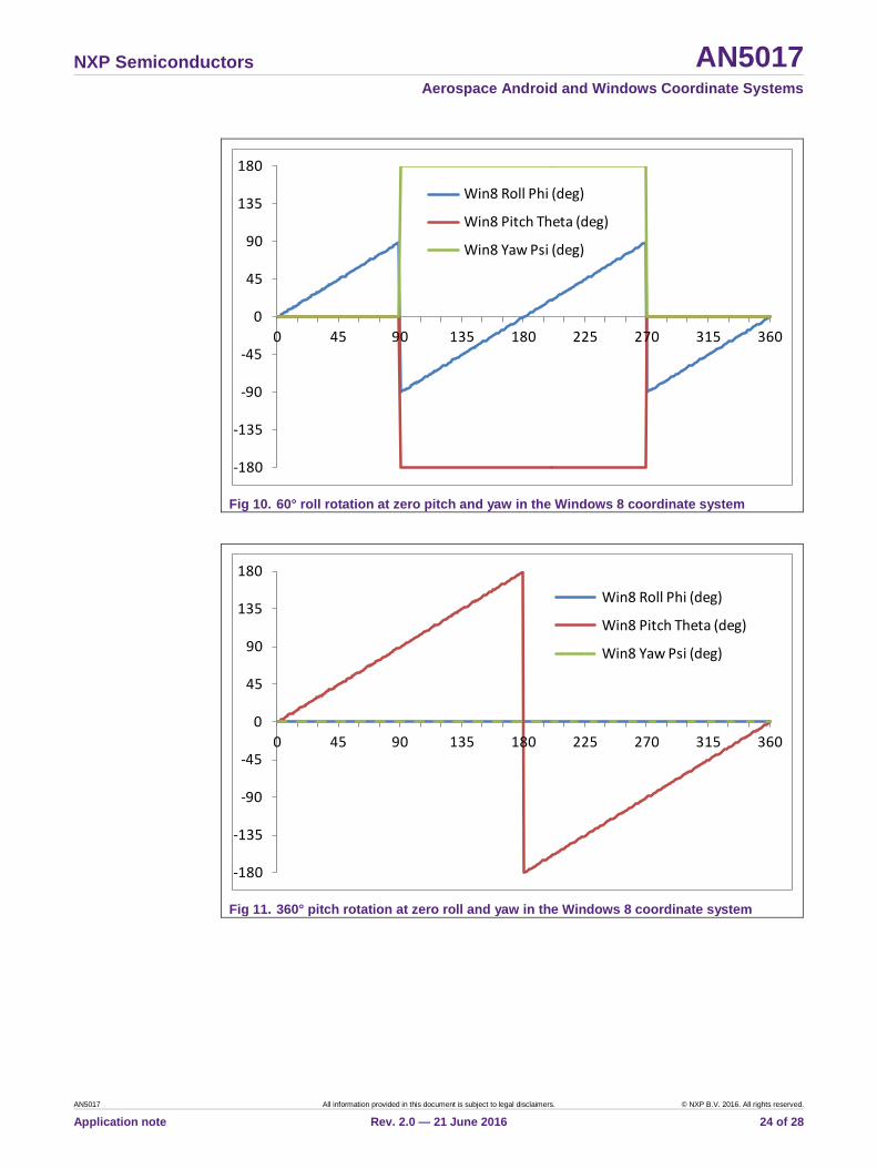
Equations (67) and (68) state that whenever the roll angle is above 90° or less than –90° then the roll angle should increase by 180° (the 𝑹𝑹𝑦𝑦(𝜙𝜙 + 𝜋𝜋) term), the pitch angle should be negated and 180° added (the Rx (π–θ) term) and the yaw/compass heading should increase by 180° (the 𝑹𝑹𝑧𝑧(𝜓𝜓 + 𝜋𝜋) term). These discontinuities are shown in Fig 10 through Fig 12 and should be compared with Figure 21 in the Microsoft Inc. specification: “Integrating Motion and Orientation Sensors”.
Fig 10 shows the Euler angles as the PCB is rotated through 360° in roll from the default starting position of being flat and pointed northward. The roll angle reaches 90°, has a discontinuity to –90°, increases to 90° and then has another discontinuity to –90°. The pitch and yaw/compass heading angles suffer 180° discontinuities at 90° and –90° roll angles.
Fig 11 shows the Euler angles as the PCB is rotated 360° in pitch from the same starting position. The pitch angle increases smoothly with the acceptable modulo 360° discontinuity between the equivalent angles of –180° and +180°.
Fig 12 shows the yaw/compass angle behavior as the PCB is rotated 360° in yaw while remaining flat. The yaw/compass heading increases smoothly with the acceptable modulo 360° discontinuity when pointed northward.
The 180° compass heading change when the Windows 8 roll angle passes through –90° or +90° is, like Android, arguably not ideal from an ergonomic standpoint. However, this behavior is forced mathematically onto the Microsoft specification by the unfortunate properties of Euler angles and the requirement to limit the roll angle range from –90° to +90°.
NXP Semiconductors AN5017 Aerospace Android and Windows Coordinate Systems
AN5017 All information provided in this document is subject to legal disclaimers. © NXP B.V. 2016. All rights reserved.
Application note Rev. 2.0 — 21 June 2016 24 of 28
Fig 10. 60° roll rotation at zero pitch and yaw in the Windows 8 coordinate system
Fig 11. 360° pitch rotation at zero roll and yaw in the Windows 8 coordinate system
-180
-135
-90
-45
0
45
90
135
180
0 45 90 135 180 225 270 315 360
Win8 Roll Phi (deg)
Win8 Pitch Theta (deg)
Win8 Yaw Psi (deg)
-180
-135
-90
-45
0
45
90
135
180
0 45 90 135 180 225 270 315 360
Win8 Roll Phi (deg)
Win8 Pitch Theta (deg)
Win8 Yaw Psi (deg)

NXP Semiconductors AN5017 Aerospace Android and Windows Coordinate Systems
AN5017 All information provided in this document is subject to legal disclaimers. © NXP B.V. 2016. All rights reserved.
Application note Rev. 2.0 — 21 June 2016 25 of 28
Fig 12. 360° yaw rotation at zero roll and pitch in the Windows 8 coordinate system
4.6 Calculation of Euler Angles from Rotation Matrix This section documents function fWin8AnglesDegFromRotationMatrix, which computes the Euler angles from the Windows 8 rotation matrix as defined in equation (55): The solution for the roll angle ϕ is:
𝜙𝜙 = 𝑡𝑡𝑡𝑡𝑠𝑠−1 �−𝑅𝑅𝑥𝑥𝑧𝑧𝑅𝑅𝑧𝑧𝑧𝑧
� ,−90 ≤ 𝜙𝜙 < 90 𝑑𝑑𝑑𝑑𝑑𝑑 (69)
The pitch angle θ has range – 180° ≤ 𝜃𝜃 < 180°, but is first computed in the range –90° to 90° using:
𝜃𝜃 = 𝑐𝑐𝑠𝑠𝑠𝑠−1 �𝑅𝑅𝑦𝑦𝑧𝑧�,−90 ≤ 𝜃𝜃 < 90 𝑑𝑑𝑑𝑑𝑑𝑑 (70)
Because ϕ is in the range –90° to 90°, it follows that 𝑐𝑐𝑐𝑐𝑐𝑐 𝜙𝜙 is non-negative and that 𝑅𝑅𝑧𝑧𝑧𝑧 =𝑐𝑐𝑐𝑐𝑐𝑐 𝜙𝜙 𝑐𝑐𝑐𝑐𝑐𝑐 𝜃𝜃 has the same sign as cos θ and can be used to correct θ into the range – 180° ≤ 𝜃𝜃 < 180°:
𝜃𝜃 ← 𝜋𝜋 − 𝜃𝜃 𝑠𝑠𝑓𝑓 𝑅𝑅𝑧𝑧𝑧𝑧 < 0 𝑡𝑡𝑠𝑠𝑑𝑑 𝜃𝜃 > 0 (71)
𝜃𝜃 ← −𝜋𝜋 − 𝜃𝜃 𝑠𝑠𝑓𝑓 𝑅𝑅𝑧𝑧𝑧𝑧 < 0 𝑡𝑡𝑠𝑠𝑑𝑑 𝜃𝜃 ≤ 0 (72)
0
45
90
135
180
225
270
315
360
0 45 90 135 180 225 270 315 360
Win8 Roll Phi (deg)
Win8 Pitch Theta (deg)
Win8 Yaw Psi (deg)

NXP Semiconductors AN5017 Aerospace Android and Windows Coordinate Systems
AN5017 All information provided in this document is subject to legal disclaimers. © NXP B.V. 2016. All rights reserved.
Application note Rev. 2.0 — 21 June 2016 26 of 28
The general solution for the yaw angle ψ for non-zero cos θ is given by:
𝜓𝜓 = 𝑡𝑡𝑡𝑡𝑠𝑠−1 �− 𝑐𝑐𝑐𝑐𝑐𝑐 𝜃𝜃 𝑅𝑅𝑦𝑦𝑥𝑥𝑐𝑐𝑐𝑐𝑐𝑐 𝜃𝜃 𝑅𝑅𝑦𝑦𝑦𝑦
� , 0 ≤ 𝜓𝜓 < 360 𝑑𝑑𝑑𝑑𝑑𝑑 ,𝜃𝜃 ≠ −90𝑑𝑑𝑑𝑑𝑑𝑑,𝜃𝜃 ≠ 90𝑑𝑑𝑑𝑑𝑑𝑑 (73)
At gimbal lock, equations (65) and (66) give:
𝑡𝑡𝑡𝑡𝑠𝑠(𝜓𝜓 + 𝜙𝜙) = �𝑅𝑅𝑥𝑥𝑦𝑦𝑅𝑅𝑥𝑥𝑥𝑥
� 𝑓𝑓𝑐𝑐𝑓𝑓 𝜃𝜃 = 90𝑑𝑑𝑑𝑑𝑑𝑑 (74)
𝑡𝑡𝑡𝑡𝑠𝑠(𝜓𝜓 − 𝜙𝜙) = �𝑅𝑅𝑥𝑥𝑦𝑦𝑅𝑅𝑥𝑥𝑥𝑥
� 𝑓𝑓𝑐𝑐𝑓𝑓 𝜃𝜃 = −90𝑑𝑑𝑑𝑑𝑑𝑑 (75)
The Windows 8 compass heading angle ρ is the negative (modulo 360°) of the yaw angle ψ:
𝜌𝜌 = −𝜓𝜓 (76)
The tilt angle from vertical χ can be determined from the scalar product of the rotated gravity vector and the downward z-axis, giving:
𝑐𝑐𝑐𝑐𝑐𝑐𝜒𝜒 = �𝑹𝑹𝑊𝑊𝐴𝐴𝐴𝐴8 �00−1
�� ∙ �00−1
� = −�𝑅𝑅𝑥𝑥𝑧𝑧𝑅𝑅𝑦𝑦𝑧𝑧𝑅𝑅𝑧𝑧𝑧𝑧
� ∙ �00−1
� = 𝑅𝑅𝑧𝑧𝑧𝑧 = 𝑐𝑐𝑐𝑐𝑐𝑐 𝜃𝜃 𝑐𝑐𝑐𝑐𝑐𝑐𝜙𝜙 (77)
4.7 Direction of Windows 8 Rotation Matrix The NXP Sensor Fusion Library software defines the orientation matrix as transforming a vector from the global to the sensor coordinate frame for all coordinate systems. The rotation matrices and quaternions listed in the Microsoft Inc. specification: “Integrating Motion and Orientation Sensors” refer to transformation from the sensor frame to the global frame. To convert from one to the other, transpose the orientation matrix and take the conjugate of the orientation quaternion.
5. References • Android specification available at: Android APIs > SensorEvent • Microsoft Inc. specification available at: Integrating Motion and Orientation Sensors

NXP Semiconductors AN5017 Aerospace Android and Windows Coordinate Systems
AN5017 All information provided in this document is subject to legal disclaimers. © NXP B.V. 20164. All rights reserved.
Application note Rev. 2.0 — 21 June 2016 27 of 28
6. Legal information
6.1 Definitions Draft — The document is a draft version only. The content is still under internal review and subject to formal approval, which may result in modifications or additions. NXP Semiconductors does not give any representations or warranties as to the accuracy or completeness of information included herein and shall have no liability for the consequences of use of such information.
6.2 Disclaimers Information in this document is provided solely to enable system and software implementers to use NXP products. There are no express or implied copyright licenses granted hereunder to design or fabricate any integrated circuits based on the information in this document. NXP reserves the right to make changes without further notice to any products herein. NXP makes no warranty, representation, or guarantee regarding the suitability of its products for any particular purpose, nor does NXP assume any liability arising out of the application or use of any product or circuit, and specifically
disclaims any and all liability, including without limitation consequential or incidental damages. “Typical” parameters that may be provided in NXP data sheets and/ or specifications can and do vary in different applications, and actual performance may vary over time. All operating parameters, including “typicals,” must be validated for each customer application by customer's technical experts. NXP does not convey any license under its patent rights nor the rights of others. NXP sells products pursuant to standard terms and conditions of sale, which can be found at the following address: nxp.com/salestermsandconditions.
6.3 Trademarks Notice: All referenced brands, product names, service names and trademarks are property of their respective owners.
NXP, the NXP logo, Freescale, and the Freescale logo are trademarks of NXP B.V. ARM and Cortex are registered trademarks of ARM Limited (or its subsidiaries) in the EU and/or elsewhere.
NXP Semiconductors AN5017 Aerospace Android and Windows Coordinate Systems
Please be aware that important notices concerning this document and the product(s) described herein, have been included in the section 'Legal information'.
© NXP B.V. 2016. All rights reserved.
For more information, visit: http://www.nxp.com
Date of release: 21 June 2016 Document identifier: AN5017
7. Contents
1. Introduction ......................................................... 3 1.1 Summary ............................................................ 3 1.2 Software Functions ............................................ 3 1.3 Terminology ....................................................... 4 1.4 Equivalency of Gravity and Acceleration ............ 4 1.5 Differences in Coordinate Systems .................... 4 1.6 Euler Angle Orientation Matrix ........................... 5 1.7 Gimbal Lock ....................................................... 5 1.8 Euler Angle Discontinuities................................. 6 2. Aerospace (NED) Coordinate System ............... 7 2.1 Axes Definitions ................................................. 7 2.2 Orientation Matrix in Terms of Euler Angles ....... 8 2.3 Orientation Quaternion in Terms of Euler Angles
........................................................................... 9 2.4 Gimbal Lock ....................................................... 9 2.5 Euler Angle Discontinuities............................... 10 2.6 Calculation of Euler Angles from Rotation Matrix
......................................................................... 12 3. Android Coordinate System ............................. 13 3.1 Axes Definitions ............................................... 13 3.2 Orientation Matrix in Terms of Euler Angles ..... 14 3.3 Orientation Quaternion in Terms of Euler Angles
......................................................................... 15 3.4 Gimbal Lock ..................................................... 15 3.5 Euler Angle Discontinuities............................... 16 3.6 Calculation of Euler Angles from Rotation Matrix
......................................................................... 18 4. Windows 8 Coordinate System ........................ 19 4.1 Axes Definitions ............................................... 19 4.2 Orientation Matrix in Terms of Euler Angles ..... 20 4.3 Orientation Quaternion in Terms of Euler Angles
......................................................................... 21 4.4 Gimbal Lock ..................................................... 22 4.5 Euler Angle Discontinuities............................... 22 4.6 Calculation of Euler Angles from Rotation Matrix
......................................................................... 25
4.7 Direction of Windows 8 Rotation Matrix ............ 26 5. References ......................................................... 26 6. Legal information .............................................. 27 6.1 Definitions ......................................................... 27 6.2 Disclaimers ....................................................... 27 6.3 Trademarks ...................................................... 27 7. Contents ............................................................. 28