an overview of the - · pdf fileoverview of the kansas department . of health and environment...
TRANSCRIPT
May 2013
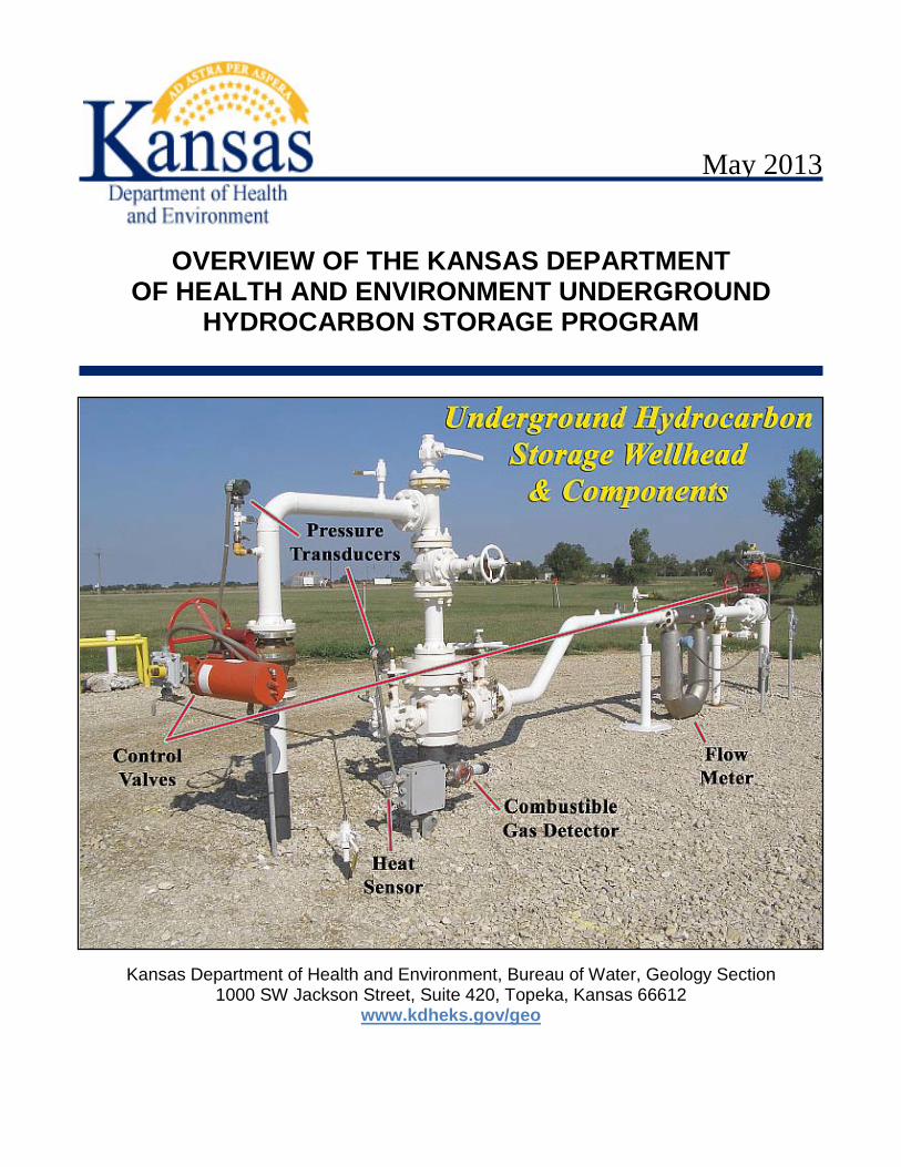
OVERVIEW OF THE KANSAS DEPARTMENT OF HEALTH AND ENVIRONMENT UNDERGROUND
HYDROCARBON STORAGE PROGRAM
Kansas Department of Health and Environment, Bureau of Water, Geology Section 1000 SW Jackson Street, Suite 420, Topeka, Kansas 66612
www.kdheks.gov/geo
This document is for use only as an overview of part of the Kansas Department of Health and Environment (KDHE) Underground Hydrocarbon Storage (UHS) Program. It is not intended to be an all inclusive listing of requirements or conditions for underground hydrocarbon salt cavern storage wells and associated brine storage ponds. This document may not be used in a court of law. Many of the requirements listed have been taken from the official Kansas Administrative Regulations publication. The permit application, permits, policies, guidance, statutes and rules and regulations establish the specific requirements for UHS wells and associated brine storage ponds and are available from KDHE or at http://www.kdheks.gov/uhs/index.html. INTRODUCTION The use of caverns solutioned in the salt deposit for storage of hydrocarbons began in the early 1950s. The underground storage of liquefied petroleum gas (LPG) and natural gas (NG) is beneficial for many reasons. The underground storage facilities allow for the storage of surplus hydrocarbon products during periods of low demand and provide availability of these products during periods of high demand. The storage of pressurized hydrocarbon products underground is much more economical than the surface storage of these products in high pressure containers, and many of the hazards of above ground storage are eliminated. Currently, KDHE administers three sets of regulations for underground storage of hydrocarbons. These are liquefied petroleum gas, natural gas, and crude oil. LPG storage facilities are the only type currently permitted and active in Kansas. WHAT IS LPG? LPG is defined as those hydrocarbons which are gaseous at normal atmospheric pressure, but may be condensed to the liquid state at normal temperature by the application of moderate pressures. Although normally used as gases, they are stored and transported as liquids under pressure for convenience and ease of handling. LPG is primarily a mixture of propane and butane, with a small percentage of other hydrocarbons, including propylene, butylenes, ethane, and natural gasoline. These products are stored in liquid form in underground salt caverns in Kansas. Several of the Kansas underground hydrocarbon storage facilities are located adjacent to fractionation plants, which separate raw LPG from pipelines or storage into separate components. Figure 1 depicts in general how a fractionation plant functions. HOW STORAGE OPERATES The LPG storage facilities in Kansas take product from pipelines and store it underground in caverns, created by dissolving naturally occurring beds of rock salt with water. The product is stored at pressures high enough to keep the product in liquid form in the caverns. The transfer of product into and out of the caverns is done using brine. Prior to transferring product into a salt cavern, the cavern is filled with salt saturated brine. Saturated brine is used so that the water will not dissolve more salt, enlarging the cavern. The cavern must be kept full of fluid,
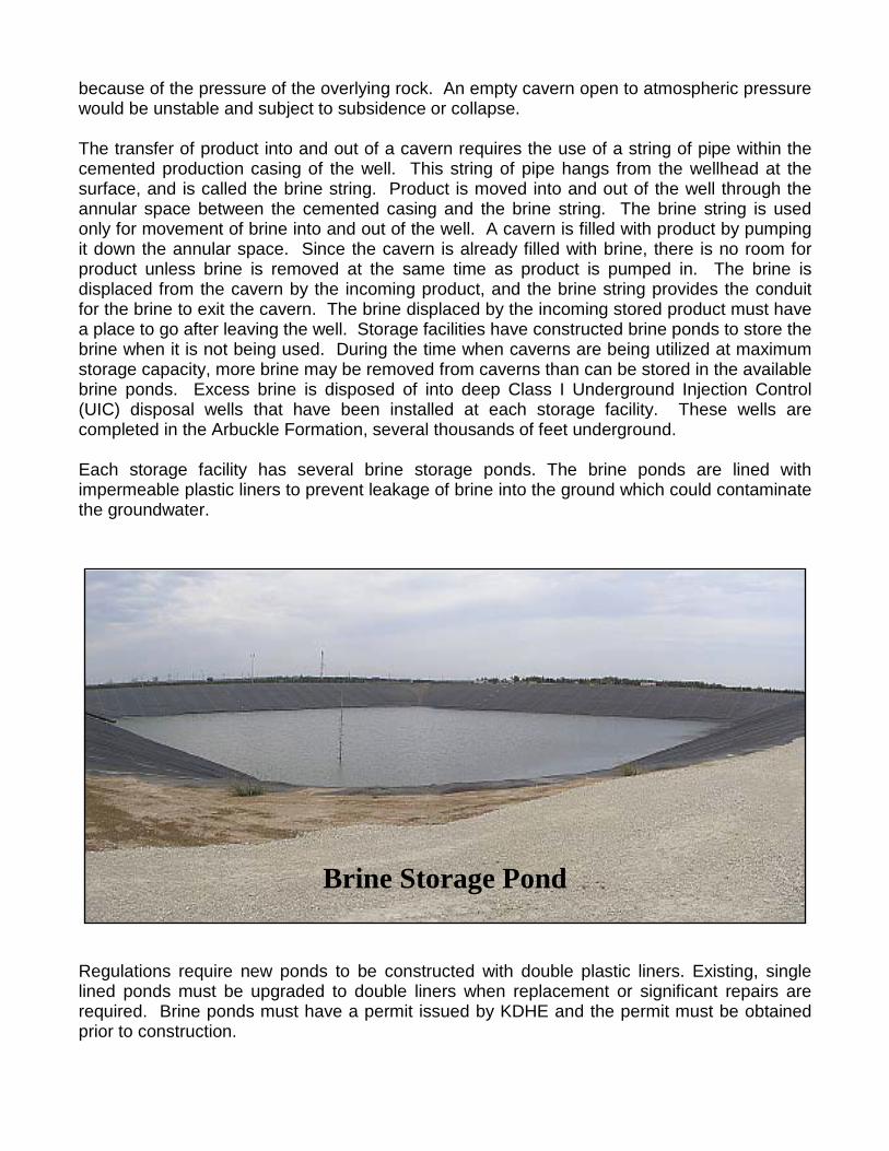
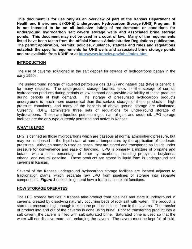
because of the pressure of the overlying rock. An empty cavern open to atmospheric pressure would be unstable and subject to subsidence or collapse. The transfer of product into and out of a cavern requires the use of a string of pipe within the cemented production casing of the well. This string of pipe hangs from the wellhead at the surface, and is called the brine string. Product is moved into and out of the well through the annular space between the cemented casing and the brine string. The brine string is used only for movement of brine into and out of the well. A cavern is filled with product by pumping it down the annular space. Since the cavern is already filled with brine, there is no room for product unless brine is removed at the same time as product is pumped in. The brine is displaced from the cavern by the incoming product, and the brine string provides the conduit for the brine to exit the cavern. The brine displaced by the incoming stored product must have a place to go after leaving the well. Storage facilities have constructed brine ponds to store the brine when it is not being used. During the time when caverns are being utilized at maximum storage capacity, more brine may be removed from caverns than can be stored in the available brine ponds. Excess brine is disposed of into deep Class I Underground Injection Control (UIC) disposal wells that have been installed at each storage facility. These wells are completed in the Arbuckle Formation, several thousands of feet underground. Each storage facility has several brine storage ponds. The brine ponds are lined with impermeable plastic liners to prevent leakage of brine into the ground which could contaminate the groundwater. Regulations require new ponds to be constructed with double plastic liners. Existing, single lined ponds must be upgraded to double liners when replacement or significant repairs are required. Brine ponds must have a permit issued by KDHE and the permit must be obtained prior to construction.
Brine Storage Pond
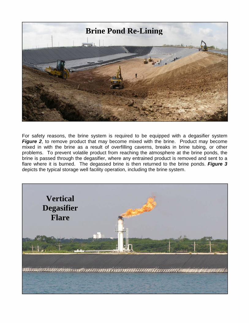
For safety reasons, the brine system is required to be equipped with a degasifier system Figure 2, to remove product that may become mixed with the brine. Product may become mixed in with the brine as a result of overfilling caverns, breaks in brine tubing, or other problems. To prevent volatile product from reaching the atmosphere at the brine ponds, the brine is passed through the degasifier, where any entrained product is removed and sent to a flare where it is burned. The degassed brine is then returned to the brine ponds. Figure 3 depicts the typical storage well facility operation, including the brine system.
Brine Pond Re-Lining
Vertical Degasifier
Flare
CAVERN DEVELOPMENT Caverns are created in the bedded salt deposits by dissolving the salt with fresh water or unsaturated brine. The process is begun by drilling a hole from the surface down into the salt-bearing formation. This may require a bore hole in excess of 1,000 feet deep. As the well is drilled, several strings of steel casing are set into the well. The shallowest casing string, installed from the surface to below the occurrence of any fresh groundwater, is called the surface casing. It is typically a few hundred feet in length, and is cemented to the formation from bottom to top. The well is then drilled through shale bedrock into the Wellington salt, and another string of steel casing is cemented in place, at least 100 feet below the top of the salt. For safety reasons, regulations require a second string of full-length steel casing be installed and cemented within the first string, providing double casing protection throughout the entire well. This double casing requirement only applies to newly permitted and constructed wells. However many of the existing wells have had a liner installed to give the well this double casing protection. After the final casing has been cemented, drilling is continued through the interval of salt to be developed for caverns. This part of the hole is not cased. After the pilot hole is drilled the desired depth into the salt, another string of pipe is run into the open hole, called the tubing string or wash string. The tubing string is not cemented in the well but is suspended from the surface wellhead. Water is injected into the tubing string and this water dissolves the salt formation, creating the cavern over many months of circulation. The saturated brine created from dissolving the salt is returned to the surface in the annular space between the tubing and cemented casing. Figure 4 shows a typical storage well design. Sonar surveys are conducted periodically during the solution mining process to check on cavern development Figure 5 is an example of a sonar survey for a cavern. Fully developed caverns average approximately 200,000 barrels in volume. GEOLOGY OF KANSAS SALT STORAGE CAVERNS All of the solution mined storage caverns in Kansas are developed in the Hutchinson Salt Member of the Wellington Formation. The Wellington is Permian in age (about 275 million years old), and may be as much as 700 feet thick in central Kansas. The Wellington consists of two main units. The upper unit of mostly shale and silty shale, red and gray in color, is about 300 feet thick. It is underlain by the Hutchinson Salt Member, which ranges from 200 to 600 feet thick and generally consist of beds of halite (salt) interbedded with gray shale and anhydrite. The Hutchinson Salt Member contains about 60-80% salt in Kansas (Ratigan and others, 2002). The thickest layers of salt tend to be found in the lower part of the member. It underlies an area of about 37,000 square miles in the subsurface of central and south-central Kansas (KGS, 2002). The roughly circular shape of the extent of the Hutchinson Salt in Figure 6 reflects the fact that it was deposited in a subsiding basin, with the salt thickest near the center and thinning toward the edges. The boundary of the Hutchinson Salt is a depositional boundary except on the east side, where the edge of the salt has been removed by dissolution by groundwater. The Permian bedrock in central Kansas generally dips gently to the west at about 15-20 feet per mile. In the area where underground storage caverns are developed, the top of the Hutchinson Salt Member is as shallow as 400 feet in the Conway area just west of McPherson, to about 950 feet deep at Bushton in Ellsworth County. Although the Wellington and other bedrock formations dip to the west in central Kansas, the ground surface generally slopes the
opposite direction, from west towards the east. As a result, erosion of rocks above the Wellington has caused the rocks exposed at the surface to be progressively older from west to east across the area. At Bushton, for example, the Wellington is overlain by about 300 feet of the Ninnescah Shale, also of Permian age. The Ninnescah consists primarily of red and gray shale, silty shale, and siltstone, with some gypsum. The Ninnescah is overlain by the Kiowa Formation and the Dakota Formation, both Cretaceous in age. The Dakota, consisting of interbedded sandstone and shale, is the near-surface bedrock unit at Bushton. Further to the southeast, in the direction of the storage facilities at Conway and Hutchinson, the bedrock units overlying the Wellington have been successively removed by erosion. At Conway, a few miles west of McPherson, the Wellington is overlain by only an incomplete section of Ninnescah Shale, which thins progressively eastward until it is missing completely just to the east of the Conway storage facilities. Interaction of fresh water with the salt beds in the Wellington has caused the salt to be dissolved, creating void space in the bedrock. Collapse of the overlying insoluble shale beds has resulted in a topographic low which has been filled with sand and gravel deposits by surface streams. The sand and gravel-filled channel forms part of an extensive fresh water aquifer system which extends from McPherson south to Wichita. Beginning in the 1950’s, solution-mined caverns developed in the salt were utilized for storage of liquid hydrocarbons (LPG) and natural gas. Caverns in the salt are well suited for storage of LPG and natural gas because the salt is essentially impervious to liquid and gas, has a compressive strength comparable to concrete under the pressure of the overlying rock, and because salt has “self-healing” properties. The salt is self-healing because salt, under pressure, slowly flows or creeps, and any fracture or void that may occur will re-seal itself over time. Figures 7 through 12 provide information concerning the hydrogeology relevant to the salt formation and the storage of hydrocarbons in the salt deposit. PRESSURE CONSIDERATIONS One factor that must be considered in locating storage caverns within the Hutchinson Salt is that the overburden pressure must be sufficient to contain the products at the pressures they must be stored. LPG, which is a gas at normal surface conditions, is stored underground at pressures high enough that the product is in a liquid state. Natural gas, however, is stored as a gas, and is stored under pressure in order to store more product in a given cavern volume. In general, the overburden pressure increases with depth at about 1 psi per foot. The pressure required to keep the product liquid varies with the composition of the product stored. For example, propane must be kept at a pressure in excess of 122 psi at a temperature of 70o F to be stored as a liquid. Ethane requires a higher pressure of 543 psi at a temperature of 70o F to remain liquid. As mentioned above, because of the westerly dip of the bedrock, the Hutchinson Salt Member becomes progressively deeper from east to west. Because of the pressures required to keep them in the liquid state, some products cannot be stored in caverns developed in areas where the salt beds are shallow.
MAXIMUM ALLOWABLE OPERATING PRESSURE (MAOP) As discussed previously, the weight of the rock above a storage cavern exerts a pressure of approximately 1 psi per foot of depth below the land surface. Pressure within the storage cavern must not be allowed to exceed the overburden pressure to avoid fracturing the surrounding rock and losing the structural integrity of the cavern. In order to prevent overpressuring of storage caverns, regulations limit the maximum pressure at which the product can be stored to a value less than the pressure that may fracture the surrounding rock. The maximum allowable operating pressure (MAOP) must not exceed 0.8 psi per foot of depth measured at the base of the cemented casing for LPG storage wells. The gradient of 0.8 psi per foot is allowed only for wells that have continuous pressure monitoring at the wellhead. If the well is not equipped for continuous pressure monitoring, then 0.75 psi per foot is the MAOP. The MAOP for natural gas storage wells is also 0.75 psi per foot. KDHE REGULATORY HISTORY Regulations for underground hydrocarbon storage wells were first promulgated by KDHE in 1981 after several incidents occurred, including the blowout of propane southeast of Hutchinson and the release of propane into the shallow aquifer beneath Conway, Kansas. The later incident resulted in property damage, contamination of water supplies and posed a significant safety risk. As a result of these incidents KDHE developed some basic regulations for UHS wells. These included a gamma-density log to monitor salt roof thickness, sonar based on cavern capacity, annual summary of storage pressures and groundwater monitoring. In January 2001, a significant incident occurred. A natural gas storage well located at the Yaggy storage facility experienced a casing leak releasing pressurized natural gas into a shallow subsurface zone through which the gas migrated under pressure for a distance of approximately seven miles southeast to beneath the City of Hutchinson. The pressurized gas then surfaced through unplugged legacy abandoned brine wells. This resulted in numerous injuries and two deaths, destruction of property due to fire and explosions and contamination of soil from brine ejected onto the groundsurface from some of these brine wells. As a result of this incident, the Kansas Legislature held several public hearings that year, including testimony from citizens, experts, industry and government agencies and the City of Hutchinson. The Legislature determined stringent regulations for the underground storage of hydrocarbons were necessary. As a result, the Legislature passed Kansas Statute Annotated K.S.A. 565-1,117. This statute instructed and authorized KDHE to develop regulations for the safe and secure storage of hydrocarbons in salt caverns for the purpose of protecting the public health, safety, property and the environment. KDHE worked with the industry and numerous experts to develop regulations that were well thought out which would accomplish the intended goals of the Legislature. KDHE held public hearings and established a public comment period for the proposed regulations to receive input, information and testimony to ensure the development of appropriate protective regulations. Temporary regulations were implemented in April 2003, with the final regulations becoming effective on August 8, 2003. In 2008 the Kansas Legislature instructed KDHE to develop regulations for the storage crude oil.
CURRENT REGULATORY REQUIREMENTS The Article 45, 45a and 45b regulations governing the permitting, construction, operation, monitoring, testing, financial assurance and plugging for LPG, Natural Gas, and Crude Oil storage facilities respectively. These regulations can be found at http://www.kdheks.gov/uhs. INVENTORY There are nine active LPG storage facilities in the state. Previously, one facility was used for storing natural gas, but that facility is no longer active and is in monitoring status. The active LPG storage facilities are indicated in Figure 13 with the exception of ONEOK Yaggy, this is the NG storage facility in monitoring. There are 382 active LPG storage wells with a total storage safe and secure capacity of approximately 73 million barrels. There are 94 wells in monitoring status. There are 46 active brine storage ponds with a total storage capacity of 36.8 million barrels. Forty-three of the ponds have double liners and 3 have single liners. The facilities that have single liner ponds have indicated they plan in the near future to double line these ponds. PLUGGING AND ABANDONMENT Upon the end of the useful life of an underground hydrocarbon storage well, the KDHE regulations require the well to be properly plugged to protect the public health, safety and the environment. Figure 14 depicts a typical well plugging. c/uhs section/UHS_Overview_2013_FINAL

FIGURES
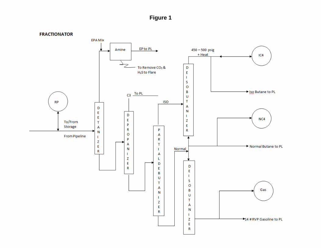
Figure 1
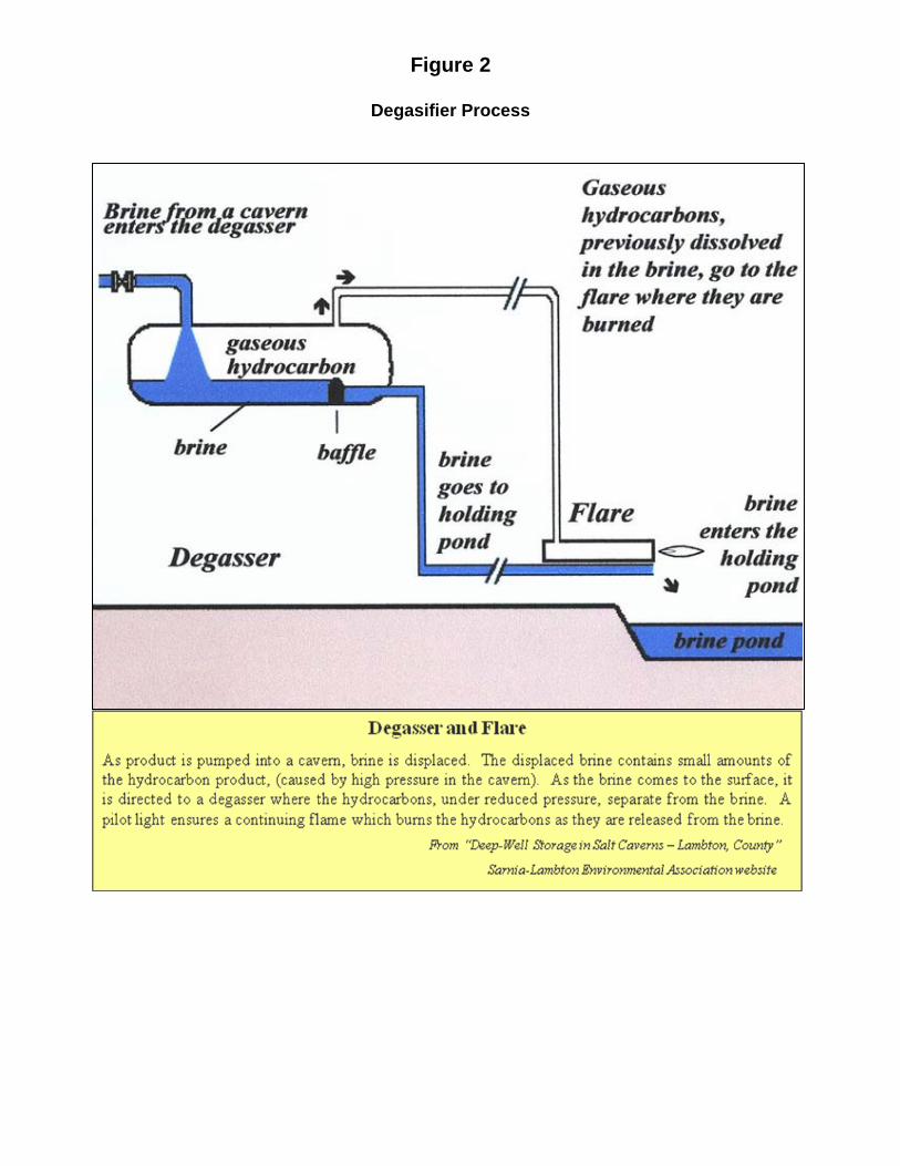
Figure 2
Degasifier Process
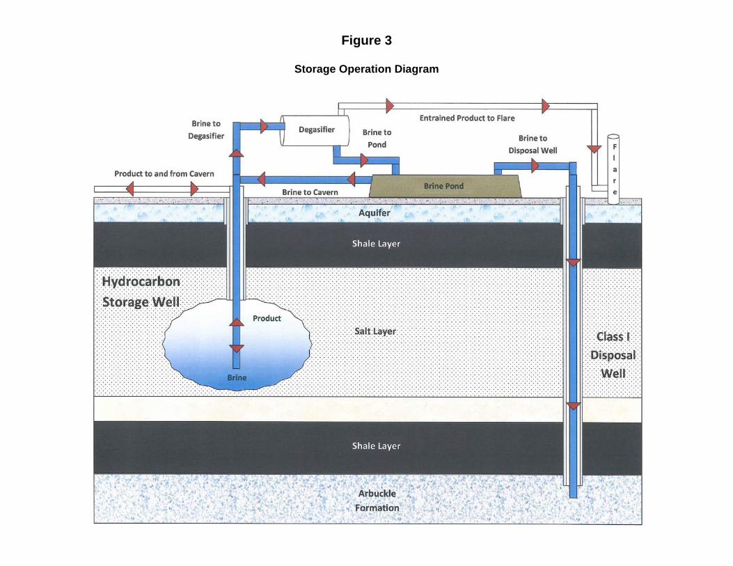
Figure 3
Storage Operation Diagram
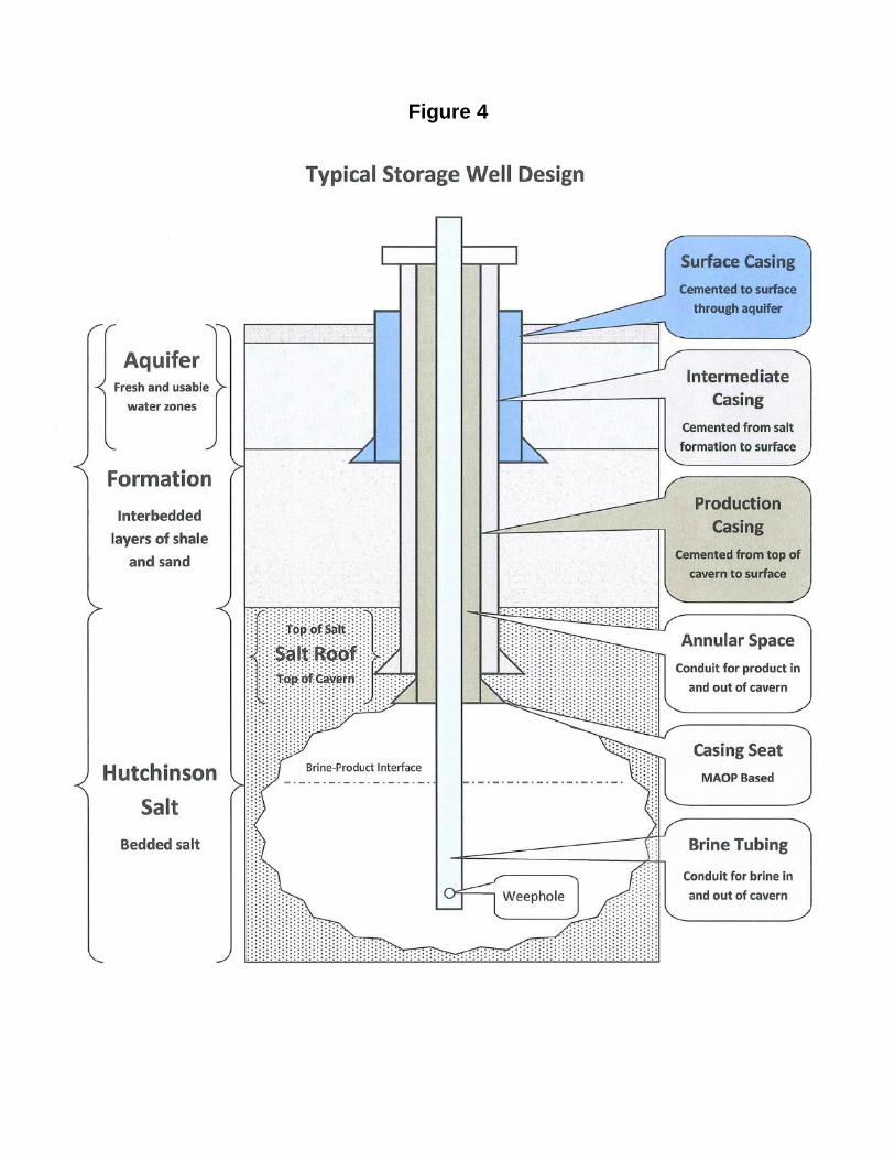
Figure 4
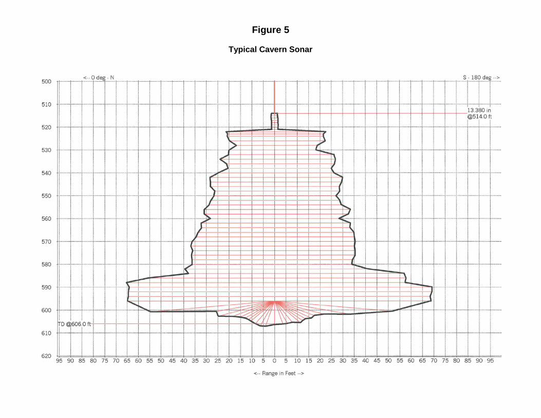
Figure 5
Typical Cavern Sonar
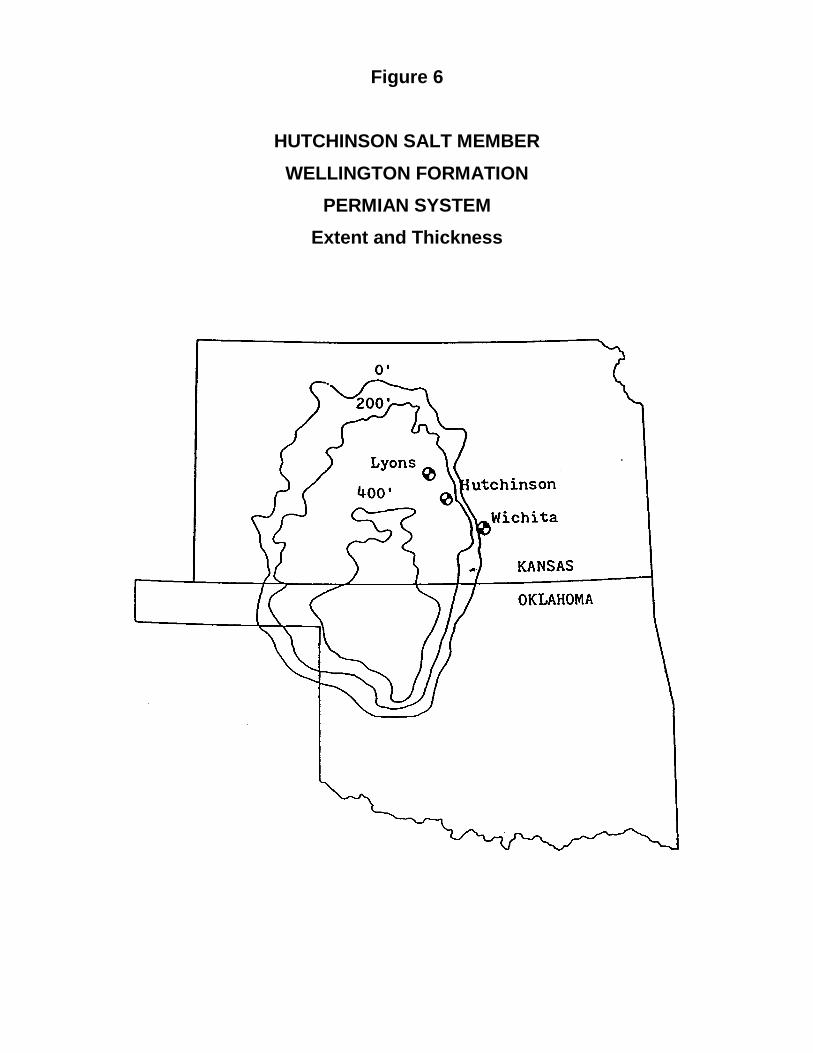
Figure 6
HUTCHINSON SALT MEMBER WELLINGTON FORMATION
PERMIAN SYSTEM Extent and Thickness
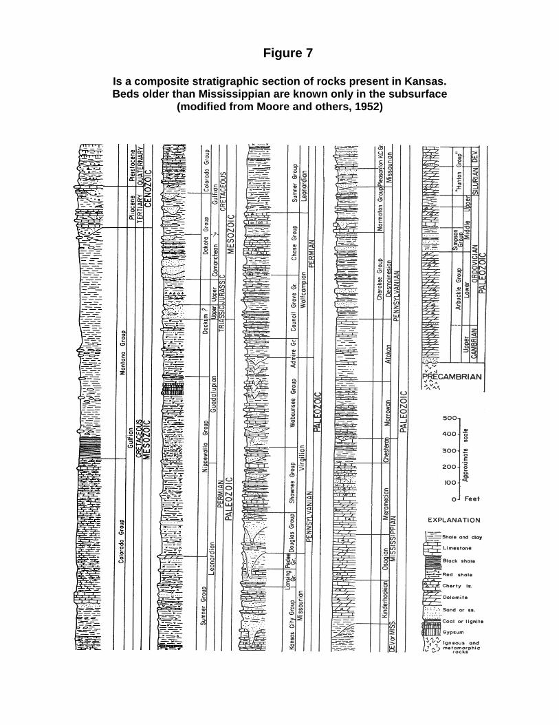
Figure 7
Is a composite stratigraphic section of rocks present in Kansas. Beds older than Mississippian are known only in the subsurface
(modified from Moore and others, 1952)
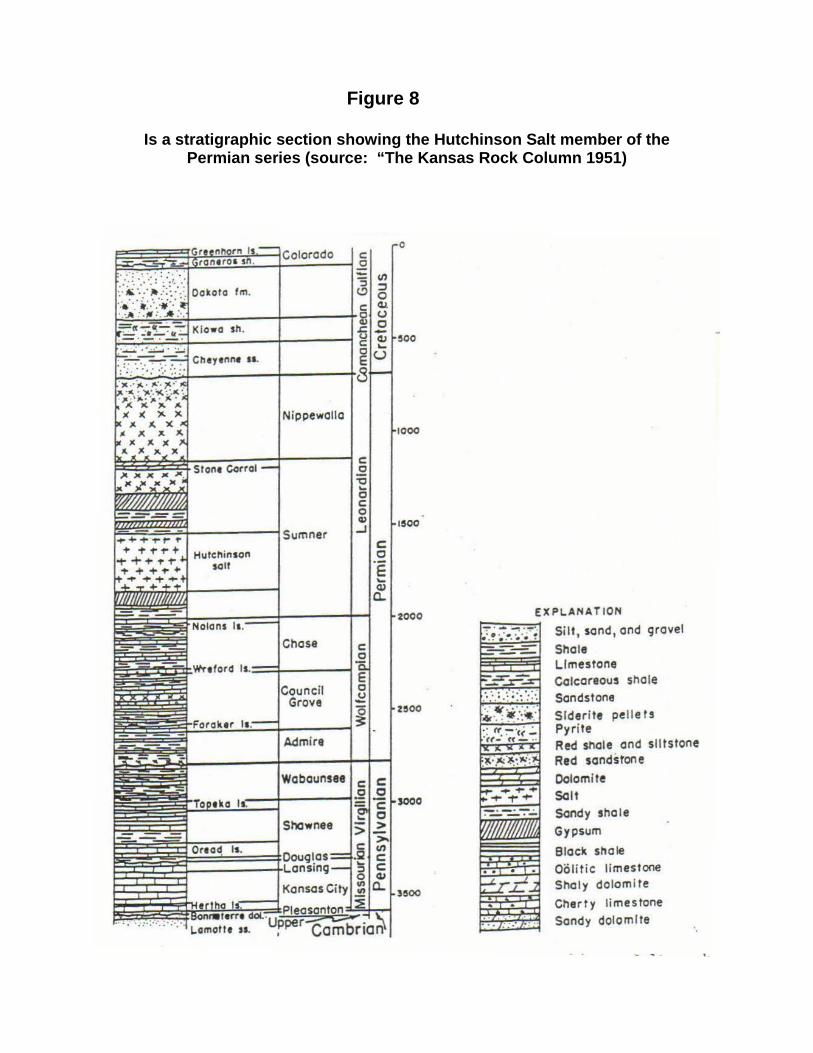
Figure 8
Is a stratigraphic section showing the Hutchinson Salt member of the
Permian series (source: “The Kansas Rock Column 1951)
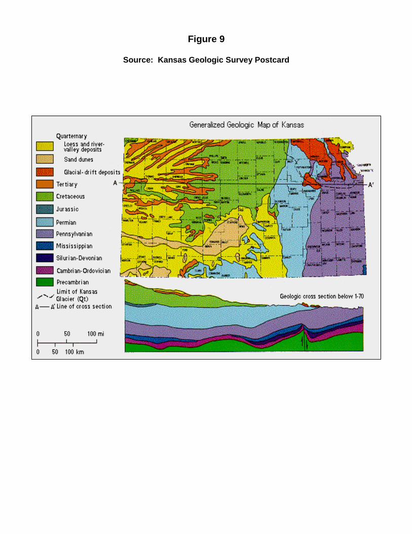
Figure 9
Source: Kansas Geologic Survey Postcard
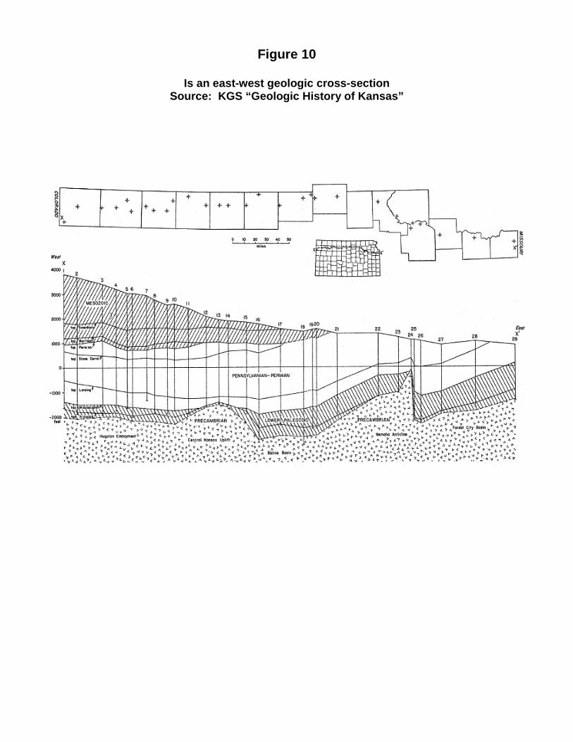
Figure 10
Is an east-west geologic cross-section Source: KGS “Geologic History of Kansas”
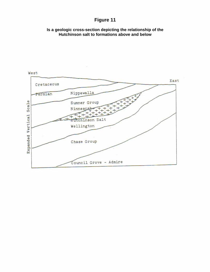
Figure 11
Is a geologic cross-section depicting the relationship of the Hutchinson salt to formations above and below
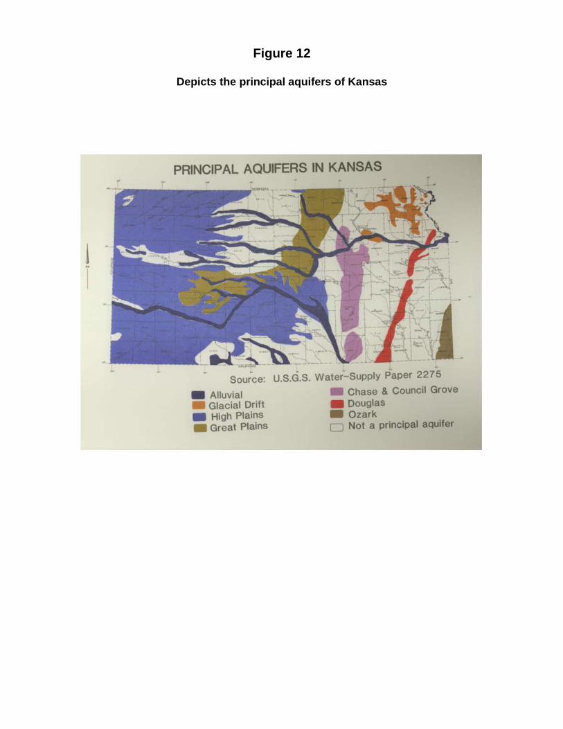
Figure 12
Depicts the principal aquifers of Kansas
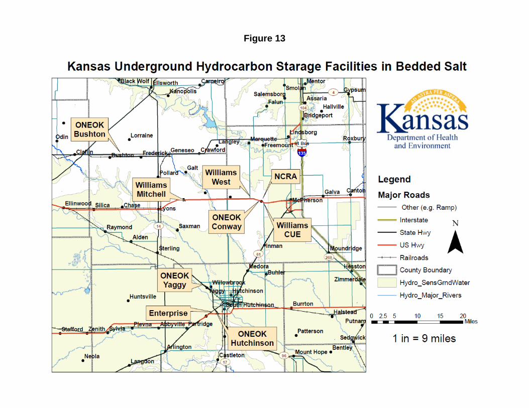
Figure 13
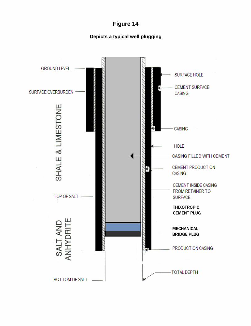
Figure 14
Depicts a typical well plugging
THIXOTROPIC CEMENT PLUG
MECHANICAL BRIDGE PLUG