an overview of the mil-hdbk-5 programthe analysis and presentation of data for mil-hdbk-5....
TRANSCRIPT
AFWAL-TR-84-4123
AN OVERVIEW OF THE MIL-HDBK-5 PROGRAM
PAUL E. RUFFBATTELLE COLUMBUS LABORATORIES505 KING AVENUECOLUMBUS, OHIO 43201-2693
SEPTEMBER 1984
FINAL REPORT FOR PERIOD 9 JUNE 1980-2 JULY 1984'.L.J
Approved for public relese.: distribution unlimited. "Q T E
N IOV I 184 .Reproduced From
Best Available Copy
MATERIALS LABORATOkYAIR FORCE WRIGHT AERONAUTICAL LABORATORIESAIR FORCE SYSTEMS COMMANDWRIGHT-PATTERSON AIR FORCE BASE, OHIO 45433.
84 11, 05 11

NOTICE
When Government drawings, specifications, or otk.er data are usedfor any purpose other than in Connection with a definitely related Governmentprocurement operation, the United States Government thereby incurs no respon-sibility nor any obligation whatsoever; and the fact that the Governmentmay have formulated, furnished, or in any way supplied the said drawings,specifications, or other data, is not to be regarded by implication orotherwise as in any manner licensing the holder or any other person orcorporation, or conveying any rights or permission to manufacture, use,or sell any patented invention that may in any way be related thereto.
This report has been reviewed by the Office of Public Affairs(ASD/PA) and is releasable to the National Technical Information Service(NTIS). At NTIS, it will be available to the general public, includingforeign nations.
This technical report has been reviewed and is approved for publi-cation.
C. L. Harmsworth, Technical Managerfor Engineering and Design Data
Materials Engineering BranchSystems Support DivisionAir Force Wright Aeronautical,Laboratory
FOR THE COMMANDER
T. . Reinhart, ChiefMaterials Engineering BranchSystems Support Division;Air Force Wright Aeronautical Laboratory
If your address has changed, if you wish to be removed from ourmailing list, or if the addressee is no longer employed by your organization,please notify AFWAL/MLSA, WPAFB, OH 45433, to help us maintain a currentmailing list.
Copies of this report should not be returned unless return isrequired by security considerations, contractual obligations, or noiceon a special document.
I." "• '.','-'":"." "" "•""." "" "-''," '.• •.",." "'-'.--•. .-•. • ,.'.". • " ............................"....-.".........."..".."......'.'....--'.'..-.o" ." ,• " e QI -- e m• • . • " " • - • • • " "q• "• •. " " ." .

UnclassifiedSECURITY CLASSIFICATION OF THIS PAGE W"00 Vote gored).
PAGE READ INSTRUCTIONSREPORT DOCUMENTATION PAEDEFORE COMPLETING FORMIa.RPORT NUMBER S 0TA;1"O .'1CTLGNME
AFWAL-TR-84-1423 I ~ TgESoO EIONSCTLGNNE
4. TITLE (men Su41It'd) S. TYPE or REPORT 6 PERIOD COVERED
AN OVERVIEW OF THE MIL-HDBK-5 PROGRAM Fnl ue9 90July 2, 1984G. PERFORMING 0011G. REPORT NUMBER
7. AUTHiON(s) S. CONTRACT OR GRANT NUM11ER~s)
Paul E. Ruff F3361 5-80-5037
S. PERFORMING ORGANIZATION NAMIE AND ADDRESS 10. PROGRAM ELEMENT. PROJECT. TASK~AREA & WORK UNIT NUMBERSBattelle's Columbus Laboratories 21/12505 King AvenueColumbus, Ohio 43201
11. CONTROLLING OFFICE NAME AND ADDRESS It. REPORT DATE
Materials Lab, Air Force Wright Aeronautical Lab September 1984Air Force Systems Commnand IS. MUMBER OF PAGESWright-Patt~rsnn Air FnrqP Baqp- Ohin 45433 46
14. MONITORING AGENCY NAME II ADODRESS(it diffeewnt frm Controlling Officq) 1S. SECURITY CLASS. (of Mooe roe"t)
DCASMA, DaytonDefense Electronics Supply Center UcasfeBuilding 5, 1502 Wilmington Pike 16. DECLASSIFIIATION/ DOWNGRADING
Dayton, Ohio 45444 SNDL
S6. DISTRIBUTION STATEMENT (ofif tAi.rport)
Approved for public release; distribution unlimited.
17. DOST RISIUTION STATEMENT 191 theo bstoctened lotE Bloc "*.11 d0 ifferent ft og hPer?)
IS. SUPPLEMENTARY NOTES
19. KtEY WORDS (Cenihn. on t~uor** nts id !IneessryWHO Identdity by block ninober)
tensile yield strength bea~ing yield strengthtensile ultimate strength bearing ultimate strengthcompressive yield strength design allowablesshear ultimate strength -
20. ASSTRACT (Contirme o P~ow~er* aide it necoooyenw mE fd~it? by Weeks urNMI.)
This final report presents an verview of the MIL-HDBK-5 program includ-ing the history of the MIL-HDBK-5 Ha dbook. A test program to determine NIL-1108K-5 design allowable properties f r 17-4PH (111000) casting is alsodescribed.
DD ,~,1473 EDIIION@PFI NOV SIS OBSOLETE tn~si e -4
SECURITY CLASSIFICATION OF THIS PAGE (Whon~m Ea.fneterd)
N÷
FaEFACE
This .final report was submitted by Battelle's Columbus Laborato-
ries, 505 King Avenue, Columbus, Ohio 43201, under Contract F33615-80-
C-5037 with the Air Force Wright Aeronautical Laboratory, Wright-Patterson
Air Force Base, Ohio. Mr. C. L. Harmsworth (MLSE) was the laboratory project
monitor. This report covers the period June 9, 1980, through July 2, 1984.
This report was submitted by the author, Mr. Paul E. Ruff, in July, 1984.
Acce'ssion For1NTTS -- GRA&I ~D'YTC TAB 0 ]Ju:toification
By.
Distr.h. -on
AvailaoilityI CodoeiAv.L• zýu/,./or
Dir~t 3 pecial
do
iii C
. . . . . . . . . . .. . . .. . .C. . . . . . . . . . . . . .C C C C C. . . . . . . . . .. . . . . . . . . . . . . . . . . . . . . . C

TABLE OF CONTENTS
Page
INTRODUCTION . . . . . . . .1
DESCRIPTION OF NIL-HDBK-5 " . 1
MODE OF OPERATION . . . . . . . . .. 2
DATA ACQUISITION AND ANALYSES e 4
HISTORY . . . . . . . . . . 6
APPENDIX A . . . . . . . . . . . . . . . ... . . . . . .. . .. 14
APPENDIX B . . . . .. . . . . . . . . . . . . 18
APPENDIX Co'.... 21
o e o o o e o o o o o o o o o o o o e e o
LIST OF SY1BOLS
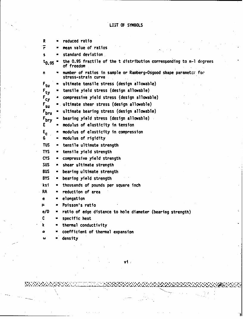
R = reduced ratio
F - mean value of ratios
s a standard deviationto.g5 - the 0.95 fractile of the t distrtbution corresponding to n-1 degrees
of freedomn f number of ratios in sample or Ramberg-Osgood shape paramet:T for
stress-strain curveFtu , ultimate tensile stress (design allowable)
Fty a tensile yield stress (design allowable)FC compressive yield stress (design allowable)Fysu ultimate shear stress (design allowable)
Fbru ultimate bearing stress (design allowable)
Fbr - bearing yield stress (design allowable)
E = modulus of elasticity in tension
Ec. a modulus of elasticity in compressionG modulus of rigidityTUS - tensile ultimate strength
TYS - tensile yield strength
CYS - compressive yield strengthSUS a shear ultimate strengthBUS * bearing ultimate strength
BYS a bearing yield strengthksi - thousands of pounds per square inchRA a reduction of area
e a elongationP a Poisson's ratio
e/D a ratio of edge distance to hole diameter (bearing strength)C = specific heatk S thermal conductivitya a coefficient of thermal expansion
w W density
vi:
V-
SUMVARY
L.n overview of the MIL-HDBK-5 program is presented. The intent
of the overvele is to provide information which will be helpful"to those who
are not familiar with the MIL-HDBK-5 program. In addition, the history of
the MIL-HDBK-5 Handbook and its predecessor, ANC-5 Bulletin, has been chroni-
cled for the first time.
MIL-HDBK-5, "Metallic Materials. and Elements for Aerospace Struc-
tures", contains standardized mechanical property design values and other
related design information for metallic materials, fasteners and Joints, as
well as other structural elements used in aircraft, missiles, and space vehi-
cles. The mechanical property design allowables are presented on a. statisti-
cal or specification basis$ Data for-other properties are-typica1,->rhe prod-
ucts included in the document are standardized with regard to composition
and processing methods and are described by industry or government specifica-tions. In addition, the Handbook contains some of the more commonly used
methods and formulas by which the strength of various structural elements
are calculated. The last chapter of the document contains guidelines for
the analysis and presentation of data for MIL-HDBK-5. Department of Defense
agencies, Federal Aviation Administration (FAA) and National Aeronautics and
Space Administration require the use of data in this Handbook in the design
of aerospace vehicles which are purchased or controlled by them
Although the Air Force has the responsibility for minNining and
updating MIL-HDBK-5, the Handbook .is maintained as a Joint effort of the Air
Force, Army, Navy, and FAA. The Air Force contracts with Battelle's Columbus
Laboratories to provide many of the services required to maintain and update
MIL-HDBK-5. Funding for the MIL-HDBK-5 program is currently provided by the
Air Force, Army Materials and Mechanics Research Center, and FAA. ..
Biannual MIL-HDBK-5 government/industry coordination meetings are
usually held in April and October. Representatives from governmental agen-
cies, aerospace industry, metallic material suppliers, and fastener wanufac-
turers attend these meetings. There is no formal membership. Currently,
Mr. C. L. Harmsworth, Materials Laboratory, Air Force Wright Aeronautical
Laboratories (AFWAL), chairs the MIL-HDBK-5 Coordination Group. The purpose
vii
S.
of these meetings is to consider and take action on proposed changes and addi-
tions to MIL-HDBK-5. Proposed modifications are normally attached to the
agenda for the meeting and presented orally at the meeting. The meeting also
provides the opportunity for anyane to propose or request changes to the Hand-
book. Various task groups, appointed by the Chairman, are utilized to study
specific problems and make recommendations to the MIL-HDBK-5 Coordination
Group. The additions and changes to MIL-HDBK-5 wi,ich are approved at the
coordination meetings are prepared by the*Air Force contractor in the form
of a typeset, camera-ready copy suitable for printing by the Naval Publica-
tions Lnd Forms Center.
Revisions of MIL-HDBK-5 are published, for the most part, annually.
Normally, three change notices (partial) revisions are issued followed by
a complete reissue. The Handbook is available from the Naval Publications
and Forms Center, 5C01 Tabor Avenue, Philadelphia, Pennsylvania 19120. Up
to ten copies will be supplied to government contractors at no cost.
A detailed description of the data acqdisition process, analyticaltechniques, and procedures for incorporating a new material or fastener into
MIL-HDBK-5 is included. As an example, a design allowable test program, con-
ducted on this contract, for 17-4PH (H10001) castings is described in detail
in Appendix C.
viii
/ . ,
vttt
I,,T•ODUCTIO,
The ANJC-5 Bulletit,, the predecessor to fMIL-HDOK-5, was originally
conceived in t'e late 1930's to standardize the requirements of various gov-
ernment agencies in the design of aircraft structure. As design concepts
and structural materials have evolved, there have also been evolutionary
changes in analysis procedures, presentation methods, the approval process
for changes and additions, and, of course, in the Handbook itself. While
the final reports for previous MIL-HDBK-5 contracts and interim reports,
such as reference (1), have described in detail the technical activities
performed to maintain and update the document, an overview of the MIL-HDBK-5
program has not been previously published. Such an overview is desirable,
specifically to inform new participants about the approval process, as well
as to orient them to the overall 1lIL-HDMK-5 program. In addition, inquiries
are continuously received concerning the procedure to be followed in gener-
ating data suitable for the determination of design allo'Yables and the data
required to incorporate new material into MIL-HDBK-5. The intent of this
overview is to provide information which will be helpful to those people
who are not familiar with the MIL-HDBK-5 program.A description of MIL-HDBK-5 and the mode of operation for the MIL-
HDBK-5 program has been included in this overview. The data acquisition pro-
ccdures and the analytical procedures have been described. A report on a
design allowable test program for 17-4PH (hlO00) castinqs has been attached
as Appendix C. In addition, historical background on the MIL-HDBK-5 program
has been incorporated.
DESCRIPTION OF MIL-HDBK-5
Since many aerospace companies manufacture both commercial and mili-
tary products, the standardization 0ý metallic materials design data which
(1) Rice, Richard, "Reference Document for Analysis of Creep and Stress-Rupture Data in MIL-HDBK-5", AFIJAL-TR-81-4097, Battelle's ColumbusLaboratories, September 1981.
\I

are acceptable to government procuring or certification agencies is very ben-
eficial to those manufacturers as well as governmental agencies. A:chough
the design requirements for military and commercial products may differ
greatly, the design values for the strength of materials and elements or other
needed material characteristics are often identical. Therefore, MilitaryHandoook MIL-HDBK-5, 'Metallic Materials and Elements for Aerospace Struc-
tures", contains standardized mechanical property design values and otherrelated design information for metallic materials, fasteners and joints, as
well as other structural elements used in aircraft, missiles, and space vehi-
cles. The Handbook lists the minimum strength values for those mechanical
properties which are widely used in the design of aerospace structures.
Information and data for other properties and characteristics, such as frac-
ture toughness strength, fatigue strength, creep strength, rupture strength,
crack growth rate, and resistance to stress corrosion are also included.The mechanical property design allowables are presented on a statistical or
specification basis. Data for other properties are typical. The productsincluded in this document are standardized with regard to composition and
.\ processing methods and are described by industry or government specifications.In addition, the Handbook contains some of the more commonly used methods
and formulas by which the strengths of various structural elements or compo-nents are calculated. The last chapter of the document contains the guide-lines for the analysis and presentation of data for MIL-HDBK-S. Department
of Defense agencies, Federal Aviation Administration (FAA), and National Aero-nautics and Space Administration require the use of the data on this Handbook
in the design of aerospace vehicles which are purchased or controlled by them.
MODE OF OPERATION
The Air Force has been assigned the responsibility for maintaining
and updating MIL-HDBK-5. However, the Handbook is maintained as a joint
effort of the Air Force, Army, Navy, and FAA. The Air Force contracts withBattelle's Columbus Laboratories to provide all of the services required tomaintain and update MIL-HDBK-5. The Air Force contractor (1) assesses the
2
: " " I~- t' J* " /
**.-,..C.# *..t.
design allowable data requirements of the aerospace industry, (21 collectsneeded data, (3) processes, computerizes, and stores collected data for anal-ysis, (4) statistically analyzes data to determine minimum or typical design
values, (5) prepares reports containing proposed additions and changes toMIL-HDBK-5, (6) participates in the biannual MIL-HDBK-5 government/industry
coordination meetings by arranging for meetings, preparing the agenda forthe meetings, and giving oral presentations of proposed additions and changes,as well as preparing the minutes of the meetings, and (7) prepares typeset,
camera-ready copy (suitable for printing) of the MIL-HDBK-5 revisions. Fund-ing for the MIL-HDBK-5 program is currently provided by the Air Force, ArmyMaterials and Mechanics Research Center, and FAA.
Biannual MIL-HDBK-5 government/industry coordination meetings areusually held in April and October. Representatives from governmental agen-cies, aerospace industry, metallic material suppliers, and fastener manufac-turers attend these meetings. There is no formal membership and the activity
is best described as a government/industry coordination group rather thana committee. The current chairman of the MIL-HDBK-5 Coordination Group isMr. C. L. Harnasworth, Materials Laboratory, Air Force Wright AeronauticalLaboratories (AFWAL). The purpose of these meetings is to consider andapprove proposed changes and additions to MIL-HDBK-5. Proposed modificationsare normally attached to the agenda for the meeting and presented orally atthe meeting. The meeting also provides the opportunity for anyone to proposeor request changes to the document.
The Chairman appoints task groups to stuly specific problems andto make recommendations to the MIL-HDBK-5 Coordination Group. Currently,there are two MIL-HDBK-5 task groups. The Fastener Task Group, which func-tions continuously, reviews proposals by fastener manufacturers for the incor-poration of design values for fastener systems into MIL-HDBK-5 and makes rec-ommendations to the Coordination Group concerning changes and additions toChapter 8 (fasteners) and Chapter 9 (guidelines). The objective of the Ele-vated Temperature Task Group, which has been operating for eight years, isto delineate the type of properties that engine manufacturers and other aero-space companies concerned with high-temperature applications would likeincluded in Ml.-HDBK-5, to determine the analytical methods to be used to
""3
analyze such data, and to prepare guidelines specifying the analytical proce-
dures and the methods of presenting such data in MIL-HDBK-5. The objective
of the Aluminum Casting Task Group, recently disbanded in May 1984, was to
incorporate statistically based design allowables for at least one high-
strength, premium-quality, aluminum casting alloy into MIL-HDBK-5. These
task groups provide invaluable service to the MIL-HDBK-5 program. p
The additions and changes to MIL-HDBK-5 which are approved at the
coordination meetings are prepared by tne Air Force contractor in the form
of a typeset, camera-ready copy suiteble for printing by the Naval Publica-
tions and Forms Center.Revisions of MIL-HDBK-5 are published, for the most part, annually.
Normally, three change notices (partial) revisions are issued followed by
a complete reissue. The Handbook 's available from the Naval Publications
and Forms Center, 5801 Tabor Avenue, Philadelphia, Pennsylvan4a 19120. Up
to ten copies will be supplied to government contractors at no cost.
DATA ACQUISITION AND ANALYSES
Because of the importance u0 the data acquisition and data analy-sis functions in maintaining MIL-HDBK-5, these activities are described inmore detail. A critical part of the MIL-HDBK-5 progran is the collectionof needed data. Aerospace companies end material suppliers provide a consid-erable ankiunt of data. Tensill yield and ultimate strength design values
are determined on a statistical basis. Consequently, large quantities oftest values from many different heats or lots from products of different sizesare required. Metallic material suppliers routinely conduct tensile testson production material, as part of their quality control procedures to deter-mine conformance to the sp.cified material specification. Most material sup-pliers c~operate in supplying this tensile property data for the determination
of statistically based design values for MIL-HDBK-5. Much data, especially
fatigue and creep data, are obtained from the open literature. An i..portantsource of data, available from published literature, is the Metals and Ceram-ics Information Center, which collects data for metallic materials. Another
4* -.* ~**. * ~ **. .* ~ ~~ * ~ **'.~*~".v*
important data source is the MIL-HDBK-5 files which are maintained by the
Air Force contractor. These files contain various types of data (some unpub-
lished) which have been supplied for exclusive use on the MIL-HDBK-5 program.
For new products it is usually necessary to conduct a test program
to obtain the required mechanical property data and other information required
to incorporate a new material into MIL-HDBK-5. In many instances, the company
which developed and markets the material conducts the test program to obtain
the required mechanical property data for the determination of design allow-
ables. In the past, the Air Force contractor, for the MIL-HDBK-5 program,
has conducted design allowable test programs to obtain needed data. Battelle
executed such a test program, which is described in Appendix C, on this con-
tract for 17-4PH (HlO00) castings. In other cases, when design values for
certain properties were missing from MIL-HDBK-5, the Materials Laboratory,
AFWAL, has performed limited test programs to acquire needed data. The Mate-
rials Laboratory, AFIUAL, Is currently sponsoring a research' program, "Manufac-
turing Technology Effects of Manufacturing Processes on Structural Allowa-
bles". This program, which Is performed by an Air Force contractor, generates
mechanical property and fatigue data suitable for the determination of design
values for MIL-HDBK-5. The fastener company which developed and/or markets
the fastener normally supplies the test data for a new fastener. Sect 4on
9.4.1.4.3 of Chapter 9 in MIL-HOBK-5 -equires.that 75 percent of assembled
Joint strength data be generated by one source and 25 percent from another
source. In some instances, fastener data have been generated by aerospace
companies, usually under government contract.
Section 9.1.6 of MIL-HDBK-5 specifies the data requirements for
a new material. This section has been excerpted from MIL-HDBK-5 and is
attached as Appendix B. Chapter 9 also contains the requirements for ele-
vated temperature, fatigue, crack growth, fracture toughness, and creep-
rupture data. Section 9.4.1 of MIL-Hf•K-5 delineates the data requirements
for a new fastener system. After the approval of static Joint strength allow-
ables for incorporation into MIL-HDBK-5, the fastener manufacturer must pro-.
vide forty samples of the fastener, from the same production lot as that used
In the test program, to the Chairman of the MIL-HDBK-5 Coordination Group
as specified in Section 9.4.1.7.3 of MIL-HDBK-5.
5
S• . ..... % • • ~~~~~~............ ... %• .%o.- -%.••. .o.....%"....." •x..- ..*.... •% il% l l*fi ""1. 1 I + .ll ll~l '." I+' *4 11¢i # l '4 I $ l ." . . • . •. . . . . '.*%* . . . . . . **__ + 1 1 • 1111 *1 1 I
Certain procedures must be followed for the Incorporation of a new
material or fastener in MIL-HDBK-5. Section 9.1.6 of MIL-HDBK-5 specifies
the procedure for new materials, while Section 9.4.1.7.1 of MIL-HOBK-5 delin-
eates the method for fasteners. These procedures must be followed by the
company (or organization) initiating action to incorporate design data in
MIL-HDBK-5 for their products.After collecticn of the required data, the data must be analyzed
in accordance with the procedures described in Chapter 9 of MIL-HDBK-5. These
guidelines provide detailed information concerning the data requirements and
,.ne analytical techniques to be employed in the analyses of various types
of data to determine minimum or typical design values. A description of the
various analytical methods has not been included because Chapter 9 of NIL-
HDBK-5 contains this information.
For metallic materials, the Air Force MIL-HDBK-5 contractor fre-
quently analyzes the test Oats to determine design allowables. Computers
are utilized to store and analyze data; consequently, these analyses can be
performed efficiently. As an example, Appendix C describes the analysis of
data for 17-4PH (H1000) castings performed by Battelle on this contract.For fasteners, the fastener manufacturer wt~imh inittatps action to incorpo-
rate design data for their product into MIL-HDBK-5 conducts the analysis.
The MIL-HDBK-5 Fastener Task Group reviews and approves the analysis of fas-
tener data to determine design allowables.
HISTORY
The history of the MIL-NDBK-5 Handbook and the ANC-5 Bulletin has
not previously been chronicled. Therefore, an effort has been made to record
the past history of these documents. Historical files were searched and theminutes of previous meetings and correspondence wore reviewed in an effort
to reconstruct previous gvents. However, early records were not diligentlymaintained, resulting in meager information in the years prior to 1948. For-
tunately, the files did contain most of the revisions of the MIL-HDBK-5 and
its predecessor. These revisions were most helpful in arranging the sequence
6
of events. Although the history, which follows, may not be complete, it is
believed that this description conveys a fairly accurate impression of thehistory of this Handbook. It is hoped that this history will prove interest-ing, especially for new participants who have just recently become involvedwith the MIL-HDBK-5 program.
The predecessor to MIL-HDBK-5 was the ANC-5 Bulletin. This docu-ment was prepared by the ANC-5 Subcommittee of the Army-Navy-Coimmerce Contit-tee on Aircraft Design Criteria and issued by the latter. So far as couldbe deteimined, the initial issue of this Bulletin occurred in 1937. Revisions
of ANC-5 were published in October 1940, December 1942, and October 1943.After the 1943 revision, the activity involving ANC-5 was discontinued untilthe close of World War II,
The ANC-5 Subcommittee was a part of the Army (Air Force)-Navy-Com-merce (Civil) Committee (ANC) on Aircraft Design Criteria. The function ofthis Committee was defined on March 19, 1946, as follows: "To develop air-craft design criteria governing strength, detailed design, propulsion systems,equipment, flight characteristics, and performance of cargo, trasasport, train-ing, and military aircraft; and to recommend the adoption of these criteriaby the three member branches of the government." The mission of this ANCCowuittee was carried out by sevEral subcommittees, called ANC-l, ANC-2,.P*..., through ANC-17. Later subcommittees, up to ANC-23, were added. ThesesuIcommittecs, with the exception of ANC-5 and those on materials, expiredfor unknown reasons. The ANC-5 Subcommittee continued to actively functionfor two major reasons: (a) The activity of the Subcommittee was fundamental;it was needed; and it did not impinge upon the freedom of industry to inno-vate, and (b) the Subcommittee was energetically supported by all concerned.
The first meeting of the ANC-5 Group after World War II was appar-ently on June 5, "'45, according to references. The next meeting was heldon May 2, 1946, at J attendees consisted of three members (two military andone civilian) from the Army (Air Material Command) and Navy (Bureau of Aero-nautics), two members from Civil Aeronautics Administration (CAA), and arecorder from the militAry (US.'s). The Chairman was Mr. E. I. Ryder, CAA.Five people from the Aluminum Company of America and Reynolds Metals also
7
attended this meeting. The Chairman stated at this meeting that it would
be desirable to have members of the aircraft industry present at the next
meeting and to encourage industry participation in future revisions of ANC-5.
Mr. William T. Shuler, CAA, succeeded Mr. Ryder as Chairman in 1947.
People from various government agencies, the aircraft industry, material sup-
pliers, and fastener suppliers attended the ANC-5 Meeting held on October 7,
1947, swellin, attendance to 37. The ANC-5 Committee meetings were held
alternately in Washington, D.C., and at Wright-Patterson Air Force Base
(Dayton), Ohio. Generaliy, these meetings were scheduled in the Spring and
Fall of the year. On September 21, 1948, the supervisory body for the ANC-5
Subcommittee was changed to the Munitions Board Aircraft Committee. However,
the function, operation, and membership of the ANC-5 Group remained essen-
tially unchanged. In September 1953, Mr. J. E. Dougherty, Jr., CAA, became
Chairman. The Munitions Board was abolished in 1954, but the ANC-5 Group
continued to function as usual.
In 1954, Battelle Memorial Institute (Battelle) was awarded a con-
tract by the Materials Laboratory, Wright-Patterson Air Force Base, Ohio,
to review the field of material-property-design criteria for metals used in
aircraft and missiles, and to bring up-to-date a compilation of design infor-
mation for the design of aircraft and missiles. Over the next several years,
Battelle published seven Wright Air Development Center technical reports which
contained design allowables and other pertinent information for incorporation
into ANC-5. Since this initial contract, Battelle has continuously served'
as the Air Force contractor to maintain and update ANC-5 and MIL-HDBK-5.
In August 1956, the Air Force was assigned the responsibility for
maintaining ANC-5. Mr. M. J. Crane, Aeronautical Standards Group (Navy and
Air Force), was named Secretariat for the ANC-5 Subcommittee on February 13,
1957.
In 1958 it was decided to publish the next revision as a military
handbook. Battelle prepared the initial draft. Military Standardization
Handbook MIL-HDBK-5, which superseded ANC-5, was published in March 1959.
Since the abolition of the Munitions Board in 1954, the ANC-5
.and MIL-HDSK-5 Committees had been charterless. In 1959 effort was initiated
to establish a Joint Committee of the Department of Defense and the Federal
8
, -. . . .. .• .• ,,. . .. • ,, .- ,. .-.. . ,. . ,. . . .•. - . -../.• • .•. .. .
Aviation Agency on 'Federal Aircraft Design Criteria*. This Joint Committee
would have been the governing body for the MII-HDBK-5 Committee. However,
the establishment of this Joint Committee was not promulgated.At the May 1959 MIL-HDBK-5 Meeting, Mr. J. E. Dougherty, Jr.,
resigned and Mr. E. S. Newberger, FAA, was appointed Chairman. Mr. Newbergerresigned in 1961 and Mr. D. A. Shinn, Aeronautical Systems Division (AirForce), became Acting Chairman for the November 1961 meeting. Mr. DeanLauver, FAA, assumed Chairmanship and presided at the MIL-HOBK-5 Meeting heidin May 1962. Mr. Lauver's Chairmanship was short lived and Mr. D. A. Shinn,Air Force, became the new Chairman. He presided at the meeting held inNovember 1962. Battelle began preparing the revisions and change notices
to MIL-HDBK-5 in 1964.Messrs. Donald P. Moon and Walter S. Hyler prepared a report, AFML-
TR-66-386, -MIL-HDBK-5 Guidelines for the Presentation of Data", dated Feb-ruary 1967. This report specified the analytical procedures and methodsfor presenting data for MIL-HDBK-5. Prior to that time, many differeitt proce-dures had been used. Certain procedures had been adopted either formally
.or informally. In some instances, the techniques had been fairly well docu-mented but were located variously in attachments to the minutes of previousMIL-HDBK-5 meetings, in statistical text and workbooks, in company reports,
or in other miscellaneous publications. For this guideline report, procedureswere written delineating these past practices. When necessary, analyticaltechniques wera developed. These guidelines represented an important mile-stone in the utilization of standardized procedures for the analysis and pres-entation of data for MIL-HDBK-5. This report contained all of the requiredinformation for the analy3is and presentation of data for MhIL-HDBK-5 in oneconvenient source. All of the procedures contained in these guidelines hadbeen previously approved by the MIL-HDBK-5 Group. These guidelines were later
"-A incorrorated into MIL-HDBK-5B, September 1971, as Chapter 9.
Beginning with the 39th MIL-HDBK-5 Meeting, April 1970, Battelleprepared and distributed the agenda and minutes of the MIL-HDBK-5 meetings.
At the 46th MIL-HDBK-5 Meeting, held in October 1973, Mr. D. A.
Shinn announctd that he would be retiring from the Air Force and that he was
9
Ii , \
stepping down as Chairman. Mr. C. L. Harmsworth, AFNL (Air Force), succeeded
Mr. Shinn as Chairman and presided at the 46th Ileeting.
Battelle prepared a "soft" metric conversion of the first seven chap-
ters of MIL-HDBK-5. This "soft" mnetric version of MIL-HDBK-5 was published in
an Air Force technical report, AFýIAL-TR-80-4110, "Metrication of MIL-HDBK-5C",
dated August 1980. Although this document was recognized to be limited in
its usefulness, the primary benefit of this effort was the revelation of prob-
lems associated with the conversion to metric design values and the presenta-
tion of matric design data. The experience gained from this "soft" conversion
will facilitate the preparation of a future metric version of MIL-HDBK-5 based
upon a "hard" conversion, when "hard" metric data become available.Beginning with MIL-HDBK-!5C, Change Notice 3, dated June 1981, the
revisions of MIL-HDBK-5 were typeset at Battelle, rather than by the Naval
"Publications and Forms Center. T:,is change was made to shorten the processing
time required to publish MIL-HDBK-5 revisions.
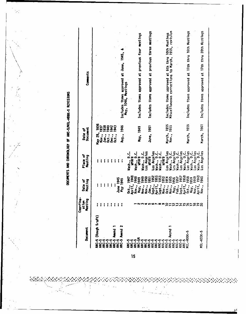
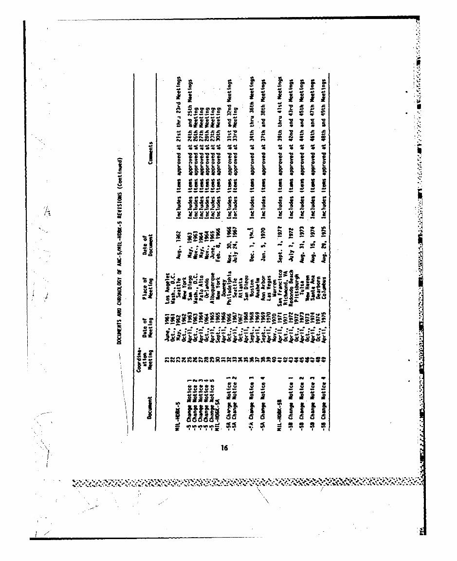
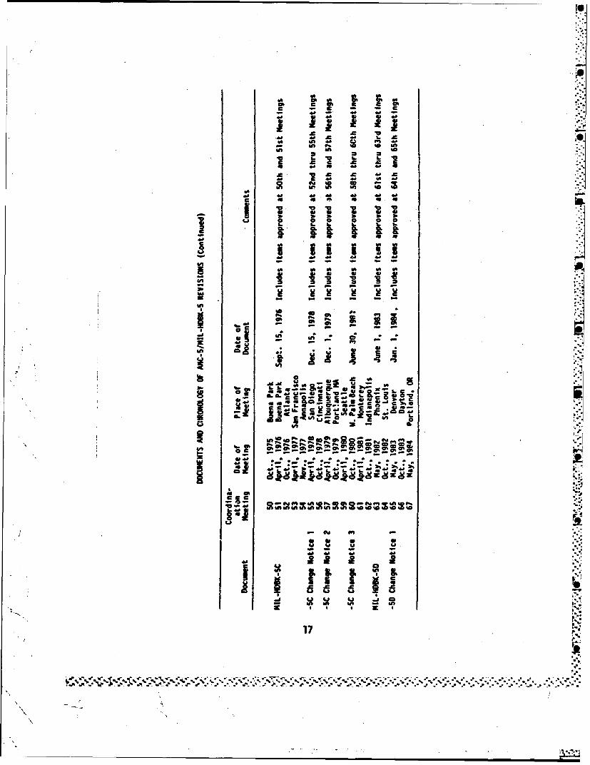
A chronology of the various meetings, meeting places, dates, and
ANC-5/MIL-HDBK-5 revisions are listed in Appendix A.
From a technical standpoiiot, some of the interesting changes and
highlights in the evolution of ANC-5 and MIL-HDBK-5 are described in the
following paragraphs.The 1938 version of ANC-5 contained design information for columns,
thin-walled sections mechanical property design values for wood, steel alloys,
alumnum alloys, and magnesium alloys, as well as design allowables for joints,
fittings, and parts. It is interesting to note that the chapter on wood was
deleted from ANC-5 in Amendment No. 2, dated August 1946.Elevated temperature design data for static strength properties
and creep data first appeared in ANC-5, dated December 1942. The method of
presenting creep data was changed to utilize a nomograph which first appeared
in MIL-HDBK-5, Change Notice 5, dated June 1, 1965. New guidelines for anal-
yzing and presenting creep and stress-rupture data were approved at the 58thMeeting, October 1979, and the procedure appeared in MIL-HDBK-5C, ChangeNotice 3, dated June 30, 1981. This guideline changed the method of present-
ing creep and stress rupture data from a noý,'ograph to an illustration depict-
-! ing an isothermal plot of data in the form of stress versus time to produce
/1/
S~10
..................................
I..~ .- " /_______________________

a certain percent creep or rupture. Creep and rupture data analyzed in
accordance with these new guidelines were first approved for incorporation
into MIL-HDBK-5 at the 65th Meet'ng, May 1983, and the data appeared in MIL-
HDBK-SD, Change Notice 1, dated January 1, 1984.Rotating beam data in the form of S/N curves appeared in ANC-5,
dated March 1955. A recommendation by the Task Group on Fatigue that only
axial load fatigue data be incorporated into MIL-HDBK-5 and that data be pre-
sented in the form of S/N curves or constant-life diagrams was approved at
the 22nd Meeting, October 1961. Consequently, the incorporation of rotating
beam data was discontinued and existing rotating beam data were deleted from
the Handbook since there waslittle interest in this type of data by the users
of MIL-HDBK-5. Subsequent fatigue data incorporated into the Handbook was
in the form of constant-life diagrams. At the 61st Meeting, April 1981, a
recommendation was made to change the method of analyzing and presenting
fatigue data. This recommendation was approved and a change in the guidelines
was made in MIL-HDBK-50, dated January 1, 1983. The new technique involves
a statistical procedure for consolidating fatigue data by stress ratio andpresenting the resulting data in the form of computer-generated S/N curves.Most of the constant-life diagrams in MIL-HDBK-5 have been replaced with new
S/N curves.
Stress-strain and tangent-modulus data were first incorporated into
ANC-5, dated May 1949.The initial design information for titanium alloys was incorporated
into MIL-HDBK-5, dated March 1959.
Information on fracture toughness and typical KIC data was approvedfor incorporation into Chapter 1 of MIL-HDBK-5 at the 35th Meeting, April1968, and first appeared in MIL-HDBK-SA, Change Notice 3, dated December 1,
1968. After about 10 years of consideration and discussion, a guideline for
* jthe analysis and presentation of plane-stress and transitional fracture tough-ness data was approved for incorporation at the 44th Meeting, October 1972,
and first appeared in MIL-HDBK-5B, Change Notice 2, dated August 31, 1973.Residual strength data analyzed in accordance with the new guidelines were
approved at the 48th Meeting, October 1974, and first appeared in MIL-HDBK-5B,
Change Notice 4, dated August 29, 1975. The first KIC data analyzed in
11
S. . . . . : . .. . . . . . . .. . . . . . . . . -l. . . . . .. . . . . ,-

accordance with the new guidelines were approved at the 49th Meeting, April
1975, and appeared in MIL-HDBK-5B, Change Notice 4, dated August 29, 1975.AL the 44th Meeting, October 1972, agreement was reached to delete
column formulas from MIL-HDBK-5. In lieu of these equations, a basic column
formula was incorporated together with a brief discussion of column strength,and references to structural analysis methods for columns were added. Atthis same meeting, a change in the scope of the Handbook was approved. This
change indicated that information on element behavior will emphasize thosematerial characteristics needed to assist the design function and that methods
of structural analysis are not within the scope of the document. These twochanges appeared in MIL-HDBK-5B, Change Notice 2, dated August 31, 1973.
Guidelines for the analysis and presentation of fatigue-crack-prop-
agation data were approved at the 54th Meeting, November 1977. These new
guidelines, as well as the first fatigue-crack-propagation data, appearedin MIL-HDBK-5C, Change Notice 1, dated December 15, 1978,
Design information for the first product developed and marketedby a foreign supplier was incorporated into MIL-HDBK-5D via Change Notice 1,dated January 1, 1984. Design allowables for 7010-1773651 and -17651 platewere added to the Handbook. These products were produced by Alcan Plate Lim-ited, Birmingham, England. The material was fabricated and tested using met-ric units of measure. The metric mechanical property data were converted
to English units for analysis and inclusion in MIL-HDBK-5.With regard to future technical effort, the development of an ana-
lytical procedure for the determination of A and B values from a non-normaldistributio., (by utilizing the 3-parameter Weibull distribution) has been
completed and approval of the guideline is expected at the 68th Meeting,October 1984. Statistically based A and B values have been determined forA357-T6 castings; however, design values cannot be incorporated into MIL-HDBK-5 until a public specification describing these castings is published.A propesed Aerospace Materials Specification is being reviewed and is expected
to be published in the near future so that the first A and B values for cast-ings will soon appear in MIL-HDBK-5. A procedure for analyzing strain controlfatigue data has been developed. It is anticipated that a guideline procedurefor analyzing and presenting strain control fatigue data will be approved
12
.7 7 7-
for incorporation into MIL-HDBK-5 in 1985. With the adoption of a procedure
for analyzing populations witli skewed distributions, it should be feasible
to determine statistically based A and B KIC values for those products for
which statistical quantities of data are available. It is anticipated that
such a procedure will be developed and approved for incorporation into the
Handbook in 1985. With such a procedure, A and B Kkz values for fracture
tough materials can be published in MIL-HDBK-5. Design allowable test pro-
grams have been completed or are in progress for a considerable number of
new products. It is anticipated that design allowables will be incorporated
into MIL-HDBK-5 within the next two years for the following products: Ti-15V-
3Cr-3A1-3Sn (STA) sheet, Ti-15V-3Cr-3A1-3Sn (ANN) sheet, Ti-IOV-2Fe-3A1 (STA)
die forging, 7050-T74513 extrusion, 7175-T7452 hand forging, 7175-T7452 die
forging, 15-5PH (HiOM5) plate, an(! 15-5PH (H925) casting. Much activity is
expected with the new aluminum alloys. It is anticipated that design allow-
ables for powder metallurgy (P/M) 7090-TTE71 extrusion and 7090-T7E75 die
forgings, as well as ingot metallurgy aluminum-lithium, will be incorporated
into the Handbook in the near future.At some future time, it is anticipated that the information in MIL-
HDBK-5 will be computerized so that the data can be stored and transmitted
electronically.
13
N i

APPENDIX A
CHRONOLOGY OF ANC-5/MIL-HDBK-5MEETINGS MNU REVISIONS
14
C
, ~ ~ ~ ~ ~ a Go i IIAII
Ul 0% e-U ,,1'
CL CL too- 4D- . 4,, .,s
0I m 0 O 0 01. C, U. ,,, I, f,- cu I-.
06 CL CL ~ 061 06
40 m 0 M. m
• I- 4 , -) • 80-- , .
VI. 0hII. 4, "• -- " .
#A &A LA 4
00 0n in4,
- - _,1"
41. da Im
me, 0.h a%80
MO 41 ,L
4, 4, 4, =o 4, , 4c -C 0 0- C a C
Ccin &4 t A0l6m V M6 M 6AU A00L
4=0 008 a #a C0#0 a0 10 to0
3. 2.. 3. c. . 00 , 0. 0.t O 1 I 0.1 0. Q 0.LMO :
fn1 00 0 (0
c- C* in CIcm C,
to ~ ~ ME in %n MOO in &n& n i , %&n& ,& nu A n L n& n6
* ~ ~ ~ 2 01 CiCi - i C* 0 0 0
15 0)
~0 .- UJ.
C @1 SI C4 1 K 5 1 51
ov--ý - - - Aa q C 41 4V CL V¸A5 454 4D4 45 A a v C
". .0 45 & V. b £ £ £
Sf~i 45l1555154 0 55 1 '0 45. -l I. 45l 45s 415"
&A iJ *A 00 4 .1
• o 4 4I 4 41 41i45 U•Z LZZ XU 44 5 45 5 45 5
- 45I~~f~~.~E ~ fe sap @ 5 0 'o 44 4•4 4 0 0 (A to on 0 45 44 to 4- 4 4 go
L. iL I.L i. .i. LL, . .L 1 . . II . .I
IAAAn lagfi :9i t i
'YLS
44 at
U n
* q
S..... • ~~~.'.•.i. .. ,,.•... .:. . ...
60 as 'a a a a a
,-1 -,, - ,. *" -I Sl *i..I a.-...
N. 1.- $ -
Iiiii
s.016
* ~ ~ ~ ~ ~ ~ ~ z r* ***eZ -- x~~i
C C U
C - C C
I UUS S4 1 A& 4A 41
an f ~ w W 16CLSnS
101
to
qp at *
IC. ~ 1. 5
to - -j - -SSIJ I s.
- . v~ -1 Cca 31
uU.
c ~ ado 0aUDI g *
Ch jig~Uý F. .FS9
cc coU4m4 141 U Wmx~
rac s!~ -ý
a US
vi MAm40s M2M 0014 4 P'.
C-fta~n'P' WE~ aSO
~S4 O .S~i usI'. S
I 17

APPENDIX B
REOUIREMENTS FOR NEW MATERIALS TOt INP.URPORATElY INTO MIL-HUBK-5,
1 8;
S ':1}
I -•-
* .1'
I
18,1i~
le .iA
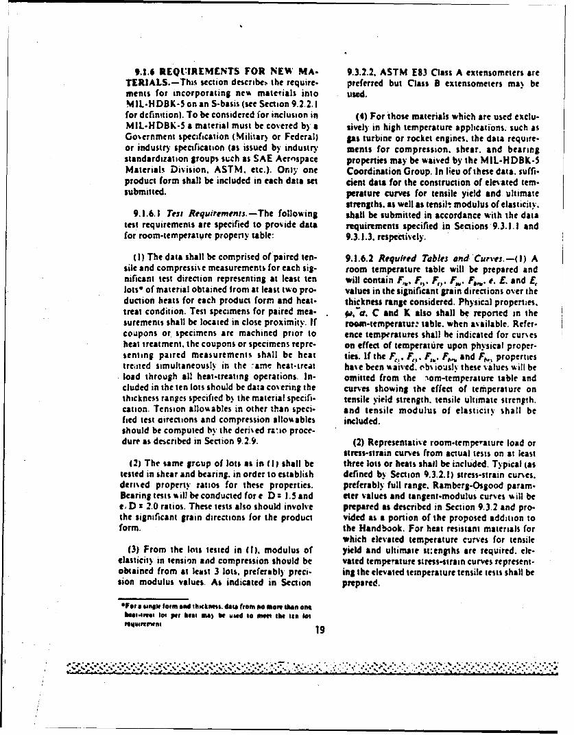
9.1.6 REQUIREMENTS FOR NEW MA- 9.3.2.2. ASTM E83 Class A extensometers areTERIALS.-This section describeN the require. preferred but Class B extensometers ma) bemints for incorporating new materials into used.MIL-H DBK-S on an S-basis (see Section 9.2.2.1for definition). To be considered ior inclusion in (4) For those materials which are used exclu-MIL-HDBK-5 a material must be covered b) a sively in high temperature applications, such asGovernment specification (Militar) or Federal) gas turbine or rocket engines, the data require-or industry specification (as issued by industry ments for compression. shear. and bearingstandardization groups such as SAE Aernspace properties may be waived by the MIL-HDBK-SMaterials Division. ASTM. etc.). Only one Coordination Group. In lieu of these data. suffi-product form shall be included in each data set cient data for the construction of elevated tem-submitted. perature curves for tensile yield and ultimate
strengths. as well as tensilt modulus of elasticity.9.1.6.1 Tesm Requirements.-The following shall be submitted in accordance with the data
test requirements are specified to provide data requirements specified in Sections 9.3.1.1 andfor room-temperature property table: 9.3.1.3. respectively.
(1) The data shall be comprised of paired ten- 9.1.6.2 Required Tables and Curves.--() Asile and compressive measurements for each sig- room temperature table will be prepared andnificant test direction representing at least ten will contain F,.. F . F,. F. F-,. e. Z. and E,lots* of material obtained from at least two pro- values in the significant grain directions over theduction heats for each product form and heat. thickness range considered. Physical properties.treat condition. Test specimens for paired men- . ,&a. C and K also shall be reported in thesurements shall be located in close proximity. If roem-temperatur: table, when available. Refer-coupons or specimens are machined prior to ence temperatures shall be indicated for cursesheat treatment, the coupons or specimens repre- on effect of temperature upon physical proper-senting paired measurements shall be heat ties. If the FF. F . F,, and F,,, propertiestredled simultaneously in the :ame heat-treat have been waived. eb iousli these values %ill beload through all heat-treating operations. In- omitted from the nora-temperature table andcluded in the ten lots should be data covering the curves showing the effect of temperature onthickness ranges specified b% the material specifi- tensile yield strength. tensile ultimate strength.cation. Tension allowables in other than speci- and tensile modulus of elasticity shall befied test directions and compression allow ables included.should be computed by the deri~ed ranio proce-dure as described in Section 9.2.9. (2) Representative room-temperature load or
stress-strain curves from actual tests on at least(2) The same group of lots as in (I) shall be three lots or heats shall be included. Typical (as
tested in shear and bearing, in order to establish defined b) Section 9.3.2.1) stress-strain curves.derised property ratios for these properties. preferably full range. Ramberg-Osgood param-Bearing tests will be conducted for e D : 1.5 and eter values and tangent-modulus curves will bee, D : 2.0 ratios. These tests also should involve prepared as described in Section 9.3.2 and pro-the significant grain directions for the product vided as a portion of the proposed addition toform. the Handbook. For heat resistant materials for
which elevated temperature curves for tensile(3) From the lots tested in (1). modulus of yield and ultimate st:engths are required. ele-
elasticit) in tension and compression should be vated temperature stress-strain curves represent-obtained from at least 3 lots. preferabl) preci- ing the elevated temperature tensile tests shall besion modulus values. As indicated in Section prepared.
OFor a unSie form and thschawns, data from no more thefn af•heit-t1eal lot per heal im) be owd to the ten lot
-"---" v-a, .n 19
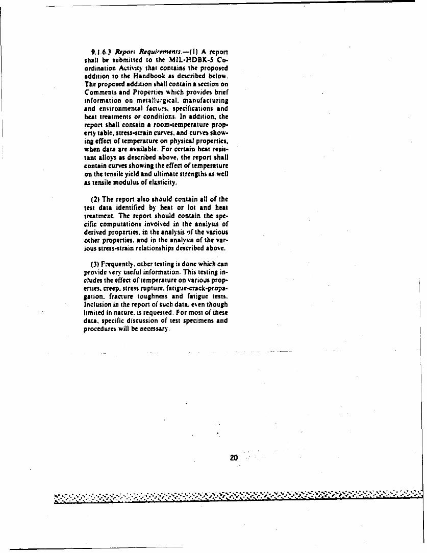
9.1.6.3 Repori Requirements.--(0) A reportshall be submitted to the MIL-HDBK-5 Co-ordination Activity that contains the proposedaddition to the Handbook as described below.The proposed addition shall contain a section onComments and Properties which provides briefinformation on metallurgical, manufacturingand environmental fact.,s, specifications andheat treatments or conditior.s. In addition, thereport shall contain a room-temperature prop-erty table, stress-strain curves, and curves show-ing effect of temperature on physical properties,when data are available. For certain heat resis-tant alloys as described above, the report shallcontain curves showing the effect of temperatureon the tensile yield and ultimate strengths as wellas tensile modulus of elasticity.
(2) The report also should centain all of thetest data identified by heat or lot and heattreatment. The report should contain the spe-ciflic computations involved in the analysis ofderiv-d properties, in the analysis )f the variousother properties. and in the analysis of the var-ious stress-strain relationships described above.
(3) Frequently. other testing is done which canprovide very useful information. This testing in-cludes the effect of temperature on various prop-erties. creep. stress rupture. fatigue-crack-propa-gation, fracture toughness and fatigue tests.Inclusion in the report of such data. even thoughlimited in nature. is requested. For most of thesedata. specific discussion of test specimens andprocedures will be necessary.
20

APPENDIX C
TEST PROGRAM FOR DETERMINATION OF DESIGNALLOWABLES FOR 17--4PH (H100) CASTING
21
-.-.- . •,•:..L•.: - . .,..- '.."-'- .''--'-'"''."--"...-''- '.- . ..'.". ..". .-. ...,",". ...-".. i•.',,,.;...: .•,"-"••-':

Item 79-2161st Meeting Agenda
Item 79-21. Design Allowables (Derived Properties) for17-4PH (HI000) Casting
Background - Currently MIL-HDBK-5 does not contain design values forcompressive yield, shear ultimate, bearing yield, and bearing ultimate strengthsfor 17-4PH castings. At the 58th MIL-HDBK-5 Coordination Meeting, it was in-dicated that these design allowable properties were needed for the HIO00 heattreat condition . Since there were no test data available in the open litera-ture, it was decided that Battelle should initiate at test program to obtainthe required data. Accordingly, letters were sent to 19 casting suppliersand 35 aerospace companies, inquiring as to whether production castings couldbe supplied for this test program.
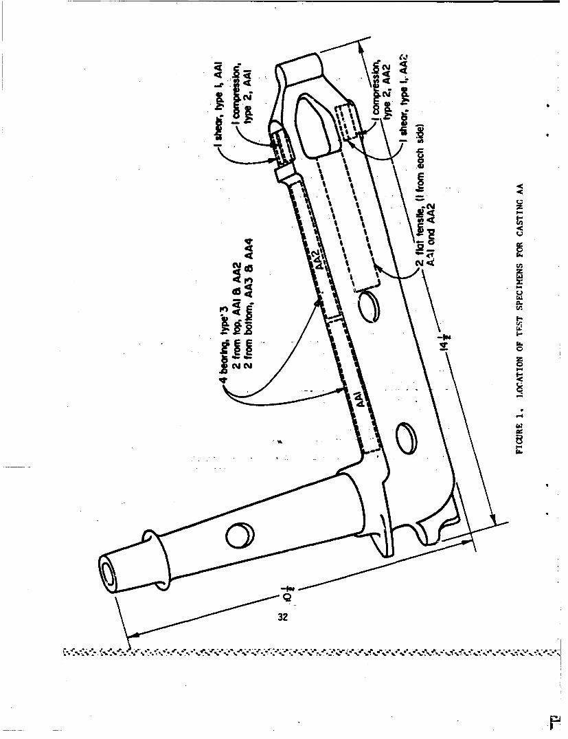
Material - As a result of this request, castings or portions ofcastings were furnished by Arwood Corp., Golden State Castings, Inc., andHemet Casting Co. In addition, parts cast by Bescast, Inc., were receivedfrom Detroit Diesel Allison and castings produced by Golden State Castings,Inc., were furnished by Hughes Helicopters. All castings were supplied at nocost to the MIL-HDBK-5 program. The castings had been produced to AMS 5343,AXS 5355 or comparable specifications. Castings which would yield the greatestnumber of test specimens were selected for testing. Fifteen castings representingfour foundries were chosen to provide test specimens. The thickness of thesecastings varied from 3/8 to 3 inches. Sketches of the selected castings orportions of castings are shown in Figures 1 through 10.
The castings received from Arwood and Detroit Diesel Allison werenot in the proper heat creat condition. Consequently, these test part- wereheat treated by a commercial heat treater to the H1000 condition in accordancewith AYS 5343 and AMS 5355 using the following procedure:
(1) Heat to 2100 + 25 F, hold at beat for not less than90 minutes, and cool to below 70F.
(2) Heat to 1900 + 25 F, hold at heat for 1 hour per inchof thickness but not less than 30 minutes and coolto below 70F.
(3) Hept to 1000 + 15 F, hold at heat for not less than
90 minutes and air cool to room temperature.
The beat treatment was performed in salt bath furnaces.
Tust Plan - Ar defined in Chapter 1, Section 1.4.1.3 of MIL-HDBK-5,derive. values are those room temperature mechanical property values that areestablished through their relationship to directly calculated (or specification)values for room temperature Ftu and Fty. The guideline for the presentation ofdata, as described in Chapter 9, Section 9.2.9.1 of MIL-HDBK-5, requires at leastten pairs of measurements, each representing a single lot of material. Basedupon the available castings, Table 1 shows the test plan to acquire the necessarydata.
22
". ..-. -•-.-o ..-................................... .- , .'.... -o . -o .- ,- --.- .......... -..... • ... . •-

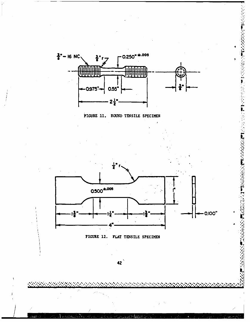
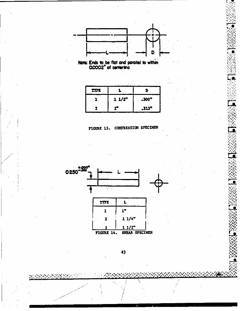
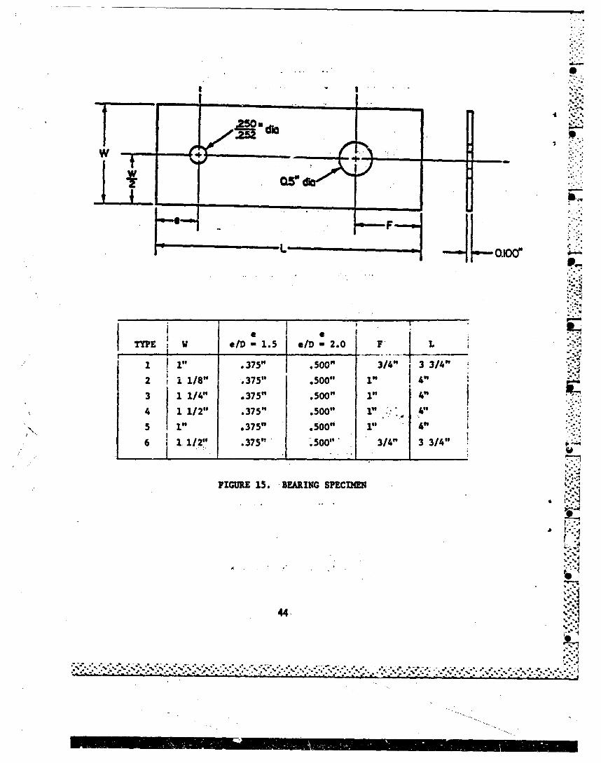
Test Specimens - Suitable castings were selected so that, in general,duplicate specimens could be obtained (Table 1). In some cases, triplicate shear"specimens were utilized. Because of the size and configuration of the castings,subsize test specimens were employed. The configurations of the test specimensare shown in Figures 11 through 15. The locations of the test specimens foreach part are indicated in Figures 1 through 10.
In order to determine internal quality, the test specimens were radio-graphed after machining. The acceptable defects in the test specimens did notexceed the requirement for Grade B of MIL-A-21180,
Testing - All testing was performed at room temperature. Prior toconducting the bearing tests, all pins, specimens, and fixtures were ultra-sonicly cleaned in acetone. After cleaning, white gloves were used in thehandling of pins, specimens and fixtures. The results of the mechanical propertytests are shown in Table 2. The tensile properties of all castings conformedto the requirements of AMS 5343.
Analysis - As previously indicated, derived values refer to thoseroom temperature mechanical property valaes that are established through theirrelationships to directly calculated (or specification) values for room tempera-ture Ftu and Fty. The procedure ia applicable to Fcy, Fsu, Fbru, and Fbry andinvolves the pairing of SUS and BUS measurements with TUS measurements for whichFtu has been established. Likewise, CYS and BYS measurements are paired withTYS measurements for which Fty has been c itablished.
Using the above relationships, reduced ratios for the various "unknown"properties were determined qsing the computational procedure described in Chapter 9,Section 9.2.9.2 of MIL-HDBK-5. The compression, shear, and bearing ratios areshown in Tables 3 and 4. Since thickness did not appear to have a significanteffect on these ratios, reduced ratios were computed using the following equation:
to. 9 55R *r - - - 0R-rn
where R - reduced ratio
r - average of n ratios
s - standard deviation of the ratios
to.95 - the 0.95 fractile of the t distribution correspondingto n-l degrees of freedom
n - number of ratios.
A computer program was used to perform the analyses. The reduced ratios areshown in Tables 3 and 4. A comparison of the reduced ratios for 17-4PH (H1000)castings with those for 17-4PH (H1025) bar, as determined ia references (1) and
(1) Ruff, P. E., "Determination of Selected NIL-HDBK-5 Design Allowable Propertiesfor Five Aerospace Materials", AFML-TR-75-58, Battelle's Columbus Laboratories,May 1975.
23

(2), as shown in Table 5. The reduced ratios for castings compare closely with
those for bar.
Using the reduced ratios in Tables 3 and 4, design values for compres-
sion yield, shear, ultimate, bearing yield, and bearing ultimate strengths werecomputed. Existing MIL-HDBK-5 Tables 2.6.9.0(i) and (J) have been revised toinclude design aflowables for these properties for the H1000 condition.. A foot-note was added to these tables to indicate that bearing values are "dry pin"values.
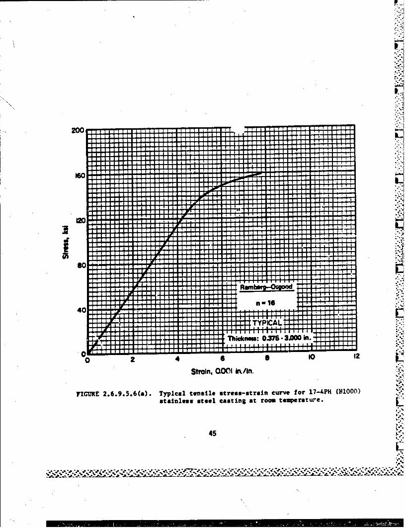
The tension and compression load-scrain curves from this investigationwere analyzed in accordance with Section 9.3.2 of HIL-HDBK-5 for the purpose of
constructing typical stress-strain curves. The Ramberg-Osgood shape parameter
for the 29 tension stress-strain curves varied from 12 to 20. The Ramberg-
Osgood parameter determined from the analysis of combined data was 16. The
Ramberg-Osgood shape parameter for the 24 compressive stress-strain curves
varied from 10 to 20. The Ramberg-Osgood parameter determined from the analysis
of combined data was 13. Typical tensile yield and compressive yield strengths
were determined from an average of all values in Table 2. The moduli of
elasticity in tension and compression were obtained from proposed Tables
2.6.9.0(i) and (J). Using these three parameters, typical tensile stress-strain,
compressive stress-strain, and compressive tangent-modulus curves were constructed.
These curves are presented in Figures 2.6.9.5.6(a) and (b).
(2) Ruff, P. E. and Smith, S. H., "Development of MIL-HDBK-5 Design AllowableProperties and Fatigue-Crack-Propagation Data for Several AerospaceMaterials", AFML-TR-77-162, Battelle's Columbus Laboratories, Octcber 1977.
24
*. ..-. ,-,. , ., ,.. ... * .. *.-,. , ., . ., -.-.. .. '.. , .. - . .. ,',., ,% .... , . ,-.%.,.,%,',..,.*.,,,, ,..."."..,,
. ./.-"* i*. -

TABLE 1. TEST PLAN FOR 17-4PH (H1000) CASTING
PartIdenti- Casting Bearing, Bearing,fication Supplier Tensile Compression Shear e/D - 1.5 e/D - 2.0
AA Arvood 2 a 2 2 2 2
AB Arvood 2 3 2
AC Arvood 2 3 2
HA Hemet 2 2 2 2 2
HB Hemet 2 2 2 2 2
HC Henet 2 2 2 2 1
HD Hemet 2 2 2
BA Bescast 2 2 2 2
BR Bescast 2 2 2 2/
GA GoldenState 2 2 3 2
GB Golden State 2 2. 3 2C Golden State 2 2 3 2
GC Golden State 2 2 3 2
GD Golden State 2 2 3 2
GE Golden State 2 2 3 2GF Golden State 2 2 32
aIndicates number of test specimens.
/2
25
S- • . • - . . . . * . . . - ' .- 1 o
;.,.-, ., -,-.- " ... " -- /' •,..',.•.':,.'''" ..... -s ,.' -' ." -:. - ' .* . " .*.S:-."*".!.'.-•...- .*.. .* '.-2-* _.•.'.*-.-
/ 7 - /, ,,7

I;
•,1es e-.-.. - dwa..... *" *-, .. q - -- "a nl nf! nntn W!
oofI
I-, -----"i+.!i *. e e
. +-. ---. I ...V4 04
I ~a ftI aJN left Pt 2
" ".. .-Lrl........ 04 -wgzoc 000.R0 2* a4* 4f
i 1 " i , , I -- s "
~ ..III fl eI nl.e . s- 4a ~ . . 1 i i .SA 444 .6 ** *aci 'a -- - - I
I I a
A I
low4 49 - . .
12 1. . . . . . .. 4 . .*
T -
as I.~~ ~ R -o -. --T i 5
1g.. 5 * w.~.v ~so. 4 af a I I
IZ- -.- :2 1 1 -1
I a 2 MAf A.. 0.4 .
to E I
26

-A_ 3. YIE,.r ZT;,Ef4G-H PATII:S Foe. 17-'PH(H10Z0) CASTING
-- -.----- /D-1.5-- P/D-2.01EN!IFICAiTZO' TYS LYx1OO loo1O BYS lo MS 10
.-TYS *TYS TYS
24F,.TAA 0.465 _THICK( ____ 57. z 104.1 149.9 176.72 7'A 6 C*625 THICK 15. c. 14.449 -.0
P F.T C0.625 THICK 156-3-a 0.R~ HA f. C*315 THI CK 15 12025 14!.?. 173.11p HS I*9 1.W3 7111;'K 157.4 101,' 11.5.7 16 i 6RTi HC C-50. T HI CK 155.4 Is 2.' 143.6 173.4
HDR iSr *15: HI~ -lo K 157.6S. 157.2 1e4DtR EA 3. 0 0- T H I ''K 1 4 10 2.5 14 6a2-
I B R 9 7o0 Tt~ICK i57.7 102@3 -.0 169.4Otc GA C*5zC THICK 153.7 104.!f 149.7 -.0PkR7 GS 0.5CO THICK......___ 15.8 o102.3 -e 17 2.8PLRT GC C*530 TWICK 155.1 101.5 148.8-.
GOT 5c 157.0 103.3 -.0 _
~RT GE c 40C IIC(1'5 1.01,o2 14.-.
PF7GF' S.375 T.H ICK - . 1564i 101.9 - 6-0 174*2
NUMBER R ±2 10 - 13AVG R 10295 V# a 02 173.5
_______ ____ U~R 1229.7 14.82.3 1_ 735.5SU'SQ :k 126018e 3 219867.2 3GI 373 .3S VE V R. 0.9847 36.3902 4..4374£tDEV RBAR S02843 1.02 3-c2 1*.4%m32
- ~ PEPCgMT, - - 0201, _ 145.9 ~1700.9 -
27
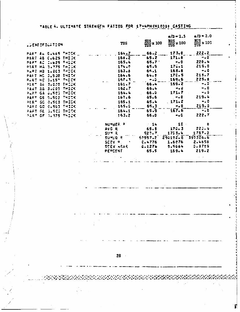
'AELE 4. ULTIMIATE STRENGTh FATIOS FOR~ 1?-4PH(MH103i ~CASTING--_ _
eID -1.5 e/D- 2.0
TSTUS TUS Tus
OAF' £A^ 0.(.5 ~MCI K . .. .161.*? 66.2 173.0 2 -22.2PART AS C*625 THIZ' 652 718-.
~r T HA 1.'?5 T":,;K 174.' 65.9 17ý61 219.0a
PA; T Hr 'eS30 T~I 41 X64.06 616.e 170.5 S.
HR MC 1 015, !',I C' 1'ST. -.l __ 169.6 __225.8
DART? GA 4.5C: TWIC'< 164.1. 66.0 01797 a.
tRý GC 1*5C3 THICK 165.1 65.. L7 17.2 -00:'Az r GO C e5(, 0 3 C< L165. 65 f,. 3 _. 2L990ZAPT G.E 3.516% Tt'CK 164.1 65.9 167.6 -. 0a'A F GF 1.7 ?'iIK'( 63.2 66.0 -.0 222.7
NU4dER. 11. IC8AVG R 6506 17003 22J.'9
s- SuQ &t -. R 6557o? 294492s 6 391326.6SCErV 0. ce 1776 1*6076 2.1.858SCEV G. 127b a0.5064 3*87!9PEocs~r 65.5 169.0 219.2
28

TABLE 5. REDUCED RATIOS FOR 17-4P- P M1000) CASTINGCWPARED TO 17-41H (O1025) BAR
Ratio 17-4P1 (10ooo) 17-4PH (H1025)Casting Bar
CYS/TYS 1.020 0.963-SUS/TUS 0.655 0.614BUS/TUS
e/D - 1.5 1.694 1.697e/D - 2.0 2.192 2.146
BTS/Tysl/D - 1.5 1.459 1.458
e/D - 2.0 1.709 1.729
kJ
aAnJ reduced rat:ios are for longiLtudinal grain -direction.--
I
S1
.o
S-.0 * *
-A,
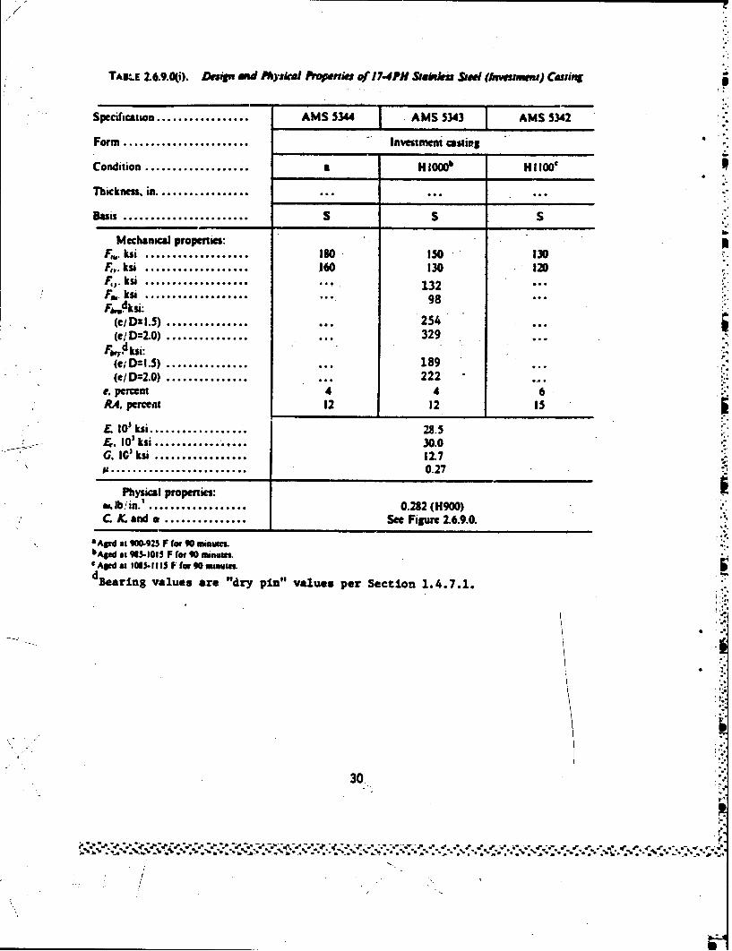
TALE 1.6.9.0(i). Desin and Physkdl Propmnk of 7.4PH Stab" Sud (Ahwumnt) Cutiffs
Specification................... AMS 5344 AMS 5343 AMS 5342
Form ... Investment cestifts
Condition .................... a HlOOb H Il100c
Tbhckness. in -................. ... ...
Basis ....................... S S S
Mechanical propenies:F,,. ksi ................... 180 150• 130F,,. ksi ................... 160 130 12DF,,, ksi ..................... 132F.w. kn ................... 98FMksi:
(e/ D:I.S) .......... ..... 254 ...
(e!D:2.0) . 329,F, ,Oksi:(e; D:I.5) .................. 189(e/D=2.0) ....... 222
e. percent 4 4 6RA. percent 12 32 Is
L I0'ksi ................ .8.5-,. I0'ksi ......... 30.0G. IC' ksi ................. 117S......................... 0.27
Physical properies:so. lb ;in.' 0.282 (H900)C. X and a ............... See Figure 2.6.9.0.
Aged at 0-g925 F for 90 min•.bAW at 98S-101S F for 90 mun•u.t Agd m 1085- 111 F far 40 mouts.dBearing values are "dry pin" values per Section 1.4.7.1.
30.
;I
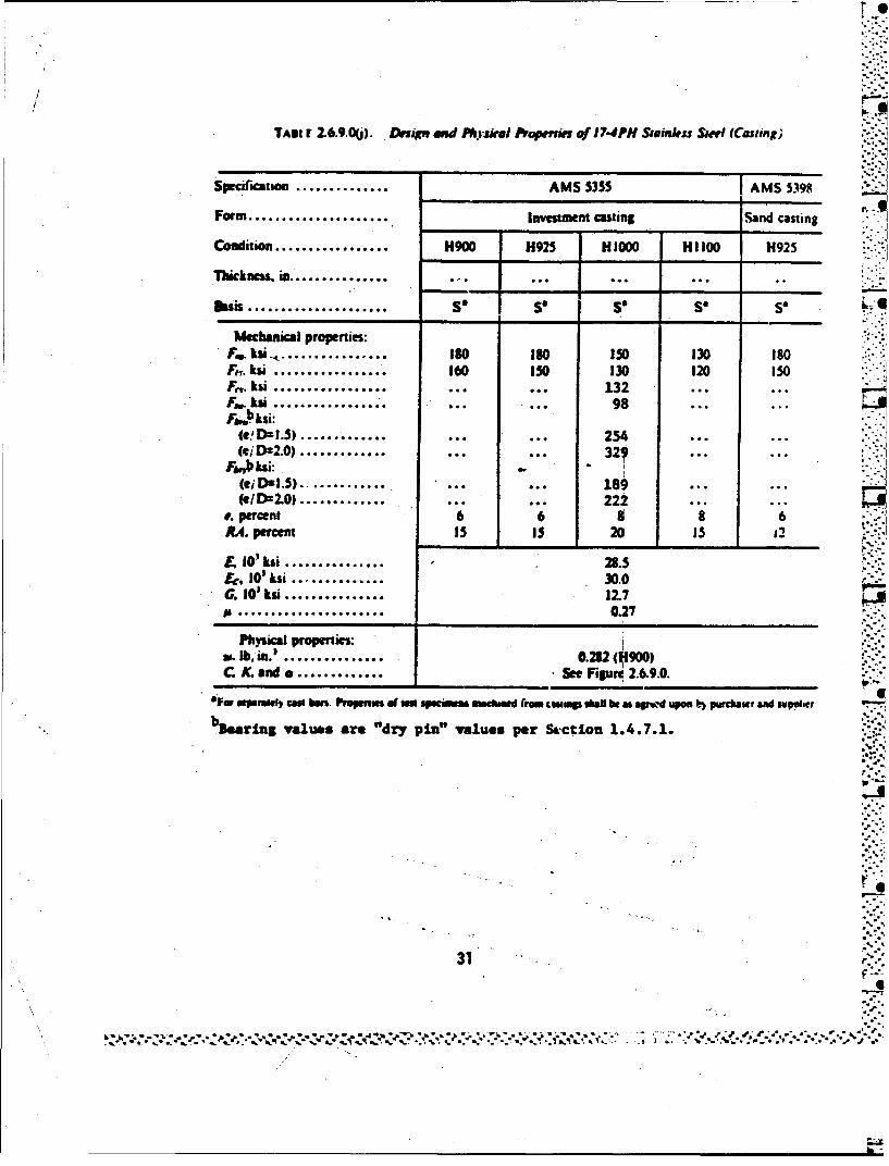
TADI F 2 .6 .9 .0(j). Drsign and PtVyskel Noplif of 17.4PH Sjainles Simi (Caling;
Specifwcatin .............. AMS 5355 AMS 5398
Form ..................... Investment casting Sand casting
C on ................. H900 H925 H 1000 H1 H192IO. .95
..i.k.. ....... "... ..
Bsis . ............. so so so so so L
Mechanical propenies:Fa. kmi. . . .. . . . . . . . . . . . . . . ISO ISO 0IS 130 ISOF,. ksi ................. 160 150 130 120 150Jrf. kbi ................• .. 98 ... ...Fr." .kt98
(e! Da1.5) ............. . ...... 254(WD=2.0) ................ ... 32.
F.bnbksi:.. ............. ... 189
(e1D2.0)..................... 222e. percent 6 6 3 8 6R,. percent 15 15 20 IS
£ I0'ksi ............... 28.5Fr. I10, li .............. 30.0G. 010 ksi ............... 12.7
..................... . 0.27
Physical properties"s,. Ib,, .. ............... M. (9)C X. and e ............. See Fieure 2.6.9.0.
SFWo uP.l*Wl cbau In Irmu Sl "Wwmu" mo/wd (toM4W twmp b9e :*a qr.'d uspom b) pm•ha•r and suppihtr
"Neauring values are "dry pin" values per Sctron 1.4.7.1.
31
31
• \ -. I
tv.
1132
Note: Specb~'es fium skMwa part kbidsfied AQ, AC2, etc
tyve 4 type.4
A53 A82 41I
3 dim yew 2
IF7.J212 2. LOCATION OF TfEST SPECIMES FOR CASTINGS AB AND AC
33
% %
4b-
06
34,

FIGRE4. OCflO 0 TST i CM~ O ATh
I *4w. 3. m35
t~ .. *.*. . * ... ~**,~* .* - t* . . .- .. . Ma l
I~~~~~s~r type, typ 2,Hl3C2rMtp
FIGURE------- 5.-LOATONOFTET-PEIMNS----ASIN -H
35, C, C

11 -
I II III
I I I2o type2,HDII II I
I II %I
I gI ,
IiI I
F U .LCTO1 rTS PM O FO CAS INGII
I3
II
._. ..... I fte:71a
* I H I
i II
I I
I I , .I I I -
I I L
116"-, I
FICURE 6. LOCATION [iF TEST SPEC]1IE':, FOR CASTINC, lid
37* . . . . . . . . .** * * . -. * * * *..o : . . . .. . . o . -. . . . . . . . . . % . . . . % %
,, ., ... .' . . , . .•. . ..... . . . . . . . . .. . -. . ...*" . -" ." .-..
S ~ . . .. . ./ *.
16coI
cc.
NY *cr~
- itr
cl1
CY :7:
in,
doq
opp
38
4 .'~2.~% ' ~ .. *16

rl>
K 80
Fh
Is 1~ 10
9 1' a a( o
IMNLi
-4- IN 59 CY gee
*6 IC a ~I
Its'
-- - - - - - - - - - - - - - -------------
39 ..
5 :-5

i Ci
N It
IS-- CI It
* It ~ tA~ It
II
CYC
9I
404
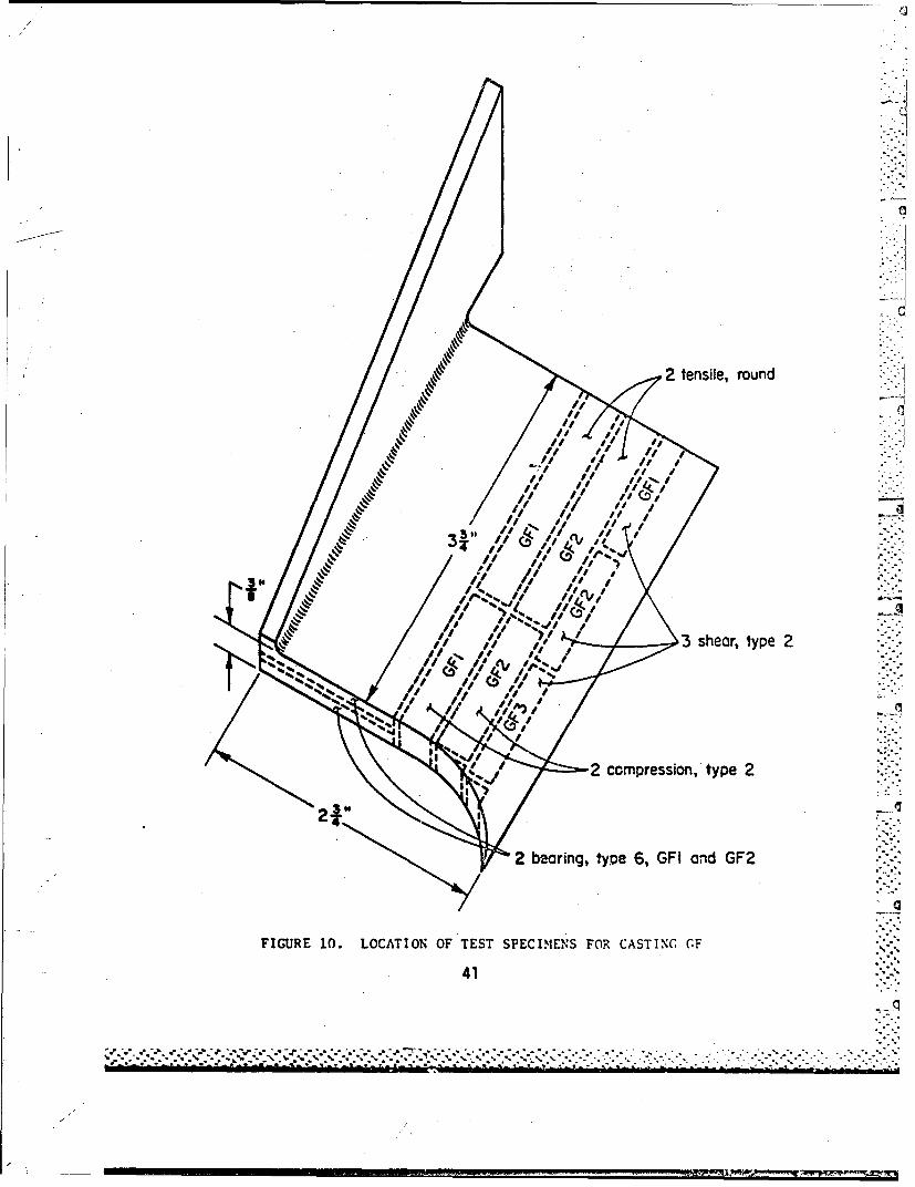
2 tensile, round
331,
3 shear, type 2
C-11
2 compression, type 2
2 bearing, type 6, GFl and GF2
FIGURE 10. LOCATION OF TEST SPECIMENS FOR CASTING CF ..
41
16N 0.250" 6.O05
w0.975".] 0.55.. "
2j
FIGURE 11. ROUND TENSILE SPECIMEN
0.5W
FIGURE 12. FLAT TENSILE SPECIMEN
42
- - -S.,
No* End t be fbt wd Wcow to -with0.02" of wntmuw
flfl L 0
* -°oO
1. 1 112" .. 00"
2 1" .313"
.FIGURE 13. C OMPRESSI ON SECII Ii i i ,"
• ' -
TY'PE L D".-.
2 1,1/4"
3 1 1/2" .FIGURE 14. SHEAR SPECIEN
43 p.
• ',..; •
S- '
- -.. S
TYP w___15_/D 20
II
I I" .375" .500" 3/4." 3 3/4"
2 1 1/8" .375" .500€ 1" 4"
3 1 1/4" .375" .500"0 1" 4.'4 1 1/2" .375" .500" 1V <4
5 1.375" .500" 4"
6 1 1/2" .375" 0500", 3/4" 3 3/4"
FIGURE 15 B /SEARING S-ECI)0 4-
44"- ""
S4 11/2" .375 .50" 1 •'" 4" :"4'
I "•
~ 4,".. . . ..... "% * " "44.... - "-~'-'-'"
00 -7
I hcnes I35.0 In.
Sitran I.0 1' /l
I I L
45 f I
_T I I I I i

4-4
120 6SdO1Srin, 001 I.n/1In.
ItI I I I I I iso If] If 20 2105
ComprssiveTanget ModLTs ? s
Iagn-ou~cre Io 174P (1100 smtils0te catn nt romte praue
*U.SQ~~~~mP~~~nI I1tn OtlIIII-5 94 51051 4I I I I
+/ P

,N
IL..c~
K 4 4* , WY.?
¼ ~ ~ ~ ~ ~ V I' A 1 V.i!
t * *S4# i>'
~~1w,