an optimization problem for quadcopter reference flight
TRANSCRIPT

Research ArticleAn Optimization Problem for Quadcopter Reference FlightTrajectory Generation
Karam Eliker 1 Guoqing Zhang1 Said Grouni2 andWeidong Zhang 13
1Department of Automation Shanghai Jiao Tong University Shanghai 200240 China2Faculty of Sciences Engineering University of Boumerdes 35000 Boumerdes Algeria3School of Computer Engineering and Science Shanghai University Shanghai 200444 China
Correspondence should be addressed to Weidong Zhang wdzhangsjtueducn
Received 22 October 2017 Accepted 29 March 2018 Published 26 July 2018
Academic Editor Howard Li
Copyright copy 2018 Karam Eliker et al This is an open access article distributed under the Creative Commons Attribution Licensewhich permits unrestricted use distribution and reproduction in any medium provided the original work is properly cited
This paper deals with the reference flight trajectory generation and planning problems for quadcopter Unmanned Aerial Vehicle(UAV) The reference flight trajectory is defined as the composition of path and motion functions Both of them are generatedby using quintic B-spline functions Based on differential flatness approach the quadcopter dynamical constraints are satisfiedinstantaneously by computing the induced aerodynamical moments and lift force The optimal reference flight trajectory withrespect to the mission requirements and imposed constraints is reached by manipulating the control pointsrsquo vectors of B-splinefunctions via a nonlinear constrained optimization method The mission requirements are defined as a set of waypoints withtheir respective scheduled flight timetable A minimum-energy cost function is developed to minimize the consumed energy andinduced efforts by reference flight trajectory For the need of the optimal overfly-times schedule the overfly times with respect tothe defined constraints and performance criteria are calculated Numerical simulation results show the feasibility and effectivenessof the proposed optimization method
1 Introduction
With a vast proliferation of Manned Aerial Vehicles (MAVs)andUnmannedAerial Vehicles (UAVs) world air transporta-tion traffic has witnessed a continuous increase causing asaturation in the airspace The formal approach adopted byresearchers to design the UAVs is to separate the avion-ics systems into three distinct and independent systemswhich are Guidance Navigation and Control (GNC) Byusing this structure UAVs could perform a variety of plan-ning missions in either military or civilian fields Howeverthere are many incidents like a collision with civil avia-tion aircraft invasion of privacy and threats to securityreported by [1] Federal Aviation Administration (FAA)These incidents are because of the lack of transportationrules and regulations supporting UAVs and the weaknesscurrent structure UAVs Therefore the need to integratethe UAVs in National Airspace System (NAS) is highlyrecommended
To achieve this challenge an adequate flight trajectoryplanner that could be embedded on quadcopter UAV shouldbe developed The flight trajectory planner could reduceuncertainty and increase predictability for Air Traffic Man-agement (ATM) Planning missions in terms of waypointswith overfly times at which the UAV is scheduled to overflycould be a challenging problem for trajectory generationMost of the previous works have focused on 3D trajectoryplanning problem and consider only waypoints without anyoverfly-times constraints By contrast this paper proposesa new optimization method to generate the reference flighttrajectory that could fulfill some related requirements ofNASTheproposed flight trajectory planning should generatea trajectory that complies with the considered quadcopterdynamical constraints and meets the assigned missions Theassigned missions contain a set of waypoints with theirrespective scheduled flight timetable For the necessity ofoptimal overfly-times schedule the overfly times can becalculated in optimal way while considering the assigned
HindawiJournal of Advanced TransportationVolume 2018 Article ID 6574183 15 pageshttpsdoiorg10115520186574183
2 Journal of Advanced Transportation
constraints and performance criteria By generating suchreference flight trajectory different tasks such as deliveringand reconnaissance missions at acceptable overfly timescould be performed Moreover the traffic managements forUAV could be enhanced by managing the scheduled flighttimetable of waypoints
Several papers of 3D trajectory planning problems whileconsidering waypoints as physical points in the workspacehave been done On one hand the authors in [2ndash7] pro-posed an optimization approach to solve Time OptimalMotion Planning (TOMP) between two configuration pointsby using a Nonlinear Programming (NLP) method Onthe other hand the authors in [8ndash10] have proposed analgorithm based on Pontryaginrsquos minimum principle tosolve TOMP between two states In [11] the authors pre-sented an approach that could link separate trajectoriesto form smooth analytically defined paths while satisfy-ing a set of waypoint constraints Moreover in [12ndash14]a minimum snap cost function was designed to generatesmooth trajectory while satisfying a sequence of consecutivewaypoints In [15] a quasi-optimal trajectory generationwas developed to satisfy constraints concerning waypointsand their overfly times while minimizing the trajectorylength
Moreover some papers have dealt with the minimum-energy problem In [16] a quasi-optimal trajectory plannerwas proposed to generate trajectory between two pointsThe objective function was defined as a fuel consumptionproblem by considering the cost function as an averagevelocity The authors in [17] supposed that the consumedenergy was proportional to the rotors velocities In [18] theauthors designed a trajectory planning function for a small-scale helicopter in autorotation which could minimize thebattery power consumption and avoid bang-bang type solu-tions Nonlinear Programming problemwas used to computethe optimal polynomial coefficients of the trajectory whileminimizing the cost function written as the rate of all forcesand moments applied on helicopter In [19] a minimum-energy trajectory generation approach was proposed bydefining the cost function as a function of the voltageand current across the four rotors The similarity amongthese papers was the reference trajectory planning problemsdefined as longitudinal lateral and altitude displacementsas NLP problem between two configuration points while thedifferencewas related to the parameterization of the referencetrajectory
The objective of this paper is the reference trajectorygeneration and planning problems for quadrotor UAV Thereference flight trajectory is defined as a composition ofpath andmonotonically increasingmotion functions Both ofthemare generated by using quintic B-spline functions Basedon differential flatness approach the quadcopter dynamicalconstraints are checked instantaneously by computing theinduced aerodynamical roll and pitch headingmoments andlift force respectivelyThe optimal reference trajectory whichconsists of longitudinal lateral and altitude displacementsin addition to yaw angle is reached by manipulating thecontrol pointsrsquo vectors of B-spline functions via a nonlinearconstrained optimization method while taking into account
the mission requirements and defined constraints The mis-sion requirements are defined as a sequence ofwaypointswiththeir respective scheduled flight timetable and eachwaypointcould represent a particular posture A minimum-energycost function is designed to enhance the performance cri-teria regarding trajectory length induced efforts consumedenergy and trajectory smoothness For the optimal overfly-times schedule requirement the overfly times are calculatedby the proposed optimization method with regard to theinterested constraints and performance criteria Several con-figurations are studied and numerical simulation results showthe feasibility and effectiveness of the proposed optimizationmethod
2 Quadcopter Flight Dynamics
The quadcopter UAV is a vertical take-off and landing(VTOL) aircraft Its main characteristics are the ability ofhovering vertical take-off and landing in any terrain Thedisplacement and rotation motions are achieved by adjustingthe angular speed of each rotor To design the reference flighttrajectory a simplified quadcopter flight dynamics are usedto reduce the computation burden and to facilitate the opti-mization problem implementation By considering that thequadcopter UAV performs angular motions of low amplitudeand omitting the drag force aerodynamical frictions andgyroscopic effects moments the simplified dynamic modelof quadcopter UAV in contrast to full quadcopter dynamicspresented in [21 22] is given by
120601 = 1119868119909119880120601 (1a)120579 = 1119868119910119880120579 (1b)
= 1119868119911119880120595 (1c)
= 119880119911119898 (cos120601 sin 120579 cos120595 + sin120601 sin120595) (1d)
119910 = 119880119911119898 (cos120601 sin 120579 sin120595 minus sin120601 cos120595) (1e)
= minus119892 + 119880119911119898 (cos120601 cos 120579) (1f)
where 119909 119910 119911 are longitudinal lateral and altitude displace-ments and120601 120579 120595 are roll pitch and yaw angles in the Earth-fixed frame respectively 119892 is the gravity acceleration and 119898is the mass of quadcopter UAV 119868119909 119868119910 119868119911 are roll pitch andyaw inertia moments respectively The lift force 119880119911 and theaerodynamical roll 119880120601 pitch 119880120579 and heading 119880120595 momentsdeveloped by the quadcopter UAV are expressed with respectto the rotors velocities
Journal of Advanced Transportation 3
(119880119911119880120601119880120579119880120595)= ( 119862119871 119862119871 119862119871 1198621198710 119889119862119871 0 minus119889119862119871minus119889119862119871 0 119889119862119871 0minus119862119863 119862119863 minus119862119863 119862119863 )(12059621120596221205962312059624)
(2)
where 119862119871 and 119862119863 are lift and drag force coefficients respec-tively 119889 is the distance between the centermass of quadcopterand the axis of the propeller 120596119894 is the rotor 119894 velocity 119894 =1 2 3 4 From (1d) (1e) and (1f) roll (120601) and pitch (120579)angles are expressed as follows
120601 = arcsin( sin120595 minus 119910 cos120595radic2 + 1199102 + ( + 119892)2) (3a)
120579 = arctan( cos120595 + 119910 sin120595 + 119892 ) (3b)
Using (1a)ndash(1f) the aerodynamical roll pitch and head-ing moments and lift force which are induced by thereference flight trajectory are expressed as follows119880120601 = 119868119909 120601 (4a)119880120579 = 119868119910 120579 (4b)119880120595 = 119868119911 (4c)119880119911 = 119898radic2 + 1199102 + ( + 119892)2 (4d)
Based on (3a) and (3b) it can be concluded that theanalytical expressions of 120601 120579 120601 and 120579 are functions ofthe first second third and fourth derivatives of the vectorcomponents (119909 119910 119911 120595)3 Optimization Problem Formulation
The optimization problem is concerned with the referenceflight trajectory that satisfies waypoints constraints at specificschedule flight timetable Since the quadcopter UAV canperform six Degrees of Freedom (DOF) the reference flighttrajectory could contain six components
I (119905) = (119909119889 (119905) 119910119889 (119905) 119911119889 (119905) 120601119889 (119905) 120579119889 (119905) 120595119889 (119905)) (5)
However the quadcopter UAV is an underactuated sys-tem Only longitudinal lateral and altitude displacements(119909 119910 119911) and yaw angle (120595) can be directly controlled Roll (120601)and pitch (120579) angles are systemically computed with respectto quadcopter dynamics Differential flatness approach hasshown interesting performance regarding the trajectory plan-ning problem as demonstrated in [4 5 8 12ndash14 16ndash18] Using
the differential flatness method the state space variables andcontrol inputs can be defined in terms of flat output vectorFurthermore the computation load on optimization couldbe reduced considerably Equations (1a)ndash(1f) are differentiallyflat if there exists a flat output vector 120578 isin R119898 in the followingform [23]
120578 = 120577 (x u u u u(119903)) (6)
such that
x = 120572 (120578 (119902)) (7a)
u = 120573 (120578 (119902)) (7b)
where x and u are state space and control input vectorsrespectively From (1a)ndash(1f) (3a)-(3b) and (4a)ndash(4d) it canbe concluded that the vector (119909 119910 119911 120595) represents the flatoutput 120578(119905) vector Therefore the optimization problem canbe treated from the flat output 120578(119905) vector and expressed asNLP problem in the following form
min 119869 (120578 (119905)) for 119905 isin [0 119879] (8a)
such that ℎ (120578 (119905)) = 0 (8b)119892 (120578 (119905)) ⩽ 0 (8c)
where (8b) and (8c) denote a set of equality and inequalityconstraints respectively 119869(120578(119905)) is the objective function31 Mission Requirements and Constraints The consideredconstraints are classified as follows
(a) Mission Constraints The mission constraints are definedas a set of conditions as follows
(i) The quadcopter UAV posture
I (0) = Iinit (9a)
I (119905119894) = I119894 119894 = 1 119899waypoint (9b)0 lt 1199051 lt 1199052 lt sdot sdot sdot lt 119905119899waypoint lt 119879 lt 119879aut (9c)
I (119879) = Ifin (9d)
where 119879aut and 119879 are autonomy flight and final timesrespectively 119899waypoint is the number of waypoints
(ii) The quadcopter UAV scheduled flight timetable119905lowast119894 minus 120575119905 ⩽ 119905119894 ⩽ 119905lowast119894 + 120575119905 (10)
where 119905lowast119894 is the predefined overfly time and 120575119905 is anallowed range of overfly time
(iii) The quadcopter UAV velocity
I (0) = 997888rarr0 (11a)
I (119879) = 997888rarr0 (11b)
4 Journal of Advanced Transportation
(b) Workspace and Flight Envelope Constraints
(i) The workspace limits120601min ⩽ 120601119889 (119905) ⩽ 120601max (12a)120579min ⩽ 120579119889 (119905) ⩽ 120579max (12b)120595min ⩽ 120595119889 (119905) ⩽ 120595max (12c)119909min ⩽ 119909119889 (119905) ⩽ 119909max (12d)119910min ⩽ 119910119889 (119905) ⩽ 119910max (12e)119911min ⩽ 119911119889 (119905) ⩽ 119911max (12f)
(ii) The flight envelope limits the flight envelope is a setof flight conditions defined by the quadcopter heightand airspeed119911min ⩽ 119911119889 (119905) ⩽ 119911max (13a)min ⩽ 119889 (119905) ⩽ max (13b)0 ⩽ 119881119886 ⩽ 119881MO (13c)
where 119881MO is the maximum operating speed
(c) Induced Efforts Constraints From (2) the induced effortscan be expressed as follows0 ⩽ 119880119911 ⩽ 41198621198711205962max (14a)minus1198891198621198711205962max ⩽ 119880120601 ⩽ 1198891198621198711205962max (14b)minus1198891198621198711205962max ⩽ 119880120579 ⩽ 1198891198621198711205962max (14c)minus21198621198631205962max ⩽ 119880120595 ⩽ 21198621198631205962max (14d)
Since the quadcopter rotors are identical 120596max denotesthe maximum rotor velocity
32 Reference Flight Trajectory Parameterization The refer-ence trajectory can be defined as a composition [3 6 15 24]of path and motion functions Based on this definition thevelocity acceleration jerk and snap profiles of referenceflight trajectory could be adjusted to make them compliantwith the assigned constraints The reference flight trajectoryI(119905) = (119909119889(119905) 119910119889(119905) 119911119889(119905) 120595119889(119905)) is written as follows
I (119905) = 119875 (120582) ∘ 120582 (119905) = 119875 (120582 (119905)) (15a)
I (119905) = (119905) 119889119875119889120582 (120582 (119905)) (15b)
I (119905) = (119905) 119889119875119889120582 (120582 (119905)) + 2 (119905) 11988921198751198891205822 (120582 (119905)) (15c)
I (119905) = 120582 (119905) 119889119875119889120582 (120582 (119905)) + 3 (119905) (119905) 11988921198751198891205822 (120582 (119905))+ 3 (119905) 11988931198751198891205823 (120582 (119905)) (15d)
I(4) (119905) = 120582(4) (119905) 119889119875119889120582 (120582 (119905))+ 4 (119905) 120582 (119905) 11988921198751198891205822 (120582 (119905))+ 32 (119905) 11988921198751198891205822 (120582 (119905))+ 62 (119905) (119905) 11988931198751198891205823 (120582 (119905))+ 4 (119905) 11988941198751198891205824 (120582 (119905))
(15e)
where the path 119875(120582) is a set of time-independent configura-tions followed by the quadcopter UAV to fly from an initialconfiguration 119875init to a final one 119875fin The motion 120582(119905) is apositive scalar function that defines the way in which thepath is achieved with respect to the time 120582 isin [0 1] Inorder to construct the path 119875(120582) and motion 120582(119905) functionsa parametric function has to be selected For this purposeB-spline function is used for its advantage to support themanipulation of the reference trajectory as functions ofcontrol points and knot vectors Basically B-spline functionis demonstrated as follows [24]119878 (119906) = 119873sum
119894=1
119888119894119861119901119894 (119906) (16)
with 1199060 le sdot sdot sdot le 119906119895minus1 le 119906119895 le 119906119895+1 le sdot sdot sdot le 119906119899knot (17)
where 119888119894 is a control point and 119873 is a control points number119906 is a knot vector and 119899knot is the number of knots 119861119901119894 is abasis function of degree 119901 For this purpose the knot vectorsare selected as uniform sequences To construct the path andmotion functions the following conditions are defined
(a) Path Function 119875(120582)(i) Posture condition it satisfies the condition indicated
in (9a)ndash(9d)119875 (120582 = 0) = 119875init (18a)119875 (120582119894) = 119875119894 119894 = 1 119899waypoint (18b)119875 (120582 = 1) = 119875fin (18c)
(ii) Velocity condition it ensures the condition of(11a) and (11b) (120582 = 0) = 997888rarr0 (19a) (120582 = 1) = 997888rarr0 (19b)
(c) Motion Function 120582(119905)(i) The first derivative of 120582(119905)119889120582119889119905 ⩾ 0 forall119905 isin [0 119879] (20)
Journal of Advanced Transportation 5
Motion control points(t)
I5
I4
I3
I2
I1
0 T
Time (s)
0
02
04
06
08
1M
otio
n fu
nctio
n(t)
(a)
Path control pointsP()
10
minus30
minus20
minus10
0
10
20
Path
func
tion
P(
)
(b)
Figure 1 An illustration example for (a) motion 120582(119905) and (b) path 119875(120582) functions respectively(ii) The motion must satisfy the following conditions120582 (0) = 0 (21a) (0) = 0 (21b) (0) = 0 (21c)
120582 (0) = 0 (21d)120582 (119879) = 1 (21e) (119879) = 0 (21f) (119879) = 0 (21g)120582 (119879) = 0 (21h)
(iii) The overfly-time conditions120582 (119905119894) = 120582119894 119894 = 1 119899waypoint (22)
From (3a)-(3b) and (15a)ndash(15e) the continuity of thesecond-order derivatives of the desired roll 120601119889(119905) and pitch120579119889(119905) angles depends on the continuity of the fourth derivativeof the path and motion functions Therefore the parametricfunction of 119875(120582) is modeled as a quintic B-spline functionusing (119873119901 + 2) control points number where 119873119901 ⩾ 5 The(119873119901) control points number represents a set of path controlpoints that will be manipulated by the proposed optimizationmethod The (2) control points number represents the fixedcontrol points that satisfy the condition expressed in (18a)and (18c) The parametric function of 120582(119905) is modeled asa quintic B-spline function using (119873119898 + 8) control pointsnumber The (119873119898) control points number is a set of motioncontrol points and the (8) control points number is a setof fixed control points that meet conditions defined by(11a)-(11b) and (21a)ndash(21h) In addition the motion control
pointsrsquo vector is uniformly distributed along the time scaleguarantying that each motion control point belongs to anincreasing bounded interval to satisfy the condition of (20)Figure 1 illustrates an example for path and monotonicallyincreasing motion functions respectively
4 Performance Criterion
For rotor-craft systems the electrical power is convertedto mechanical power in the form of thrust The developedmechanical power could be described as the product ofthe torque 120591119894 and angular velocity 120596119894 Therefore the powergenerated from each rotor 119894 could be computed as follows119875119894 = 120591119894120596119894 = (1198621198631205962119894 ) 120596119894 (23)
By using the first term 1198621198631205962119894 in (23) the proposed costfunction is expressed as a function of rotor velocities and yawdynamics
119869 = int1198790
[[( 4sum119894=1
1198621198631205962119894 )2 + 2]]119889119905 (24a)
= int1198790[1198622119863 (12059621 + 12059622 + 12059623 + 12059624)2 + 2] 119889119905 (24b)
= int1198790[120573 (2 + 1199102 + ( + 119892)2) + 2] 119889119905 (24c)
with 120573 = (119862119863 119898119862119871)2 (25)
where the term 2 is used to minimize the induced aerody-namical headingmoment and the second term120573(2+ 1199102+(+
6 Journal of Advanced Transportation
Step 1
Step 2
Step 3
Definition of constraints
Suggestion of initial solution
Control points vectors
Path control points Motion control points
Uniform path knot sequences vector
Uniform motion knot sequences vector
Bounded interval of
each motion control point
Fix maximum tolerance and iteration
Initialization
Mission requirements
Workspace and flight envelope limits
Induced efforts constraints
Step 1
Step 2
Proposed optimization for reference trajectory
generation
Generating optimal reference trajectory using
B-spline functions
Optimization
Current solution
Generating reference trajectory using
B-spline functions
Induced efforts Computation
Cost function
Nonlinearconstraints
Equalityconstraints
Inequality constraints
Desired roll and pitch angles computation
Final time T
control pointsvectors
Minimize cost
function
Reach maximum tolerance or iteration
Update the current solution
Optimal Solution
Optimal overfly-times Optimal final Optimal control points vectors
No
Yes
time TIJNCGF
ti_IJNCGFi = 1 nQSJICHNM
(Nm + 8) vector(Np + 2) vector
i = 1 nQSJICHNM
Overfly-times ti
Figure 2 Proposed optimization method procedure
119892)2) is introduced in the proposed cost function to minimizethe induced efforts and consumed energy This yields119869 = int1
0[120573((119889211991111198891205822 )2 + (119889211991121198891205822 )2 + (119889211991131198891205822 + 119892)2)
+ (119889211991141198891205822 )2]119889120582 (26)
The synoptic procedure of optimizationmethod is shownin Figure 2 For fixed scheduled flight timetable problem onlythe positions of the control pointsrsquo vectors are manipulatedThe final solution will be the optimal control pointsrsquo vectorsFor this problem the overfly-time constraints defined shouldbe selected properly For the requirements of the optimaloverfly-times schedule the overfly times are calculated bythe proposed optimization problem with respect to theconstraints of interest and performance criteria
5 Numerical Simulations
51 Flight Trajectory 1 Let us consider the following con-figuration in Table 1 All simulations are done using 119873119898 =
Table 1 Waypoints configuration with their scheduled flight time-table
Waypoint 119905 (s) 119909 (m) 119910 (m) 119911 (m) 120595 (rad)Initial 0 5 minus5 0 01 10 10 0 20 minus017452 25 0 15708 20 034913 43 minus10 0 20 052364 68 0 minus15708 20 017455 80 10 0 20 0Final 95 5 5 0 012 and 119873119901 = 14 The constraints are listed in Table 3The real parameters identified in [20] are used to test theproposed optimization method (see Table 2) A numericalsolver in Matlab [25] via ldquofminconrdquo based upon SequentialQuadratic Programming (SQP) is used to solve the optimiza-tion method To demonstrate the effectiveness of proposedcost function in (26) different cost functions defined in[15 17] are used Figure 3 displays the 2D and 3D referenceflight trajectory with respect to the requirements of Table 1
Journal of Advanced Transportation 7
0minus20
20
10
10Longitudinal x (m)
0
20
0
Alti
tude
z (m
)
Lateral y (m)minus10
30
20 minus20
40
Minimum-energyMinimum-length [15]Minimum-energy [17]
Initial configurationWaypointsFinal configuration
t3 = 43 st2 = 25 s
t1 = 10 st4 = 68 s t5 = 80 s
tCHCN = 0 sT = 90 s
(a)
Longitudinal x (m)
Late
ral y
(m)
minus20 minus10 0 10 20minus20
minus10
0
10
20
t3 = 43 s
t2 = 25 s
t1 = 10 s
t4 = 68 s
t5 = 80 s
tCHCN = 0 s
T = 90 s
Minimum-energyMinimum-length [15]Minimum-energy [17]
Initial configurationWaypointsFinal configuration
(b)
Figure 3 Optimal 3D and 2D reference flight trajectory
Table 2 Quadcopter UAV parameters [20]
Parameter Value119868119909 00059 kgsdotm2119868119910 00059 kgsdotm2119868119911 00107 kgsdotm2119898 0694 kg119862119863 118 times 10minus7Nsdotmrads119862119871 38162 times 10minus6 Nrads119889 018mTable 3 Considered constraints
Constrainttypes Constraints Constraint ranges
Workspace
Longitudinaldisplacement (m) minus30 ⩽ 119909 ⩽ 30
Lateral displacement (m) minus40 ⩽ 119910 ⩽ 40Altitude (m) 0 ⩽ 119911 ⩽ 120
Roll angle (rad) minus05236 ⩽ 120601 ⩽ 05236Pitch angle (rad) minus06109 ⩽ 120579 ⩽ 06109Yaw angle (rad) minus07854 ⩽ 120595 ⩽ 07854
Flight envelopeHeight (m) 0 ⩽ 119911 ⩽ 120
Yaw rate (rads) minus17454 ⩽ ⩽ 17454Airspeed (ms) 0 ⩽ 119881119886 ⩽ 8
Actuators Maximum rotorvelocity (rads) 0 ⩽ 120596max ⩽ 1047
It could be noted that the proposed algorithm can dealwith different cost functions Moreover the smoothness ofthe generated reference flight trajectory depends on theconsidered cost functions Figure 4 shows the generated
Table 4 Comparison results of trajectory length and fitness value
Cost function type Trajectory length (m) Fitness value1 Minimum-energy 12916 11174 times 1032 Minimum-length [15] 11705 13609 times 1043 Minimum-energy [17] 13625 12241 times 104longitudinal lateral and altitude displacements in additionto yaw angle Figures 6 and 7 illustrate the induced effortsdeveloped by each cost function It could be seen from theproposed cost function in (26) that the mean values of theinduced efforts are considerably less than those related tothe cost functions in [15 17] Figure 5 displays the resultsgiven by each cost function in regards of trajectory lengthand consumed energy The fitness value developed by theproposed cost function which reflects consumed energyis less important than other cost functions The proposedcost function shows an interesting performance in termsof trajectory length induced efforts consumed energy andsmoothness as demonstrated in Tables 4 and 5
52 Flight Trajectory 2 Let us consider the configuration inTable 6 Simulations are done by considering three scenariosIn the first one the waypoints overfly times are fixed In thesecond one the waypoints overfly times are freely computedby the proposed optimization method However in the lastcase an allowed range of overfly time (120575119905 = 5 s) is used
Figure 8 displays the 3D and 2D generated referenceflight trajectory for the three scenarios Even if the imposedwaypoints overfly times defined in Table 6 are fixed withoutany prior knowledge on optimality aspect the proposed opti-mizationmethodwill show its ability to generate the referencetrajectory of desired configuration despite its weakness in
8 Journal of Advanced Transportation
0
0 25 43 68 80 9510Time (s)
minus20
minus10
10
20di
spla
cmen
txd
(m)
Minimum-energyMinimum-length [15]Minimum-energy [17]
Long
itudi
nal
(a)
Late
ral
minus20
minus10
0
10
20
disp
lacm
entyd
(m)
Minimum-energyMinimum-length [15]Minimum-energy [17]
0 25 43 68 80 9510Time (s)
(b)
Minimum-energyMinimum-length [15]Minimum-energy [17]
0
10
20
30
40
disp
lacm
entz d
(m)
0 25 43 68 80 9510Time (s)
Alti
tude
(c)
Yaw
minus1
0
1
angl
ed
(rad
)
Minimum-energyMinimum-length [15]Minimum-energy [17]
0 25 43 68 80 9510Time (s)
(d)
Figure 4 Desired (a) longitudinal (b) lateral and (c) altitude displacements and (d) heading angle respectively
2 31Cost function
0
50
100
150
Traj
ecto
ry le
ngth
(m)
(a)
0
5000
10000
15000
Fitn
ess v
alue
2 31Cost function(b)
Figure 5 Performance criterion (a) trajectory length and (b) fitness value respectively
terms of induced efforts length trajectory and consumedenergy as demonstrated in Figures 9 and 11 Table 8 showsthe optimal overfly-times schedule computed in the secondand third scenarios
Figures 10 and 11 illustrate the induced lift force aerody-namical moments and their mean values computations withrespect to each scenario Based on the proposed optimizationproblem the overfly times are computed optimally andconsequently the induced efforts trajectory length andconsumed energy could be considerably reduced Tables 7and 9 show this aspect
53 Flight Trajectory 3 Let us consider the same configura-tion in Table 6 In this study different 120575119905 is used and 119879aut =
20min is fixed Figure 12 displays the 3D and 2D generatedreference flight trajectory and Table 10 shows the optimaloverfly-times schedule computed for each selected 120575119905 Figures13 14 and 15 display the trajectory length consumed energyand induced efforts developed by selecting 120575119905 Tables 11 and12 display the performance criteria assessment It can beseen that while 120575119905 increased the performance criteria showedenhancing results
6 Conclusion
An optimizationmethod for reference flight trajectory gener-ation has been proposed which allows the generation of feasi-ble and realistic flight plan for quadcopter UAV and manages
Journal of Advanced Transportation 9Li
ft fo
rce
Minimum-energyMinimum-length [15]Minimum-energy [17]
6
8
Uz
(N)
20 40 60 80 950Time (s)
(a)
Roll
mom
ent
times10minus4
minus3minus2minus1
012
U
(Nmiddotm
)
Minimum-energyMinimum-length [15]Minimum-energy [17]
20 40 60 80 950Time (s)
(b)
Pitc
h m
omen
t
times10minus4
minus2
minus1
0
1
2
U
(Nmiddotm
)
Minimum-energyMinimum-length [15]Minimum-energy [17]
20 40 60 80 950Time (s)
(c)
Hea
ding
mom
ent
times10minus4
minus5
minus202
5
U
(Nmiddotm
)
Minimum-energyMinimum-length [15]Minimum-energy [17]
20 40 60 80 950Time (s)
(d)
Figure 6 Induced efforts (a) lift force and aerodynamical (b) roll and (c) pitch and (d) heading moments respectively
Lift
forc
e
0
2
4
6
8
Uz
(N)
2 31Cost function(a)
Roll
mom
ent
times10minus5
2 31Cost function
0
1
2
3
U
(Nmiddotm
)
(b)
Pitc
h m
omen
t
times10minus5
0
1
2
3
U
(Nmiddotm
)
2 31Cost function(c)
Hea
ding
mom
ent
times10minus4
0
05
1
15
U
(Nmiddotm
)
2 31Cost function(d)
Figure 7 Mean values of (a) lift force and aerodynamical (b) roll and (c) pitch and (d) heading moments respectively
10 Journal of Advanced Transportation
Table 5 Comparison results of induced efforts
Cost function type Lift force Roll moment Pitch moment Heading moment(N) (Nsdotm) (Nsdotm) (Nsdotm)
1 Minimum-energy 68092 50493 times 10minus6 74343 times 10minus6 23455 times 10minus52 Minimum-length [15] 6811 24896 times 10minus5 19401 times 10minus5 69616 times 10minus53 Minimum-energy [17] 68089 41299 times 10minus6 65995 times 10minus6 10246 times 10minus4
0minus30 50
minus15
40
Lateral y (m)0 0
Alti
tude
z (m
)
15
80
30 minus50
120
Longitudinal x (m)
Scenario 1Scenario 2Scenario 3
(a)
minus30 minus15 0 15 30Longitudinal x (m)
minus40
minus20
0
20
40
Late
ral y
(m)
Scenario 1Scenario 2Scenario 3
(b)
Figure 8 Optimal 3D and 2D reference flight trajectory
2 31Scenario
0
100
200
300
Traj
ecto
ry le
ngth
(m)
(a)
2 31Scenario
0
05
1
15
2
Fitn
ess v
alue
times104
(b)
Figure 9 Performance criterion (a) trajectory length and (b) fitness value respectively
adequately the scheduled flight timetable of waypoints In thispaper the flight trajectory generation problem was treatedas NLP problem and solved via a nonlinear constrainedoptimization technique The reference flight trajectory wasdefined as a composition of path and motion functions Bothof themwere generated by using B-spline functions Based ondifferential flatness approach the quadcopterUAVdynamicalconstraints were checked instantaneously by computing theinduced aerodynamical roll pitch and headingmoments andlift force respectively The optimal reference trajectory was
reached by manipulating the control pointsrsquo vectors of B-spline functions while taking into account the quadcoptermission requirements dynamical constraints flight envelopeandworkspace limitsThemission requirementswere definedas a series of waypoints with their respective scheduled flighttimetable A minimum-energy cost function has been pro-posed to minimize the consumed energy and induced effortsalong the path For requirement of optimal overfly-timesschedule the overfly times were computed in an optimal wayregarding the defined constraints and performance criteria
Journal of Advanced Transportation 11Li
ft fo
rce
Scenario 1Scenario 2Scenario 3
50 100 1400Time (s)
6
65
7
75
8
Uz
(N)
(a)
Roll
mom
ent
times10minus4
minus2
0
2
U
(Nmiddotm
)
Scenario 1Scenario 2Scenario 3
50 100 1400Time (s)
(b)
Scenario 1Scenario 2Scenario 3
Pitc
h m
omen
t
times10minus4
minus2
0
2
U
(Nmiddotm
)
50 100 1400Time (s)
(c)
Hea
ding
mom
ent
times10minus4
minus1
0
1
2
U
(Nmiddotm
)
Scenario 1Scenario 2Scenario 3
50 100 1400Time (s)
(d)
Figure 10 Induced efforts (a) lift force and aerodynamical (b) roll and (c) pitch and (d) heading moments respectively
Lift
forc
e
2 31Cost function
0
2
4
6
8
Uz
(N)
(a)
Roll
mom
ent
2 31Cost function
times10minus5
0
1
2
U
(Nmiddotm
)
(b)
Pitc
h m
omen
t
2 31Cost function
times10minus5
0
05
1
15
U
(Nmiddotm
)
(c)
Hea
ding
mom
ent
2 31Cost function
times10minus5
0
1
2
3
4
U
(Nmiddotm
)
(d)
Figure 11 Mean values of (a) lift force and aerodynamical (b) roll and (c) pitch and (d) heading moments respectively
12 Journal of Advanced Transportation
0minus20 30
20minus100Longitudinal x (m)
0
40
Lateral y (m)minus2010
Alti
tude
z (m
)
20 minus40
80
100
t = 10
t = 4t = 25t = 06
(a)
minus30 minus15 0 15 30Longitudinal x (m)
minus40
minus30
minus20
minus10
0
10
20
30
40
Late
ral y
(m)
t = 10
t = 4t = 25t = 06
(b)
Figure 12 Optimal 3D and 2D reference flight trajectory
0
100
200
250
Traj
ecto
ry le
ngth
(m)
25 4 1006t (s)
(a)
0
2000
4000
6000
8000
10000
Fitn
ess v
alue
25 4 1006t (s)
(b)
Figure 13 Performance criterion (a) trajectory length and (b) fitness value respectively
Table 6 Waypoints configuration with their scheduled flight time-table
Waypoint 119905 (s) 119909 (m) 119910 (m) 119911 (m) 120595 (rad)Initial 0 5 minus5 0 01 10 5 0 20 minus017452 25 0 7854 30 034913 43 minus5 0 40 052364 68 0 minus7854 50 017455 80 10 0 60 06 95 0 235619 70 017457 118 minus10 0 80 043638 130 0 minus235619 90 0Final 140 20 0 100 0Numerical simulations in this study have shown the feasibilityand effectiveness of the proposed optimization method to
Table 7 Comparison results of trajectory length and fitness value
Scenario Trajectory length (m) Fitness value1 24785 18187 times 1042 20377 47394 times 1033 20395 51734 times 103generate an optimal reference flight trajectory in terms oftrajectory length induced efforts consumed energy andsmoothness Moreover it shows its ability to manage thescheduled flight timetable of waypoints
Conflicts of Interest
The authors declare that there are no conflicts of interestregarding the publication of this paper
Journal of Advanced Transportation 13
t = 10
t = 4
t = 25t = 06
50 100 149460Time (s)
Lift
forc
e
6
65
7
75
Uz
(N)
(a)
Roll
mom
ent
times10minus5
minus8
minus4
0
4
8
U
(Nmiddotm
)
t = 10
t = 4
t = 25t = 06
50 100 149460Time (s)
(b)
Pitc
h m
omen
t
t = 10
t = 4
t = 25t = 06
times10minus5
minus3minus2minus1
0123
U
(Nmiddotm
)
50 100 149460Time (s)
(c)
Hea
ding
mom
ent
times10minus4
t = 10
t = 4
t = 25t = 06
50 100 149460Time (s)
minus2
minus1
0
1
2
3
U
(Nmiddotm
)
(d)
Figure 14 Induced efforts (a) lift force and aerodynamical (b) roll and (c) pitch and (d) heading moments respectively
Lift
forc
e
25 4 1006t (s)
0
2
4
6
8
Uz
(N)
(a)
Roll
mom
ent
times10minus6
0
2
4
6
8
U
(Nmiddotm
)
25 4 1006t (s)
(b)
Pitc
h m
omen
t
times10minus6
25 4 1006t (s)
0
1
2
3
U
(Nmiddotm
)
(c)
Hea
ding
mom
ent
times10minus5
25 4 1006t (s)
0
1
2
3
4
U
(Nmiddotm
)
(d)
Figure 15 Mean values of (a) lift force and aerodynamical (b) roll and (c) pitch and (d) heading moments respectively
14 Journal of Advanced Transportation
Table 8 Waypoints configuration with their optimal overfly-times schedule
Waypoint 119905scenario1 (s) 119905scenario2 (s) 119905scenario3 (s)Initial 0 0 01 10 1844 152 25 3455 28463 43 4726 45424 68 6024 63215 80 7167 75376 95 8944 94817 118 10539 1138 130 12076 125Final 140 140 140
Table 9 Comparison results of induced efforts
Scenario Lift force Roll moment Pitch moment Heading moment(N) (Nsdotm) (Nsdotm) (Nsdotm)
1 68166 15055 times 10minus5 10145 times 10minus5 3111 times 10minus52 68092 25521 times 10minus6 13739 times 10minus6 24893 times 10minus53 68101 62292 times 10minus6 2631 times 10minus6 28259 times 10minus5
Table 10 Waypoints configuration with their optimal overfly-times schedule
Waypoint 119905120575119905=06 (s) 119905120575119905=25 (s) 119905120575119905=4 (s) 119905120575119905=10 (s)Initial 0 0 0 01 106 125 14 17872 256 275 2739 33673 4322 455 47 45484 674 655 64 63465 794 7777 76 75486 956 9717 9561 92117 1174 1155 114 110178 1294 13045 13022 12727Final 14468 14622 14754 14946
Table 11 Comparison results of trajectory length and fitness value120575119905 (s) Trajectory length (m) Fitness value06 21629 81647 times 10325 20621 55334 times 1034 20397 48964 times 10310 20377 47394 times 103
Table 12 Comparison results of induced efforts120575119905 (s) Lift force Roll moment Pitch moment Heading moment(N) (Nsdotm) (Nsdotm) (Nsdotm)
06 68101 67975 times 10minus6 26577 times 10minus6 29807 times 10minus525 68094 41188 times 10minus6 17692 times 10minus6 25535 times 10minus54 68093 36939 times 10minus6 17541 times 10minus6 24895 times 10minus510 68089 25992 times 10minus6 15055 times 10minus6 22336 times 10minus5
Journal of Advanced Transportation 15
Acknowledgments
Thispaper is partly supported by theNationalNatural ScienceFoundation of China (Grants nos 61473183 and U1509211)National Postdoctoral Program for Innovative Talents (noBX201600103) and the China Postdoctoral Science Founda-tion (no 2016M601600) The authors would like to thankBahij Eliker Zahia Oueldkherroubi and Nafissa Zouad fortheir support and helpful feedback for drafting the paper
References
[1] M Huerta Integration of civil Unmanned Aircraft Systems(UAS) in the National Airspace System (NAS) Roadmap FederalAviation Administration 2013
[2] L Lai C Yang and CWu ldquoTime-optimal control of a hoveringquad-rotor helicopterrdquo Journal of Intelligent amp Robotic Systemsvol 45 no 2 pp 115ndash135 2006
[3] Y BouktirMHaddad andT Chettibi ldquoTrajectory planning fora quadrotor helicopterrdquo in Proceedings of the 16thMediterraneanConference on Control and Automation pp 1258ndash1263 AjaccioFrance June 2008
[4] A Chamseddine Y Zhang and C-A Rabbath ldquoAdaptivetrajectory planning for a quad-rotor unmanned aerial vehiclerdquoin Proceedings of the AIAA Guidance Navigation and ControlConference pp 2ndash5 Toronto Canada August 2010
[5] A Chamseddine T Li Y Zhang C A Rabbath and DTheilliol ldquoFlatness-based trajectory planning for a quadrotorunmanned aerial vehicle test-bed considering actuator andsystem constraintsrdquo in Proceedings of the American ControlConference pp 920ndash925 Montreal Canada June 2012
[6] A P Schoellig F L Mueller and R DrsquoAndrea ldquoOptimization-based iterative learning for precise quadrocopter trajectorytrackingrdquoAutonomous Robots vol 33 no 1-2 pp 103ndash127 2012
[7] E Kahale P Castillo andY Bestaoui ldquoMinimum time referencetrajectory generation for an autonomous quadrotorrdquo in Pro-ceedings of the International Conference on Unmanned AircraftSystems pp 126ndash133 Orlando Fla USA March 2014
[8] MHehn andRDrsquoAndrea ldquoQuadrocopter trajectory generationand controlrdquo in Proceedings of the IFACWorld Congress vol 44pp 1485ndash1491 2011
[9] M Hehn R Ritz and R DrsquoAndrea ldquoPerformance bench-marking of quadrotor systems using time-optimal controlrdquoAutonomous Robots vol 33 no 1-2 pp 69ndash88 2012
[10] MHehn andRDandrea ldquoReal-TimeTrajectoryGeneration forQuadrocoptersrdquo IEEE Transactions on Robotics vol 31 no 4pp 877ndash892 2015
[11] J Jamieson and J Biggs ldquoPath planning using concate-nated analytically-defined trajectories for quadrotor UAVsrdquoAerospace vol 2 no 2 pp 155ndash170 2015
[12] D Mellinger and V Kumar ldquoMinimum snap trajectory gener-ation and control for quadrotorsrdquo in Proceedings of the IEEEInternational Conference on Robotics andAutomation pp 2520ndash2525 IEEE Shanghai China March 2011
[13] D Mellinger N Michael and V Kumar ldquoTrajectory generationand control for precise aggressive maneuvers with quadrotorsrdquoInternational Journal of Robotics Research vol 31 no 5 pp 664ndash674 2012
[14] J Yu Z Cai and Y Wang ldquoOptimal trajectory generation of aquadrotor based on the differential flatnessrdquo in Proceedings of
the 28th Chinese Control and Decision Conference pp 678ndash683Yinchuan China March 2016
[15] K Eliker H Bouadi and M Haddad ldquoFlight planning andguidance features for an UAV Flight Management Computerrdquoin Proceedings of the 21st IEEE International Conference onEmerging Technologies and Factory Automation 6 1 pagesBerlin Germany September 2016
[16] I D Cowling O A Yakimenko J F Whidborne and A KCooke ldquoDirect method based control system for an autono-mous quadrotorrdquo Journal of Intelligent amp Robotic Systems vol60 no 2 pp 285ndash316 2010
[17] A Chamseddine Y Zhang C A Rabbath C Join and DTheilliol ldquoFlatness-based trajectory planningreplanning fora quadrotor unmanned aerial vehiclerdquo IEEE Transactions onAerospace and Electronic Systems vol 48 no 4 pp 2832ndash28482012
[18] S Taamallah X Bombois and P M J Van denHof ldquoTrajectoryplanning and trajectory tracking for a small-scale helicopter inautorotationrdquo Control Engineering Practice vol 58 pp 88ndash1062017
[19] F Morbidi R Cano and D Lara ldquoMinimum-energy pathgeneration for a quadrotorUAVrdquo in Proceedings of the 2016 IEEEInternational Conference on Robotics and Automation pp 1492ndash1498 Stockholm Sweden March 2016
[20] M De Lellis Costa de Oliveira Modeling identification andcontrol of a quadrotor aircraft [MS thesis] Faculty of ElectricalEngineering Prague Czech Republic 2011
[21] L Derafa T Madani and A Benallegue ldquoDynamic modellingand experimental identification of four rotors helicopter param-etersrdquo in Proceedings of the IEEE International Conference onIndustrial Technology (ICIT rsquo06) pp 1834ndash1839 Mumbai IndiaDecember 2006
[22] H Bouadi and F Mora-Camino ldquoModeling and adaptive flightcontrol for quadrotor trajectory trackingrdquo Journal of Aircraftvol 55 no 2 pp 666ndash681 2018
[23] G G RigatosNonlinear Control and Filtering Using DifferentialFlatness Approaches Applications to Electromechanical SystemsSpringer Cham Switzerland 2015
[24] L Biagiotti andCMelchiorriTrajectory Planning for AutomaticMachines and Robots Springer Berlin Germany 2009
[25] T ColemanM A Branch and A GraceOptimization Toolboxfor Use with Matlab MatlabThe Mathworks Inc 1999
International Journal of
AerospaceEngineeringHindawiwwwhindawicom Volume 2018
RoboticsJournal of
Hindawiwwwhindawicom Volume 2018
Hindawiwwwhindawicom Volume 2018
Active and Passive Electronic Components
VLSI Design
Hindawiwwwhindawicom Volume 2018
Hindawiwwwhindawicom Volume 2018
Shock and Vibration
Hindawiwwwhindawicom Volume 2018
Civil EngineeringAdvances in
Acoustics and VibrationAdvances in
Hindawiwwwhindawicom Volume 2018
Hindawiwwwhindawicom Volume 2018
Electrical and Computer Engineering
Journal of
Advances inOptoElectronics
Hindawiwwwhindawicom
Volume 2018
Hindawi Publishing Corporation httpwwwhindawicom Volume 2013Hindawiwwwhindawicom
The Scientific World Journal
Volume 2018
Control Scienceand Engineering
Journal of
Hindawiwwwhindawicom Volume 2018
Hindawiwwwhindawicom
Journal ofEngineeringVolume 2018
SensorsJournal of
Hindawiwwwhindawicom Volume 2018
International Journal of
RotatingMachinery
Hindawiwwwhindawicom Volume 2018
Modelling ampSimulationin EngineeringHindawiwwwhindawicom Volume 2018
Hindawiwwwhindawicom Volume 2018
Chemical EngineeringInternational Journal of Antennas and
Propagation
International Journal of
Hindawiwwwhindawicom Volume 2018
Hindawiwwwhindawicom Volume 2018
Navigation and Observation
International Journal of
Hindawi
wwwhindawicom Volume 2018
Advances in
Multimedia
Submit your manuscripts atwwwhindawicom
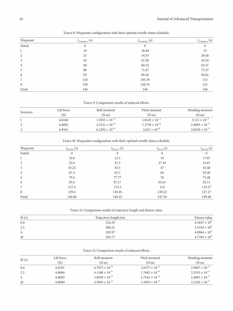

International Journal of
AerospaceEngineeringHindawiwwwhindawicom Volume 2018
RoboticsJournal of
Hindawiwwwhindawicom Volume 2018
Hindawiwwwhindawicom Volume 2018
Active and Passive Electronic Components
VLSI Design
Hindawiwwwhindawicom Volume 2018
Hindawiwwwhindawicom Volume 2018
Shock and Vibration
Hindawiwwwhindawicom Volume 2018
Civil EngineeringAdvances in
Acoustics and VibrationAdvances in
Hindawiwwwhindawicom Volume 2018
Hindawiwwwhindawicom Volume 2018
Electrical and Computer Engineering
Journal of
Advances inOptoElectronics
Hindawiwwwhindawicom
Volume 2018
Hindawi Publishing Corporation httpwwwhindawicom Volume 2013Hindawiwwwhindawicom
The Scientific World Journal
Volume 2018
Control Scienceand Engineering
Journal of
Hindawiwwwhindawicom Volume 2018
Hindawiwwwhindawicom
Journal ofEngineeringVolume 2018
SensorsJournal of
Hindawiwwwhindawicom Volume 2018
International Journal of
RotatingMachinery
Hindawiwwwhindawicom Volume 2018
Modelling ampSimulationin EngineeringHindawiwwwhindawicom Volume 2018
Hindawiwwwhindawicom Volume 2018
Chemical EngineeringInternational Journal of Antennas and
Propagation
International Journal of
Hindawiwwwhindawicom Volume 2018
Hindawiwwwhindawicom Volume 2018
Navigation and Observation
International Journal of
Hindawi
wwwhindawicom Volume 2018
Advances in
Multimedia
Submit your manuscripts atwwwhindawicom