an open service runtime environment supporting...
TRANSCRIPT
Diplomarbeit
An Open Service Runtime Environment Supporting
Autonomic Communication Principles
Lehrstuhl fur praktische Informatik. Fachbereich Informatik. TechnischeUniversitat Dortmund
in Kooperation mit
Fraunhofer-Institut fur Offene Kommunikationssysteme. FOKUS
vorgelegt von Ilya Gorodnyanskiy
1. Gutachter: Prof. Dr. Peter Buchholz2. Gutachter: Dr.-Ing. Stephan Steglich
Betreuer beim FOKUS: David Linner
September 12, 2008

Eklarung
Hiermit versichere ich, dass ich meine Arbeit selbstandig verfasst und keine anderenals die angegebenen Quellen und Hilfsmittel benutzt sowie Zitate kenntlich gemachthabe.
Essen, den 12. September 2008 Ilya Gorodnyanskiy
2
Table of Contents
Tabel of Contents . . . . . . . . . . . . . . . . . . . . . . . . . . . . . . . . 4Table of Figures . . . . . . . . . . . . . . . . . . . . . . . . . . . . . . . . . 5Table of Tables . . . . . . . . . . . . . . . . . . . . . . . . . . . . . . . . . 6
1 Introduction 71.1 Motivation . . . . . . . . . . . . . . . . . . . . . . . . . . . . . . . . . 81.2 Goals . . . . . . . . . . . . . . . . . . . . . . . . . . . . . . . . . . . . 101.3 Structure of the Document . . . . . . . . . . . . . . . . . . . . . . . . 11
2 Setting the Scene 132.1 Service Definition . . . . . . . . . . . . . . . . . . . . . . . . . . . . . 132.2 Self Organizing Wireless Networks . . . . . . . . . . . . . . . . . . . . 142.3 Properties of the Environment . . . . . . . . . . . . . . . . . . . . . . 152.4 Autonomic Communication Principles . . . . . . . . . . . . . . . . . . 182.5 Autonomous Communication Service Framework . . . . . . . . . . . . 20
3 Requirements Definition for System Architecture 233.1 Towards a Model for Open Service Runtime Environment . . . . . . . 233.2 Requirements of Service Runtime Environment . . . . . . . . . . . . . 243.3 Requirements of Service Entity . . . . . . . . . . . . . . . . . . . . . 27
4 State of the Art 294.1 Mobile Agent Systems . . . . . . . . . . . . . . . . . . . . . . . . . . 294.2 Peer-to-Peer Systems . . . . . . . . . . . . . . . . . . . . . . . . . . . 324.3 Autonomic Communication Systems . . . . . . . . . . . . . . . . . . 334.4 Summary . . . . . . . . . . . . . . . . . . . . . . . . . . . . . . . . . 36
5 Service Runtime Environment 385.1 Service Life Cycle . . . . . . . . . . . . . . . . . . . . . . . . . . . . . 395.2 Service Management . . . . . . . . . . . . . . . . . . . . . . . . . . . 415.3 Service Migration . . . . . . . . . . . . . . . . . . . . . . . . . . . . . 43
6 Service Entity 466.1 Service Description . . . . . . . . . . . . . . . . . . . . . . . . . . . . 476.2 Service State . . . . . . . . . . . . . . . . . . . . . . . . . . . . . . . 506.3 Service Communication . . . . . . . . . . . . . . . . . . . . . . . . . . 51
3

Table of Contents
6.4 User Interaction . . . . . . . . . . . . . . . . . . . . . . . . . . . . . . 55
7 Proof Of Concept 587.1 Implementation of the Service Runtime Environment . . . . . . . . . 58
7.1.1 Service Management . . . . . . . . . . . . . . . . . . . . . . . 597.1.2 Service Migration . . . . . . . . . . . . . . . . . . . . . . . . . 60
7.2 Implementation of an End-user Service . . . . . . . . . . . . . . . . . 617.2.1 Programming Language for the Service Entity . . . . . . . . . 627.2.2 Integration of the Service Entity into SRE . . . . . . . . . . . 637.2.3 Service State and Service Description . . . . . . . . . . . . . . 637.2.4 User Interaction . . . . . . . . . . . . . . . . . . . . . . . . . . 647.2.5 Application Logic . . . . . . . . . . . . . . . . . . . . . . . . . 65
8 Results and Evaluation 668.1 Results . . . . . . . . . . . . . . . . . . . . . . . . . . . . . . . . . . . 668.2 Evaluation . . . . . . . . . . . . . . . . . . . . . . . . . . . . . . . . . 70
8.2.1 Autonomic Properties of the Service Entity . . . . . . . . . . . 708.2.2 Autonomic Properties of the Service Runtime Environment . . 718.2.3 Conclusion . . . . . . . . . . . . . . . . . . . . . . . . . . . . . 72
9 Conclusion 739.1 Result Summary . . . . . . . . . . . . . . . . . . . . . . . . . . . . . 739.2 Outlook . . . . . . . . . . . . . . . . . . . . . . . . . . . . . . . . . . 75
Index 78
Attachment 78
Bibliography 83Table of Contents
4
Table of Figures
2.1 Mesh network . . . . . . . . . . . . . . . . . . . . . . . . . . . . . . . 162.2 Overview of node components . . . . . . . . . . . . . . . . . . . . . . 20
3.1 Local and global abstraction layers . . . . . . . . . . . . . . . . . . . 25
5.1 The Service Entity life cycle model . . . . . . . . . . . . . . . . . . . 41
8.1 ACSF default GUI . . . . . . . . . . . . . . . . . . . . . . . . . . . . 678.2 Service management. Default GUI . . . . . . . . . . . . . . . . . . . 688.3 Service management. RootExtractor Service is started. . . . . . . . . 698.4 Service migration. Default GUI. . . . . . . . . . . . . . . . . . . . . . 698.5 Service migration. Service was trasferred to the new location. . . . . 69
5
Table of Tables
4.1 Related works . . . . . . . . . . . . . . . . . . . . . . . . . . . . . . . 37
5.1 Service management directives . . . . . . . . . . . . . . . . . . . . . . 435.2 Service migration directives . . . . . . . . . . . . . . . . . . . . . . . 45
6.1 User Interaction directives . . . . . . . . . . . . . . . . . . . . . . . . 556.2 User Interaction directives . . . . . . . . . . . . . . . . . . . . . . . . 57
6
1 Introduction
This work contributes to the further development of service architectures for dynamicwireless networks. This is currently one of the most vibrant research areas withinmobile computing. The main challenge of this research is the design and evaluationof a comprehensive runtime environment that is capable of supporting distributed aswell as non-distributed services. These services can be seamlessly exchanged betweenmobile devices. Service migration from one device to the other can be initiatedeither by user interaction or by the service runtime environment. Moreover, theruntime environment assumes services to be adaptive and self-aware. This means inparticular that services are able to adapt their behaviour to the context provided bythe service runtime environment. Thus the runtime environment can change servicesettings such as audio volume, display colours or the amount of data a service isallowed to transfer.
The service runtime environment runs on all mobile devices irrespective of systemresources, operating systems, and application domains. So are the respective services;their implementation does not depend on a particular implementation of the runtimeenvironment.
In contrast to existing approaches the current runtime environment proposes aninnovative concept, enabling light-weight services and facilitating their rapid devel-opment. While the existing solutions assume intelligent services, which implementcomplex methods for self-awareness and adaption to the changes in the environment(e.g. monitoring of the battery charge level or the quality of wireless links betweenmobile devises) within the current service environment methods are abstracted fromthe service-level and are handled by the runtime environment.
Such a service runtime-environments for dynamic wireless networks can only ex-ist as part of a comprehensive service framework. Coincidentally, related researchwas underway at Fraunhofer, one of the largest European research organisations.Fraunhofer Institute for Open Communication Systems in Berlin is taking part ina large-scale EU-funded project (BIONETS). Work within this project is still on-going. However, a service framework designed for dynamic wireless networks hadalready been specified and partly implemented. Therefore, this framework provided
7
1.1 Motivation
the unique opportunity to embed the current work within an actual working system.
This chapter provides an overview of the subject area and depicts the structureof the thesis. The first section is dedicated to the motivation of the current work. Itintroduces the problem area and current trends, emphasises the key issues involved,that are addressed within this document. Section 1.2 details research activities tobe carried out and defines the overall goals of this study. Based on this set of goals,the thesis addresses several tasks, each of them is treated within a separate chapter.The structure of the document is in section 1.3.
1.1 Motivation
The rapid progress in mobile computing network technology in recent years has beenfueled by the continuously growing market of mobile devices. This opens promisingperspectives for bringing forward the software development in this sphere to a qual-itatively new level [1]. The performance of modern mobile devices is comparablewith those of desktop computers only a few years old. These devices are driven bysophisticated operating systems and allow the execution of a wide range of softwareapplications.
The natural property of mobile devices is their sociality towards each other and to-wards the global context. The term sociality describes the tendency to build groupswith other devices and to behave as a part of a larger system. Being connected tothe Internet, or just building up a dynamic network of several nodes is of vital im-portance for utilization of services based on principles of distributed resources, e.g.file sharing, communication, synchronization etc. which are widely spread in wiredenvironments. It is these services that will further promote the usage of mobiledevices and their integration into every-day life [1].
A highly desired property of the services in the mobile environment is their dy-namic distribution [2]. Depending on the users’ current location as well as thecurrent user needs, particular services are selected and provided to the user. Forexample, a tourist enters a museum and gets automatically an application on hisphone, which allows to pay the entrance and which then helps navigating the mu-seum’s rooms. Another example is an application that is simultaneously used byparticipants of a conference and allows the exchange of digital business cards. Ap-plication scenarios can be found in various business areas such as entertainment,business, trade, advertisement etc.
Dynamic service distribution requires the implementation of methods for service
8
1.1 Motivation
management, service distribution, service migration, that is an implementation ofa comprehensive and complex service runtime environment. A number of ques-tions concerning this environment must be addressed. What are the special require-ments to be met by the service runtime environment? What control mechanismsare needed? What kind of service concept can fulfil the challenging requirements ofthe mobile environment? Can the principles of multi-agent systems be applied tothe innovative concept of the service runtime environment?
The concept of mobile computing brings along a completely new class of chal-lenges [3]. This refers not only to the connectivity of devices using available globalcomputer network infrastructures, but also to supporting the direct and immediateconnectivity from device to device. The provision and utilization of the servicesin mobile environments, as well as the adequate design and the usability of mobileapplications. Particularly self-organizing dynamic networks, also known as mobilead-hoc networks are considered an emerging area of research. Based on unique func-tional principles, these networks pose specific requirements to distributed systemsand applications. There are two fundamental requirements that play a crucial rolefor the concept of mobile services: adaptivity and self-awareness. Whereas adaptiv-ity refers to the ability of adapting to different use cases, different situations anddifferent environments. Examples of constraints a particular situation may entailare: partial or complete absence of the networking infrastructure, unstable wire-less connection links, heterogeneity at software and at the hardware level and muchmore.
To develop innovative communication paradigms, research in the area Auto-nomic Communication (AC) currently focuses on the concepts of adaptivity andself-awareness in an attempt. Research in the area of AC assumes that existingapproaches that work in wired environments, do not necessarily meet the require-ments of dynamic wireless networks. In order to achieve good performance andenable the development of sophisticated mobile applications, self-organizing net-working structures must be able to sense their environment, detect and perceivechanges and understand the meaning of these changes. Thus, facilitating new waysof network control management, middlebox communication, service creation, servicecomposition etc. This must be based on universal and fine-grained multiplexing ofnumerous policies, rules and events to facilitate the desired behaviour of groups ofnetwork elements [4].
Hence, the main concerns of the current work are:
• A conceptualization, implementation and evaluation of a service runtime en-vironment based on principles of AC and supporting hosting of AC services
• A conceptualization of the AC services for the service runtime environment
9
1.2 Goals
The addressed issues will be studied with a limited scope, that is defined by anexisting software framework called Autonomous Communication Service Framework-ACSF, a framework designed for dynamic wireless networks developed at Fraun-hofer FOKUS in Berlin. The service runtime environment (SRE) as developed forthis thesis is to become a core component of ACSF. The choice of ACSF is mainlymotivated by its availability providing the author with the opportunity to imple-ment and evaluate theoretical considerations. Although ACSF is still in a prototypestage, it already provides a number of useful features, such as node discovery, frame-work communication protocols etc. Therefore, this study can focus on the design,implementation and evaluation of the SRE.
1.2 Goals
The scope of this work is twofold: investigating new approaches and current trends ofresearch in the domain of service architectures for dynamic wireless networks as wellas the implementation and evaluation of a particular service runtime environment(SRE) based on principles of autonomic communication (AC).
Firstly, a detailed investigation of the environment is to be conducted, in order toextract the main properties needed to characterize and categorize dynamic wirelessnetworks. This will provide a better understanding of the scope of this work and itwill also help to identify common ground as well as reference points to the paradigmof AC. It is believed that the study of the principles of AC will reveal fundamentalissues that needed to be taken into consideration during the conceptualisation ofthe SRE.
The prime goal of this thesis is the design, the development and the evaluationof a SRE comprising all functional components, needed to enable service manage-ment and service migration between networking nodes. The SRE should supportdistributed as well as non-distributed services. The SRE must deploy services on-the-fly. The service migration should not meet any assumptions concerning targetdevice and target SRE. That means in particular, that the service implementationshould not depend on the implementation of a particular SRE. The most importantSRE requirement, and the actual challenge of this work, is to enable light-weight butat the same time adaptive and self-aware services. That means that the complexmethods for self-awareness and adaptivity to changes in the environment should beabstracted from the service-level and be handled by the SRE. The services are thenrequired to be adaptive only to the context provided by the SRE. An appropriateservice concept should be detailed discussed in this work, in order to provide clear-ness of the SRE concept. The conceptualisation of the actual system monitoringmechanisms as well as their implementation is not the part of the current research.
The development of the SRE consists of modelling and implementation activities.The modelling activities are concerned with the service interface, i.e. the interface
10
1.3 Structure of the Document
used by the SRE to control service behaviour (service life cycle, service migration,service communication), and with actual methods and mechanisms to enable servicemanipulations.
The conceptual part involves, among others, the analysis of relevant existingtechnologies and research projects. Particularly, software architectures, based onautonomic communication principles, mobile agents, peer-to-peer communicationparadigms and cross platform programming appear to be relevant for the scopeof this work. Advantages and shortcomings of the existing approaches are to beinvestigated and discussed in accordance to the goals of this work.
The implementation is conducted as a proof-of-concept. It comprises the softwaredevelopment and the discussion of technologies used within the development. Theresulting SRE components should be then evaluated. An end-user service is to bedeveloped to demonstrate the internal interaction between the various functionalcomponents of the SRE. The results of evaluation should be afterwards comparedwith the initial theoretical assumptions.
1.3 Structure of the Document
Overall, the current document is subdivided into nine chapters. Each of them rep-resents a stepping stone towards achieving the goals as set out in the previousparagraph.
The first chapter provides an overview of the general problem area, reports oncurrent trends of research within the domain and refines the academic and practicalgoals of this thesis.
The second chapter sets the overall scene and refers to relevant literature in orderto provide a comprehensive foundation for later assumptions, theories and conclu-sions. The chapter starts with definition of the terms service. An investigationof dynamic wireless network technologies is considered essential to introduce theparadigm of ad-hoc networks. It also motivates the decision to utilise mesh net-works as the main application area for the SRE and its services. Furthermore,this chapter outlines the conceptualisation of functional components of the SRE byanalysing the specific requirements and properties of the environment. The analysisof the environment is followed by an introduction of the autonomic communicationparadigm, which is believed to be highly suitable to cater for the next generation ofcomputer networks. Finally, chapter 2 illustrates the architecture of ACSF and themeaning of the SRE in its context.
Chapter 3 investigates and analyses the requirements of the SRE and of its ser-vices. This is done in the context of ACSF in order to achieve a comprehensiveoverview of the entire distributed system. The definition of actual requirements isbased on the properties of the environment and the principles of autonomic com-munication. This is seen as an important step towards designing an abstract model
11
1.3 Structure of the Document
of the SRE. It is argued, that due to the similarities of the paradigms of service-orientation and mobile agents, the conceptual model of the SRE can borrow fromthe concept of multi-agent systems.
Chapter 4 conducts a review of different existing systems and various recent re-search projects that address similar problems by applying concepts derived from theareas of multi-agent systems, peer-to-peer networking and autonomic communica-tion However, it turned out that all solutions could partly meet the requirements aspreviously defined.
Chapter 5 deals with modelling the SRE. The concept of service life cycle is theentry point for the discussion of the functional components that the SRE mustprovide. Based on this discussion two essential components are defined, servicemanagement and service migration,
Chapter 6 is devoted to the modelling of the service entity. This model definestwo obligatory service components, service description and service state, as well astwo basic service capabilities: service communication and user interaction. Thecomponents and the capabilities of services are discussed in detail in this chapter.
Chapter 7 reports on the implementation of the SRE and service models. Theimplementation of the SRE and of an exemplary service entity are separately handledin respective sections. These sections focus on a discussion of relevant technologiesand available development tools.
Chapter 8 analyses results achieved and evaluates the AC properties of the SREand its services. Evaluation issues comprise the comprehensiveness and accuracy,technological limitations, error rate and a list of unpredicted problems. Finally, theautonomic properties of the SRE are analysed in compliance with the requirementsas defined in chapter 3.
Chapter 9 provides a summary of the current work. Theoretical as well as practicalresults as achieved are outlined. Goals, methods and results are compared andinterpreted. Finally, an outlook of future activities concerning the SRE and ACSFis provided.
12
2 Setting the Scene
The realisation of the goals as defined in section 1.2 requires a clear definition of thescene. Background information based on a review of literature plays a fundamentalrole and serves as a reference point for the motivation for particular approaches, forstatements to be argued and for design decisions made in this work.
First of all it is essential to give a formal definition for the term service, in orderto avoid misunderstanding and confusion. This is handled in the first section of thischapter. The second section investigates the main characteristics of the environ-ment. The main application domain of the SRE is self-organizing dynamic wirelessnetworks. There are several members in this networking family, each of them charac-terized by particular properties depending on the specific application scenario. Thissection gives a review of ad-hoc networking concepts and technologies. It also mo-tivates the limitation of the current investigation to only one networking paradigm,namely mesh networks. The third section describes in detail characteristic prop-erties of the environment. This is an important step towards understanding theproblem scope and the autonomic communication (AC) principles. The fourth sec-tion introduces the AC paradigm in detail. The final section of this chapter dealswith the architecture of the Autonomous Communication Service Framework. Theintroduction of existing components gives an overview of the functional abilities ofthe system and explains the required complexity for the integration of the SRE intothis framework.
2.1 Service Definition
A Service is also referred to as a Service Entity. It is a fragment of code whichrequires a Service Runtime Environment (SRE) for its execution. The Service lifecycle and Service activities are controlled entirely by the SRE. Depending on thecomplexity of the application, a Service can be stateless or stateful. The state canbe understood as a context in which a particular Service runs and can be defined asa scope of values, which are relevant for performing any actions by the Service.
In general there are two types of Services, which SRE aims to support: composedand non-composed ones. The instances of non-composed Services are independentin their nature and do not rely on other Services for their successful execution.In contrast, composed Services depend on a set of particular Services, which areorchestrated into a larger Service. The parts of a composed Service can run on
13
2.2 Self Organizing Wireless Networks
different nodes.Services can migrate from one networking node to another. The migration process
can be initiated only by the SRE. Whether a particular Service is transferred withits state or without it depends on a particular situation. This decision is also metby controlling mechanisms of the SRE.
An essential component of every Service is its description. Service descriptioncontains information, which can be useful for a human, e.g. the manufacturer, thename and the version of the Service, how to use the Service etc. Besides this Servicecan contain details for the dynamic Service orchestration, which can be performedautomatically and transparent for the user.
Service description plays an important role for the Service discovery and for theService migration processes. Due to the environmental characteristics the mecha-nism for the Service distribution over the network differs from the conventional Ser-vice discovery in networks with pre-existing infrastructure. In dynamic networks,where the network topology can change any time, the mobile nodes should exchangeinformation about the Services they are currently hosting. The meta-information inthe Service description helps to organize Services within specific taxonomies or toperform rating.
2.2 Self Organizing Wireless Networks
The concept of self organizing wireless networks such as mobile ad-hoc networks(MANETs), wireless sensor networks (WSN) and wireless mesh networks, has alarge potential and promising perspectives for providing an individual with servicesand context information under the conditions of a total or a partial inaccessibilityof the pre-existing network infrastructure.
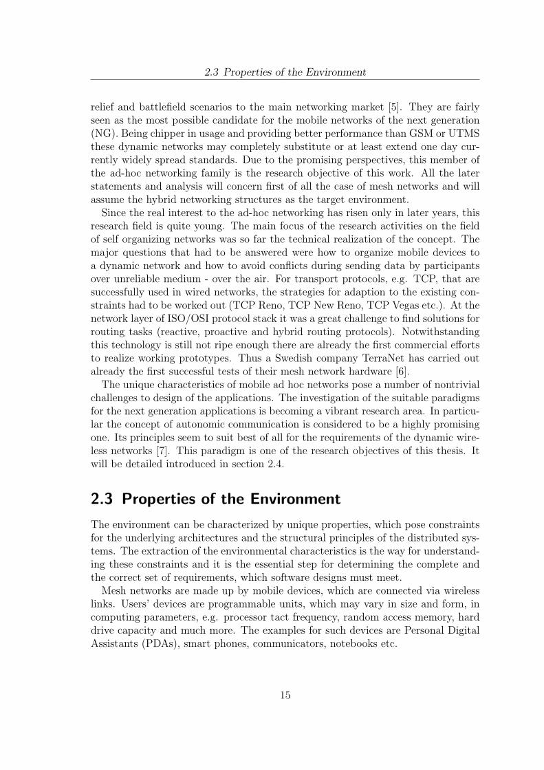
The classical MANETs are completely self organizing and are very attractive forparticular scenarios, e.g. disaster recovery, vehicle-to-vehicle communications, homenetworking etc. Originally, the idea of the dynamic networks came from the militarysector. Nowadays MANETs have very limited penetration as a network technologyfor mass-market deployment. The more pragmatic scenario is the utilisation ofmulti-hop ad-hoc networks as a flexible and ”low cost” extension of the Internet.Unlike MANETs, where no infrastructure exists and every node is mobile, in a meshnetwork there is a set of nodes, the so called mesh routers, which are stationary andform a wireless multi-hop ad-hoc backbone. Some of the routers are attached to theInternet, and provide connectivity to the whole Mesh Network. Mesh routers arenot users’ devices. They represent the infrastructure of a mesh. Routing protocols,which run on mesh routers, allow the backbone to be self configuring, self healing,and easy to set up. Client nodes connect to the closest mesh router, and use thewireless ad-hoc backbone to access the Internet [5].
Mesh networks are moving multi-hop ad-hoc networks from emergency-disaster-
14
2.3 Properties of the Environment
relief and battlefield scenarios to the main networking market [5]. They are fairlyseen as the most possible candidate for the mobile networks of the next generation(NG). Being chipper in usage and providing better performance than GSM or UTMSthese dynamic networks may completely substitute or at least extend one day cur-rently widely spread standards. Due to the promising perspectives, this member ofthe ad-hoc networking family is the research objective of this work. All the laterstatements and analysis will concern first of all the case of mesh networks and willassume the hybrid networking structures as the target environment.
Since the real interest to the ad-hoc networking has risen only in later years, thisresearch field is quite young. The main focus of the research activities on the fieldof self organizing networks was so far the technical realization of the concept. Themajor questions that had to be answered were how to organize mobile devices toa dynamic network and how to avoid conflicts during sending data by participantsover unreliable medium - over the air. For transport protocols, e.g. TCP, that aresuccessfully used in wired networks, the strategies for adaption to the existing con-straints had to be worked out (TCP Reno, TCP New Reno, TCP Vegas etc.). At thenetwork layer of ISO/OSI protocol stack it was a great challenge to find solutions forrouting tasks (reactive, proactive and hybrid routing protocols). Notwithstandingthis technology is still not ripe enough there are already the first commercial effortsto realize working prototypes. Thus a Swedish company TerraNet has carried outalready the first successful tests of their mesh network hardware [6].
The unique characteristics of mobile ad hoc networks pose a number of nontrivialchallenges to design of the applications. The investigation of the suitable paradigmsfor the next generation applications is becoming a vibrant research area. In particu-lar the concept of autonomic communication is considered to be a highly promisingone. Its principles seem to suit best of all for the requirements of the dynamic wire-less networks [7]. This paradigm is one of the research objectives of this thesis. Itwill be detailed introduced in section 2.4.
2.3 Properties of the Environment
The environment can be characterized by unique properties, which pose constraintsfor the underlying architectures and the structural principles of the distributed sys-tems. The extraction of the environmental characteristics is the way for understand-ing these constraints and it is the essential step for determining the complete andthe correct set of requirements, which software designs must meet.
Mesh networks are made up by mobile devices, which are connected via wirelesslinks. Users’ devices are programmable units, which may vary in size and form, incomputing parameters, e.g. processor tact frequency, random access memory, harddrive capacity and much more. The examples for such devices are Personal DigitalAssistants (PDAs), smart phones, communicators, notebooks etc.
15
2.3 Properties of the Environment
Figure 2.1: Mesh network
Mesh networking paradigm can be realised on the basis of various wireless net-working technologies like 802.11 family, Bluetooth, ZigBee, etc. In praxis there isa tendency towards utilization of IEEE 802.11. Thus there is a draft of the IEEE802.11 s standards, which defines how wireless devices can interconnect to createa mesh network. Currently, the networking modules based on the standards IEEE802.11 a/b/g are integrated in most of the modern mobile devices facilitating thepractical usage of the mesh networks already now.
The utilisation of the wireless technologies and the dynamism of the networktopology entail a complex of problems, which are to be considered at the applica-tion layer of the protocol stack. The behaviour of every certain network node affectsthe network properties and implicitly the behaviour of other nodes. For example, aparticular node B has a low battery charge. Assuming another node A is download-ing recklessly a large file and involves node B to access the Internet. In this scenarioB can be burdened so much, that it causes the fall out of the node and the changein the network topology. Thus not only node B, but also node A is affected, becauseit is disconnected from the networking resources.
As already mentioned in the introduction chapter the networking elements couldbenefit from the autonomic communication paradigm. The ability of any particularnetwork element to adapt its behaviour adequately to the environmental changesmakes the network to a self-behaving system with properties such as self-healing,self-configuration, self-organization, self-optimization and so forth - the so called
16
2.3 Properties of the Environment
self-* properties. These self-aware properties of the distributed applications basedon comprehensive system monitoring mechanisms is the goal of the Service RuntimeEnvironment (SRE).
Besides the complex of considerations regarding structural network organiza-tion, there is another significant practical issue, namely heterogeneity of the self-organizing networks. The differences at the hardware level determine partly thetype of operating system and a set of programs that can run on these devices. Thusa Mesh Network can be made up of units driven by Windows family operation sys-tem (Windows XP, Windows Mobile etc.), Unix family operation system, Symbianand much more. Since the mesh networking paradigm sets no strict constraintsregarding hardware and software, the networks may have a highly heterogeneouscharacter. One of the prime challenges in the domain of dynamic wireless networkis to overcome the heterogeneity and to enable the development and the execution ofprograms independently from the software and hardware equipment of a particulardevice. The cross platform concept of the designing systems is one of the require-ments, facilitating the transparent and convenient way for software development andsoftware usage as well.
The next environmental characteristic is application types which are supported bythe underlying networking technology. Wireless technologies based on IEEE 802.11standards enable real time as well as non real time services. This opens the facilitiesfor development of the asynchronous services, like Email, as well as synchronousones like instant messaging, video streaming etc.
Like in the wired networks, the data exchange between mobile nodes is alwaysfirmly coupled with the security and privacy issues. The threats of malicious codeor affected privacy are significant aspects, which have to be taken into considerationwhen designing services for the current environment.
The most important environmental characteristics are summarized once again inthe list below:
1. Application domain: mobile mesh networks.
2. Mobile devices may differ significantly from each other both in hardware andsoftware capacities.
3. Autonomic communication paradigm is the natural way for the architecturalorganization of the software solutions in dynamic wireless network.
4. Wireless technologies support the realisation of real-time and non-real-timeservices.
5. Data exchange between mobile nodes entails threats of security nature.
17
2.4 Autonomic Communication Principles
2.4 Autonomic Communication Principles
The term autonomic communication(AC) addresses a considerable area of researchand industrial interest. Its results are turned to a deep foundational re-thinking ofcommunication, networking, and distributed computing paradigms, to face the in-creasing complexities and dynamics of modern network scenarios [8]. The ultimatevision of autonomic communication researches is that of a networked world, in whichnetworks, associated devices and services will be able to work in a totally unsuper-vised - i.e., autonomic way, being able to self-configure, self-monitor, self-adapt, andself-heal [9]. By analogy to the human autonomic nervous system, which regulateshomeostatic functions without conscious intelligent control, autonomic communica-tion seeks to simplify the management of complex communications structures andreduce the need for manual intervention and management [7].
AC is closely related to autonomic computing, which is often described as self-CHOP (self-configuration, -healing, -optimisation, and -protection). Despite theirevident similarities, there are significant differences between autonomic computingand communication. While AC is more oriented towards distributed systems andmanagement of network resources at both the infrastructure and the user levels,autonomic computing is more directly oriented towards application software andmanagement of computing resources [7]. Nevertheless both research areas recognizethe need for decentralized algorithms and control, context-awareness, novel program-ming paradigms, end-to-end privacy management, and comprehensive evaluation inorder to increase stability and efficiency of designed systems.
Self-organization, which lies at the base of the AC paradigm, is characterized byfollowing requirements [10]:
1. Self-awareness. An autonomic system must know the components it consistsof, current status, ultimate capacity, and all connections to other systems togovern itself. Besides that, the system has to be aware of resources it currentlypossesses, also of those, which can be lend or borrowed, shared or should beisolated.
2. Self-[re]configuration. An autonomic system must configure and reconfigureitself absolutely dynamically according to any involving situation. One speaksoften of so-called zero-effort deployment.
3. Self-optimisation. This property requires from an autonomic system to opti-mize and to fine-tune its activity in order to achieve predefined system goalsin a best way.
4. Self-healing. An autonomic system must be able to discover problems, recoveritself after system crashes and look for alternative usage of resources, if it keepsthe system functioning smoothly.
18

2.4 Autonomic Communication Principles
5. Self-protection. An autonomic system must detect, identify and protect it-self against various types of attacks to maintain overall system security andintegrity.
6. Self-adaption (context). An autonomic system must know its environment andthe context surrounding its activity, and act accordingly.
7. Self-description (openness). While independent in its ability to manage itself,an autonomic system must function in a heterogeneous world and implementopen standards.
8. Self-implementation. It must marshal I/T resources to shrink the gap be-tween the business or personal goals of the user, and the I/T implementationnecessary to achieve those goals – without involving the user in that imple-mentation.
The enumerated properties above let characterize the AC by the following formula[11]:
AC Key Issues = Adaptivity & Self-awareness
These two properties are the fundament of this paradigm and express the vision ofthe next generation networks, which is to be found in numerous technical literature.The next question, which is to be answered, is what are the actual benefits? Whatare advantages of the AC and the next generation networks over static networkarchitectures of nowadays?
First of all it is the cost factor. The realisation of the desired vision of being al-ways online anytime and at any place based on the traditional networking conceptsis coupled with great complexity for providing the networking infrastructure andservice management. During self-organizing networks together with distributed ap-plications based on principles of Autonomic Communication offer a chipper solution,the current approaches cause enormous costs for service providers and customers aswell.
Apart from the cost factor AC paradigm promises a better service quality. Self-adaptivity property of the next generation networks allows adequate handling ofeven unpredictable situations. The centralized mechanisms lack this flexibility andcan guarantee the correct handling of only certain standard scenarios.
Another beneficial issue is the new spectrum of applications, which become possi-ble due to the new paradigm. That does not always mean, that particular applicationscenarios cannot be realised by means of centralized mechanisms. However, the re-quired complexity can be in certain cases unproportional to the expectations of theservice developers and service customers [12].
Hence, the perspectivity of the innovative AC paradigm provides the current workwith additional motivation to investigate its foundational principles and to studythem in practical application.
19
2.5 Autonomous Communication Service Framework
2.5 Autonomous Communication Service Framework
The current section introduces the architecture of Autonomous CommunicationService Framework (ACSF). This framework will be later applied as assistant toolfor the evaluation of the technical realisation of the Service Runtime Environment.
ACSF is a development of Fraunhofer Institute FOKUS in Berlin. The goal ofthe project is to offer a universal software platform, facilitating service executionand service exchange between mobile devices in dynamic wireless networks. Theterm universal means in this context that the platform takes into account existingconstraints of the environment and offers an adequate solution for particular tasks.This project derivates from the larger European project called BIONETS [13] andhas inherited some of its concepts.
The prime operating entity in terms of ACSF is a Service Entity. Service Entitiesare to be understood according to the Service definition in section 2.1. Services canbe exchanged between ACSF instances or can be downloaded from the Internet.ACSF is designed for the mesh networks and assumes in general the existence of astable global network kernel.
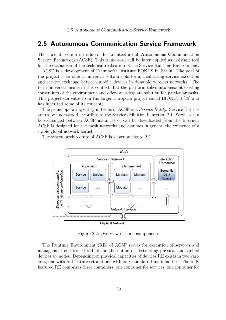
The system architecture of ACSF is shown at figure 2.2.
Figure 2.2: Overview of node components
The Runtime Environment (RE) of ACSF serves for execution of services andmanagement entities. It is built on the notion of abstracting physical and virtualdevices by nodes. Depending on physical capacities of devices RE exists in two vari-ants, one with full feature set and one with only standard functionalities. The fullyfeatured RE comprises three containers, one container for services, one container for
20
2.5 Autonomous Communication Service Framework
management entities, so called Mediators, and one container for Interaction Models.Application and Management containers build up the environment, so called ServiceFramework in which Services are executed and managed.
Application container
Application container is of special interest for this master thesis, because it rep-resents a place holder for the Service Runtime Environment (SRE), which will beconceptualised and developed in the current work. The application container shouldprovide the structural organization of the executing Services. It must realise mecha-nisms regulating Service life cycle. Preparing a particular Service for migration andreceiving Service from other nodes are also the tasks of the application container.
Management Container
While Services realise the application logic, Mediators perform all node-related or-ganisational tasks. They provide mechanisms for monitoring the environment andthe internal processes of ACSF node. They are able to evaluate the gathered mon-itoring information and adequately react to the changes. Particular Mediators caninteract with the SRE and use its management mechanisms to improve the systemperformance.
Unlike Service Entities Mediators are pre-installed units and cannot be dynami-cally exchanged between ACSF instances. Every ACSF instance can be equippedwith its own set of Mediators. In dependence on the device capacities or the userpreferences ACSF can be configured by adding or deleting Mediators.
Interaction Framework
The Interaction Framework contains implementation of predefined communicationpatterns, the so called interaction models, such as Publish/Subscribe, DHT, or Se-mantic data Space. The interaction framework abstracts the implementation ofinteraction models from the upper components. Like the Mediators, the InteractionModels have to be pre-installed on each ACSF node. Depending on the involvingsituation Mediators can choose one of the communication patterns to communicatewith Mediators at the other network nodes.
Network Interface
Network Interface Layer of the ACSF architecture represents a wrapper around thecommunication channels. It enables the access to the other nodes over the networkand makes this access transparent to the functional components of ACSF. NetworkInterface offers a set of operations on resources, according to a principle called CRUD
21

2.5 Autonomous Communication Service Framework
(create, read, update, delete). In the current implementation HTTP protocol is usedfor the realisation of this concept.
22
3 Requirements Definition forSystem Architecture
The previous chapter gave an overview of the application environment, its charac-terising properties and the concept of autonomic communication, as the foundationof the self-organising networks. These background facts make it possible to get fromthe general awareness of the problem area to the discussion of the service runtimeenvironment (SRE) concept. The SRE concept is a necessary step towards a SREmodel and a prerequisite for the definition of system requirements.
The SRE concept is discussed in section 3.1. As it will be shown there, the defini-tion of the system requirements should assume two views. Adaptivity and awarenessare to be expected in the global context as well as in the execution context of Services.That is why the set of requirements is divided into two classes, Service Runtime En-vironment specific requirements and Service Entity specific requirements, which willbe discussed in respective sections.
3.1 Towards a Model for Open Service RuntimeEnvironment
Based on the autonomic communication (AC) principles and the properties of theenvironment, this section introduces the first step towards a model for the SRE. It isessential to investigate now, whether the ecology of Services can be considered as asort of a complex agent society and whether the SRE can borrow the distinguishingmarks of multi-agent systems.
The similar question is detailed discussed in [9]. This paper focuses on AC ser-vices with the goal of ”trying to synthesize the key desirable characteristics thatone should expect from a general-purpose component model for autonomic commu-nication services and the contributions that can come from the agent community”.It is claimed in this work, that ”an agent model can be the most suitable answerto the challenging requirements of autonomic communications. Nonetheless, pastagent models do not fulfil all the requirements”. Furthermore the authors of thispaper explain, that the component model for the multi-agent systems should ”beable to enforce autonomic behaviour in both the forms of self-adaptation and self-organization, able to handle ”‘situatedness”’ in complex knowledge environments,
23
3.2 Requirements of Service Runtime Environment
and should tolerate scalable forms of dynamic aggregation”. Hence, AC services canbe seen as advanced agents fulfilling the principles of adaptivity and self-awareness.
On the one hand the SRE should be like most of the execution environmentsfor mobile agents, just a container for Services supporting primitive operations likestarting, stopping, terminating etc. On the other hand it should be an intelli-gent environment for smart entities. Different as in [9], where agents/service areassumed to be of two kinds, very simple reactive agents and more heavy-weight”intelligent” self-adaptive agents, this work envisions an innovative concept of onlylight-weight Services. The idea is to realise most of the adaptivity and self-awarenesscapabilities of AC services as a part of the SRE. For example the SRE could con-tain self-protection mechanisms enabling safe communication between Services, self-implementation mechanisms enabling automated Service discovery for aggregationof composed Services etc.
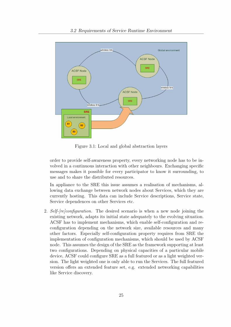
For the realisation of this concept Services should be isolated from the directcontacts to the global environment. Instead of that each Service should implementlogic for handling only a standard set of changes, which are injected by SRE’scontrol mechanisms. These injections are results of projection of the global changesin the environment into the local context. The SRE monitors the environment andtransforms the monitoring information into standard control directives, which canbe interpreted by every Service. Figure 3.1 illustrates these two abstraction levels.The global context is given by a network of ACSF Nodes with integrated SREs. Thelocal context is provided by the SRE.
Such a concept is assumed to have two major benefits. One of them is that Serviceapplication logic stays simple and does not include any sophisticated monitoringmechanisms. The other advantage is that due to uniform set of possible local eventsdefined by the SRE, Services must not be modified, if, for example, they shouldbe used in dynamic networks with other organisational principles than mobile meshnetworks. Modifications are only required at the SRE.
The described concepts for the SRE and Services pose particular requirementsto functional components of the SRE as well as to the respective Service Entities.These requirements are defined in the next sections.
3.2 Requirements of Service Runtime Environment
Requirements definition is based on eight principles of autonomic communication(AC) as discussed in section 2.4 and the concept of the service runtime environment(SRE) as outlined in section 3.1. The meaning of the AC principles for the designof the SRE architecture is discussed below. It is reasonable at this point to look atthe Service Runtime Environment in the context of ACSF, because it will provide abetter understanding of the cooperation, which is required from the network nodes.
1. Self-awareness. Every ACSF instance is a part of a distributed system. In
24
3.2 Requirements of Service Runtime Environment
Figure 3.1: Local and global abstraction layers
order to provide self-awareness property, every networking node has to be in-volved in a continuous interaction with other neighbours. Exchanging specificmessages makes it possible for every participator to know it surrounding, touse and to share the distributed resources.
In appliance to the SRE this issue assumes a realisation of mechanisms, al-lowing data exchange between network nodes about Services, which they arecurrently hosting. This data can include Service descriptions, Service state,Service dependences on other Services etc.
2. Self-[re]configuration. The desired scenario is when a new node joining theexisting network, adapts its initial state adequately to the evolving situation.ACSF has to implement mechanisms, which enable self-configuration and re-configuration depending on the network size, available resources and manyother factors. Especially self-configuration property requires from SRE theimplementation of configuration mechanisms, which should be used by ACSFnode. This assumes the design of the SRE as the framework supporting at leasttwo configurations. Depending on physical capacities of a particular mobiledevice, ACSF could configure SRE as a full featured or as a light weighted ver-sion. The light weighted one is only able to run the Services. The full featuredversion offers an extended feature set, e.g. extended networking capabilitieslike Service discovery.
25
3.2 Requirements of Service Runtime Environment
3. Self-optimisation requires mechanisms, which enable the cooperation of allACSF instances, especially cooperation of their SREs, targeted at improve-ment of the system performance. Such mechanisms can control communica-tion traffic between nodes, redistribute resources and roles in the network etc.These mechanisms can even initiate Service migration, if for example a betterperformance is expected at the neighbour node. In particular scenarios themigration is coupled with an obligatory transfer of the Service state, whereasin other cases only a code migration is required.
Self-optimisation property reveals a similarity to the self-reconfiguration. In-deed, in both cases a certain node adapts its behaviour. The difference is thatself-configuration envisions a particular node passively to accept the predeter-mined parameters, while in the self-optimisation process every ACSF instanceis actively involved and contributes to the common goal.
4. Self-healing property provides in particular ACSF instances with ability toreorganise the distributed system, when a particular network node/ACSF in-stance leaves the network. The reorganisation performs healing of the com-munication process between nodes and the possible misbalance in distributionof resources. In such scenarios SREs should be able to update the informationon Services, which are present in the network and if required to redistributesome ServiceEntities over the network to achieve the former system stability.
5. Self-protection. ACSF instances have to implement mechanisms, which areable to protect the system against potentially malicious system elements.These mechanisms have to detect the suspicious behaviour of the network-ing nodes, to support safe communication, to provide functionalities for iden-tification and authorization etc. Self-protection requires from the SRE therealisation of mechanisms controlling code distribution and communicationprocess with other SRE instances.
6. Self-adaption property provides the designing system with ability to be awareof the context it is executed in. The monitoring of the changes in the environ-ment is a necessary routine for successful and stable work of ACSF and SREas well. In general, monitoring data like usage of network channels, computingcapacities of mobile devices or power consume can help to improve stabilityand efficiency of the system. The most important changes in the environmenthave to be registered and analysed by ACSF. Some of these changes, whichare relevant for Service execution have to be forwarded to the SRE as informa-tion units for further evaluation, or as control instructions for an immediateexecution.
7. Self-description. The usage of open standards is the only way to provide theuniversality of the ACSF design. A system concept, which is free from any
26
3.3 Requirements of Service Entity
assumptions concerning target hardware and software environment, enablesespecially the realisation of ACSF and the SRE for any platform. For examplea particular ACSF instance implemented in a C# programming language cancoexist and interact with instances implemented in Java, Python etc.
8. Self-implementation. One of the challenges of ACSF is the support of com-posed Services. The Service composition must be carried out without userinvolvement. The effective interaction between SREs is the key to the realisa-tion of this concept.
3.3 Requirements of Service Entity
Services represent a lower level of abstraction. While adaptivity and self-awarenessof ACSF instances and their SREs are required in the global context as outlined inprevious section, Services must be adaptive and self-aware in the context providedby the SRE. Being hosted at a particular network node, Services act as autonomousentities. They also sense the environment they are executed in, and react accord-ingly to the occurring changes. However, the character of relationship betweenServices and the SRE differs from that at the global level. The SRE plays a role of asupervisor. It prescribes the Service Entities when and how they have to adapt. Par-ticular control directives are forwarded through a common Service interface, whichevery Service has to implement. Obeying these directives, every Service implicitlycontributes to the achieving of the desired node behaviour in the global context.
In following the meaning of the self-organizing principles as introduced in section2.4 for Service Entities is discussed.
1. Self-awareness. A Service is an autonomous entity. Its internal executionprocesses are encapsulated and are not directly accessible from outside. Onlythe Service Entity itself is aware of them and can influence them.
2. Self-configuration. Services have to implement mechanisms, enabling its con-figuration and reconfiguration. The access to these mechanisms should begranted to the SRE. The examples for possible configuration parameters areuser interaction mode (audio or visual), volume of the played audio files, QoSparameters, some variable values etc.
3. Self-optimisation. A ServiceEntity can realise more than one algorithm forexecution of a particular task. In dependence on configuration parameters theautomated switch between these algorithms can be performed. For example, ifa particular Service performs data sort, it can switch between various sortingalgorithms in order to improve its performance.
27
3.3 Requirements of Service Entity
4. Self-healing.This property requires from Services to be able to recover theirexecution state after, for example, system crash or after migration to anotherexecution environment.
5. Self-protection. This property can be seen as an optional. The prime pro-tection mechanisms should be realised within SRE. However, the applicationlogic of a particular Service can implement additional mechanisms like warningduring transmission of private data, login and password for access of particularfunctionalities of the Service etc.
6. Self-adaption property is provided by the configuration mechanisms. The SREcan any time assign a particular configuration to a Service. Based on theparameters values the Service Entity can adapt its behaviour.
7. Self-description. This property requires the utilisation of open standards forService development. The final goal is that Services can be executed in all or atleast in most systems. Service Entities should not depend neither on particularimplementation of the SRE nor on the software environment of a particulardevice. The examples of open standards could be XML for generating of crossplatform GUIs, ECMA JavaScript for the realisation of the application logicetc.
8. Self-implementation. This property requires transparency for the user whilebuilding up composed Services. The utilisation of composed Services shouldnot vary from the usage of non-composed Services.
28
4 State of the Art
Previous chapter has introduced the concept of the SRE and has defined the re-quirements for the SRE and respective Services. Based on these results it becomespossible to discuss existing projects and solutions, which address the same problemarea and fulfil some of the defined requirements. The comparison of different solu-tions will help to identify the common tendencies and to consider the advantagesand disadvantages of existing projects in the current work.
Although there are numerous discussion papers and tutorials on autonomic com-puting, networking and communication there is still a lack of guidance on how todefine and to implement autonomic communication systems. There is neither anaccepted definition of what an autonomic network is, nor a definition of what auto-nomic management or autonomic communication is [14]. That is why it is hardlypossible to conduct the-state-of-the art analysis referring to any accepted standards,established approaches and stereotyping way of thinking. The reference points inthe current analysis are only SRE concept and the set of requirements defined insection 3.
As it was shown in section 3.1 the SRE will be conceptualised as an advancedmulti-agent system and its Services will remind of advanced mobile agents. Thatis why it is reasonable to look firstly at the most known agent-based architectures.Solutions for agent hosting, agent migration and agent management are of particularinterest. Mobile agent systems are discussed in section 4.1.
It is expected, that relevant works can be also found in Peer-to-peer networking.The techniques which are applied there for peer discovery, self-organization into peergroups, advertising etc. can be used for the realisation of self-awareness propertiesof AC Services. These works are discussed in section 4.2.
Section 4.3 introduces some known AC systems. However, most of these projectsare still in development and will be completed in one or two years. That is whythere is no empiric data yet and it is only possible to discuss the conceptual issuesof these works.
4.1 Mobile Agent Systems
The first mobile agent system is IMB Aglets. This is one of the earliest and widelyaccepted agent systems, which was developed at IBM research labs.
29
4.1 Mobile Agent Systems
IMB Aglets
The name Aglet is composed of two terms Agent and Applet and reflects the natureof Aglets. Aglets are Java objects that can move from one host to another. Theycan any time make a decision to halt their execution, dispatch to a new location andre-start executing again by presenting their credentials and obtaining access to localservices and data [15]. The Aglets are characterized by two important properties:Object-passing and Autonomous Execution. Object-passing means that when amobile agent is transferred, the whole object is passed; that is, its code, data, state,and travel itinerary are passed together. Autonomous Execution says that a mobileagent possesses all the sufficient information to decide what to do, where and whento go [16]. Aglets runtime environment defines only the most necessary managementmethods to control agent life cycle, mobility, travel, itinerary, and security.
In contrast to IBM Aglets system SRE concept does not assume AutonomousExecution for AC Services. Services rely on the mechanisms within SRE, whichprovide a particular Service with abilities to adaptation and self-awareness.
A significant shortcoming of Aglets framework is its binding on Java VirtualMachine. That means that only that equipment can make use of Aglets, whichhas software and hardware prerequisites for running JVM.
Another mobile agent system often referenced in the technical literature, is AgentTcl, which was developed at Dartmouth College.
Agent Tcl
The main programming language of Agent Tcl is Tcl, but it provides a frameworkfor incorporating additional languages like Java. Agent Tcl architecture consistsof four levels. The lowest level is an API for the available transport mechanisms.The second level is a server that runs at each node. The server is responsiblefor management tasks like accepting and registering new agents, keeping track ofagents, authenticating the identity of the agent’s owner, passing the agent to theappropriate interpreter etc. The third level is the level of interpreters for supportinglanguages. Apart from the actual interpreter this level must include security modelfor migrating agents, state module enabling restoring of the agent state and theAPI that interacts with the server to handle migration, communication and checkpointing. The top level of the system architecture is the agent itself [17].
A great advantage of this system is its ability to execute mobile agents written innumerous scripting languages. The usage of several interpreters makes the systemflexible and makes the agent implementation independent from the realization of theagent framework. This fact meets a desired self-description property (see section 3.3)
30
4.1 Mobile Agent Systems
The next related work is a German project Ara.
Ara. Agents for Remote Action
Ara agent system was developed at the University of Kaiserslautern. In many aspectsAra’s concept is very close to that of the Agent Tcl system. Especially, Ara doesnot prescribe an agent programming language. Like Agent Tcl it supports theintegration of several interpreters [18].
Ara realises a good concept for the networks with limited bandwidth. The onlyway of communication between mobile agents in Ara is the asynchronous messageexchanging. Ara’s concept encourages mobile agents to meet up at some host andinteract there in a client-service manner rather then to communicate over the net-work.
However, such a concept cannot be taken for the SRE. Except for particularscenarios, inter-node communication is the key mechanism enabling the fulfilling ofthe requirements in sections 3.2 and 3.3.
The next mobile agent system, which is worth introducing here, stands outdue to the fact, that it is the first OMG MASIF and FIPA 97-conformant agentplatform[19].
Grasshopper
Grasshopper system was developed by GMD FOKUS and IKV++[20]. Grasshopperis compliant with the agent standard MASIF. Unlike Ara it supports multiple com-munication protocols such as Remote Method Invocation (RMI), RMI SSL, PlainSocket, Plain Socket/SSL, and IIOP. Supported communication modes include syn-chronous, asynchronous, dynamic, and multicast [21].
Grasshopper’s agents are Java-objects. The agent framework in terms ofGrasshopper is called agency. An agency may contain either static or mobile agentsand may be subdivided in more than one place. Agent framework contains oncespecial service, called region registry service. This service manages information onagents, agencies and places. Using region registry an agent can find out a locationof a particular service and migrate there to benefit from local interactions [21].
Unlike agent systems that were introduced above the next related project wasdesigned for Mobile Ad-Hoc Networks.
31
4.2 Peer-to-Peer Systems
MAGNET
The agent framework MAGNET [22] is implemented in Java and currently onlyJava based agents may be executed. This system is made up of four levels. Eachlevel can be seen as a group of agents that execute particular tasks. The lowestlevel is the network level. The network agents manage such types of connectionsas IrDA, Bluetooth, and cellular phone network connections. They interact withprotocol agents and routing agents. The agents at the network level are responsiblefor constructing an ad-hoc network. The second layer is the mobile application layerwhich contains the application agents i.e. the mobile agents that migrate over thenetwork. The third layer consists of the intelligent agents. They are informed by thenetwork agents about the changes in the environment, and select the appropriatenetwork device and protocol or suitable application for ad-hoc communication. Thetop layer is the user layer and is made up of the agents managing the user profileand preferences data. These agents cooperate with the agents at the intelligent andat the application layer [22].
MAGNET demonstrates a large potential for hosting of intelligent agents: systemmonitoring and cooperation of agents at different layers. However, the architectureof MAGNET could not support ”middle-weight” Services as described in section3.1.
Other Mobile Agent Systems
Besides the most successful systems described above there are a lot of other lesssuccessful efforts for realisation of agent based technologies. Thus it is important tomention Telescript, one of the first commercial agent systems developed by GeneralMagic [23]. This system uses its own programming language and that led to thefact that Telescript didn’t manage to acquire a wide recognition. In another paper[24] a Python implementation of a framework for mobile agents, developed at theUniversity of Tennessee, is proposed. This framework (called MAF) is used in sensornetworks.
4.2 Peer-to-Peer Systems
The discussion of Peer-to-Peer systems is limited to the introduction of only onerepresentative project, namely JXTA. Most of the modern P2P systems are basedon JXTA, its principles and protocols. The introduction of JXTA will demonstratepossible methods for the realisation of self-awareness property of SRE.
32

4.3 Autonomic Communication Systems
JXTA
JXTA is one of the most famous and widely used P2P systems. This project wasinitially started by Sun Microsystems, but later was made to an open source project.JXTA is actually a set of protocols that enable any connected device on the network,ranging from cell phones and wireless PDAs to PCs and serves for communicationand collaboration in a P2P manner. JXTA standardizes the way in which peersdiscover each other, self-organize into peer groups, advertise and discover networkrecourses, communicate with each other and monitor each other [25].
The architecture of JXTA can be summarized as the cooperation of three kindsof peers: Minimal-Edge peers, Full-Edge peers and Super peers. Minimal-Edgepeers implement only required core JXTA services and in order to participate ina JXTA network they have to rely on proxy peers. An example for the minimal-edge peer can be some sensors with little set of computing capacities. Full-Edgepeers implement all core and standard JXTA services and can participate in all ofthe JXTA protocols. Super peers implement and provide resources to support thedeployment and operation of a JXTA network [25].
The current design of JXTA suites well only for wired networks. According to [26]the architecture of JXTA requires particular changes, if it should be used in ad-hocnetworks. This paper deals with an approach for adapting JXTA to the specialcharacteristics of dynamic wireless networks.
An important significant characteristic of JXTA is its openness. A P2P frame-work based on JXTA protocols may be implemented in any high level programminglanguage and for any platform. Currently Sun offers an own implementation ofJXTA. There exists also a realisation of JXTA in C#. This JXTA property is inline with the general requirements of the AC systems.
4.3 Autonomic Communication Systems
One of the earliest projects, which proposes a scalable, adaptive and survivablearchitecture based on biological system principles is BIONET.
BIONET
The proposed Bio-Networking architecture was developed within BIONET projectat the University of California, Irvine and supported by NFS and DAPRA. Thearchitecture can be deployed using paradigm guides to design autonomic networkapplications and a middleware that provide software components to build appli-cations. The Bio-Networking Architecture introduces also a middleware on whichcyber-entities exist. Cyber-entities are autonomous mobile agents that are used toimplement network applications. The Bio-networking platform provides therefore
33
4.3 Autonomic Communication Systems
the execution environments and supports services for the cyber-entities. The Bio-Networking approach relies on mobile agent background and therefore reuses someof its concepts [27].
The Bio-Networking platform requires Java virtual machine for its execution.There are three main components: Bionet services, Bionet message transport andBionet container. The Bionet services provide a set of runtime services that cyber-entities frequently use. Examples of the Bionet services include the Bionet relation-ship management service, Bionet energy management service and Bionet discoveryservice. The Bionet message transport abstracts low-level networking and operat-ing details such as network I/O, concurrency, messaging, and network connectionmanagement. The Bionet container dispatches incoming messages to cyber-entitiesrunning on a local Bio-Networking platform [28].
BIONET was the first project. Aftwerads DARPA and NSF have launched a num-ber of other projects grouped in two initiatives called Architectures for CognitiveInformation Processing (ACIP) and Biologically-Inspired Cognitive Architectures(BICA). The European commission has also launched in its 4th call of the FP6(Research Framework Programme) a long-term research initiative in the area of Sit-uated and Autonomic Communication: BIONETS, ANA, HAGGLE, CASCADASas well as a coordination project called ACCA which coordinates and integrates newproactive initiative in the area of self-organization [27].
ANA
ANA stands for Autonomic Network Architecture. The aims of ANA project areof a global character and envision the reorganization and restructure of the currentInternet concept. ANA is to be seen as new generation of OSI with clear APIs andmechanisms [29]. The ultimate goal of the project is to design and to develop a novelnetwork architecture that enables flexible, dynamic, and fully autonomic formationof network nodes as well as whole networks . It will allow dynamic adaptationand re-organisation of the network according to the working, economical and socialneeds of the users. This is expected to be especially challenging in a mobile contextwhere new resources become available dynamically, administrative domains changefrequently, and the economic models may vary [30].
HAGGLE
Haggle is a layerless networking architecture for mobile devices. It is motivated bythe infrastructure dependence of applications such as email and web browsing, evenin situations where infrastructure is not necessary to accomplish the end user goal,
34

4.3 Autonomic Communication Systems
e.g. when the destination is reachable by ad hoc neighbourhood communication[31, 32].
Adaptivity to the environmental changes and context-awareness are common is-sues, which make Haggle and current work related. However, the focuses of bothresearch works are different. Haggle is aiming to provide a sophisticated middlewarerealizing mechanisms for infrastructure independent inter application communica-tion, while the goals of this work are to conceive a runtime environment for crossplatform Services. The results of Haggle are interesting for later discussion of ap-plication scenarios for AC Services. What should communication protocols betweenServices look like? Is it possible to realise universal protocols, which work in wirednetworks and ad-hoc networks as well? For example if it is required to send anEmail from node A to node B, it must be a transparent process for the user, and itmust make no difference, whether the Email is sent directly from A to B via ad-hoclink or via SMTP service as it is usual in Internet.
CASCADAS
CASCADAS stands for Component-ware for Autonomic, Situation-aware Commu-nications, And Dynamically Adaptable Services. The goal of the project is to iden-tify, to develop, and to build a new model of distributed components, called ACEs(Autonomic Communication Elements), which have the ability to self-organize au-tonomously and cooperatively with each other, provide specific user communicationservices, and adapt the provisioning in an autonomic and specific context-awaremanner to social and network contexts. In other words, services will be composedof software components capable of understanding the general and specific context inwhich they operate (physical, technological, social, user-specific and request-specific)and spontaneously aggregate and organise their activities according to that context[33].
ACEs act as an access points to services, making the service and associated re-sources available. This is the main difference to the Service definition in section 2.1.ACEs are to be seen as advanced composed Services. While composed Services sup-ported by SRE define only static aggregation rules, ACEs can build up composedACEs absolutely dynamically. The runtime environment for ACEs is just a con-tainer for running ”heavy-weight” intelligent entities. The capabilities of adaptivityand self-awareness are realised in the logic of ACEs.
BIONETS
BIONETS stands for BIOlogically-inspired autonomic NETworks and Services. Thegoal of the BIONETS project is to provide a biologically inspired open networkingparadigm for the creation, dissemination, execution, and evolution of autonomicservices, able to adapt to the surrounding environment and user needs, to evolve
35
4.4 Summary
without direct human supervision, and to deal with large-scale networks of hetero-geneous nodes ranging from small, cheap devices to more complex network nodes.BIONETS defines an autonomic framework, based on bio-inspired concepts, for pro-viding stable operations and service management functionalities in a fully distributedand decentralized way [13].
There are three main actors in BIONETS networks: T-Nodes - simple deviceswith environment sensing capabilities, U-Nodes - powerful user devices and AccessPoints - so called proxies between BIONETS networks and IP networks [13].
BIONETS is a large project consisting of several thematic parts. ACSF emergesinitially from one of them. ACSF is currently developed as a separate project. Itsconcept has been simplified and reoriented to the other application scenarios.
4.4 Summary
The review of literature gave an overview of the most well-known related works.The projects of three research areas were briefly introduced: Mobile Agent systems,Peer-to-Peer networking and Autonomic Communication. The review showed thatthe concept of the SRE is unique. None of the solutions proposes an intelligentSRE, which provides ”light-weight” AC services. The properties of the service/agentruntime environments of the discussed projects are summarized in the table below.The top horizontal row enumerates properties of the services, which can be hostedby a particular SRE. The left vertical line contains enumeration of projects, thatwere discussed in this section. + means such services are supported, - means notsupported, +/- means partly supported.
36

4.4 Summary
Table 4.1: Related works
cross-platform
self-awareness
adaptivity heavy-weight
IBM Aglets - - - -Agent TCL + +/- - -Ara + + - -Grasshopper - + - -MAGNET - +/- +/- -JXTA + + - +BIONET - + + +ANA + + + +/-HAGGLE + + + +/-CASCADAS - + + +BIONETS - + + +/-ACSF + + + -
37

5 Service Runtime Environment
This chapter is dedicated to the design of the service runtime environment (SRE).The designing process abstracts at first from any implementation considerationsand leans in following on the results achieved in previous chapters, the analysis ofexisting technologies and investigation of key advantages of successful approaches.
The goal of this chapter is to define functional components of the SRE and toconceptualise mechanisms allowing hosting of Service Entities. An obligatory re-quirement is the compliance with autonomic communication (AC) principles. Ingeneral the compliance is required both at the global organizational level as dis-cussed in section 3.1 and in the local context as explained in section 3.2. Howeverthe scope of this thesis is limited to discussion of the mechanisms providing thelocal context. The compliance with the requirements of section 3.1 will be achievedin that sense, that the conceptualised SRE will provide a potential possibility forextensions by additional functional components.
The scope of the designing activities comprises also the definition of an interface(in following called Service interface) between the control mechanisms of the SREand the hosted Services. Service interface acquires an additional sense in the contextof Autonomic Communication. Performing such actions on Services as starting,terminating, moving a Service to the other node etc. the SRE propagates the changesof the global environment to the local context. Service interface is to be seen as amapping between global and local events. If, for example, such external factors asunstable wireless connection or low battery power, make the SRE to decide to movea Service to another node (adaptivity in the global context) the Service is requiredto stop and to leave the node. In the local perspective these two directives arethe events/changes in the Service Runtime Environment. As the reaction to theevolving situation the Service stops and gets ready for migration (adaptivity at thelocal level).
The introduced schema of event propagation from the global context into thelocal one together with desired interface complexity sets particular requirements tothe design of the SRE and the Service interface. The issues bellow are the mainguidelines, which are to be held during designing process.
• Service interface should stay as simple as possible. It is an important issue,which provides the light-weightiness of the Service application logic and thusmakes Service development to a simple task.
38
5.1 Service Life Cycle
• Service interface should be nevertheless universal and completely cover all themanagement needs of the SRE.
The methodical approach for the realisation of the defined goals can be formulatedas follows. First of all it is necessary to define formally a life cycle model for theServices. Based on the life cycle model it will be possible to extract a complete setof managing components, which will control hosted Services at different stages oftheir execution. The collaboration of these functional components will form a core ofthe Service Runtime Environment. Service interface will be naturally derived as theresult of mapping between Service life cycle model and the appropriate managingcomponents. The following sections enlighten the steps of the describe approach.
5.1 Service Life Cycle
As outlined in section 3.1 Services have much in common with mobile agents. Thegrade of similarity is to be investigated now in detail. Based on particular differencesand similar properties it will be possible to derive the Service life cycle model fromthe life cycle model of the conventional mobile agents. The comparison between thedefinition of a mobile agent and the Service definition in section 2.1 can reveal thegrade of similarity best of all.
There are two standards for Mobile Agents technology. One of them originatesfrom the organisation called Foundation of Intelligent Physical Agents (FIFA). Thisstandard occupies with agent communication. The other existing standard is calledMobile Agent System Interoperability Facility (MASIF) that originates from aninternational organization Object Management Group, Inc. (OMG). This standardspecifies mainly the mobile agent management. According to MASIF specification[34, 35] a mobile agent is:
• a computer program that acts autonomously on behalf of a person or organi-zation.
• programmed in an interpreted language for portability.
• can be created, executed, transferred and terminated by an agent system.
• has its own thread of execution.
• not bound to the system where it begins execution.
• has ability to transport itself from one system in a network to another. Whenan agent travels, its state and code are transported with it.
• agent names are required for identification, management operations, and lo-cating.
39
5.1 Service Life Cycle
• agents are named by their authority, identity, and agent system type, whosecombination has a unique value.
Service Entities as defined in section 2.1 meet most of the enumerated issues.However they differ in their autonomous property and migration capabilities.
Thus, the SRE hides from Services events and changes in the environment. Servicecontrol mechanisms will be realised within the SRE as unidirectional, i.e. only thefunctional components of the SRE will be able to initiate a Service migration processor affect Service behaviour depending on the system monitoring data. Hence, ServiceEntities have less decision freedom than mobile agents.
The Service migration process reminds more a code migration than a typicalmobile agent migration. In the simplified form the following scenario takes place.Any time when a dynamic mobile network is entered by a new device D, Servicediscovery is started at the this node. Assuming that there is a Service on some ofthe nodes in the neighbourhood, e.g. at the node B, that D does not have and Dwants to utilise it. The SRE at node D sends a service transfer request to the nodeB. In the next step the code of the Service arrives at the node D and is deployedthere on the fly. Hence, after the Service has migrated from one location to another,there exist two identical instances of the same service in the network. They differfrom each other only by their state.
In general, there are two ways to load a Service into a particular SRE. A servicecan be either installed manually or it can arrive from another node in the network.In both cases the Service does not leave the node any more until the SRE removes itscode permanently. So, Service migration is only a Service cloning and transferringthe clone to another SRE. In particular situations1 it is also required to transferServices with their state. Even in these cases the Services are cloned. The copyand the Service state are then moved to the new location . The original Service isterminated but its code stays at the old location until the SRE deletes it.
Having outlined the significant differences between Mobile Agents and ServiceEntities it is possible now to make the first step toward SRE’s design. Service Entitylife cycle is the main reference point that helps to extract the basic controllingmechanisms of the SRE. Figure 5.1 describes the life cycle model of the ServiceEntity. This model represents a graph with states and transitions between them.
The model contains three possible states in which a Service can exist: suspended,activated and migrating. Each time when a Service is loaded it enters a supendedstate. Within this state the Service does not perform any actions. An explicit callof the SRE is required to move the Service into Activated state. Only after this callthe Service can run, perform actions and pursue its goals. Within the Migratingstate a Service is moving between two host systems.
The states in the model are connected with transition arrows. The creation tran-sition defines Service initialization. Being in the activated state a Service can be
1These scenarios will be treated later in section 5.3.
40
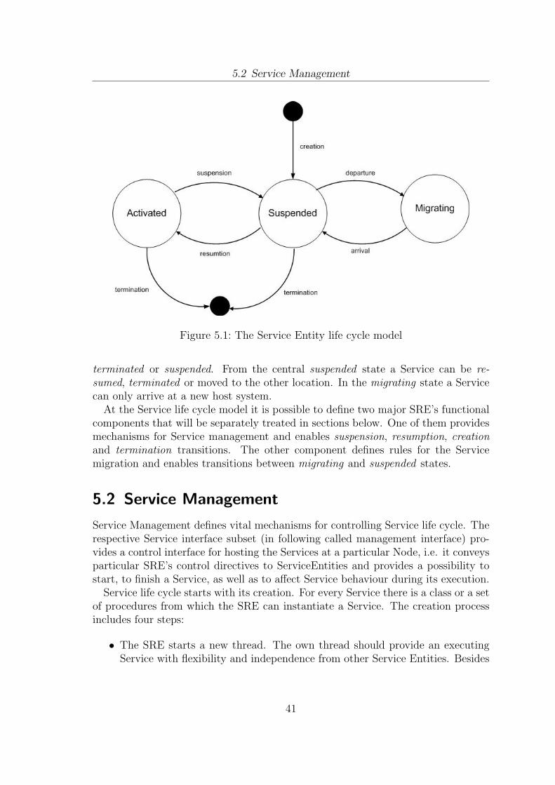
5.2 Service Management
Figure 5.1: The Service Entity life cycle model
terminated or suspended. From the central suspended state a Service can be re-sumed, terminated or moved to the other location. In the migrating state a Servicecan only arrive at a new host system.
At the Service life cycle model it is possible to define two major SRE’s functionalcomponents that will be separately treated in sections below. One of them providesmechanisms for Service management and enables suspension, resumption, creationand termination transitions. The other component defines rules for the Servicemigration and enables transitions between migrating and suspended states.
5.2 Service Management
Service Management defines vital mechanisms for controlling Service life cycle. Therespective Service interface subset (in following called management interface) pro-vides a control interface for hosting the Services at a particular Node, i.e. it conveysparticular SRE’s control directives to ServiceEntities and provides a possibility tostart, to finish a Service, as well as to affect Service behaviour during its execution.
Service life cycle starts with its creation. For every Service there is a class or a setof procedures from which the SRE can instantiate a Service. The creation processincludes four steps:
• The SRE starts a new thread. The own thread should provide an executingService with flexibility and independence from other Service Entities. Besides
41
5.2 Service Management
this, Services running in parallel are easier to manage. That results in a betterfault-proneness property of the entire system2.
• The Service class is instantiated or in case of a procedural programming lan-guage the instantiation procedures are executed.
• The loaded Service is registered within the SRE by its unique name.
• The Service is initialized within its own thread. The initialization is a com-plex action and should be separately treated from the Service instantiation.The advantage of the separation is the potential possibility to schedule Ser-vice initialization. The scheduling routine can consider such parameters ascurrently available resources. Service initialisation requires a definition of theinitialization directive.
After a particular Service had been initialized, it is in the suspended state (figure5.1). The Service Entity is ready to be started. At the very beginning of theexecution the Service variables are assigned to default values. Nevertheless thisinternal Service state is a fully-fledged one and can be even immediately serializedfor e.g. transferring to the other network node. Hence, there is no difference whethera Service was executing and then has been hold on or is just newly initialized3.
To carry a Service over from the suspended into the activated state, managementinterface requires a definition of a start directive. By calling this directive a Servicebegins its activity and if required starts. The SRE admits more than one activatedService at the same time. The SRE should take care of that the Services do notperform contradictory actions. For example if one Service is asking for input fromthe user, some other Service should not be allowed to close the active interactionform and to show its own one.
The opposite directive to start which the SRE’s management component shouldcontain, is suspension. It returns the Service into suspended state. By calling thisdirective a Service stops performing any actions, closes or holds on its threads, closescommunication sessions.
The Service life cycle can be finished any time, when the Service is either in theactivatedor in the suspended state. For both cases service management defines atermination directive. By calling it, the Service frees up all the resources it hadallocated. The internal state of the Service is destroyed and cannot be restoredanymore.
2Of course threading always means a periodical switching of the execution context and thus anadditional overhead at the operation system level. On the other hand abandoning threadingutilization would just mean shifting this routing to the higher realisation level.
3A Service can be actually initialized with any internal state which is different from a defaultone. When it makes sense will be explained later in this section.
42
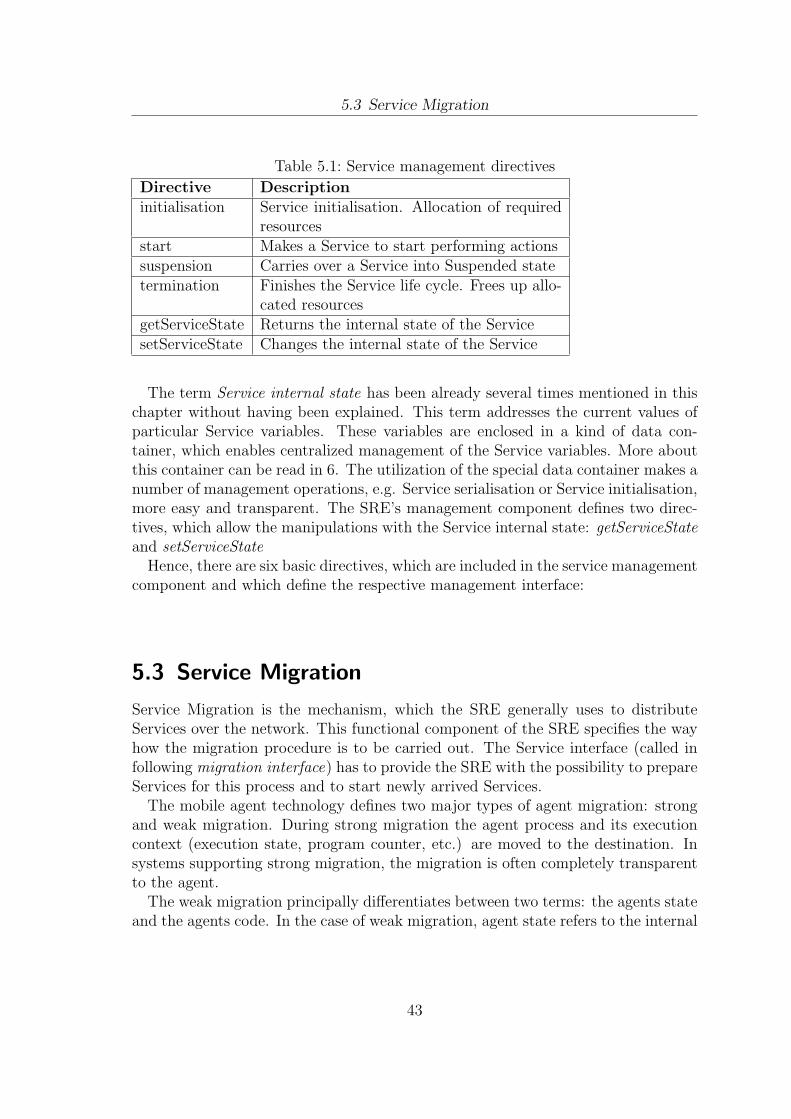
5.3 Service Migration
Table 5.1: Service management directives
Directive Descriptioninitialisation Service initialisation. Allocation of required
resourcesstart Makes a Service to start performing actionssuspension Carries over a Service into Suspended statetermination Finishes the Service life cycle. Frees up allo-
cated resourcesgetServiceState Returns the internal state of the ServicesetServiceState Changes the internal state of the Service
The term Service internal state has been already several times mentioned in thischapter without having been explained. This term addresses the current values ofparticular Service variables. These variables are enclosed in a kind of data con-tainer, which enables centralized management of the Service variables. More aboutthis container can be read in 6. The utilization of the special data container makes anumber of management operations, e.g. Service serialisation or Service initialisation,more easy and transparent. The SRE’s management component defines two direc-tives, which allow the manipulations with the Service internal state: getServiceStateand setServiceState
Hence, there are six basic directives, which are included in the service managementcomponent and which define the respective management interface:
5.3 Service Migration
Service Migration is the mechanism, which the SRE generally uses to distributeServices over the network. This functional component of the SRE specifies the wayhow the migration procedure is to be carried out. The Service interface (called infollowing migration interface) has to provide the SRE with the possibility to prepareServices for this process and to start newly arrived Services.
The mobile agent technology defines two major types of agent migration: strongand weak migration. During strong migration the agent process and its executioncontext (execution state, program counter, etc.) are moved to the destination. Insystems supporting strong migration, the migration is often completely transparentto the agent.
The weak migration principally differentiates between two terms: the agents stateand the agents code. In the case of weak migration, agent state refers to the internal
43
5.3 Service Migration
state and the private data of the agent. In weak migration, state and/or code canbe transferred. [36]
Discussing the general advantages and disadvantages of migration types is outsidethe scope of the current work. The important issue about strong migration is thatit requires on the hosts exactly the same operating system, machine architecturesand programming language. For extremely heterogeneous networks this approachdoes not suit. Hence a weak form of migration is the only adequate alternative forthe Services.
The most common case for the SRE is when a particular node wants to acquirea Service, which is situated on some other node in the network. In this simplesituation if the Service is running, it continues to run and does not notice themigration request at all. The SRE makes a copy of the source code and sends it tothe requesting node. Having arrived at the new location the Service is started in anormal way and is initialized with the default state.
The other case is when the SRE initiates the Service migration process by itsown. There can be various reasons such as limited computing resources or a lowbattery power. The migration component defines for this case a departure directive,which allows to inform a certain Service that it will be moved to a new destination.By calling this directive the Service prepares for the transfer. It’s state changes toSuspended. If the Service source code is already present at the destination node, it isnot transferred once again. Only the Service last state is moved. Having arrived atthe new host, the Service is started and is initialized with the appropriate internalstate. In contrast to a normal Service start, there may be some tasks that the Servicehas to execute on arrival, e.g. to inform other Service instances in the network aboutthe new location. To enable this, Migration component defines an arrival directive.
The case when the Service itself and not the SRE initiates the migration processis not assumed by the current concept of the SRE. However, if the future applicationscenarios require such Service behaviour, it will be possible only insignificantly tomodify the SRE. The main difficulty would be the maintenance of the unidirectionalnature of the management mechanisms, i.e. only the management entities can affectServices’ behaviour and not vice versa. An elegant solution is realized in Java Agletssystem [37]. Aglets interact with their host over AgletContext object. This is aspecial Aglet that can manipulate other aglets. Using AgletContext object Agletscan create new Aglets or even get some Aglet back, if it migrated to the other host.
A similar approach could be applied to the SRE. The SRE could host a specialService, e.g. MigrationService. If a particular Service is initialized and its descriptionindicates that this Service should be able to initiate migration itself, this Servicecould get a reference to the MigrationService. If the mobile Service desires to leavethe host, it informs MigrationService, which interacts periodically with the SRE overan extended Service interface. After that the common service migration processis started, and the SRE prepares the common migration routine by calling thedeparture directive.
44
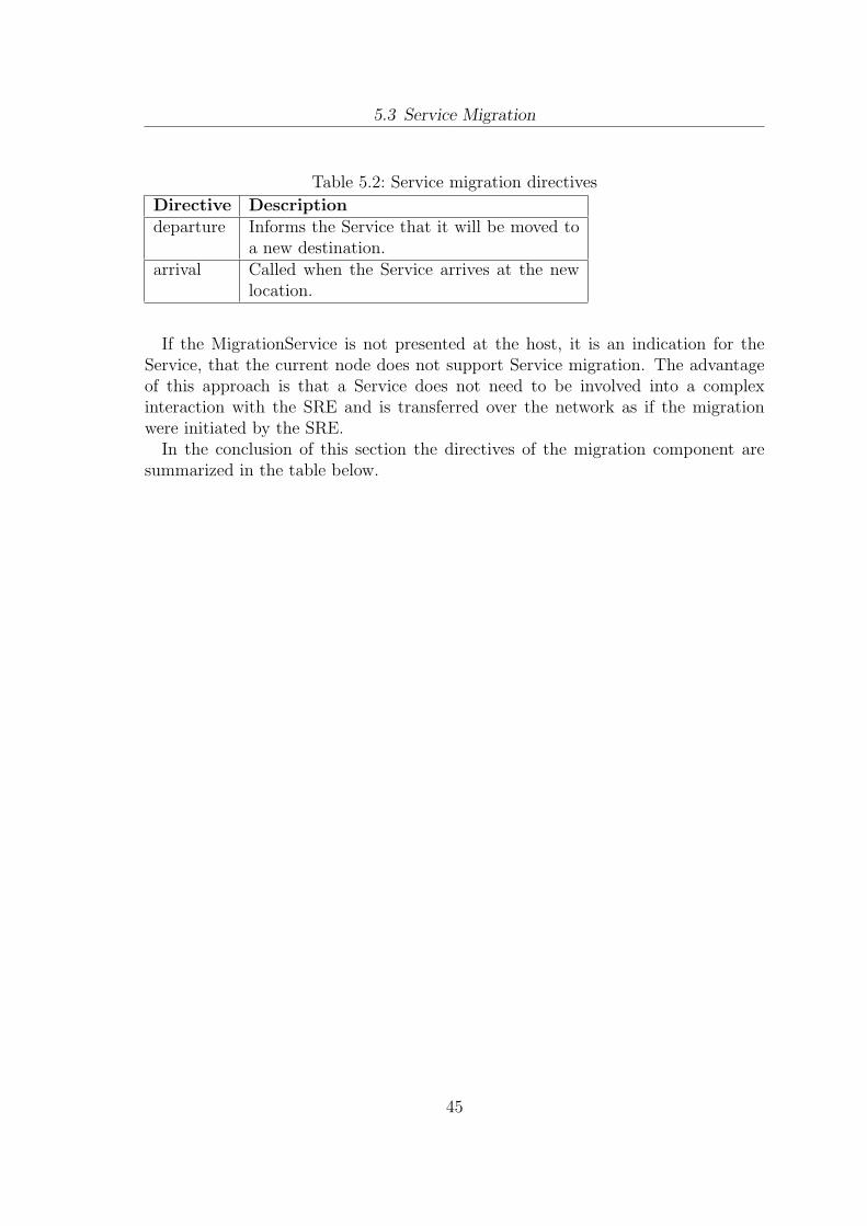
5.3 Service Migration
Table 5.2: Service migration directives
Directive Descriptiondeparture Informs the Service that it will be moved to
a new destination.arrival Called when the Service arrives at the new
location.
If the MigrationService is not presented at the host, it is an indication for theService, that the current node does not support Service migration. The advantageof this approach is that a Service does not need to be involved into a complexinteraction with the SRE and is transferred over the network as if the migrationwere initiated by the SRE.
In the conclusion of this section the directives of the migration component aresummarized in the table below.
45
6 Service Entity
After the introduction of the key functional components of the service runtime envi-ronment (SRE), a suitable concept for Services is to be conceived. The SRE togetherand the derived Service interface pose indirectly a number of constraints to the un-derlying architecture of the Service Entity. SRE’s directives assume a particularService behaviour and prescribe a realisation of certain capabilities.
Basically, there are two major classes of Services that the SRE aims to support:composed Services and non-composed Services. A non-composed Service can beseen as a full-fledged application entity, which is executed at a single node. Theexamples of non-composed Services are a text editor, instant messaging programslike ICQ, network games like chess or cards.
Unlike non-composed Services, composed Services make use of other Services thatare present in the current network. In extreme cases such a Service can even possessno own application logic, but completely rely on the Services it can find at theneighbour nodes. Similar approaches exist in the Web Services research (web servicescomposition) [38]. The utilization of a composed Service is completely transparentfor the end-user. The user is not aware of the number of Services the composedService consists of. The Service usage differs insignificantly from the usage of anon-composed Service. As an example consider a simple distributed Service, whichworks like a walkie-talkie. The conversation between two users is based on sendingand receiving of little audio files. Assuming there is a speech recognition servicesomewhere in the network. The walkie-talkie Service can be dynamically extendedby the speech recognition feature, so that afterwards each user has a history of aconversation as a text file. From the user perspective the initial walkie-talkie Servicediffers from the composed Service only by the absence of the additional option ”saveas text” in the settings of the Service.
Independently of the composition characteristics all Services can be divided intothose, which work without interaction with their users and those, which invoke userinteraction. The later group of services should implement appropriate mechanisms,e.g. Graphical User Interface, Audio User Interface etc. which enable user inputand application output.
An important Service capability is to interact not only with the user, but alsowith other Services. This enables development of a wide range of application basedon peer-to-peer communication.
In order to be able to distinguish between numerous Services, every Service musthave a unique description. The description provides details on what kind of Service it
46
6.1 Service Description
is (composed, non-composed), how it is to use, who is the author, security details etc.It may also contain special information enabling construction of Service taxonomiesin the current dynamic network or even provide ontology description in order tomake possible personalized, context dependent Service usage.
Service state is also an important component of every Service entity.In following the enumerated components a Service Entity is made up of will be
discussed in sections below.
6.1 Service Description
Service description is an essential component of every Service Entity. The need todescribe a Service is analogous with the requirement for labelling goods or products.Product labels provide a summary description of the good to which it is attached.This information is used to make a rational decision of purchasing and utilizing theproduct.
The description of Services requires a high grade of accuracy. It is not enoughjust to reflect functional properties of the Services, but it is also needed to describethe complexity of the non-functional characteristics. A Service is not a function.It is a function performed on behalf at a cost. The cost is not always some mone-tary price; it is a whole collection of limitations. The non-functional properties ofServices include temporal and spatial availability, charging styles, settlement mod-els, settlement contracts, Service quality, security, trust and ownership. That is whysuch trend approaches as Universal Description, Discovery and Integration (UDDI),the Web Services Description Language (WSDL) and the Web Services Flow Lan-guage (WSFL) do not cover the entire scope. They lack the accuracy required tocompose Services dynamically1 [39]. Dynamic Service composition involves dynamicService search and dynamic composition phases. However, most of existing Servicedescription methods focus only on search or composition individually[40]. Generallyspeaking, novel Service description models are in demand, which would allow thedescription of functional and non-functional properties, dynamic Service search andcomposition.
Service description is a large topic and is deserving of a separate research work.That is why only core considerations and principles are discussed in following in orderto enlighten the nature of the Service description component. Since the definitoin ofa format for the Service description is not a goal of the current research, the draft,which is proposed in this document, is based on principles, which would allow toextend and to complete it any time. The guideline for the draft development is theService definition in section 2.1.
The set of Service properties to be outlined in the Service description is reasonableto divide into two major subsets, static and dynamic properties. Static properties
1Dynamic Service composition is one of the desired features for the SRE
47
6.1 Service Description
are once set and do not need to be ever changed. The examples of static detailsare Service name, manufacturer which released the Service, date of release, versionnumber, contact information, some static data, which enables secure usage of theparticular Service etc. These read-only properties can be useful for human as wellas for automated processes.
The dynamic part of the Service description can be seen as a kind of a whiteboard.The content can be put in either by a Service itself or by the SRE. The examples ofdynamic data are
• Service classification. Distributed Service taxonomy simplifies the process ofService discovery and Service delivery. The place that a particular Service hasin a taxonomy tree can vary from network to network. That is why this datahas to be changed dynamically. An interesting approach is introduced in [41].This paper introduces distributed UDDI protocol which is adapted to mobilead hoc networks.
• Service ranking. The nodes in a mobile network can host Services, whichserve a similar goal. However these Services may differ in resource consume,efficiency, functionalities etc. The righteous question is what Service to take?An adequate Service ranking system could be an answer. An example ofa ranking system for MANETs is introduced in [42]. This approach usesa selective benchmark strategy analyzing context, Service level and resource-related information to make fast decisions for Service selection and contingencyreaction.
Static Service Description
One of the main goals of the Service description is to reflect the uniqueness of aparticular Service Entity. The ability to distinguish between two objects is the basicprinciple, which enables the realization of almost all operations on Services. All therelated projects, which were introduced in chapter 4 prescribe specific propertiesenabling clear object identification. The so called ID (AgletID, AgentID, ServiceIDand other derived terms) can be a unique string, a large number or it can consist ofseveral attributes such as the name of the Service provider, Service version numberetc. The ID parameter for Services is called ServiceID and represents just a uniquestring.
IDs are frequently unhandy for a human and are used by the software internalprocesses like Service communication, Service search, Service exchange etc. For thehuman usage it is reasonable to define an alternative informative name. ServiceName property is not required to have a unique value. For the case, when there areseveral Services in the network with the same name, the Service description containsAbout property providing the user with additional information in a friendly format.
48
6.1 Service Description
The other Service properties, which may be of interest for the user are Vendor Nameand Address, Contact Phone and E-mail, Service Version and Date of Release.
While the enumerated properties describe Service exterior characteristics, the nextblock of properties enlightens the Service from the technical perspective. As it waspreviously mentioned there are two kinds of Services: simple and composed ones.ServiceType property of a particular Service Entity indicates its type.
In case of a composition the current description draft proposes a simple way toreflect this fact. PartialServiceIDs point in the description to the components aparticular Service is made up of. When a composed Service Entity is initializedby the SRE, the task of the execution environment is to discover the compositionelements in the network and to provide the instantiated object with references tothem. This approach assumes that PartialServiceIDs are a priori set in the Servicedescription. Furthermore it is assumed in following that every composed Service in-cludes the complete knowledge about the Sub-Services and implements logic for theircomposition. The ideal scenario is, however, when the Services could get togetherabsolutely dynamically, i.e. PartialServiceID are found out and the compositionlogic is generated by the SRE automatically. Dynamic Service composition wouldrequire at this point from the Service description a complex representation ofServicecapability, including semantic and syntactic details for the Service utilization. Thisis a great challenge, which due to the complexity of the problem scope cannot betreated within this work.
The next important issue, which should be treated within the Service description,is the definition of the connection type a particular Service involves. The SRE hasa potential to support at least two kinds of Services: real-time and non-real time.The type of required connection channels should be dealt as the ConnectionTypeparameter in the Service description, so that the SRE can give to an initializing Ser-vice Entity the references to the appropriate communication channels. The currentDescription draft proposes two parameter values: RealTime and NotRealTime.
Resource management is another aspect, which should be reflected within theService description. There are system resources which require a particular accu-racy utilizing them. These are resources which are present on systems as the onlyobject, e.g. video stream from the photo camera, keyboard etc. In order to avoidconflicts while utilizing them, it is required to declare these resources in the Servicedescription. The SRE could manage then the usage of these critical resources.
An important issue about exclusive resources is the way how they are addressed.Resource declaration has to be uniform for all the systems independently from thereal names of the resource objects. The same requirement concerns the way howthese resources are utilized. Hence, for every exclusive resource there must be a wellknown name and a uniform interface, which enables the utilization of this resourceby every Service Entity at every SRE. For example, every Media Player object shouldbe referenced as AudioOutputDevice, hardware microphone as AudioInputDevice,web browser (IE, Firefox, Opera etc.) as HtmlOutputDevice etc. The list with the
49
6.2 Service State
name mappings has to be managed by SRE.
Dynamic Service Description
Service properties, which may change either during Service execution or as a result ofa Service migration between networking nodes, are to be declared as dynamic data inthe description section. For example protection mechanisms of the SRE can use thissection to save digital signatures, to share the public key, to include some encrypteddata and so on. Besides this, the dynamic description may contain some statisticsdata, which changes each time a Service Entity migrates to the other host. Servicepopularity, Service classification, Service discovery and other important operationson Service Entities may make use of the Service Description. Finally, Service Statecan be also included into Service Description
6.2 Service State
The state of a Service is defined as a subset of Service variables, their values andprivate data of the Service. In every execution step the Service variables can getnew values or the private data can be modified. This leads to the change of theService state.
There are several reasons for treating only the subset and not all the variablesand private data. Consider the example of a simple messenger Service. There isa list of user contacts. Furthermore there is a list of only those contacts whichare currently online. Each conversation session is saved in a history file. Now theinstance of the messenger Service has to be moved to the other node in the network.GetServiceState directive is called by the SRE is transferred to the new locationtogether with its state. It is obviously that the new node has different neighboursthan the previous one. Thus the list of online contacts can get invalid at the newlocation and the contacts discovery process should be started on arrival in any case.So it makes no sense to transfer the list of online contacts over the network. Incontrast the permanent contact list and the conversation history can be useful atany node in the network.
Hence, the example above shows that only a certain subset of Service variablesand Service private data is of interest for the such operations on Service state asService migration. The definition of this subset is the task of particular Servicedevelopers.
Another important issue is the management of the Service state. In order toprovide structural clearance and enable easy way to manipulate Service state, it isreasonably to treat the state in a special data structure. This data structure shouldstay as simple as possible and serve as a pool for important Service values.
50
6.3 Service Communication
The realisation for the similar concept is SUN’s JavaBeans for the Java 2 Plat-form, Standard Edition (J2SE). JavaBeans are in fact ordinary Java classes whichhold constraints of the SUN’s JavaBeans API Specification. They have to obey cer-tain rules for method naming, construction, and behaviour. Due to flexible designJavaBeans are widely used and applied as containers for data transfer and representreusable components for construction of larger software architectures.
Avoiding implementation details in the current section, one should mphasize thatthe Service state can be realised as an object which contains all the important data.This object can be requested by Service Framework any time. Furthermore, Servicestate object should contain methods that enable reading out every single value.That is the way how Service Framework accesses Service data for e.g. its furtherserializing and preparing for migration to the new location. Besides mechanisms forreading out, the Service state object should implement methods for changing thestate data. These methods are used by the Service Entity to modify its state.
6.3 Service Communication
Service Communication is an important capability of Service Entities, enabling in-teraction of Services with each other, even if they are situated on different nodesor are accessible only through the Internet. According to the design of ACSF, theframework which will be used to test the capabilities of the SRE, Services have adirect access to the Network layer of the ACSF architecture. The Network layer isresponsible for opening and maintaining a communication channel. It includes logicfor apportioning of network resources between few Service Entities communicatingat the same time. The Network layer hides from application logic of a particularService any details regarding utilization of wireless technology (Bluetooth, IEEE802.11 etc.), connection and reconnection details and all the other networking spe-cific procedures.
The Network layer is accessible for the Services through the Network Interface.Every time when a communication based Service is initialized, it gets a reference toan object implementing this interface. Thus a Service acquires an ability to accessother Services in the network, to use Internet resources etc. The specification ofNetwork layer’s capabilities and the Network Interface is beyond the scope of thecurrent thesis. The goal of this section is to define an extension to the Serviceinterface, which enables Network layer to contact a particular Service Entity, todeliver internal control directives and messages from other Nodes.
As it was previously mentioned in chapter 1, REST principles lie at the base ofthe ACSF communication architecture. REST is the abbreviation for Representa-tional State Transfer. This term and the architectural principles were introducedin the dissertation of Roy Fielding [43]. The central conceptual point in REST isresources which can be referred using URI. REST defines a collection of network
51
6.3 Service Communication
architecture principles which outline how resources are defined and addressed. Thusit is prescribed, that the communication is client-server oriented and communicationstate is not saved at the nodes. Using REST principles for ACSF is beneficial inmany aspects. Easy syntax and semantics make Service development and Serviceexecution simpler than the usage of RPC, RMI or other technologies for distributedapplications. The only issue, which is to be considered - the Service communicationshould be reduced to a set of operations on resources according to a principle calledCRUD: create, read, update, delete.
Hence, Service interface should define four methods, which can be called by ACSFNetwork layer in order to forward the request to the communicating Service Entity.The call of these directives may be parameterized by additional arguments likeresource id, resource name, resource description etc. These parameters are thenincluded in the resource URI. As a response a requesting node can receive variousresponse codes, that indicate whether the operation could be successfully executed orthere were any errors. The main communicational methods which Service interfaceshould prescribe to Services are:
• CreateResource. The call of this directive creates as a rule a new object onthe Node. In some cases it may enforce the coping of an already existingobject. The possible request responses are success, access denied, operation isnot possible (if for example there is not enough memory), wrong URI format.
• ReadResource This directive requests a resource. The resource can be an objectlike picture, xml file etc. or a result of some calculation. As a response theasking node can get the resource itself or one of the response codes: accessdenied, operation is not possible (for example because of an object size), wrongURI format, modified (and date of modification), resource is missing.
• UpdateResource. This directive modifies an existing resource. In some rarecases the call of this directive may initiate the execution of some computingroutine which changes the state of the asked node. In order to enable synchro-nisation of operations on an object this directive may set or release a lock, sothat other Service Entities cannot temporary use current object. The possibleresponses are success, access denied, operation is not possible (if for examplethe object is locked by some processes), wrong URI format, resource is missing.
• DeleteResource. The directive is called when some resource should be de-stroyed/released. That does not always mean that some object is perma-nently deleted. It may be just temporary disabled and used again duringfuture Service execution. The same consideration is met if the resource issome computational operation. It may be just hold on and continued againlater. DeleteResource may response with following codes: success, access de-nied, operation is not possible, wrong URI format, resource is missing.
52
6.3 Service Communication
Communication based on these principles, as well as communication in mobilead hoc networks in general is a great challenge from the perspective of securityprovision. The discussion of the approaches and the realisation of the particularsecurity mechanisms for ACSF and for the SRE are beyond the scope of the currentwork. However, it is important briefly to introduce the main potential threats, inorder to be aware of the existing problems and to provide from the very beginningthe possibility of the appropriate security mechanisms integration in the systemarchitecture. To secure an ad hoc network, the following attributes are considered:availability, confidentiality, integrity, authentication, and non-repudiation. Theseattributes are detailed explained in [44]:
• Availability. Availability ensures the survivability of network services despitedenial of service attacks. A denial of service attack could be launched at anylayer of an ad hoc network. On the physical and media access control lay-ers, an adversary could employ jamming to interfere with communication onphysical channels. On the network layer, an adversary could disrupt the rout-ing protocol and disconnect the network. On the higher layers, an adversarycould bring down high-level services. One such target is the key managementservice, an essential service for any security framework.
• Confidentiality. Confidentiality ensures that certain information is never dis-closed to unauthorized entities. Network transmission of sensitive information,such as passwords, banking PINs, requires confidentiality. Leakage of such in-formation to unauthorized individuals could have bad consequences.
• Integrity. Integrity guarantees that a message being transferred is never cor-rupted. A message could be corrupted because of benign failures, such as radiopropagation impairment, or because of malicious attacks on the network.
• Authentication. Authentication enables a node to ensure the identity of thepeer node it is communicating with. Without authentication, an adversarycould masquerade a node, thus gaining unauthorized access to resource andsensitive information and interfering with the operation of other nodes.
• Non-repudiation. Non-repudiation ensures that the origin of a message cannotdeny having sent the message. Non-repudiation is useful for detection andisolation of compromised nodes. When a node A receives an erroneous messagefrom a node B, non-repudiation allows A to accuse B using this message andto convince other nodes that B is compromised.
In order to achieve these security goals, the SRE has to be extended by mecha-nisms providing the desired secure communication. Additionally Service Description
53
6.3 Service Communication
can be used for describing the important security details, like public key, certificate,digital signatures etc.2
Another important view on Service communication is the Quality of Service(QoS)3. The United Nations Consultative Committee for International Telephonyand Telegraphy (CCITT) Recommendation E.800, has defined QoS as: ”The col-lective effect of service performance which determines the degree of satisfaction of auser of the service”. In dependence on particular application, the QoS constraintscan be: the available bandwidth, end-to-end delay, delay variation (jitter), probabil-ity of packet loss, and so on. This kind of demand puts more pressure on the networkand the routing protocols which are used to support the communications[45].
In mobile ad hoc network, node mobility often results in frequent topologychanges, which represents a significant challenge when designing QoS routingprotocols. High node mobility can make QoS requirements unaccomplishable.Consequently, it is required, that the network stays combinatorically stable in orderto achieve QoS support. This means that the changes in network topology mustbe slow enough within a particular time window to allow the topology updates topropagate successfully as required in the network [46].
QoS in ACSF and SRE in particular is motivated by aiming to support real timeServices as well as Services based on non-real time communication principles. Thecurrent concept and the current implementation of ACSF do not differentiate yetbetween QoS classes. Certain extensions are needed not only at the ACSF Networklayer to realize the desirable functionality, but also outside ACSF architecture atthe lower levels of the Network protocol stack. As for the SRE there exists already apotential possibility for support of QoS. The Service Description that is available viatextitGetServiceDescription directive of the Management interface could contain theindicator for connection types, which a particular Service needs for communicationpurposes. Depending on this description, ACSF Network Interface can provide theService with appropriate facilities for data transfer.
The introduced extension of the Service interface is summarized in the table below.
2Service Description is detailed discussed in section 6.13Here: the terms Service as definded in 2.1 and Service in context of QoS differ in semantics
54
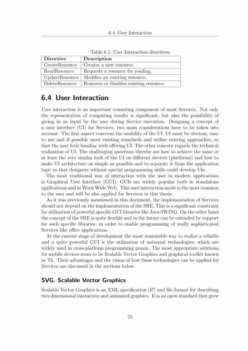
6.4 User Interaction
Table 6.1: User Interaction directives
Directive DescriptionCreateResource Creates a new resource.ReadResource Requests a resource for reading.UpdateResource Modifies an existing resource.DeleteResource Removes or disables existing resource.
6.4 User Interaction
User interaction is an important consisting component of most Services. Not onlythe representation of computing results is significant, but also the possibility ofgiving in an input by the user during Service execution. Designing a concept ofa user interface (UI) for Services, two main considerations have to be taken intoaccount. The first aspect concerns the usability of the UI. UI must be obvious, easyto use and if possible meet existing standards and utilize existing approaches, sothat the user feels familiar with offering UI. The other concern regards the technicalrealization of UI. The challenging questions thereby are how to achieve the same orat least the very similar look of the UI on different devices (platforms) and how tomake UI architecture as simple as possible and to separate it from the applicationlogic so that designers without special programming skills could develop UIs.
The most traditional way of interaction with the user in modern applicationsis Graphical User Interface (GUI). GUIs are widely popular both in standaloneapplications and in Word Wide Web. This user interaction mode is the most commonto the user and will be also applied for Services in this thesis.
As it was previously mentioned in this document, the implementaiton of Servicesshould not depend on the implementation of the SRE. This is a significant constraintfor utilization of powerful specific GUI libraries like Java SWING. On the other handthe concept of the SRE is quite flexible and in the future can be extended by supportfor such specific libraries, in order to enable programming of really sophisticatedServices like office applications.
At the current stage of development the most reasonable way to realize a reliableand a quite powerful GUI is the utilization of universal technologies, which arewidely used in cross-platform programming praxis. The most appropriate solutionsfor mobile devices seem to be Scalable Vector Graphics and graphical toolkit knownas Tk. Their advantages and the vision of how these technologies can be applied forServices are discussed in the sections below.
SVG. Scalable Vector Graphics
Scalable Vector Graphics is an XML specification [47] and file format for describingtwo-dimensional interactive and animated graphics. It is an open standard that grew
55
6.4 User Interaction
out of an effort of the World Wide Web Consortium. The main idea motivating SVGwas to create a generic document-oriented solution for graphics that can be adaptedto modern media. The SVG specification is not just a format for fancy graphics. It’sa serious application designed by experts to match the most recent advancementsin 2D graphics and is almost as powerful as Java2D or GDI+ [48].
An important advantage of SGV is that all the graphic elements are describedas a text, which can be compressed. This is a significant consideration, becausesmall-sized files reduce the traffic and increase the communication productivity indynamic wireless networks.
Despite its name, SVG also supports raster images and text, and defines a genericway to include raster graphics in a document either as external or inline files. Fur-thermore W3C defines extensive dynamic capabilities of SVG. SVG drawings can beanimated by SMIL which is the recommendation of W3C or by a scripting languagelike ECMAScript or JavaScript.
SVG in combination with scripting facilities represents a platform-neutral anddevice-independent mechanism to define rich graphics based user interaction. Thevivid demonstration of this approach is SUN’s Lively project [49].
In addition to the SVG specification 1.1 W3C defines profiles for mobile devices.Because each mobile device has different characteristics in terms of CPU speed,memory size, and colour support, two profiles are defined. The first low-level profile,SVG Tiny (SVGT) is suitable for highly restricted mobile devices like cell phones;while the second profile, SVG (SVGB) is targeted for higher level mobile deviceslike PDAs [50]. Thus SVG technology suits for any potential participant of a mobilenetwork.
User interaction based on SVG technology will be realized in following way. Ser-vice Entities contain a front-end component which is responsible for generation ofcomplete or partial SVG documents. These documents can be accessed by the SREvia particular method calls which are a part of the Service interface. For interactionwith Services a user needs only a web browser, which is installed on most of themodern mobile devices.
SVG documents are displayed in the web browser and provide the user witha possibility to do an input. ECMAScripts serve as control mechanisms whichmake GUIs dynamic and do particular pre-processing tasks like evaluation of inputparameters. Every time when the user chooses a particular hyper link or submitssome data, the web browser makes a local request. This request is is forwarded tothe corresponding Service. The request is handled by the Service Entity. Afterwardsthe Service returns a new SVG document, which is displayed in the web browser.
In particular situations the response must not be obligatory a complete SVGdocuments. It’s enough to return a part of SVG document or just a parametervalue. This can be useful utilizing Ajax technology for retrieving the dynamic.For this purpose Service interface should define appropriate directives, which wouldsupport this approach.
56
6.4 User Interaction
Table 6.2: User Interaction directives
API directive DescriptionGetGui This directive prompts a Service to generate
a SVG or Tk GUI.GetGuiElement Used to get only a particular GUI element.
Tk. Cross-platform Widget Toolkit
Tk is a toolkit for programming graphical user interfaces. It was designed for theX window system used on UNIX systems, and it was ported to the Macintosh andWindows environments in Tk 4.1. Especially Tk runs on Windows CE platform,which is currently the most popular platform for handheld devices such as PDAs.
The basic operation entity in Tk is a widget. It is a window in a graphical userinterface that has a particular appearance and behaviour. The terms widget andwindow are often used interchangeably. Widget types include buttons, scrollbars,menus, and text windows. Tk also has a general-purpose drawing widget calleda canvas that can be used to create lighter-weight items such as lines, boxes, andbitmaps.
Tk widgets build up a hierarchy. There exists a primary window, which cancontain several children windows that in their turn may be also nested ones. Tkuses a naming scheme which helps to arrange windows on the display [51].
Due to its simplicity, Tk became a very popular cross-platform solution for realiza-tion of the Graphical User Interfaces. A number of widely used scripting languagessuch as Python, Perl, Lua etc. provide an interface for using Tk. This is an impor-tant issue, that lets designing a concept for Services without taking into account thepossible programming languages that the Services can be implemented in.
Those Services that might offer a Tk GUI as alternative to SVG GUI will followthe similar procedure. Calling a particular Service API directive for the very firsttime, the front-end component of a Service prepares a Tk window and displays it tothe user. All the further interaction is completely controlled by the Service Entity,which is responsible for showing and disabling GUI forms which are involved in theinteraction process. When the Service is stopped by the SRE, it has to finish all theforms, that have been started by this Service.
In the conclusion of this section the extension of the Service interface is summa-rized in the table below.
57
7 Proof Of Concept
This chapter enlightens the implementation activities of this thesis. The goal isto prove the concept of the service runtime environment (SRE). The achieved the-oretical considerations are to be converted now into a prototype implementation,demonstrating the possibility of the technical realisation. This process will requirethe discussion and the argued choice of particular implementation tools and tech-nologies. The developed prototype may reveal the need of some conceptual improve-ments, which will be summarized later in this document.
The implementation works comprise the realisation of functional components ofthe service runtime environment (SRE) as well as the realisation of an end-userservice. Section 111 outlines implementation steps of the SRE. Section 222 dealswith implementation details of the Service.
7.1 Implementation of the Service RuntimeEnvironment
The functional components of the service runtime environment (SRE) as introducedin chapter 5 are now to be implemented and integrated with ACSF.
ACSF is available as a Java implementation. That is why it is reasonable to chooseJava as a programming language for the SRE. At the current stage of developmentACSF defines a clear class structure, reflecting the architecture of ACSF as outlinedin section 2.5. Most of the basic functionalities are already implemented. However,some of them are still in development. The integration of the SRE as a new com-ponent requires an understanding of cooperation between existing components atthe technical level. The SRE has to meet prescribed conventional agreements andrely on available infrastructural mechanisms in order to be compatible with othercomponents.
The java package for the SRE has got the name de.fhg.fokus.ascf.sre and hasbeen integrated into the existing ACSF package structure. This package containstwo sub-packages, each one for a functional component of the SRE:
• de.fhg.fokus.ascf.sre.servicemanagement - comprises mechanisms for Servicemanagement
• de.fhg.fokus.ascf.sre.servicemigration - comprises mechanisms for Service mi-gration
58
7.1 Implementation of the Service Runtime Environment
Each of the packages contains two main elements: a service interface and a syn-chronous action message handler.
The Service interface prescribes a Service entity which methods it must implementto be compliant with a particular functional component of the SRE. The Service in-terfaces of the service management and service migration packages are implementedby an abstract element, the so called AbstractService. The AbstractService was al-ready predefined by ACSF and is the base of every Service. All Services extendAbstractService, thus acquiring basic functionalities like getter and setter for Ser-vice properties, inbound and outbound proxies for networking needs, access to thedescription fields etc. The former state of the ACSF development assumed thatServices were made up of Java classes compressed into jar-files, which could be de-ployed on-the-fly. However, the concept of Services as discussed in chapter 6 requiresServices to be independent from a particular implementation of the SRE. As it willbe shown in the next section Services can be realised in dynamic programming lan-guages, i.e. as a set of scripts. This will provide the desired independence fromthe underlying SRE implementation. How this issue is handled within SRE is alsodiscussed in section 7.2.
Synchronous action message handler is a kind of complementing element of aparticular functional component of the SRE. Its task is to handle synchronous net-working requests and to activate the respective computing routine of the SRE. Ac-tion message handlers are the obligatory elements required by Restac. Restac is thecommunication framework, also developed by Fraunhofer FOKUS, which is includedin ACSF and enables the REST based communication between nodes.
The actual logic of the SRE is implemented in the ServiceRuntimeEnvironmentclass. This class manages the list of Services. The control directives, which werediscussed in section 5, are realized as appropriate Java methods of this class. Al-ternatively, the ServiceRuntimeEnvironment class could be split and its logic couldbe distributed over two managing classes: ServiceManager and MigrationManager.The advantage of this approach would be a better structural clearness. However,it would require an unnecessary overhead for coordination and synchronization ofmanagers’ actions. That implies not only the longer response times, but also theadditional wastage of system resources. If the future system requirements insist onthis separation of roles, the restructure of the SRE will be a local task, which will notaffect the other ACSF components, which are placed outside the de.fhg.fokus.ascf.srepackage.
In following service management and service migration packages are discussed indetail.
7.1.1 Service Management
de.fhg.fokus.ascf.sre.servicemanagement package is made up of two classes:ServiceManagementInterface.java and ServiceManagementHTTPXSyn-
59
7.1 Implementation of the Service Runtime Environment
cActionMessageHandler.java.
ServiceManagementInterface
The ServiceManagementInterface interface prescribes a Service the implementationof four methods as outlined in section 5.2: initService(), startService(), suspendSer-vice(), terminateService() and getServiceState(). These methods except the last onereturn no value and are called at different stages of the Service life cycle.
getServiceState() returns a string, representing comma separated key-value pairs.The representation of the Service state as a string is necessary because of the specialmanner of the data exchange between Java classes and Service scripts. The utilisa-tion of Hashtables, Arrays and other data structures specific for Java would requirethe explicit import of the appropriate libraries within the body of a script. Thiswould make the Service scripts dependent on the SRE they are executed in.
ServiceManagementHTTPXSyncActionMessageHandler
The prime task of ServiceManagementHTTPXSyncActionMessageHandler is to han-dle web requests related to the Service management activities of the SRE. A specialHTTPX filter called UrlGroupFilter forwards the web requests referring particu-lar resources to the ServiceManagementHTTPXSyncActionMessageHandler. Thishandler extracts and verifies parameters and calls appropriate routines of the SRE.
The default response is the web page, which lists all the services accessible on thecurrent node and offers the possibilities to start, to suspend and to stop a particularService. In dependence on the chosen action SRE verifies, whether the respectiveaction can be executed. Afterwards the action is executed and the respective actionis performed on the Service. The scope of this master thesis does not comprise thedefinition of access policies or treatment of security issues. In the current imple-mentation every node can start, suspend or stop its own Service entities as well asService entities at any other node.
7.1.2 Service Migration
de.fhg.fokus.ascf.sre.servicemigration package is made up of two classes: ServiceM-igrationInterface.java and ServiceMigrationHTTPXSyncActionMessage-Handler.java.
ServiceMigrationInterface
The ServiceMigrationInterface requires the implementation of two methods: onDe-parture() and onArival(). As discussed in section 5.2 these methods are called whiletransferring a particular Service from one node to another. onDeparture() prepares a
60
7.2 Implementation of an End-user Service
Service for the migration process. onArrival() signalises a Service to execute certainactions after arrival at a new location.
ServiceMigrationHTTPXSyncActionMessageHandler
The prime task of the ServiceManagementHTTPXSyncActionMessageHandler is tohandle synchronous web requests related to the Service migration activities of theSRE. The default web interface allows initiating of a Service migration process forevery Service entity running on the current node. The obligatory request param-eter is the IP of the destination host. After submission SRE tries to transfer aparticular Service to the new destination via ServiceMigrationHTTPXSyncAction-MessageHandler. The same handler at the remote host can confirm transmissionor can decline it by sending BadRequest in dependence on the decision the remoteSRE meets.
The format of the messages, which could be exchanged between different SREs isnot discussed in the scope of this thesis. In later implementations the mechanismsof the SRE could be extended. Based on a set of particular rules and policiesSREs could exchange details regarding hosted services to agree on the conditionsfor service migration. Thus it could be possible to meet an agreement, whether theService code should be shipped with or without Service state as described in section5.3. In the current implementation a Service is transferred completely with its stateand its byte code.
The utilization of the SRE Service migration capabilities by user interactiondemonstrates only the basic principles. However, as explained in section 5.3 themigration process should be initiated in most cases not by the user, but automati-cally as a reaction of the SRE to the changes in the environment.
7.2 Implementation of an End-user Service
In order to demonstrate the capabilities of the service runtime environment (SRE)and to illustrate the concept of Services as outlined in chapter 6 an end-user Serviceis to be implemented. This Service will be in following called RootExtractor. It isa very simple application, which extracts a mathematical root of a maximal fourdigits number. A graphical user interface of the RootExtractor Service comprises aninput field for a number, a button for calculating and an output field for displayingthe result of the calculation. Although the application logic of the RootExtractorService is simple, it demonstrates all the important issues. Thus this Service can beinitialized, started, suspended, terminated and moved to any other device in the net-work. It is a stateful Service. Its state consists of the input variable. RootExtractoruses a graphical user interface and supports interaction with users.
The development of an end-user Service assumes a discussion of following issues:
61
7.2 Implementation of an End-user Service
choice of a programming language, integration of a cross-platform Service with theservice runtime environment (SRE), realisation of the service description and theservice state, realisation of the GUI, implementation of the application logic. Eachissue is separately discussed in a respective section below.
7.2.1 Programming Language for the Service Entity
The technical realisation scheme for the Services must be completely free from con-sidering the implementation details of the SRE (see chapter 6). In order to achievethe desired cross-platform property, Service application logic must be realised in aneutral programming language, which could be interpreted at any system. There isa large family of programming languages, fulfilling this requirement. The so calleddynamic languages bring an advantage of enabling programs that can change theircode and logical structures at runtime, add variable types, module names, classes,and functions during execution. These languages are frequently interpreted and gen-erally check typing at runtime. The popularity of dynamic languages is growing moreand more. Major companies such as Microsoft and Sun Microsystems are support-ing dynamic languages in their development platforms [52]. Due to the simplicity oftheir constructions dynamic language are easy to learn and are especially attractivefor even not well experienced programmers. The trend of the dynamic programminglanguages as the realisation means for the Services in the next generation networkswill surely held in the future. However, mobile networks may require the evolutionof modern dynamic languages regarding syntax and supported capabilities [53].
At the current moment the most popular dynamic languages are Python,JavaScript, Lua, Groovy, Perl, PHP, TCL, Ruby and some others. All of them havetheir advantages and shortcomings. Some of the languages are more convenient forcreating games, the other are better suited for making utilities or office applications.All of the enumerated languages can be embedded into static languages like Java,C#, C++ etc. That means, that the interpreters can be added to the classicprogram as an external library, which enables execution of the script commandswithin the running program. Thus there exists for example a Python interpreter asIronPython for .NET, as Jython for Java etc.
However, there are still unsolved problems of porting the embedded interpretersonto mobile devices. The integration of the interpreters into such runtime environ-ments as .NET Compact Framework or J2ME is at this stage not possible. Thecurrent realisations of interpreters are based on reflections, which are absent in thecompact versions of the virtual machines. There are commercial projects, initia-tives and open-source communities which are intensively occupied with these topics.However, currently offered solutions are neither ripe enough nor provide the satisfy-ing results. This is a serious limitation that has to be accepted during the realisationof the SRE.
As for the choice of a particular dynamic language for the RootExtractor Service,
62
7.2 Implementation of an End-user Service
this decision is not a fundamental one, because the interpreters can be easily ex-changed or added to the SRE. Europe’s ECMA International and the InternationalOrganization for Standardization has adopted in the ECMA-262 specification [54]a general-purpose cross-platform scripting language called ECMAScript. This lan-guage is widely used on the web, and is often referred to as JavaScript or JScript,after the two primary dialects of the specification. JavaScript support is alreadyincluded in jdk 1.6. This is a direct advantage, because Java language was chosenfor the realisation of the SRE. Besides this, ECMAScript is recommended by ECMAas a compliant language to SVG graphics format, which was previously discussed insection 6.4. These facts motivate the choice of JavaScript as an instrument for therealization of the RootExtractor Service.
7.2.2 Integration of the Service Entity into SRE
In order to provide the SRE with flexibility of adding new interpreters and to enablea better and more structural control over scripting commands there has been madea decision to implement a so called ServiceEntity wrapper. In the context of Java itmeans a realisation of a ServiceEntity-wrapper class, which encapsulates functionsfor reading the script, binding between scripting and java commands, managingthe Service state etc. This class has to implement interfaces, which enable Servicecontrol as discussed in chapters 5 and 6. The wrapper class is to be seen as adapter,which makes possible Service execution on every node. This class could be shippedtogether with Service scripts.
The advantage of this approach is that the SRE operates with Service-objectsimplemented in the same programming language. The SRE’s logic is isolated fromthe details of the interpretation routine. Thus there may be hosted several ServiceEntities, written in different dynamic languages and wrapped by different wrapper-objects. Due to the common interface the SRE can handle these Service entities inthe same way.
7.2.3 Service State and Service Description
The next technical issue is the realisation of the Service State and the Service De-scription. As it was previously explained in section 6.2 Service state as well asService Description have to stay cross platform, i.e. it must be possible to use themin any software environment.
The current development of ACSF defines already a cross-platform format ofdescription for ACSF Nodes. This format allows both saving of text and binary data.The description file is a sequence of key-value pairs with declaration of a value mimetype. The same format is acceptable for Services. However, the main shortcoming ofthe format is the absence of a clear hierarchy of the saved data. On the other hand, ifthe future application scenarios require the data hierarchy, the current format can be
63
7.2 Implementation of an End-user Service
easily extended. At the current stage a large advantage that definitely agues for theutilization of the existing format, is its simplicity, which implies the simple parsingand saving of computing resources on mobile devices. Besides this, the existence ofa uniform description format for nodes, Services and mediators contributes to theclearness and transparency of the entire system architecture.
From the technical perspective Service state represents a set of important vari-ables/Service properties which can be set during Service execution. In general thesekey-value pairs can be managed in the same data structure and in the same for-mat as Service description. Moreover, a combination of Service state and Servicedescription data in a common managing structure allows the reusing of the samemanaging mechanisms. Exactly this approach has been realised on praxis.
The common description/state file can be modified during the Service execu-tion. If the Service has to be moved to another node, this file is saved and addedto a Service Zip-archive, containing among others Service scripting files and theServiceScriptingWrapper-class. Afterward the package is transferred over the net-work.
7.2.4 User Interaction
de.fhg.fokus.ascf.sre.userinteraction package is made up of two classes: UserIn-teractionInterface.java and ServiceGuiHTTPXSyncActionMessageHan-dler.java.
UserInteractionInterface
The UserInteractionInterface defines two methods getGui() and getGuiElement()for supporting the interaction with the user. Both methods are parameterised by aresourcePath string. In dependence on a parameter value and on the GUI generationmode an appropriate GUI element is generated. The current implementation realisesonly the support for default GUI mode, that is SVG/HTML. The utilisation of TkGUIs is more specific for certain application scenarios. That is why the interactioncapabilities of ACSF are demonstrated only by means of SVG/HTM technology.
ServiceGuiHTTPXSyncActionMessageHandler
The ServiceGuiHTTPXSyncActionMessageHandler handles the incoming web re-quests. As it was discussed in section [6.3] Service entities should have a directaccess to the networking layer. The requests are forwarded by the networking layerdirectly to a particular Service. The ServiceGuiHTTPXSyncActionMessageHandleris actually to be seen as a complement element of the Service entity and not of theSRE. The reason why this handler was placed into the sub-package of the SRE is the
64

7.2 Implementation of an End-user Service
potential possibility to extend the handler by capabilities to monitor and to informthe SRE about the networking traffic generating by the Service entity.
7.2.5 Application Logic
The application logic of the RootExtractor-Service is realized as ECMA-scripts andconsists of two layers: backend layer and front-end layer. The backend layer com-prises scripts, which are interpreted within the SRE. The scripts of the front-endlayer are included in GUI, i.e. SVG pages which are displayed by a web browser.
The backend layer of the RootExtractor service consists of only one ECMAJavaScript. This script implements methods prescribed by the Service management,service migration and user interaction interfaces. It also includes methods realisingthe actual application logic of the Service, i.e. extraction of the mathematical root.
The front-end layer includes ECMA JavaScripts responsible for generating theGUI elements and supporting simple user interactions without involving the backendlayer. Thus these scripts prove whether a particular string in the input field is anumber and whether it consists of maximal four digits. Besides this, the front-endsscripts periodically synchronize the state of the GUI with the backend layer of theService.
65
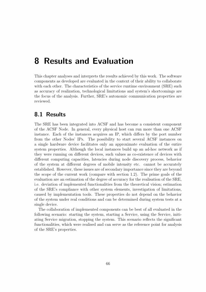
8 Results and Evaluation
This chapter analyses and interprets the results achieved by this work. The softwarecomponents as developed are evaluated in the context of their ability to collaboratewith each other. The characteristics of the service runtime environment (SRE) suchas accuracy of realization, technological limitations and system’s shortcomings arethe focus of the analysis. Further, SRE’s autonomic communication properties arereviewed.
8.1 Results
The SRE has been integrated into ACSF and has become a consistent componentof the ACSF Node. In general, every physical host can run more than one ACSFinstance. Each of the instances acquires an IP, which differs by the port numberfrom the other Nodes’ IPs. The possibility to start several ACSF instances ona single hardware device facilitates only an approximate evaluation of the entiresystem properties. Although the local instances build up an ad-hoc network as ifthey were running on different devices, such values as co-existence of devices withdifferent computing capacities, latencies during node discovery process, behaviorof the system at different degrees of mobile intensity etc. cannot be accuratelyestablished. However, these issues are of secondary importance since they are beyondthe scope of the current work (compare with section 1.2). The prime goals of theevaluation are an estimation of the degree of accuracy for the realisation of the SRE,i.e. deviation of implemented functionalities from the theoretical vision; estimationof the SRE’s compliance with other system elements, investigation of limitations,caused by implementation tools. These properties do not depend on the behaviorof the system under real conditions and can be determined during system tests at asingle device.
The collaboration of implemented components can be best of all evaluated in thefollowing scenario: starting the system, starting a Service, using the Service, initi-ating Service migration, stopping the system. This scenario reflects the significantfunctionalities, which were realised and can serve as the reference point for analysisof the SRE’s properties.
66
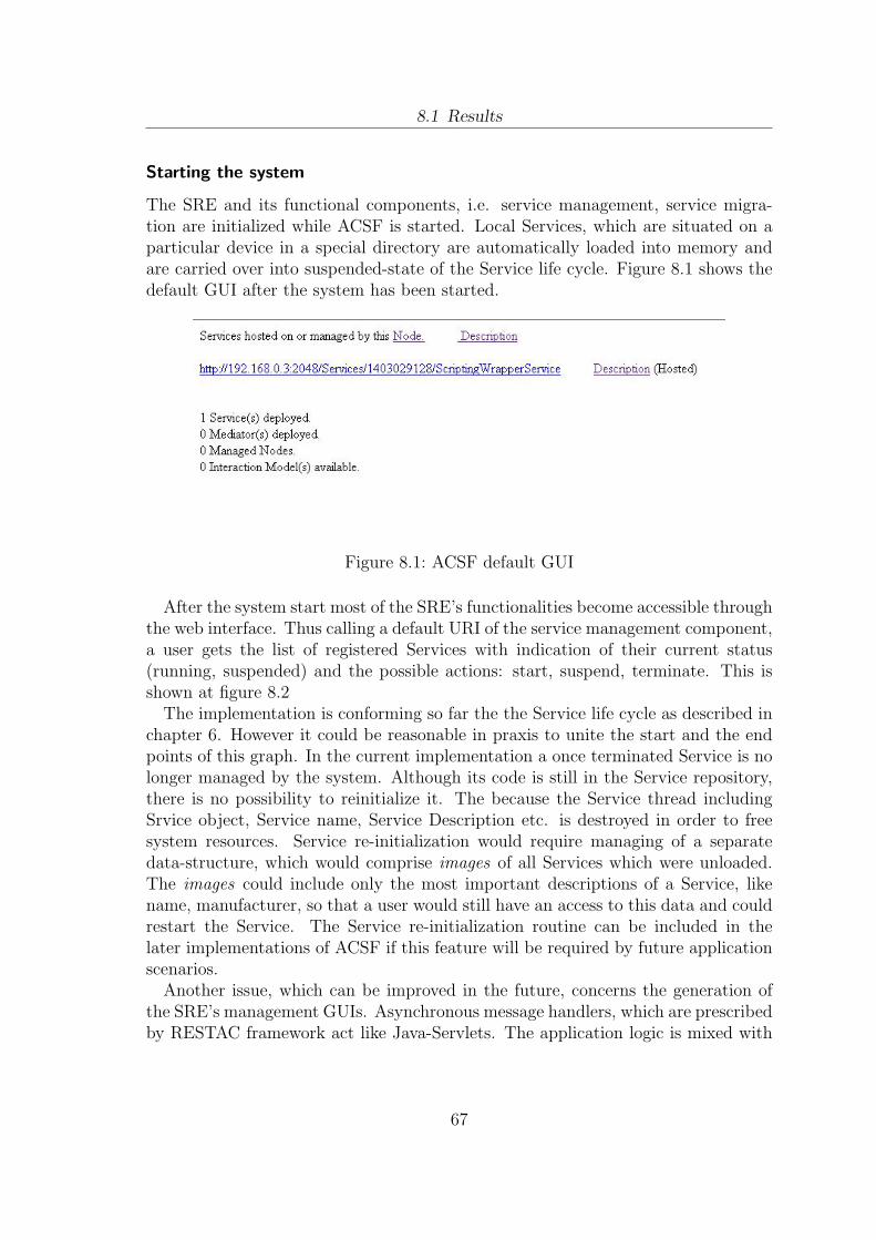
8.1 Results
Starting the system
The SRE and its functional components, i.e. service management, service migra-tion are initialized while ACSF is started. Local Services, which are situated on aparticular device in a special directory are automatically loaded into memory andare carried over into suspended-state of the Service life cycle. Figure 8.1 shows thedefault GUI after the system has been started.
Figure 8.1: ACSF default GUI
After the system start most of the SRE’s functionalities become accessible throughthe web interface. Thus calling a default URI of the service management component,a user gets the list of registered Services with indication of their current status(running, suspended) and the possible actions: start, suspend, terminate. This isshown at figure 8.2
The implementation is conforming so far the the Service life cycle as described inchapter 6. However it could be reasonable in praxis to unite the start and the endpoints of this graph. In the current implementation a once terminated Service is nolonger managed by the system. Although its code is still in the Service repository,there is no possibility to reinitialize it. The because the Service thread includingSrvice object, Service name, Service Description etc. is destroyed in order to freesystem resources. Service re-initialization would require managing of a separatedata-structure, which would comprise images of all Services which were unloaded.The images could include only the most important descriptions of a Service, likename, manufacturer, so that a user would still have an access to this data and couldrestart the Service. The Service re-initialization routine can be included in thelater implementations of ACSF if this feature will be required by future applicationscenarios.
Another issue, which can be improved in the future, concerns the generation ofthe SRE’s management GUIs. Asynchronous message handlers, which are prescribedby RESTAC framework act like Java-Servlets. The application logic is mixed with
67
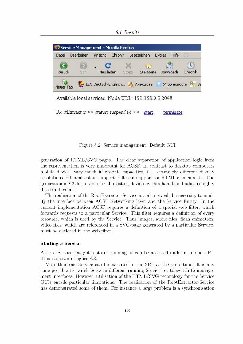
8.1 Results
Figure 8.2: Service management. Default GUI
generation of HTML/SVG pages. The clear separation of application logic fromthe representation is very important for ACSF. In contrast to desktop computersmobile devices vary much in graphic capacities, i.e. extremely different displayresolutions, different colour support, different support for HTML elements etc. Thegeneration of GUIs suitable for all existing devices within handlers’ bodies is highlydisadvantageous.
The realisation of the RootExtractor Service has also revealed a necessity to mod-ify the interface between ACSF Networking layer and the Service Entity. In thecurrent implementation ACSF requires a definition of a special web-filter, whichforwards requests to a particular Service. This filter requires a definition of everyresource, which is used by the Service. Thus images, audio files, flash animation,video files, which are referenced in a SVG-page generated by a particular Service,must be declared in the web-filter.
Starting a Service
After a Service has got a status running, it can be accessed under a unique URI.This is shown in figure 8.3.
More than one Service can be executed in the SRE at the same time. It is anytime possible to switch between different running Services or to switch to manage-ment interfaces. However, utilisation of the HTML/SVG technology for the ServiceGUIs entails particular limitations. The realisation of the RootExtractor-Servicehas demonstrated some of them. For instance a large problem is a synchronisation
68

8.1 Results
Figure 8.3: Service management. RootExtractor Service is started.
between front-end and backend layers of the Service entity. In order to make syn-chronisation transparent for the user, front-end scripts should periodically exchangedata with backend script.
Starting Service Migration
Service Migration GUI allows initiating a transfer of every initialized ServiceEntityto another Node. This GUI is shown in figure 8.4.
Figure 8.4: Service migration. Default GUI.
After arrival at a new location the Service gets the suspended status. The explicitstart request is expected from the user. This could be annoying for the user, whowould expect an automatic Service start. This usability aspect could be consideredin the later implementations of ACSF.
Figure 8.5: Service migration. Service was trasferred to the new location.
69
8.2 Evaluation
Stopping the system
The current state of ACSF development does not provide a possibility of correctsystem stop by the user. An appropriate interface will be required in the laterACSF implementations. However, already now SRE contains an event handler forsystem stop signal. In this case the loaded Services are terminated and their threadsare destroyed.
Conclusion
The review of the results shows that the service management and service migrationcomponents of the SRE have been realised according to the concept. Their collab-oration reflects the objectives of conducted investigation in chapter 5. Apart fromcertain suggestions and comments this part of the thesis has been successfully car-ried out. The next section evaluates the autonomic properties of the implementedSRE.
8.2 Evaluation
The previous section has enlightened the results of implementation. In the nextstep the autonomic properties of the SRE as well as of the respective Services areto be investigated. Firstly, it must be shown, that Services developed in accordancewith section 7.2 meet the requirements of section 3.3. Afterwards the functionalcomponents of the SRE are to be analysed in the context of requirements as definedin section 3.2.
8.2.1 Autonomic Properties of the Service Entity
The realisation schema for ACSF Services as introduced in section 7.2 characterises aService as an autonomous entity. Its application logic and internal processes cannotbe directly influenced by the SRE. Only the Service itself is aware of its internalactivities.
Self-configuration, self-optimisation and self-adaptation properties were not di-rectly demonstrated by the RootExtractor-Service. The simple application logicof this RootExtractor Service does not require any (re)configuration, optimisationor adaptation activities. However, the respective methods could be implementedwithin the Service script.
The Self-healing capabilities of the RootExtractor Service can be seen, while trans-ferring the Service from one Node to another. The RootExtractor finishes its activityon one ACSF node and then restores its state on another one. In general the self-healing property of Services depends on the self-healing characteristics of the SRE.If for example an ACSF node falls completely out, a particular SRE should assist
70
8.2 Evaluation
restoring the state of the Services. That means in particular, the SRE should pe-riodically make backups of the states of its Services. The states could be saved onhard drives or on other devices in the current network. Such mechanisms were notdiscussed and were not realised in the current thesis. This problem area is beyondthe scope of this work and requires a separate detailed investigation.
The self-protection property of Services as briefly introduced in section 6.3 is op-tional. The main protection mechanisms should be integrated into the SRE. How-ever, the application logic of a particular Service could implement some additionalprotection methods. For example some distributed Services could require a loginname and a password for utilising its functionalities. The application scenario ofthe RootExtractor Service does not require such mechanisms.
In contrast to the previous self- * properties, which the RootExtractor Servicedemonstrates, the self-implementation property cannot be evaluated in the currentimplementation of the SRE. This property is relevant for the composed Services. TheSRE requires service discovery mechanisms to support the composed Services. Thatmeans in particular that the SRE is not able to find Services a certain composedService is made up of. Consequently the SRE cannot provide a composed Servicewith the references to respective Services in the network. The conceptualisation andrealisation of the mechanisms supporting Service discovery were beyond the scopeof this work.
Hence, it has been shown, that non-composed Services developed as discussed insection 7.2 have all the required characteristics of autonomic entities. ComposedServices require the implementation of the Service discovery. Dynamic Service dis-covery is a necessary prerequisite for the realisation of the self-implementation prop-erty, enabling Service composition transparently for the end-user.
8.2.2 Autonomic Properties of the Service RuntimeEnvironment
The SRE is conceptualised in this work as a part of a distributed system. Theconcept assumes an active interaction between SREs on different network nodesbased on principles of autonomic communication (AC). Although the discussion ofthe global interactions between SREs was not the part of this thesis, it is to beshown in following, that the current implementation of the SRE does not entail atleast any limitations for fulfilling the requirements defined in section 3.2. Moreover,it is to be shown that the implemented functional components of the SRE couldcontribute to the adaptive behaviour of the network nodes. That means that theSRE in its current implementation could project the changes in the global contextto the context of the hosted Service.
In order to evaluate these two issues the implemented functional components ofthe SRE should be analysed in the context of requirements defined in section 3.2.
71
8.2 Evaluation
In following each list item describes how the fulfilling of a particular requirement issupported by the current implementation of the SRE.
• Self-awareness. A particular SRE manages a list of Services and has a directaccess to their descriptions. This is a prerequisite for realising mechanismsfacilitating the exchange of Service details between SREs. Exchanging suchinformation a particular SRE can be aware of the state of the neighbour net-work nodes.
• Self-configuration and Self-optimisation. The (re)configuration and optimisa-tion of a particular SRE involves the configuration and optimisation of runningServices. The functional components of the SRE can initiate these processeson Services by calling the setServiceState control directive.
• Self-healing. The self-healing mechanisms of the SRE could make use of thesetServiceState directive. In case of a system crash the SRE could use thismethod to set a particular Service to the state before system crash.
• Self-protection. The current implementation of the SRE does not handle pro-tection issues. That is why the mechanisms enabling a safe communication,service exchange and service execution can be integrated within the SRE as acompletely new component.
• Self-adaption. The functional components of the SRE provide a fundamentfor the realisation of the self-adaption property. Every Service can be started,hold on, terminated, reconfigured or moved to another Node. These actionscan be performed by the SRE in dependence on the global context.
Hence, the review of the functional components of the SRE in the context of therequirements in section 3.2 reveals that the SRE can be extended by the mechanismsenabling its autonomic properties in the global context. It was also shown, that theimplemented control mechanisms can contribute to the adaptive behaviour of theSRE as a part of the distributed system.
8.2.3 Conclusion
The evaluation of the results has confirmed, that the implemented functional compo-nents of the SRE as well as the implemented end-user Service fulfil the requirementsdefined in sections 3.2 and 3.3. That means, that the concepts of the SRE and re-spective Services as outlined in chapters 5 and 6 could be successfully realised. Theimplementation has revealed a number of technical issues, which should be improvedin later development. However, these constraints are not entailed by the conceptualshortcomings.
72
9 Conclusion
This chapter summarizes the current work, it emphasises the main results and pro-vides an outlook on possible future work. Section 9.1 provides an overview of thefindings and key achievements of the thesis and their contribution of knowledge.Further, it is critically assessed whether the results of this work meet the initialgoals as set out. Section 9.2 gives an outlook on possible future research activitiesand outlines the further development of the SRE.
9.1 Result Summary
This thesis has proposed an innovative concept of a service runtime environment fornext-generation networks. The review of literature revealed that the proposed SREand respective service concepts are a novel solution in the domain of service archi-tectures for dynamic wireless networks. The existing approaches assume services tobe intelligent and to implement complex methods for adaptivity and self-awareness.The SRE concept introduced in this thesis facilitates light-weight but at the sametime adaptive and self-aware services.
Based on a literature review and based on an analysis of the paradigm of auto-nomic communication the following conceptual requirements of the service runtimeenvironment have been identified:
• The SRE is foremost a container for services. It provides methods and mech-anisms for initializing, starting, suspending and terminating services.
• The SRE supports service migration. Weak migration is argued to be the mostsuitable migration form for the services hosted by the SRE. Service migrationcan be initiated either by user interaction or by the SRE.
• The SRE provides mechanisms for the interpretation of changes and eventswithin the network.
• The SRE can adapt its behaviour to evolving situations. In particular, SREcan enforce changes of the service execution context. This enables servicesto adapt their behaviour to the new context. As a result the SRE adapts itsbehaviour.
73
9.1 Result Summary
• The SRE can be implemented for various software and hardware environmentsthat comply with the requirements as stated in chapter 3.2, irrespective of theirparticular operating system and hardware configuration. .
Necessary characteristics of adaptive and self-aware services as assumed for theSRE can be summarized as follows:
• Services do not need to be aware of the state and the available resources ofthe mobile device or the network environment. These changes are monitoredby sensors and handled by the SRE.
• Services for the SRE are light-weight , they only contain the application logic.
• Services can be accessed by the SRE to control service behaviour using acommon interface.
• Services as handled by the SRE act fully autonomously. It is not possible forthe SRE to access internal processes of a particular service.
• Services can be transferred from one network node to another triggered by theSRE.
• Services are aware of the execution environment as provided by the SRE andgenerally allow the SRE adapting their behaviour.
• The implementation of Services does not depend on the actual implementationof the SRE.
The functional components of the SRE enabling service management and servicemigration were implemented as proof-of-concept. Since the ACSF framework is im-plemented in Java and the SRE had to be integrated, the SRE was also implementedin the Java programming language. The SRE as realised facilitates the following:
• Interpretation and execution of services written in ECMA JavaScript
• Dynamic integration of additional interpreters
• Initializing, starting, suspending and terminating services
• Exchanging services between networking nodes. Based on the user interactionthe SRE can terminate a particular service and transfer it to the other location.At the new location the service arrives with its state and its execution can becontinued.
An end-user service was implemented to demonstrate the capabilities of the SRE.This service is characterized by following properties:
74
9.2 Outlook
• The Service is realised as an ECMA JavaScript
• The service generates SVG-GUIs
• The service uses web-browser for display and user interaction
The interpretation and evaluation of the results as achieved confirmed that theproposed SRE concept is beneficial for the rapid development of sophisticated ser-vices. Although, not all theoretical considerations could be fully followed up, thiswork is considered to provide a meaningful contribution towards the developmentof a comprehensive and innovative service runtime environment for self-organisingdynamic networks.
9.2 Outlook
Since the successful implementation of the service runtime environment as detailedin this thesis is considered a meaningful contribution to service architectures forthe dynamic mobile networks in general, the current approach seems worth furtherdeveloping. The SRE will be further developed and extended within the ACSFproject. The next step in the further development could be the conceptualisationof the mechanisms enabling interpretation of changes within the mobile devicesor the network environment. In particular it assumes the definition of an APIfacilitating the monitoring of the environment. The appropriate rules and formatsfor data exchange between framework sensors observing the environment and theSRE where the data is interpreted, need to be refined. The methods and mechanismsfor interpretation should be flexible enough to cover predictable as well as non-predictable situations.
The other important task is a definition of suitable communication protocolsbetween the service runtime environments at different network nodes. The SREsshould be able to exchange details regarding hosted services to agree on the condi-tions for service migration and to provide secure service distribution.
As mentioned in section 6.3it is of vital importance to integrate the supportfor real-time services in the future. It will open new perspectives for the rapiddevelopment of sophisticated services based on video or audio streaming such as IPtelephony in the Internet. The utilisation and integration of QoS mechanisms isconsidered to be one of the highly desired features of the future SRE as part of theACSF.
The objectives of this thesis are of considerable interest to the author of this
75

9.2 Outlook
thesis. The achieved results give motivation to further occupy within this researcharea. The concept of light-weight and adaptive services in mobile environments, asintroduced in this work is expected to have a large potential in solving a numberof the remaining critical issues of self-organising dynamic networks. Initially, theresults of this work will be applied to the domain of culture and tourism, where light-weight services dynamically distributed in mesh networks can be used for indoornavigation and for providing visitors with multimedia content in museums.
76
Index
AC, 9ACSF, 10, 20Aglets, 29Autonomic Communication, 9autonomic communication, 18autonomic computing, 18Autonomous Communication Service
Framework, 10
environment, 15
MANET, 14Mesh networks, 15mesh networks, 14migration interface, 43mobile ad-hoc networks, 9
self-* properties, 17Service, 13, 46service, 11Service description, 47Service Entity, 13Service life cycle, 13, 39Service Migration, 43Service Runtime Environment, 13, 17service runtime environment, 10, 38Service state, 50SRE, 10, 13
User interaction, 55
WSN, 14
77

Attachment
Dieser Arbeit liegt eine CD-ROM bei, welche eine digitale Version der vorliegendenArbeit und den Quelltext der in der Arbeit umgesetzten Komponenten enthalt.
Kontaktinformation
Ilya GorodnyanskiyEmail: [email protected]: +49 1742151474Web: http://i-gorod.org
78
Bibliography
[1] Hassim Mohamed Yunos, Jerry Zeyu Gao, and Simon Shim. Wireless advertis-ings challenges and opportunities. Computer, 36(5):30–37, 2003.
[2] Oriana Riva, Tamer Nadeem, Cristian Borcea, and Liviu Iftode. Context-aware migratory services in ad hoc networks. IEEE Transactions on MobileComputing, 6(12):1313–1328, 2007.
[3] Kevin Curran, Maurice D. Mulvenna, Chris D. Nugent, and Alex Galis. Chal-lenges and research directions in autonomic communications. IJIPT, 2(1):3–17,2007.
[4] Ioannis Stavrakakis and Michael Smirnov, editors. Autonomic Communication,Second International IFIP Workshop, WAC 2005, Athens, Greece, October 2-5, 2005, Revised Selected Papers, volume 3854 of Lecture Notes in ComputerScience. Springer, 2006.
[5] Realman ’06: Proceedings of the 2nd international workshop on multi-hop adhoc networks: from theory to reality, 2006. General Chair-Marco Conti andProgram Chair-Jon Crowcroft and Program Chair-Andrea Passarella.
[6] Terranet. http://www.terranet.se/.
[7] Simon Dobson, Spyros Denazis, Antonio Fernandez, Dominique Gaıti, ErolGelenbe, Fabio Massacci, Paddy Nixon, Fabrice Saffre, Nikita Schmidt, andFranco Zambonelli. A survey of autonomic communications. ACM Trans.Auton. Adapt. Syst., 1(2):223–259, 2006.
[8] Jeffrey O. Kephart and David M. Chess. The vision of autonomic computing.Computer, 36(1):41–50, 2003.
[9] Francesco De Mola and Raffaele Quitadamo. An agent model for future auto-nomic communications. In WOA, 2006.
[10] Autonomic computing. the 8 elements. http://www.research.ibm.com/
autonomic/overview/elements.html.
[11] Laurent Lefevre. Heavy and lightweight dynamic network services : challengesand experiments for designing intelligent solutions in evolvable next generation
79
Bibliography
networks. In IEEE Society, editor, Workshop on Autonomic Communicationfor Evolvable Next Generation Networks - The 7th International Symposiumon Autonomous Decentralized Systems, pages 738–743, Chengdu, Jiuzhaigou,China, April 2005. ISBN : 0-7803-8963-8.
[12] Monique Calisti, Sven van der Meer, and John Strassner. Advanced AutonomicNetworking and Communication (Whitestein Series in Software Agent Tech-nologies and Autonomic Computing). Birkhauser Basel, 2008.
[13] V. Simon, L. Bacsardi, S. Szabo, and D. Miorandi. Bionets: a new vision ofopportunistic networks. proceedings of ieee wrecom. 2007.
[14] Sven van der Meer, William Donnelly, John Strassner, Brendan Jennings, andMıcheal O Foghlu. Emerging principles of autonomic network management.In IEEE Society, editor, Multicon Lecture Notes: in Proc. of 1st IEEE Inter-national Workshop on Modelling Autonomic Communications Environments,pages 29–48, Dublin, Ireland, October 25-26 2006. ISBN 3-930736-05-5.
[15] Arvind Gopalan, Sajid Saleem, Matthias Martin, and Daniel Andresen. Baglets:Adding hierarchical scheduling to aglets. In HPDC ’99: Proceedings of the 8thIEEE International Symposium on High Performance Distributed Computing,page 38, Washington, DC, USA, 1999. IEEE Computer Society.
[16] D. B. Lange and D. T. Chang. Programming mobile agents in java. Technicalreport, IBM, September 1997.
[17] Robert S. Gray. Agent tcl: A flexible and secure mobile-agent system. Technicalreport, 1998.
[18] Holger Peine and Torsten Stolpmann. The architecture of the ara platform formobile agents. In MA ’97: Proceedings of the First International Workshop onMobile Agents, pages 50–61, London, UK, 1997. Springer-Verlag.
[19] C. Baumer, M. Breugst, S. Choy, and T. Magedanz. Grasshopper: a universalagent platform based on omg masif and fipa standards, 2000.
[20] IKV++. Grasshopper mobile agent system. http://java.sun.com/products/servlet/index.jsp, 2003.
[21] N Migas, W. J. Buchanan, and K. McArtney. Migration of mobile agents inad-hoc, wireless networks. ecbs, 00:530, 2004.
[22] Nobuo Kawaguchi, Katsuhiko Toyama, and Yasuyoshi Inagaki. Magnet: ad hocnetwork system based on mobile agents. Computer Communications, 23(8):761–768, 2000.
80
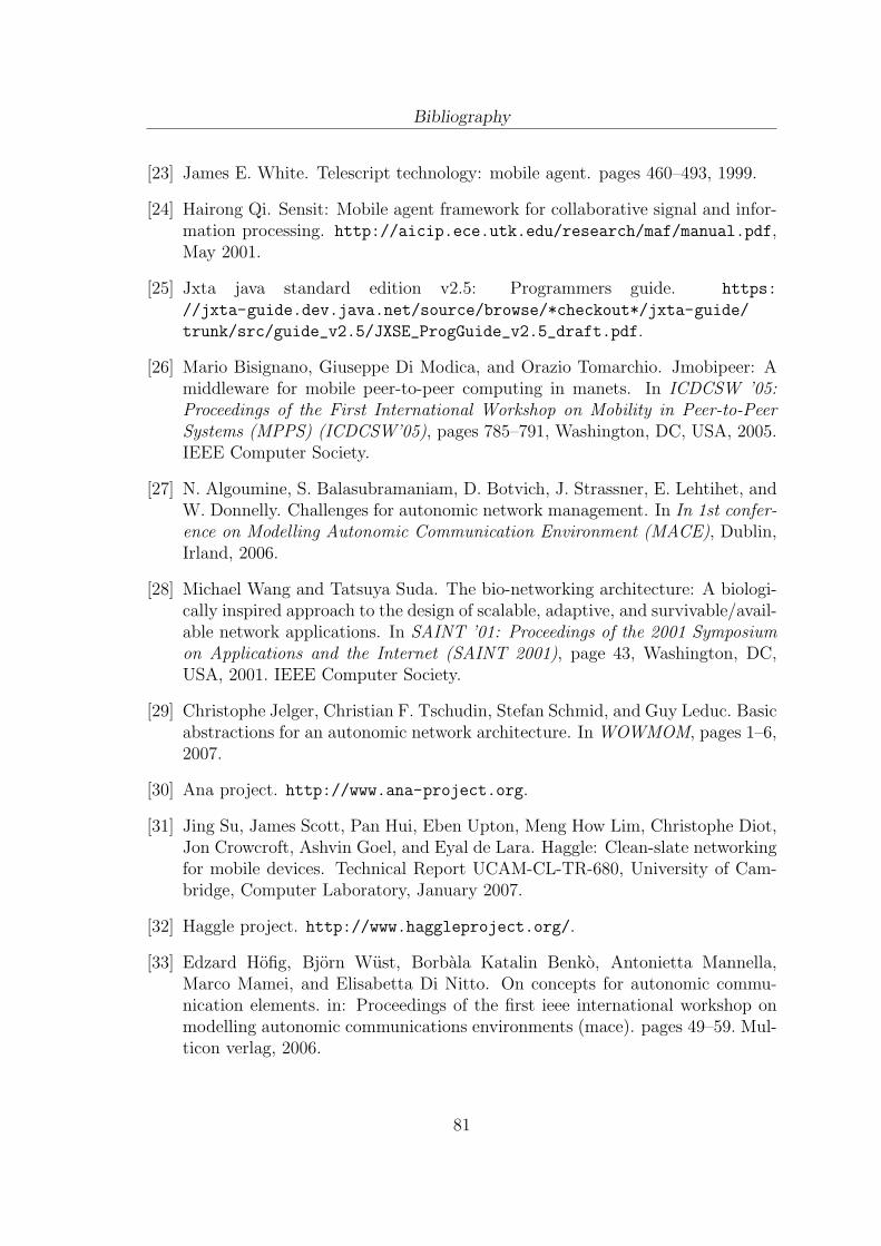
Bibliography
[23] James E. White. Telescript technology: mobile agent. pages 460–493, 1999.
[24] Hairong Qi. Sensit: Mobile agent framework for collaborative signal and infor-mation processing. http://aicip.ece.utk.edu/research/maf/manual.pdf,May 2001.
[25] Jxta java standard edition v2.5: Programmers guide. https:
//jxta-guide.dev.java.net/source/browse/*checkout*/jxta-guide/
trunk/src/guide_v2.5/JXSE_ProgGuide_v2.5_draft.pdf.
[26] Mario Bisignano, Giuseppe Di Modica, and Orazio Tomarchio. Jmobipeer: Amiddleware for mobile peer-to-peer computing in manets. In ICDCSW ’05:Proceedings of the First International Workshop on Mobility in Peer-to-PeerSystems (MPPS) (ICDCSW’05), pages 785–791, Washington, DC, USA, 2005.IEEE Computer Society.
[27] N. Algoumine, S. Balasubramaniam, D. Botvich, J. Strassner, E. Lehtihet, andW. Donnelly. Challenges for autonomic network management. In In 1st confer-ence on Modelling Autonomic Communication Environment (MACE), Dublin,Irland, 2006.
[28] Michael Wang and Tatsuya Suda. The bio-networking architecture: A biologi-cally inspired approach to the design of scalable, adaptive, and survivable/avail-able network applications. In SAINT ’01: Proceedings of the 2001 Symposiumon Applications and the Internet (SAINT 2001), page 43, Washington, DC,USA, 2001. IEEE Computer Society.
[29] Christophe Jelger, Christian F. Tschudin, Stefan Schmid, and Guy Leduc. Basicabstractions for an autonomic network architecture. In WOWMOM, pages 1–6,2007.
[30] Ana project. http://www.ana-project.org.
[31] Jing Su, James Scott, Pan Hui, Eben Upton, Meng How Lim, Christophe Diot,Jon Crowcroft, Ashvin Goel, and Eyal de Lara. Haggle: Clean-slate networkingfor mobile devices. Technical Report UCAM-CL-TR-680, University of Cam-bridge, Computer Laboratory, January 2007.
[32] Haggle project. http://www.haggleproject.org/.
[33] Edzard Hofig, Bjorn Wust, Borbala Katalin Benko, Antonietta Mannella,Marco Mamei, and Elisabetta Di Nitto. On concepts for autonomic commu-nication elements. in: Proceedings of the first ieee international workshop onmodelling autonomic communications environments (mace). pages 49–59. Mul-ticon verlag, 2006.
81
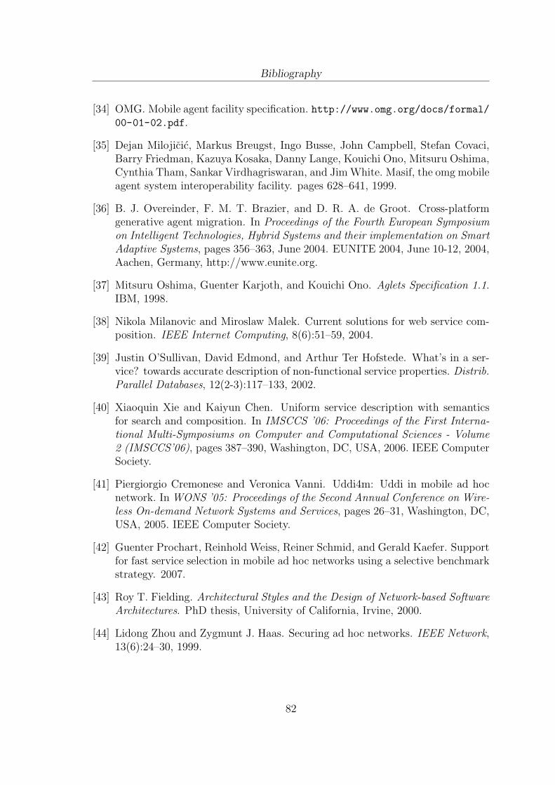
Bibliography
[34] OMG. Mobile agent facility specification. http://www.omg.org/docs/formal/00-01-02.pdf.
[35] Dejan Milojicic, Markus Breugst, Ingo Busse, John Campbell, Stefan Covaci,Barry Friedman, Kazuya Kosaka, Danny Lange, Kouichi Ono, Mitsuru Oshima,Cynthia Tham, Sankar Virdhagriswaran, and Jim White. Masif, the omg mobileagent system interoperability facility. pages 628–641, 1999.
[36] B. J. Overeinder, F. M. T. Brazier, and D. R. A. de Groot. Cross-platformgenerative agent migration. In Proceedings of the Fourth European Symposiumon Intelligent Technologies, Hybrid Systems and their implementation on SmartAdaptive Systems, pages 356–363, June 2004. EUNITE 2004, June 10-12, 2004,Aachen, Germany, http://www.eunite.org.
[37] Mitsuru Oshima, Guenter Karjoth, and Kouichi Ono. Aglets Specification 1.1.IBM, 1998.
[38] Nikola Milanovic and Miroslaw Malek. Current solutions for web service com-position. IEEE Internet Computing, 8(6):51–59, 2004.
[39] Justin O’Sullivan, David Edmond, and Arthur Ter Hofstede. What’s in a ser-vice? towards accurate description of non-functional service properties. Distrib.Parallel Databases, 12(2-3):117–133, 2002.
[40] Xiaoquin Xie and Kaiyun Chen. Uniform service description with semanticsfor search and composition. In IMSCCS ’06: Proceedings of the First Interna-tional Multi-Symposiums on Computer and Computational Sciences - Volume2 (IMSCCS’06), pages 387–390, Washington, DC, USA, 2006. IEEE ComputerSociety.
[41] Piergiorgio Cremonese and Veronica Vanni. Uddi4m: Uddi in mobile ad hocnetwork. In WONS ’05: Proceedings of the Second Annual Conference on Wire-less On-demand Network Systems and Services, pages 26–31, Washington, DC,USA, 2005. IEEE Computer Society.
[42] Guenter Prochart, Reinhold Weiss, Reiner Schmid, and Gerald Kaefer. Supportfor fast service selection in mobile ad hoc networks using a selective benchmarkstrategy. 2007.
[43] Roy T. Fielding. Architectural Styles and the Design of Network-based SoftwareArchitectures. PhD thesis, University of California, Irvine, 2000.
[44] Lidong Zhou and Zygmunt J. Haas. Securing ad hoc networks. IEEE Network,13(6):24–30, 1999.
82

Bibliography
[45] Sofiene Jelassi and Habib Youssef. Adaptive playback algorithm for interactiveaudio streaming over wireless ad-hoc networks. In IWCMC ’06: Proceedingsof the 2006 international conference on Wireless communications and mobilecomputing, pages 218–226, New York, NY, USA, 2006. ACM.
[46] Imad Jawhar and Jie Wu. Qos support in tdma-based mobile ad hoc networks.J. Comput. Sci. Technol., 20(6):797–810, 2005.
[47] W3C. Scalable vector graphics (svg) 1.1 specification. http://www.w3.org/
TR/SVG, 2003.
[48] Antoine Quint. Scalable vector graphics. IEEE Multimedia, 10(3):99–102, jul–sep 2003.
[49] Sun lively project. http://research.sun.com/projects/lively/.
[50] W3C. Mobile svg profiles: Svg tiny and svg basic. http://www.w3c.org/TR/
SVGMobile, 2003.
[51] Welch, Ken Jones, and Jeffrey Hobbs. Practical Programming in Tcl & Tk.Prentice Hall Professional Technical Reference, 2003.
[52] Linda Dailey Paulson. Developers shift to dynamic programming languages.Computer, 40(2):12–15, 2007.
[53] J.-L. Bakker and R. Jain. Next Generation Service Creation Using XML Script-ing Languages, volume 4. 2002.
[54] ECMA International. Standard ECMA-262. 1999.
83