an mda method for automatic transformation of models...
TRANSCRIPT
American Journal of Software Engineering and Applications 2015; 4(1): 1-14
Published online March 10, 2015 (http://www.sciencepublishinggroup.com/j/ajsea)
doi: 10.11648/j.ajsea.20150401.11
ISSN: 2327-2473 (Print); ISSN: 2327-249X (Online)
An MDA Method for Automatic Transformation of Models from CIM to PIM
Abdelouahed Kriouile, Najiba Addamssiri, Taoufiq Gadi
LAVETE Laboratory, Hassan 1 University, Settat, Morocco
Email address: [email protected] (A. Kriouile), [email protected] (N. Addamssiri), [email protected] (T. Gadi)
To cite this article: Abdelouahed Kriouile, Najiba Addamssiri, Taoufiq Gadi. An MDA Method for Automatic Transformation of Models from CIM to PIM.
American Journal of Software Engineering and Applications. Vol. 4, No. 1, 2015, pp. 1-14. doi: 10.11648/j.ajsea.20150401.11
Abstract: The Model Driven Architecture (MDA) approach introduces a clear separation of the business logic from the
implementation logic that's less stable. It uses the models that are more perennial than codes. It puts the models at the centre of
the development of software and of the information systems. The MDA approach consists at, firstly, developing the CIM
Model, secondly, obtaining the PIM model from the CIM, and finally generating the PSM model from the PIM which
facilitates the generation of code for a chosen technical platform. In the literature, several works have summarized the MDA
approach to the passage from PIM to PSM then from the PSM to code. Yet, very little work has contributed in the axis of the
CIM to PIM transformation, and their approaches generally propose a CIM model which does not cover the different
specifications of the Object Management Group (OMG) and/or the CIM to PIM transformation that they define is in the most
cases manual or semi-automatic. Thus, our proposal aims at providing a solution to the problem of constructing CIM and its
automatic transformation at the PIM using the QVT transformation rules. The approach proposes to represent CIM by two
models: The business process model reflecting both the static and the behavioral views of the system, and the functional
requirement model defined by the use case model reflecting the functional view of the system. The transformation of the CIM
allows us to generate the PIM level represented by two models: The domain classes model which gives a structural view of the
system at this level, and a model that describes the behavior of the system to each use case.
Keywords: MDA, CIM, PIM, Model Transformation, BPMN, QVT
1. Introduction
The discipline of software engineering has allowed the
development of computer systems for more and more
complex and requiring enormous investments. Yet, the
sustainability of these systems is questioned whenever a new
technology appears, since each new technology put in place a
set of tools that, generally, does not support the older
technologies.
However, in response to this difficult situation, we should
reconsider the reduction of the cost of development work that
is done independently from the target technology and which
is, therefore, connected to the business logic of the
application. The MDA approach (Model Driven Architecture)
[1] is called by introducing a clear separation of the business
logic -which is stable and undergoes little changes over time-
from the implementation logic that's less stable; models are
more perennial than codes. This MDA approach fits into the
overall context of the Model Driven Engineering (MDE),
which puts the models at the centre of the development of
software and of the information systems.
The principle of the MDA approach is based on the use of
models and metamodels for the various phases of the software
development lifecycle. Specifically, it recommends three types
of models from different viewpoints) [1]: The Computation
Independent Model (CIM), the Platform Independent Model
(PIM) and the Platform Specific Model (PSM).
The MDA approach consists, at first, to develop the CIM
Model. Secondly, to obtain the PIM model from the CIM,
and finally to generate the PSM model from the PIM which
facilitates the generation of code for a chosen technical
platform. The passage from CIM to PIM and from PIM to
PSM represents models transformations, while the generation
of code from PSM is not regarded as a model transformation.
Ideally, according to [1], the code generation can be done
automatically by successive transformations of models: CIM
to PIM, PIM to PSM and PSM to code.
In the literature, several works have summarized the MDA
approach to the passage from PIM to PSM then from the
2 Abdelouahed Kriouile et al.: An MDA
PSM to code. Yet, very little work have contributed in the
axis of the CIM to PIM transformation, and their approaches,
generally, propose a CIM model which does not cover the
different specifications of the Object Management Group
(OMG) and/or the CIM to PIM transformation that they
define is in the most cases manual or semi-automatic.
Thus, our proposal aims to be a new solution to the
problem of constructing CIM and its automatic
transformation at the PIM. This problem can be divided into
two sub-problems:
� Elaborate a CIM model conforms to the various
specifications outlined by the OMG.
� Define an automatic model transformation allowing
generating the PIM model conform to the various
specifications outlined by the OMG.
Thus, our initiative aims at solving or at least mitigating
in the context of the MDA approach- the problems related to
the sustainability of the applications. This sustainability
cannot be ensured only through models that are sustainable
and productive, independent from computing and
independent from any technological platform. Our
contribution seeks to solve this problem at top level of the
MDA; it will specifically focus on modeli
define the transformation rules allowing generating the
suitable PIM Model from the CIM Model. The
transformations rules are expressed through language QVT.
In our approach, we propose to represent CIM by two
models: The business process model (BPM) reflecting both
the static aspect (Static View) and the behavioral aspect
(Behavioral View) of the system, and the functional
requirement model defined by the Use C
reflecting the functional aspect (Functional View) of the
system.
The transformation of the CIM allows us to generate the
PIM model represented by two models: The domain classes
model corresponds to the context in which the system should
be applied which gives a static view of system (Structural
View), and the Behavioral Model that describes the behavior
of the system to each use case providing a behavioral view of
system (Behavioral View).
The rest of this paper is organized as follows. In
background and related work for this research are explained.
Section 3 and section 4 depict respectively how the CIM and
PIM will model. Section 5 presents the different steps of our
method to construct CIM and to transform it automatically
into PIM using the QVT transformation rules. In
we shall present an illustrative case study. The analysis of the
evaluation results of our proposal is explained in
Finally, in section 8, we briefly provide a conclusion and
present our plan for future works.
2. Background and Related W
2.1. Levels of Modeling in MDA
The OMG announced its initiative MDA (Model Driven
Architecture) in November 2000, then proposed its first
An MDA Method for Automatic Transformation of Models from CIM to PIM
PSM to code. Yet, very little work have contributed in the
axis of the CIM to PIM transformation, and their approaches,
model which does not cover the
Object Management Group
and/or the CIM to PIM transformation that they
automatic.
Thus, our proposal aims to be a new solution to the
constructing CIM and its automatic
transformation at the PIM. This problem can be divided into
Elaborate a CIM model conforms to the various
Define an automatic model transformation allowing
the PIM model conform to the various
Thus, our initiative aims at solving or at least mitigating -
the problems related to
the sustainability of the applications. This sustainability
annot be ensured only through models that are sustainable
and productive, independent from computing and
independent from any technological platform. Our
contribution seeks to solve this problem at top level of the
MDA; it will specifically focus on modeling the CIM and
define the transformation rules allowing generating the
suitable PIM Model from the CIM Model. The
transformations rules are expressed through language QVT.
In our approach, we propose to represent CIM by two
el (BPM) reflecting both
the static aspect (Static View) and the behavioral aspect
(Behavioral View) of the system, and the functional
Case model (UC)
reflecting the functional aspect (Functional View) of the
ws us to generate the
odel represented by two models: The domain classes
model corresponds to the context in which the system should
be applied which gives a static view of system (Structural
odel that describes the behavior
of the system to each use case providing a behavioral view of
The rest of this paper is organized as follows. In section 2,
background and related work for this research are explained.
ection 4 depict respectively how the CIM and
will model. Section 5 presents the different steps of our
method to construct CIM and to transform it automatically
the QVT transformation rules. In section 6,
ive case study. The analysis of the
evaluation results of our proposal is explained in section7.
ection 8, we briefly provide a conclusion and
Work
OMG announced its initiative MDA (Model Driven
Architecture) in November 2000, then proposed its first
version in 2001 and in 2003 adopted the final specification of
the approach [2]. The MDA approach fits into the overall
context of the model driven engineering (MDE), which puts
the models at the centre of the development of software and
of the information systems.
Since the models are more perennial than codes, and in
order to enable the organizations to evolve their applicat
models independently of the evolution of the technology
platforms, MDA advocates the elaboration of perennial models
by distinguishing models which are independent from the
platforms of the models that are specific to platforms. Thus, its
principle is to separate the functional specifications from the
implementation specifications on a particular platform.
The MDA approach offers three types of models from
three different points of view [1]
� CIM (Computation Independent Mod
independent of any computerization. The CIM Model
does not show the details of the system structure. It
describes the product independently of any computer
system. It focuses on the requirements of the system as
well as the environment in
going into the details of its structure and its
implementation. It is sometimes called a domain model
and serves as the vocabulary for system domain
practitioners. However, a CIM is more than a domain
model; it expresses also the
� PIM (Platform Independent Model): It refers to a view
of system or sub-system at an abstraction level allowing
an independence from any technical platform. The role
of the PIM is to be perennial and to make the link
between the CIM and the PSM model. The MDA
approach advocates the use of UML as a language to
model the PIM. But it gives neither any indication of the
number of models to develop at the PIM level nor the
method to be used for developing it.
� PSM (Platform Specific
model of the technical platforms. It mainly serves as a
base for generating an executable code on the chosen
technical platform. It indicates how the product will be
used on these platforms. A good PSM must incorporate
enough features and concepts (data types, classes,
interfaces, patterns, etc.) of the platform chosen to make
the code generation easy.
Figure 1. MDA software lifecycle
Method for Automatic Transformation of Models from CIM to PIM
version in 2001 and in 2003 adopted the final specification of
. The MDA approach fits into the overall
text of the model driven engineering (MDE), which puts
the models at the centre of the development of software and
Since the models are more perennial than codes, and in
order to enable the organizations to evolve their application
models independently of the evolution of the technology
platforms, MDA advocates the elaboration of perennial models
by distinguishing models which are independent from the
platforms of the models that are specific to platforms. Thus, its
to separate the functional specifications from the
implementation specifications on a particular platform.
The MDA approach offers three types of models from
[1]:
CIM (Computation Independent Model): It’s a model
independent of any computerization. The CIM Model
does not show the details of the system structure. It
describes the product independently of any computer
system. It focuses on the requirements of the system as
well as the environment in which it operates without
going into the details of its structure and its
implementation. It is sometimes called a domain model
and serves as the vocabulary for system domain
practitioners. However, a CIM is more than a domain
model; it expresses also the requirements of the system.
PIM (Platform Independent Model): It refers to a view
system at an abstraction level allowing
an independence from any technical platform. The role
of the PIM is to be perennial and to make the link
CIM and the PSM model. The MDA
approach advocates the use of UML as a language to
model the PIM. But it gives neither any indication of the
number of models to develop at the PIM level nor the
method to be used for developing it.
PSM (Platform Specific Model): It is the dependent
model of the technical platforms. It mainly serves as a
base for generating an executable code on the chosen
technical platform. It indicates how the product will be
used on these platforms. A good PSM must incorporate
atures and concepts (data types, classes,
interfaces, patterns, etc.) of the platform chosen to make
MDA software lifecycle

American Journal of Software Engineering and Applications 2015;
2.2. Model Transformations in MDA
The main artifacts of the MDA are models and model
transformations. Generally, we call transformation of models
any program which its inputs and outputs are models
respectively conform to their metamodels. A model
transformation matches, according to the transformation rules,
the concepts of the source and the target metamodel. The
transformation rules are described at the transformation
models conform in turn to the metamodel that defines the
transformation language. Thus, the elements of the target
models can be generated from those of the sources models
applying transformation rules that are already defined.
In the MDA architecture the MOF (Meta Object Facility)
allows the definition of modeling languages, as well as the
definition of the transformation rules. It is normalized by the
OMG in its current version 2.0 [3]. It is used to specify the
structure and syntax of metamodels. It also specifies
mechanisms for metamodel interoperability, allowing its
comparing and its linking. Thanks to these exchange
mechanisms, the MOF cohabit different metamodels.
The OMG proposes the standard MOF 2.0 QVT (Query
View Transformation) [3] as language to define the
transformation of models.
Figure 2. MDA processing Process
2.3. Business Process Modelling
BPMN and UML activity diagram are two competing
standards, both maintained by the OMG, allowing to model
business processes.
BPMN is based on a single Business Processes Diagram,
called BPD [4]. It is easy to use and to understand,
modeling the complex business processes.
The UML AD specification does not deal with the
business process modeling. It mentioned that the activities
can be applied to organizational modeling for business
processes engineering and workflows [5]
UML activity diagrams can be used to model business
processes, or the dynamic part of a model (e.g. an algorithm
of an operation). They can represent a process, or the
behavior of an operation.
American Journal of Software Engineering and Applications 2015; 4(1): 1-1
The main artifacts of the MDA are models and model
transformations. Generally, we call transformation of models
any program which its inputs and outputs are models
respectively conform to their metamodels. A model
transformation matches, according to the transformation rules,
the target metamodel. The
transformation rules are described at the transformation
models conform in turn to the metamodel that defines the
transformation language. Thus, the elements of the target
models can be generated from those of the sources models by
applying transformation rules that are already defined.
In the MDA architecture the MOF (Meta Object Facility)
allows the definition of modeling languages, as well as the
definition of the transformation rules. It is normalized by the
. It is used to specify the
structure and syntax of metamodels. It also specifies
mechanisms for metamodel interoperability, allowing its
comparing and its linking. Thanks to these exchange
ohabit different metamodels.
The OMG proposes the standard MOF 2.0 QVT (Query
as language to define the
MDA processing Process
and UML activity diagram are two competing
standards, both maintained by the OMG, allowing to model
BPMN is based on a single Business Processes Diagram,
It is easy to use and to understand, allowing
modeling the complex business processes.
The UML AD specification does not deal with the
business process modeling. It mentioned that the activities
can be applied to organizational modeling for business
[5]. But practically
UML activity diagrams can be used to model business
processes, or the dynamic part of a model (e.g. an algorithm
of an operation). They can represent a process, or the
A comparison between the Business Process Diagram
(BPD) and the UML Activity Diagrams for modeling of
twenty-one workflows patterns are introduced in
shows enough similarity between the two diagrams in terms
of notations and the repres
benefits are provided by the BPMN, its mathematical
foundations designed to easily transform it in a business
language. Furthermore, BPMN can be translated into UML
and provide a solid modeling mean.
2.4. Related Work
Several methods of modeling and transformation of
models have been proposed in the context of the MDA.
However, through the bibliographical study that we have
conducted only seven methods seem to address the
modeling of the CIM level and its transformation
PIM level.
The authors in [7] proposed a disciplined method for
transformation of CIM to PIM. The CIM model uses two
activity diagrams to represent business processes and
system requirements. The business process model
represents all the activities of the organization
independently of their automation; while the requirements
model specifies the system supporting such activities, by
representing their use cases and considering it as a one actor.
The PIM model is represen
obtained from the requirements model. This last model is
transformed into component models of the system that
provide a first sketch of the structure of the system: a set of
business archetypes that helps to transform, in detail, t
components system into PIM. This approach is based on
modeling the CIM using the UML 2.0 Activity Diagrams as
a single technique, and the PIM behavioral aspect is not
specified.
The method in [8] proposed a CIM to PIM
transformation using a method oriented by the features and
based on components. The requirements in the CIM model
are represented by a model that includes a set of features
and relations between them. And the PIM model is
represented by a software architecture
components and their interactions. This method uses an
intermediate model that is neither CIM nor PIM, which
does not consider business processes.
In the papers [9, 10, 11],
composed by a business processes
business process with the BPMN. This CIM is transformed,
with the help of the QVT rules
(Query/View/Transformation), checklists, and refinement
rules into two models composing the PIM level: the use
cases diagram and the class diagra
detailed in order to obtain the activities and the class
diagram that is considered an initial analysis model. Use
cases diagram is moved, in this method, into the PIM level.
Furthermore, the diagrams of the PIM that are obtained by
transformation of the CIM, do not communicate the PIM
behavioral structure.
Paper [12] presents an analytical solution for the
14 3
een the Business Process Diagram
(BPD) and the UML Activity Diagrams for modeling of
one workflows patterns are introduced in [6]. It
shows enough similarity between the two diagrams in terms
of notations and the representations. However, other
benefits are provided by the BPMN, its mathematical
foundations designed to easily transform it in a business
language. Furthermore, BPMN can be translated into UML
and provide a solid modeling mean.
Several methods of modeling and transformation of
models have been proposed in the context of the MDA.
However, through the bibliographical study that we have
conducted only seven methods seem to address the
modeling of the CIM level and its transformation to the
proposed a disciplined method for
transformation of CIM to PIM. The CIM model uses two
activity diagrams to represent business processes and
system requirements. The business process model
represents all the activities of the organization
independently of their automation; while the requirements
model specifies the system supporting such activities, by
representing their use cases and considering it as a one actor.
The PIM model is represented by the class diagram
obtained from the requirements model. This last model is
transformed into component models of the system that
provide a first sketch of the structure of the system: a set of
business archetypes that helps to transform, in detail, the
components system into PIM. This approach is based on
modeling the CIM using the UML 2.0 Activity Diagrams as
a single technique, and the PIM behavioral aspect is not
proposed a CIM to PIM
formation using a method oriented by the features and
based on components. The requirements in the CIM model
are represented by a model that includes a set of features
and relations between them. And the PIM model is
represented by a software architecture that includes a set of
components and their interactions. This method uses an
intermediate model that is neither CIM nor PIM, which
does not consider business processes.
, the authors present a CIM
composed by a business processes model, using a secured
business process with the BPMN. This CIM is transformed,
with the help of the QVT rules
(Query/View/Transformation), checklists, and refinement
rules into two models composing the PIM level: the use
cases diagram and the class diagram. The use cases are
detailed in order to obtain the activities and the class
diagram that is considered an initial analysis model. Use
cases diagram is moved, in this method, into the PIM level.
Furthermore, the diagrams of the PIM that are obtained by
ansformation of the CIM, do not communicate the PIM
presents an analytical solution for the
4 Abdelouahed Kriouile et al.: An MDA Method for Automatic Transformation of Models from CIM to PIM
modeling of CIM and its transformation to the PIM model.
To model business processes, the authors used at the CIM
level the Data Flow Diagrams (DFD). Whereas the PIM
level is covered by four UML diagrams: The Use Cases
Diagram, The Activities Diagram, The Sequence Diagrams
and the Domain Models.
Paper [13] tackles a semi-automatic method for building
web applications from the high level of requirements,
expressed as use cases in accordance with the model-driven
architecture (MDA). The first step of the method is to
transform the CIM model to the PIM model. It considers
that the CIM is represented by the description of use cases
as well as the default domain objects. The PIM model
includes State Machines, the User Interface Model and the
refined domain model. This method does not consider
business processes.
In paper [14] the authors present a systematic method for
MDA transformations, including the creation of the
platform independent model (PIM) from the CIM, the
transformation of the PIM to the platform specific model
(PSM) and the generation of code from the PSM model.
The CIM in this method is composed of the use cases
diagram, the activity diagram and the robustness diagram.
While, the PIM is modeled by two parts: the behavioral part
by a sequence diagrams and the structural part by a class
diagram.
The method in [15] allows, first, to build the CIM model
and to transform it (semi-) automatically to the less
abstraction level (PIM).The CIM level is covered by two
models; on one hand the business process model (BPM)
characterizing both the behavioral and the static aspects
representing the different activities and resources used by
them in the business processes. On the other hand, the use
cases model representing functional aspect of system.
While, the PIM level is modeled with the domain classes
diagram (DCD) and the external behavior sequence diagram
of the system (SDSEB). The later is an UML sequence
diagram that demonstrates interactions between the actors
and the system seen as unique entity represented by a one
line of life, without focus on the interactions of the objects
system. This method calls the business rules to generate the
DCD PIM level.
It should be noted that in the literature we have found
two other proposals that are limited only to the modeling of
the CIM level, without giving details on its transformation
into PIM. The method in paper [16] presents a method for
modeling CIM based on the artifacts and the concepts of the
RUP methodology. This method presents a CIM which
covers two aspects: the business processes and requirements.
It is composed of three models: A business use cases model,
a business analyses model and the use cases model.
Moreover, the method in the papers [17, 18, 19], called
TFMfMDA (Topological Functioning Modeling for Model
Driven Architecture) using formal mathematical
foundations of topological functioning model. The CIM
level is modeled with use cases model and the conceptual
class diagram presenting the domain concepts and their
relations to establish.
3. CIM Architecture
The creation of the CIM is the first task in the MDA
development process. It must be developed in collaboration
with the domain experts. The CIM is of great importance for
the rest of the development process; any changes driven by
new requirements at the CIM level will reflect the PIM and
the PSM levels.
3.1. Specifications of CIM According to the OMG
According to the definition given by the OMG [1], we
have deduced that the CIM model must verify the following
requirements:
� CIM represents a point of view of the system
independently of the computation.
� CIM should not show the details of the structure of the
system.
� CIM is sometimes called domain model or a business
model, using for its specification, the current vocabulary
of practitioners of domain in question.
� Since the primary user of the CIM -the practitioner of
domain- is generally not a know-all of models or of the
artifacts used to make features for which the
requirements are identified in the CIM. The CIM must
play an important role in bridging the gap between the
domain experts with its requirements and the experts of
the design and construction of objects which must
satisfy the domain requirements.
� The system requirements are modeled in the CIM.
� CIM describes the situation in which the system will be
used.
� CIM is independent of the system implementation. It
hides many or all of the information on the use of data
automatic processing systems.
� CIM represents a source of common vocabulary to use
in other models of the MDA.
� The requirements of the CIM must be traceable to the
artifacts of the PIM and the PSM, and vice versa.
� CIM can include several models, some providing more
details than others or focused on specific preoccupations.
3.2. Architecture of CIM in our Approach
According to Xavier Blanc [20], in a wider context, the
requirements model (CIM) is considered as a complex entity,
constituted by a glossary, the definitions of business
processes, the requirements, and the use cases as well as a
systemic view of application.
By analyzing the related works previously presented, there
is no consensus on the number and types of elements
constituting the CIM. In order to propose an appropriate CIM
from previous requirements, our proposal suggests that the
CIM must compose of two models: the BPMN Diagram, to
describe the different business processes represented by
different sequences of activities, and the use cases diagram
American Journal of Software Engineering and Applications 2015; 4(1): 1-14 5
(UCD) allowing in turn the description of the requirements in
the CIM level.
The system, at this level, is seen as black box to ensure the
independence of any computation by hiding the details of the
structure of the system.
A refinement between the two models (BPMN and UC)
allows us, on one hand, to have the same vision between
domain experts and technological ones and on the other hand
to validate the CIM level before any transformation into the
low levels of MDA.
3.2.1. Business Process Diagram (BPD)
A business process represents the interactions in the form
of exchange of information between various actors: humans,
applications or services and third-party processes.
Business Process Model and Notation (BPMN) is a
graphical notation used to specify and to model business
processes. Its main objective is to provide a standard notation
that is easily understandable by all actors of the organization.
It is a business model using a simple notation for domain
practitioners, facilitating communication between experts of
the domain and requirements, and technical experts. It shows
the system in its environment.
The BPMN model called BDP (Business Process Diagram)
consists of a small set of graphic elements classed into four
categories: Flow Objects, Connecting Objects, Swimlanes
and Artifacts [21].
Figure 3 illustrates the main fragment of the BPMN
metamodel.
Figure 3. Main fragment of the meta-model BPMN
3.2.2. Use Cases Model (UML UC)
Use case diagrams allow identifying the features of a
system and the conditions for their good functioning. They
show functional elements, actors and objects in interaction.
To this end, a use case diagram contains actors and use
cases.
An actor is an entity that can interact with the system;
whereas, a use case is a set of interactions between some
actors and the system under development.
UML (Unified Modeling Language) defines a use case
as : “the specification of a set of actions performed by a
system, which yields an observable result that is, typically,
of value for one or more actors or other stakeholders of the
system" [5].
The use cases are not enchained. There is no temporal
representation in a use case diagram. Each use case can be
described in detail, describing the interactions between
actors and the system, and the order in which they occur.
Several techniques exist for the detailed description of a use
case, such as state machines, activity diagrams, or informal
text. For our proposed method, we use the textual
description (TD) of use cases that we formalize using
SBVR (Semantic Business Vocabulary and Business Rules)
[22].
We adopt the use cases diagrams for several reasons:
� Use cases diagrams play a very important role for the
identification of the requirements of the users. They
describe exhaustively the functional requirements of
the system.
� Because of their simplicity, the analysts and the
developers are familiar with the use of the use cases
diagrams.
� The existence of the development process guided by
the different cases, such as the Unified Process (UP)
described by the authors of UML [23] and the Rational
Unified Process (RUP) [24] that adheres to good
6 Abdelouahed Kriouile et al.: An MDA Method for Automatic Transformation of Models from CIM to PIM
development practices observed in the industry for
their success.
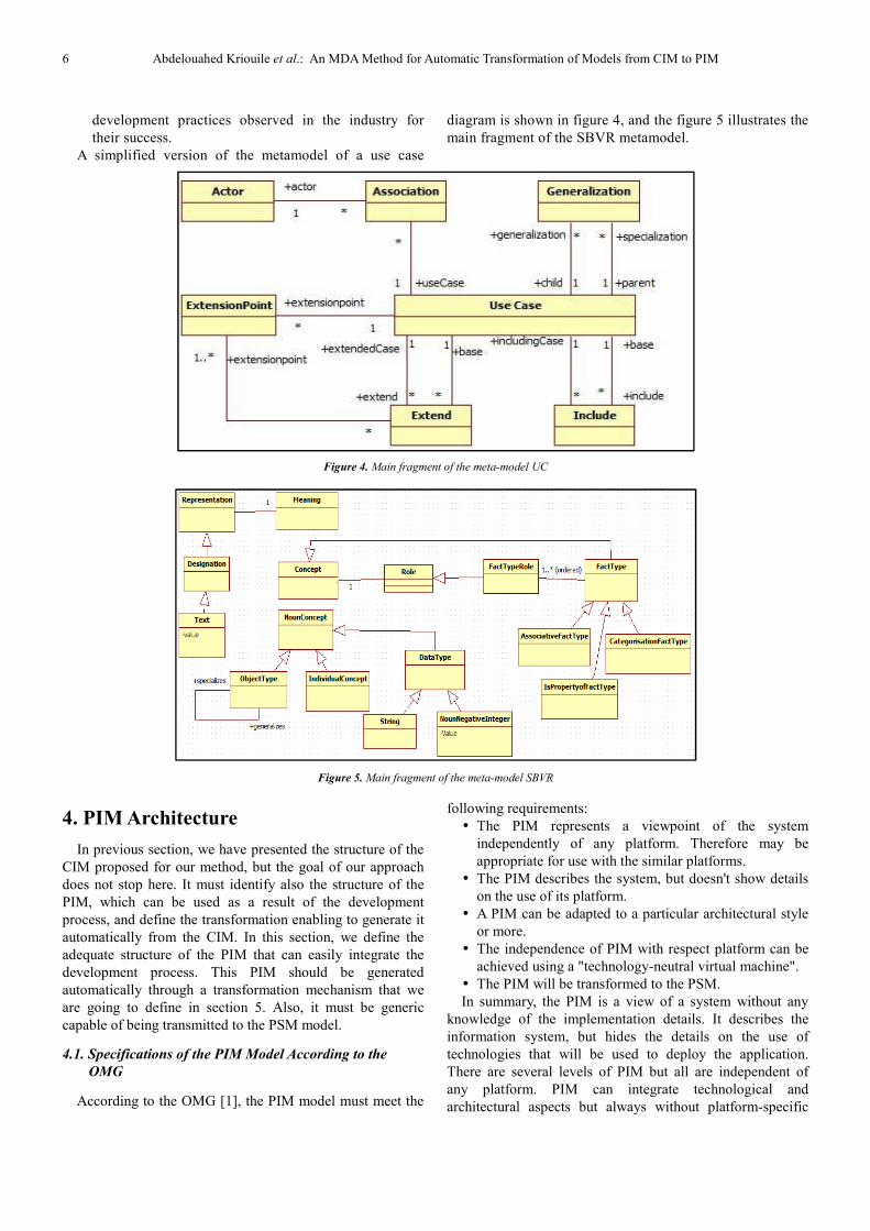
A simplified version of the metamodel of a use case
diagram is shown in figure 4, and the figure 5 illustrates the
main fragment of the SBVR metamodel.
Figure 4. Main fragment of the meta-model UC
Figure 5. Main fragment of the meta-model SBVR
4. PIM Architecture
In previous section, we have presented the structure of the
CIM proposed for our method, but the goal of our approach
does not stop here. It must identify also the structure of the
PIM, which can be used as a result of the development
process, and define the transformation enabling to generate it
automatically from the CIM. In this section, we define the
adequate structure of the PIM that can easily integrate the
development process. This PIM should be generated
automatically through a transformation mechanism that we
are going to define in section 5. Also, it must be generic
capable of being transmitted to the PSM model.
4.1. Specifications of the PIM Model According to the
OMG
According to the OMG [1], the PIM model must meet the
following requirements:
� The PIM represents a viewpoint of the system
independently of any platform. Therefore may be
appropriate for use with the similar platforms.
� The PIM describes the system, but doesn't show details
on the use of its platform.
� A PIM can be adapted to a particular architectural style
or more.
� The independence of PIM with respect platform can be
achieved using a "technology-neutral virtual machine".
� The PIM will be transformed to the PSM.
In summary, the PIM is a view of a system without any
knowledge of the implementation details. It describes the
information system, but hides the details on the use of
technologies that will be used to deploy the application.
There are several levels of PIM but all are independent of
any platform. PIM can integrate technological and
architectural aspects but always without platform-specific

American Journal of Software Engineering and Applications 2015; 4(1): 1-14 7
details. It can contain, for example, information about
security, persistence, etc. That allows more precisely to
project the PIM model towards a specific model PSM.
4.2. Architecture of the PIM Model in Our Approach
The PIM, called Model of analysis and design, represents
the business logic specific for a system. It depicts the
functioning of entities and services. It must be sustainable
over time.
The UML language is imposed today as a reference for
realizing all analysis and design models. At this level we are
interested in an abstract design, realizable without any
knowledge of the techniques implementation. Thus, the
application of the design patterns or the GoF (Gang of Four)
is part of this stage of design. Nevertheless, the application of
technical patterns, specific for some platforms, corresponds
to a next step [20].
So, an adequate PIM should represent two aspects of the
system:
� The structural aspect (static) of the system using classes,
objects, attributes, operations, relations, etc.
� The behavioral aspect of the system showing the
interactions between objects, etc.
At this level, the formalism used to express the PIM is a
domain class diagram coupled with a system sequence
diagram expressed in UML.
4.2.1. Domain Classes Diagram (DCD)
A domain model is not a description of software objects
but a visualization of the concepts of a real-world domain.
We speak about the analysis objects. It is possible that an
analysis object becomes a software object during the design,
but this is not systematic.
Domain class diagram should not be confused with a
design class diagram. A domain class diagram can be
enriched with methods obtained from the different interaction
diagrams, such as the sequence diagram or a state-machine
diagram for obtaining the design class diagram that contains
classes with the signatures of their methods.
An UML class diagram will be used to represent the
domain model. It can contain only the classes and some
attributes without specification of the operations.
The domain class diagram represents in our approach the
static view of the PIM.
Figure 6. Simplified metamodel of Domain Class Diagram
4.2.2. System Sequence Diagram (SSD)
The objective of the system sequence diagrams (DSS) is to
describe the behavior of the system where it is seen as a
'black box' (from the analysis point of view). The system is
thus seen from the outside (by actors) without prejudice to
how it will be achieved. The 'black box' will be open
(described) to a subsequent design phase. The process of a
use case will be described as a sequence of messages
exchanged between the actors and the system.
Figure 7. Main fragment of the System Sequence Diagram Meta-model
Figure 8. Overview of the process of transformation of the CIM to PIM
5. Steps of Transformation Approach
from CIM to PIM
This section presents the approach for CIM modeling and
its transformation to the PIM model.
Our approach consists of three steps:
� Step 1: Modeling CIM through the BPMN model (BPD)
and the of use cases model (UML UC) obtained by the
horizontal transformation CIM2CIM (figure 9) from the
first model BPD.
� Step 2: Obtain from the CIM, the behavioral view of the
PIM represented by a System Sequence Diagram (UML
SSD). This step is assured by the vertical transformation
CIM2PIM noted C2P1 in the remainder of the paper, as
shown in figure 8. This step has been detailed in our
Class
AssociationClassifier
Property
PrimitveType
DataType
Enumeration
1
2..*
0..1
*
0..*
1..1 10..1
8 Abdelouahed Kriouile et al.: An MDA Method for Automatic Transformation of Models from CIM to PIM
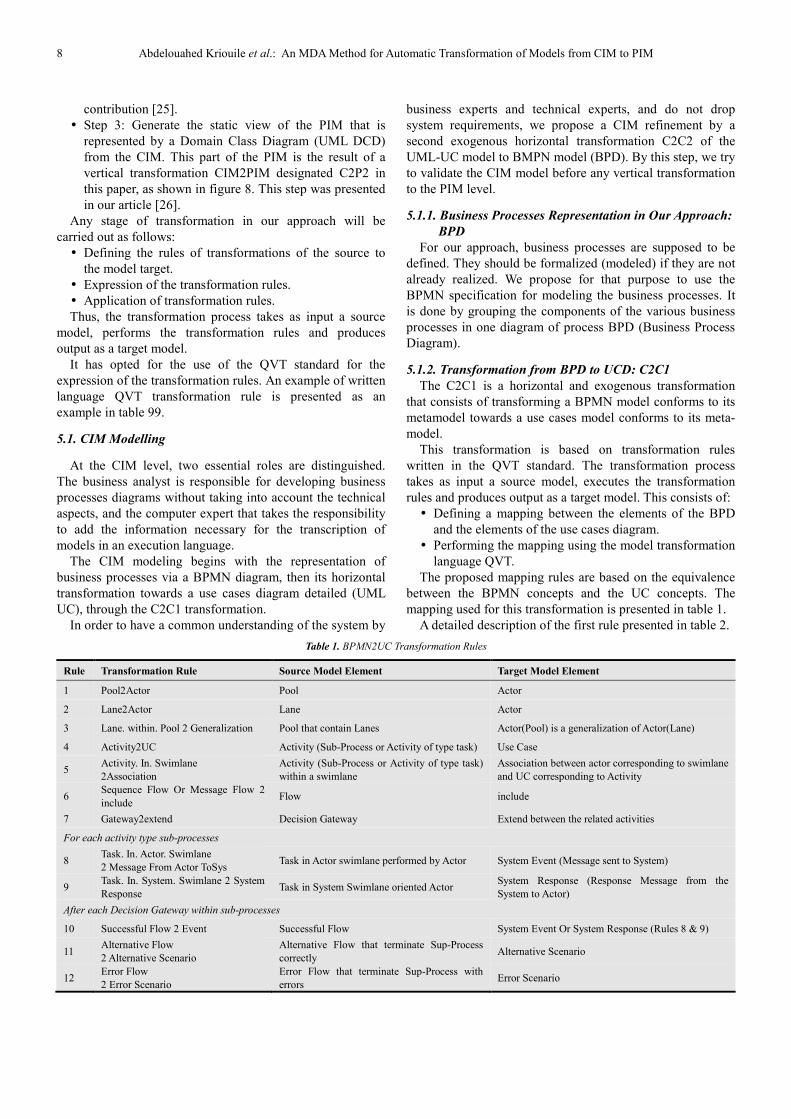
contribution [25].
� Step 3: Generate the static view of the PIM that is
represented by a Domain Class Diagram (UML DCD)
from the CIM. This part of the PIM is the result of a
vertical transformation CIM2PIM designated C2P2 in
this paper, as shown in figure 8. This step was presented
in our article [26].
Any stage of transformation in our approach will be
carried out as follows:
� Defining the rules of transformations of the source to
the model target.
� Expression of the transformation rules.
� Application of transformation rules.
Thus, the transformation process takes as input a source
model, performs the transformation rules and produces
output as a target model.
It has opted for the use of the QVT standard for the
expression of the transformation rules. An example of written
language QVT transformation rule is presented as an
example in table 99.
5.1. CIM Modelling
At the CIM level, two essential roles are distinguished.
The business analyst is responsible for developing business
processes diagrams without taking into account the technical
aspects, and the computer expert that takes the responsibility
to add the information necessary for the transcription of
models in an execution language.
The CIM modeling begins with the representation of
business processes via a BPMN diagram, then its horizontal
transformation towards a use cases diagram detailed (UML
UC), through the C2C1 transformation.
In order to have a common understanding of the system by
business experts and technical experts, and do not drop
system requirements, we propose a CIM refinement by a
second exogenous horizontal transformation C2C2 of the
UML-UC model to BMPN model (BPD). By this step, we try
to validate the CIM model before any vertical transformation
to the PIM level.
5.1.1. Business Processes Representation in Our Approach:
BPD
For our approach, business processes are supposed to be
defined. They should be formalized (modeled) if they are not
already realized. We propose for that purpose to use the
BPMN specification for modeling the business processes. It
is done by grouping the components of the various business
processes in one diagram of process BPD (Business Process
Diagram).
5.1.2. Transformation from BPD to UCD: C2C1
The C2C1 is a horizontal and exogenous transformation
that consists of transforming a BPMN model conforms to its
metamodel towards a use cases model conforms to its meta-
model.
This transformation is based on transformation rules
written in the QVT standard. The transformation process
takes as input a source model, executes the transformation
rules and produces output as a target model. This consists of:
� Defining a mapping between the elements of the BPD
and the elements of the use cases diagram.
� Performing the mapping using the model transformation
language QVT.
The proposed mapping rules are based on the equivalence
between the BPMN concepts and the UC concepts. The
mapping used for this transformation is presented in table 1.
A detailed description of the first rule presented in table 2.
Table 1. BPMN2UC Transformation Rules
Rule Transformation Rule Source Model Element Target Model Element
1 Pool2Actor Pool Actor
2 Lane2Actor Lane Actor
3 Lane. within. Pool 2 Generalization Pool that contain Lanes Actor(Pool) is a generalization of Actor(Lane)
4 Activity2UC Activity (Sub-Process or Activity of type task) Use Case
5 Activity. In. Swimlane
2Association
Activity (Sub-Process or Activity of type task)
within a swimlane
Association between actor corresponding to swimlane
and UC corresponding to Activity
6 Sequence Flow Or Message Flow 2
include Flow include
7 Gateway2extend Decision Gateway Extend between the related activities
For each activity type sub-processes
8 Task. In. Actor. Swimlane
2 Message From Actor ToSys Task in Actor swimlane performed by Actor System Event (Message sent to System)
9 Task. In. System. Swimlane 2 System
Response Task in System Swimlane oriented Actor
System Response (Response Message from the
System to Actor)
After each Decision Gateway within sub-processes
10 Successful Flow 2 Event Successful Flow System Event Or System Response (Rules 8 & 9)
11 Alternative Flow
2 Alternative Scenario
Alternative Flow that terminate Sup-Process
correctly Alternative Scenario
12 Error Flow
2 Error Scenario
Error Flow that terminate Sup-Process with
errors Error Scenario

American Journal of Software Engineering and Applications 2015; 4(1): 1-14 9
Table 2. QVT code of the first rule
Rule 1: Pool2Actor
Source Model Element
Target Model Element
: Pool
: Actor
Description:
In BPMN 2.0 [21] a "Pool" is a participant in a collaboration diagram. It can contain details or not. With details, it is a process. Without details, it acts as a
simple 'black box '.
An actor is a user type that always has the same behavior to a use case. The same physical person may behave in as many different players as the number of
roles it plays towards the system. Thus for example, a messaging system administrator might also be the same mail user. It will be considered as an actor of
the system: in the role of administrator, in the first hand, and in the role of user in the second hand. An actor can also be an external system with which the
use case will interact (Gabay & Gabay, 2008).
Therefore each "Pool" of the BPMN will be transformed into an "Actor" actor in the UC.
QVT Rule:
mapping Pool::PooltoActor (): Actor
{result.name: = self.name;}
result.UseCase += self.Activities.map
ActivitytoUseCase();
result.ChildActor += self.lanes.map
LanetoActor(); }
5.1.3. Transformation from UCD to BPD: C2C2
The C2C2 is a horizontal and exogenous transformation
that consists of transforming a use cases model conforms to
its meta-model to a BPMN model conforms to its metamodel.
Table 3 summarizes the rules used for C2C2 transformation.
Table 3. Use-Case to BPMN transformation QVT rule
Rule Transformation Rule Source Model Element Target Model Element
1 Actor2Lane Actor Lane
2 UC2Activity Use Case Activity (Sub-Process or Activity of type task)
3 Include2 SequenceFlow include Sequence Flow
4 Include 2MessageFlow Include Message Flow
5.2. Obtaining the PIM Behavioral Model from the CIM
The use case model obtained in the first step constitutes
the source of the CIM2PIM transformation, subsequently
noted C2P1, allowing the production of the model
representing the dynamic part of the PIM.
C2P1 is an exogenous and vertical transformation which
consists of transforming the UML-UC that is conformed to
its metamodel to a system sequence model which is
conformed to its metamodel. Thus, this transformation
consists of defining a mapping between the elements of the
UC model and elements representing the system sequence
diagram, and then to express the corresponding QVT
transformation rules. The proposed mapping rules are based
on the equivalence between the concepts of UML UC and the
concepts of the SSD. This mapping is presented in table 4.
Table 4. UC2SSD Transformation Rules
Rule Transformation Rule Source Model Element Target Model Element
1 UseCase2SSD Use Case SSD
2 Principal Actor 2Actor Actor that directly operates on the System Actor
3 System Event 2 System Message System Event (Message sent to System) Message sent From Actor to System
4 Sys Response
2SystemMessage
System Response (Response Message from
the System to Actor) Message sent From System to Actor
5 Internal Task 2 Internal Message Non-related system task to actor Internal System Message
6 Alternative Scenario 2 Alt Alternative Scenario Interaction Fragment ‘Alt’
7 Error Scenario 2 Break Error Scenario Interaction Fragment ‘Break’
5.3. Obtaining the PIM Static Model from the CIM
The CIM2PIM transformation, noted subsequently C2P2,
is defined by 6 transformation rules illustrated in table 4.
This exogenous and vertical transformation aims at
transforming the BPMN model that is conformed to its
metamodel to a domain classes model (UML DCD) which is
conformed to its metamodel. It specifies how one or more
elements of the BPMN model (source model) are
10 Abdelouahed Kriouile et al.: An MDA
transformed into one or more elements of the UML
model (target model).
The proposed mapping rules are based on the equivalence
Rule Transformation Rule
1 Pool 2 Class
2 Lane 2 Class
3 Lane. within. Pool 2 Aggregation
4 DataObject2Class
5 Activity 2 Operation
6 Group 2 Class
6. Case Study
With the aim to illustrate our method by an
have taken our case study presented in our previous work
[25, 26]. This example is based on a business process of
enrollment system for training in a school. It models the
interaction between customers and the school.
We have a one swimlane corresponding to ‘customers’ and
another one for the ‘school side’. However, since there are
Figure 9. Business Process Diagram of the case study “enrollment system for training”
Figure 10.
An MDA Method for Automatic Transformation of Models from CIM to PIM
transformed into one or more elements of the UML-DCD
e based on the equivalence
between the concepts of the BPMN and the concepts of the
DCD. This mapping is presented in table5.
Table 5. BPMN2DCD Transformation Rules
Source Model Element Target Model Element
Pool Class
Lane Class
Pool that contain Lanes Aggregation relationships between the Class derived from Pool
And the Classes derived from Lanes
Data Object Class
Activity Operation attached to the corresponding analysis class at the
container (Lane, Pool or Group)
Group Class
With the aim to illustrate our method by an example, we
have taken our case study presented in our previous works
his example is based on a business process of
enrollment system for training in a school. It models the
interaction between customers and the school.
orresponding to ‘customers’ and
another one for the ‘school side’. However, since there are
two actors involved in the former, we use a pool with two
lanes, one for each actor. Thus, within the school pool there
is a lane for an ‘Assistant’ and another for
Services’. Figure 9 depicts the process of our case study,
whereas figure 10 presents the detail of the first Sub
‘Choose Training’ using Data Objects as an example. It
employs two Pools, one for a customer and another one for a
system. In the same way we can represent the other sub
processes: ‘Order Training’, ‘Payment’, and ‘Training
Schedule’.
Business Process Diagram of the case study “enrollment system for training”
Figure 10. Diagram of Sub-Process “Choose Training”
Method for Automatic Transformation of Models from CIM to PIM
between the concepts of the BPMN and the concepts of the
DCD. This mapping is presented in table5.
Aggregation relationships between the Class derived from Pool
And the Classes derived from Lanes
Operation attached to the corresponding analysis class at the
container (Lane, Pool or Group)
two actors involved in the former, we use a pool with two
lanes, one for each actor. Thus, within the school pool there
is a lane for an ‘Assistant’ and another for ‘Financial
Services’. Figure 9 depicts the process of our case study,
whereas figure 10 presents the detail of the first Sub-Process
‘Choose Training’ using Data Objects as an example. It
employs two Pools, one for a customer and another one for a
In the same way we can represent the other sub-
processes: ‘Order Training’, ‘Payment’, and ‘Training
Business Process Diagram of the case study “enrollment system for training”

American Journal of Software Engineering and Applications 2015; 4(1): 1-14 11
Table 6. BPMN2UC Transformation Rules for the case study
Rule Use Cases Element
1 Pool 2 Actor Customer, School Area
2 Lane 2 Actor Assistant, Financial Services
3 Lane. within. Pool
2 Generalization ‘School Area’ Actor is a generalization for ‘Assistant’ actor and ‘Financial Services’ actor
4 Activity 2 UC Choose Training, Order Training, Pay Training, Receive Training Schedule, Receive Choice,
Receive Order Training, Send Schedule, Deliver Quotation, Validate Payment
5 Activity. In. Swimlane
2 Association
Each UC is associated at the Actor corresponding to the Swimlane. (For example : ‘Choose
Training’ is associated at ‘Customer’)
6 Sequence Flow Or Message Flow 2 include ‘Receive Choice’ include ‘Choose Training’
‘Deliver Quotation’ include ‘Receive Choice’’, …
7 Gateway 2 extend
‘Choose Training’ extend ‘Order Training’
‘Order Training’ extend ‘Pay Training’
‘Validate Payment’ extend ‘Send Schedule’
8 Task. In. Actor. Swimlane
2 Message From Actor ToSys
Request Training Catalog
Fill Form Training needs
Quotation Request
9 Task. In. System. Swimlane 2 System
Response Deliver Training Catalog, Accepted Form Training, Quotation Deliver
10 Successful Flow 2 Event Choice in Catalog
11 Alternative Flow
2 Alternative Scenario Specific Choice
12 Error Flow2 Error Scenario Cancel Choice
The Use Cases Diagram obtained by applying the C2C1 transformation rules is shown in figure 11 below. Table 12 shows
the C2P1 transformation rules corresponding to a Sub-Process “choose training”.
Figure 11. Use Cases Diagram of the Case Study
System
Order Training
QuotationAcceptedextension points
Customer Assistant
Financial Services
Pay Training
OrderMadeextension points
Receive Training Schedule
Choose Training
Send Schedule
PaymentValidatedextension points
Validate Payement
Deliver Quotation
Receive Choice
Receive Order Training
<<include>>
<<include>>
<<include>>
<<include>>
School Area<<extend>>
<<extend>>
<<include>>
<<include>>
<<include>>
<<extend>><<include>>
12 Abdelouahed Kriouile et al.: An MDA Method for Automatic Transformation of Models from CIM to PIM
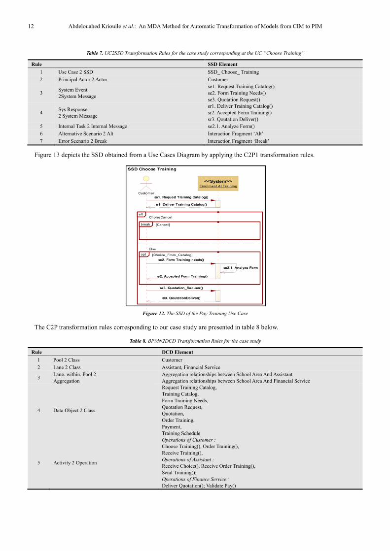
Table 7. UC2SSD Transformation Rules for the case study corresponding at the UC “Choose Training”
Rule SSD Element
1 Use Case 2 SSD SSD_ Choose_ Training
2 Principal Actor 2 Actor Customer
3 System Event
2System Message
se1. Request Training Catalog()
se2. Form Training Needs()
se3. Quotation Request()
4 Sys Response
2 System Message
sr1. Deliver Training Catalog()
sr2. Accepted Form Training()
sr3. Qoutation Deliver()
5 Internal Task 2 Internal Message se2.1. Analyze Form()
6 Alternative Scenario 2 Alt Interaction Fragment ‘Alt’
7 Error Scenario 2 Break Interaction Fragment ‘Break’
Figure 13 depicts the SSD obtained from a Use Cases Diagram by applying the C2P1 transformation rules.
Figure 12. The SSD of the Pay Training Use Case
The C2P transformation rules corresponding to our case study are presented in table 8 below.
Table 8. BPMN2DCD Transformation Rules for the case study
Rule DCD Element
1 Pool 2 Class Customer
2 Lane 2 Class Assistant, Financial Service
3 Lane. within. Pool 2
Aggregation
Aggregation relationships between School Area And Assistant
Aggregation relationships between School Area And Financial Service
4 Data Object 2 Class
Request Training Catalog,
Training Catalog,
Form Training Needs,
Quotation Request,
Quotation,
Order Training,
Payment,
Training Schedule
5 Activity 2 Operation
Operations of Customer :
Choose Training(), Order Training(),
Receive Training(),
Operations of Assistant :
Receive Choice(), Receive Order Training(),
Send Training();
Operations of Finance Service :
Deliver Quotation(); Validate Pay()
SSD Choose Training
se2.1. Analyze Form
sr3. QoutationDeliver()
se3. Quotation_Request()
sr1. Deliver Training Catalog()
se1. Request Training Catalog()
sr2. Accepted Form Training()
se2. Form Training needs()
Customer
<<System>>Enrolment At Training
ChoiseCancel
Else
alt
[Cancel]break
[Choice_From_Catalog]opt
se2.1. Analyze Form
sr3. QoutationDeliver()
se3. Quotation_Request()
sr1. Deliver Training Catalog()
se1. Request Training Catalog()
sr2. Accepted Form Training()
se2. Form Training needs()
American Journal of Software Engineering and Applications 2015; 4(1): 1-14 13
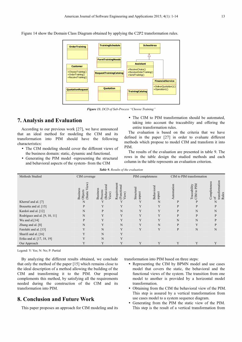
Figure 14 show the Domain Class Diagram obtained by applying the C2P2 transformation rules.
Figure 13. DCD of Sub-Process “Choose Training”
7. Analysis and Evaluation
According to our previous work [27], we have announced
that an ideal method for modeling the CIM and its
transformation into PIM should have the following
characteristics:
� The CIM modeling should cover the different views of
the business domain: static, dynamic and functional.
� Generating the PIM model -representing the structural
and behavioral aspects of the system- from the CIM
� The CIM to PIM transformation should be automated,
taking into account the traceability and offering the
entire transformation rules.
The evaluation is based on the criteria that we have
defined in the paper [27] in order to evaluate different
methods which propose to model CIM and transform it into
PIM.
The results of the evaluation are presented in table 9. The
rows in the table design the studied methods and each
column in the table represents an evaluation criterion.
Table 9. Results of the evaluation
Methods Studied CIM coverage PIM completeness CIM to PIM transformation
Bu
sines
s
Ob
ject
s
(Sta
tic
Vie
w)
Bu
sines
s
Pro
cess
(Beh
avio
ral
Vie
w)
Req
uir
emen
t
(Fu
nct
ion
al
Vie
w)
Str
uct
ura
l
aspec
t
Beh
avio
ral
aspec
t
Au
tom
atio
n
Tra
ceab
ilit
y
CIM
to
PIM
Co
mp
lete
nes
s
of
tran
sfo
rmat
ion
Rule
s
Kherraf and al. [7] N Y Y Y N P P N
Bousetta and al. [15] P Y Y Y Y P P P
Kardoš and al. [12] N P N Y Y P N N
Rodríguez and al. [9, 10, 11] N Y Y Y Y P P P
Wu and al.[14] P Y Y Y Y N N P
Zhang and al. [8] N Y N Y N P Y P
Fatolahi and al. [13] Y N Y Y Y P N N
Sharifi and al. [16] Y N Y
Erika and al. [17, 18, 19] Y N Y
Our Approach Y Y Y Y Y Y Y Y
Legend: Y: Yes; N: No; P: Partial
By analyzing the different results obtained, we conclude
that only the method of the paper [15] which remains close to
the ideal description of a method allowing the building of the
CIM and transforming it to the PIM. Our proposal
complements this method, by satisfying all the requirements
needed during the construction of the CIM and its
transformation into PIM.
8. Conclusion and Future Work
This paper proposes an approach for CIM modeling and its
transformation into PIM based on three steps:
� Representing the CIM by BPMN model and use cases
model that covers the static, the behavioral and the
functional views of the system. The transition from one
model to another is provided by a horizontal model
transformation.
� Obtaining from the CIM the behavioral view of the PIM.
This step is assured by a vertical transformation from
use cases model to a system sequence diagram.
� Generating from the PIM the static view of the PIM.
This step is the result of a vertical transformation from
Customer
+ChooseTraining()+OrderTraining()
+ReceiveTraining()
SchoolArea
TrainingCatalog
FinancialService
+DeliverQuotation()()
+Operation1()
Assistant
+ReceiveChoice()+ReceiveOrderTraining()
+SendTraining()
OrderTraining
Quotation
TrainingSchedule
RequestTrainingCatalog
FormTrainingNeeds
QuotationRequest
14 Abdelouahed Kriouile et al.: An MDA Method for Automatic Transformation of Models from CIM to PIM
BPMN model to a Domain Class Diagram.
In order to make transformations automatic, we have
developed all the transformation rules involved in this paper
using the QVT language.
Future works aim at developing a tool that supports all the
transformations performed in this paper.
References
[1] J. Miller and J. Mukerji, "MDA Guide Version 1.0.1.," OMG, 2003.
[2] R. Soley, «Model driven architecture (mda), draft 3.2. Rapport technique, disponible sur: http://www.omg.org/cgi-bin/doc?omg/00-11-05,» 2000.
[3] OMG, "Meta Object Facility (MOF)2.0 Query/View/Transformation Specification, http://www.omg.org/spec/QVT/1.0/PDF," 2009.
[4] S. A. White, "Introduction to BPMN," IBM Cooperation, pp. 2008-029, 2004.
[5] OMG, "OMG Unified Modeling LanguageTM (OMG UML), Superstructure, http://www.omg.org/spec/UML/2.4.1/Superstructure," August 2011.
[6] S. A. White, "Process Modelling Notations and Workflow Patterns, http://www.omg.org /bp-corner/bp-files/Process_Modeling_Notations.pdf," IBM Corporation, 2004.
[7] S. Kherraf, E. Lefebvre and W. Suryn, "Transformation from CIM to PIM Using Patterns and Archetypes," in 19th Australian Conference on Software Engineering, 2008.
[8] W. Zhang, H. Mei, H. Zhao and J. and Yang, "Transformation from CIM to PIM: A Feature-Oriented Component-Based Approach," in Model Driven Engineering Languages and Systems volume 3713 of Lecture Notes in Computer Science, pages 248–263, Springer Berlin / Heidelberg, 2005.
[9] A. Rodríguez, E. Fernández-Medina and M. Piattini, "Towards obtaining analysis-level class and use case diagrams from business process models," Advances in Conceptual Modeling–Challenges and Opportunities. Springer Berlin Heidelberg., pp. 103-112, 2008.
[10] A. Rodríguez, I. G.-R. de Guzmán, E. Fernández-Medina and M. Piattini, "Semi-formal transformation of secure business processes into analysis class and use case models: An mda approach," in Information and Software Technology, 52(9):945– 971, 2010.
[11] A. Rodríguez, E. Fernández-Medina, J. Trujillo and M. Piattini, "Secure business process model specification through a UML 2.0 activity diagram profile," Decision Support Systems, vol. 51, no. 3, pp. 446-465, 2011.
[12] M. Kardoš and M. Drozdová, "Analytical method of CIM to PIM transformation in Model Driven Architecture (MDA)," Journal Of Information And Organizational Sciences, vol. 34, pp. 89-99, 2010.
[13] A. Fatolahi, S. S. Somé and T. C. Lethbridge, "Towards a semi-automated model-driven method for the generation of web-based applications from use cases," in 4th Model Driven Web Engineering Workshop (p. 31), 2008.
[14] J. H. Wu, S. S. Shin, J. L. Chien, W. S. Chao and M. C. Hsieh, "An extended MDA method for user interface modeling and transformation," in The 15th European Conference on Information Systems (pp. 1632-1641)., June 2007.
[15] B. Bousetta, O. El Beggar and T. Gadi, "A methodology for CIM modelling and its transformation to PIM," Journal of Information Engineering and Applications, vol. 3, no. 2, pp. 1-21, 2013.
[16] H. R. Sharifi and M. Mohsenzadeh, "A New Method for Generating CIM Using Business and Requirement Models.," World of Computer Science and Information Technology Journal (WCSIT), vol. 2, no. 1, pp. 8-12, 2012.
[17] J. Osis, E. Asnina and A. Grave, "Computation Independent Modeling within the MDA," in Software-Science, Technology & Engineering, 2007. SwSTE 2007. IEEE International Conference on (pp. 22-34). IEEE, October 2007.
[18] J. Osis, E. Asnina and A. Grave, "Formal computation independent model of the problem domain within the MDA," in Proceedings of the 10th International Conference on Information System Implementation and Modeling (pp. 23-25), April 2007.
[19] J. Osis, E. Asnina and A. Grave, "Computation independent representation of the problem domain," in MDA. J. Software Eng, 2(1), 19-46., 2008.
[20] B. Xavier, MDA en Action : Ingénirie Logicielles Dirigée par les Modèles, Paris: Eyrolles, 2005.
[21] OMG, «Business Process Model and Notation (BPMN), Version 2.0.1,» OMG, http://www.omg.org/spec/BPMN, September 2013.
[22] OMG, "OMG Unified Modeling LanguageTM (OMG UML), Superstructure, http://www.omg.org/spec/UML/2.4.1/Superstructure," August 2011.
[23] OMG, «Semantics of Business vocabulary and Rules,» 2008. [En ligne].
[24] I. Jacobson, G. Booc et J. Rumbaugh, Le Processus unifié de développement logicie, Eyrolles, 2000.
[25] P. Kruchte, The rational Unified Process An introduction, Addison-WESLEY, 2000.
[26] A. Kriouile, T. Gadi, N. ADDAMSSIRI et A. El Khadimi, «Obtaining behavioral model of PIM from the CIM,» Multimedia Computing and Systems (ICMCS), 2014 International Conference on. IEEE, pp. 949-954., 2014.
[27] A. Kriouile, N. Addamssiri, T. Gadi et Y. Balouki, «Getting the Static Model of PIM from the CIM,» chez 3rd Colloquium IEEE on Information Science and Technology (CiSt'14), Tetuan, 2014.
[28] A. Kriouile, T. Gadi and Y. Balouki, "CIM to PIM Transformation: A criteria Based Evaluation," IJCTA, vol. Vol 4 (4), no. ISSSN:2229-6093, pp. 616-625, July-August 2013.