an investigation of arcing in the … · · 2017-12-15number at 64 f. p. s. were taken with...
TRANSCRIPT

EP-RR 22
AN INVESTIGATION OF ARCING IN THE ELECTROLYTIC SWITCH/TEST LOAD USED WITH THE CANBERRA HOMOPOLAR GENERATOR
B. D. SMITH
October, 1969
HANCOCK
Department of Engineering Physics
Research School of Physical Sciences
THE AUSTRALIAN NATIONAL UNIVERSITY
Canberra, A.C.T., Australia.
f T J 163 . AST EP-^R22
TJ163.A87 EP-RB22.1 9 2 4 1 4 4
A . N . U . L I B R A R Y

This book was published by ANU Press between 1965–1991.
This republication is part of the digitisation project being carried out by Scholarly Information Services/Library and ANU Press.
This project aims to make past scholarly works published by The Australian National University available to
a global audience under its open-access policy.

AN INVESTIGATION OF ARCING IN THE
ELECTROLYTIC SWITCH/TEST LOAD USED WITH THE
CANBERRA HOMOPOLAR GENERATOR
by
B. D. SMITH
October, 1969
Publication EP-RR 22
Department of Engineering Physics Research School of Physical Sciences
THE AUSTRALIAN NATIONAL UNIVERSITY
Canberra, A. C. T. Australia

2 8 SE

CONTENTS
Page
Summary iii
1. Introduction 1
2. Experim ental A rrangem ent 1
3. R esults 33 .1 A rcing Depth3. 2 Operation as a C ircuit B reaker3 .3 Arc Initiation High Speed Photographs
4. Baffle P late T ests 84 .1 Purpose and Equipment4 .2 Test
5. Conclusions 10
ii

SUMMARY
The E lectro lytic Sw itch/Test Load used with the
C anberra Homopolar G enerator had, over a num ber of0
y ears successfu lly in terrup ted cu rren ts of over 10 am ps,
but on one occasion during an unusual operating mode,
arced and failed to break a cu rren t of le ss than 20, 000 amps.
Subsequent investigation showed that there a re well
defined conditions under which such a failure w ill occur and
that these can be defined m ost conveniently in te rm s of a
single p a ram e te r, a c ritic a l depth of im m ersion . Operating
the switch with a full im m ersion le ss than th is depth will
re su lt in alm ost certa in failure while conversely, a depth
reasonably in excess of th is c ritic a l value w ill ensure the
safe operation.
iii

1 . INTRODUCTION
The investigation reported here was undertaken because of anom alous behaviour of the e lec tro ly tic switch used with the C anberra Homopolar G enerator. This variab le re s is to r /sw itc h , which has consistently over a num ber of years controlled and broken cu rren ts of over 10® am ps, on one occasion a rced and failed to b reak a cu rren t of le ss than 20,000 amps under a condition of extrem ely sm all in itia l p la te im m ersion . (See R eport EP-RR 23)
The s e r ie s of te s ts repo rted herein was designed to investigate the c h a rac te ris tic s of a rc ing from two approaches. The f i r s t p a rt established experim enta lly the conditions under which arcing is likely to occur between the e lectrode p la tes, as a function of sev era l variab les. To th is end, over 500 operations w ere reco rd ed under varying conditions - with just under half resu lting in a rc s .
The v ariab les considered were:(i) Depth of Im m ersion of p lates(ii) Speed of operation of the switch in te rm s of angular velocity of
the driv ing cam.(iii) Open c irc u it volts applied(iv) C urren t c a rrie d(v) E lec tro ly te re s is tiv ity
The geom etry of the switch was fixed nam ely, 4 anode p lates with 3 in te rleaved cathode p la tes , and all the calibration runs w ere done with one polarity .
The second p a r t of the investigation was to determ ine the m echanism of a rc in itia tion , Four high speed film s at 3000 fram es p er second (f. p. s . ) and a num ber a t 64 f. p. s. w ere taken with sim ultaneous voltage, cu rren t and tank po sition reco rd s . This section also included com parative m easurem ents for opposite p o la ritie s in the asy m etrica l switch used, and the testing of a sim ple method of a rc suppression .
2. EXPERIMENTAL ARRANGEMENT
The m ain power c ircu it (F igure 1) consisted of a 500 volt, 400 kW d .c . generato r set and a 1-D- w atercooled b a lla st re s is to r in s e r ie s with the e lectro ly tic switch. An additional 0 - 4 -A. variab le re s is to r was included in the c ircu it and a shunt contactor was used to te rm ina te the a rc soon a fte r initiation, so as to m inim ise damage to the p lates.
1

EXPERIMENTAL ARRANGEMENT 2
-WWW0 - LSI
400
500
blpl
- wwvFigure 1 Power C ircuit
ElectrolyticSwitch
The elec tro ly tic switch used was a section of the main T est Load. Seven adjacent p la tes at one co rner w ere enclosed in a sm all tank fitted inside the main T est Load tank (figure 2). This sm all tank contained the e lectro ly te under te st, while the m ain body of the T est Load tank was filled with w ater as ballast.The level of the w ater was such that it did not wet the unused p lates so that the total cu rren t m easured was in fact passing through the e lectro ly te.
+ - - 4- - +
Pla te s
1"
(b) End view
(a) Side view of p la te . Only unshaped section used.
Tank
Figure 2 Showing construction of the e lec tro ly tic switch used in the te s ts .
An u ltrav io le t ch art re c o rd e r was used to take concurrent re co rd s of:-
(i) Voltage a c ro ss the electrode p la tes(ii) C urrent(iii) Tank position(iv) — for each of the seven plates
dt
This la s t was m easured as the output of seven Rogowski belts, one to each plate , and served as an indication of cu rren t change in the individual p la tes.
The cu rren t and voltage w ere m easured with galvam om eters having a flat response up to 1200 cycles/second while the o ther reco rd s w ere made with 50 cycle/second galvam om eters.

3. 3. 1
RESULTS A rcing Depth
3
It becam e evident fa irly early in the tr ia ls that the m ost convenient p a ram ete r in which to m easure the likelihood of a rc ing was the depth to which the p la tes w ere im m ersed in the electro lyte. If all o ther conditions rem ain constant, th e re is a fa irly well defined depth of im m ersion above which arcing will not occur and below which it will occur. This depth is called here the "arcing depth". As will be seen in the next section (3. 2) if we wish to define a com pletely safe region we m ust exclude a band of depths of which the "arc ing depth" is the lower lim it.
The arcing depth is dependent on all the other variab les considered and the re su lts of this section have been presen ted as a set of graphs, showing arcing depth as a function of each of the other variab les , while holding the rem aining ones constant. (See F igures 3, 4 and 5)
55
£
Hi
Hi
/O 4-
c c ' # 4 £ / v r ~ /IM P S
F igure 3 Arcing depth shown as a function of full im m ersion cu rren t.

AR
CIN
G D
EPTH
, m
.ms.
A
RC
ING
D
EPTH
, m
.ms.
RESULTS 4
F igure 4 A rcing depth shown as a function of open c ircu it voltage applied.
C m s480 ,
O t f ‘6
□ 33-4470
Voc - 500 v Current shown
o e 09 CAM SPEED
F igure 5 Arcing depth shown as a function of speed of operation.

RESULTS 5
D efinitions:
(i) C u rren t: F igu res given for cu rren t re fe r to total cu rren t flowing throughall p la tes i. e. 3 cathode and 4 anode plates.
(ii) A rcing depth: The deepest im m ersion for which arcing would occurunder the specified conditions. It was generally determ ined as the mean of two depths 2 mm. ap art, such that the lower arced and the upper did not.
(iii) V olts: m easu red across the electrode plates
(iv) Speed; This is proportional to the angular velocity of the cam . 1. 00 corresponds to tank movement cycle of 1 .1 sec. period (approxim ately sine wave).
3. 2 Operation as a C ircuit B reaker
R ecords of cu rren t against tim e and tank position, show that the switch continues to conduct an appreciable cu rren t even afte r the e lectro ly te has fallen below the bottom of the electrode p lates. This is due to s tream s of electro ly te running off the p late , continuing to provide a cu rren t path.
F igure 6 Photograph showing F igure 7 Photograph showingelec tro ly te s tream s s tream s exploding,from plates.
In fact the ability of the electolytic switch to ’’break" large cu rren ts depends on these s tream s which m ust be m aintained until th e ir increasing re s is tan ce im plies a re la tive ly sm all cu rren t.

RESULTS 6
In figure 8 we see typical cu rren t vs, tim e curves for various depths of im m ersion.
electrolytesurface
50m. Sec./ Div.
Deep Im m ersion. Im m ersed le ss thanarching depth.
F igure 8 T racings of reco rd showing cu rren t vs. tim e ch a rac te ris tic s for deep and shallow im m ersion .
F igure 8 (a) is a typical cu rren t curve as the p lates a re withdrawn from an im m ersion well in excess of the arcing depth. The f ir s t downward curve rep re sen ts the increasing re s is tan ce as the depth of p late im m ersed in the e lectro ly te becom es sm all. A fter the surface has fallen below the bottom of the p la tes, the e lectro ly te s tream s rem ain intact; at leas t until no m easurable cu rren t re m a in s , e. g. with 60 m illim eters im m ersion under conditions giving an arc ing depth of 4 mm, the s tream s w ere s till in tact at 40 mm. length when the cu rren t was v irtually zero.
A rcing was never observed in conjunction with th is curve, and fu rther, once th is form of curve appeared, all deeper im m ersions under the sam e conditions, produced the sam e form of curve.
F igure 8 (c) is a typical cu rren t curve for an im m ersion n ear or below the arcing depth. P a r t of the way down, the e lectro ly te s tream rup tu res and the cu rren t drops suddenly. The shallow er the im m ersion , the higher is the break point and the m ore likely is the p ro cess to develop to an a rc . Except in the case of very shallow im m ersion (1 or 2 m m .) w here arcing resu lted from contact ra th e r than separation, an a rc was always preceeded by th is break in the cu rren t curve.

RESULTS 7
This rup tu re of the s tream s is quite evident on photographs taken with im m ersion near or within the arcing range - F igure 7. The b reak occurred at the end of the s tream in contact with the electrode p lates - in th is instance the tn ree cathode p lates. Howeveq on rev e rs in g the po larity it was s till the th ree even- num bered s tream s, th is tim e from the anode p lates, which broke, suggesting it was due to the g re a te r cu rren t density in these p lates. The curve of F igure 8 (b) is for an in term ediate im m ersion , and could be regarded as a lim iting case of figure 8 (c) w here the b reak is very close to zero cu rren t.
An example of the re la tive depths involved for the different fo rm s of cu rren t curve, we have the following experim ental re su lts :
24.4 ohm cm electro ly te, 500 volts, 450 amps (i. e. 150 a m p s / cathode plate) 1. 00 cam speed
Depths from 38 mm. gave curves of type (a), while a t 23 mm. im m ersion, the graph assum ed form (b). At 16 mm. , a definite in c rease in slope appeared at 100 am ps which, by 12 m m ., becam e a com plete b reak at 110 am ps. Im m ersion of 11 mm. produced a b reak at 140 A, resu lting in an a rc .
3. 3 A rc Initiation - High Speed Photographs
Four high speed film s, (3000 fram es/second) two of each po larity , w ere taken and show the a rc starting . In each case, it s ta r ts as a point of light a t the tip of a cathode plate , and stays typically 2 - 3 m illiseconds in th is form before strik ing a c ro ss to the adjacent anode plate. At th is stage the cu rren t is re la tive ly low and the voltage h ig h , e. g. in a typical reco rd at th is stage, the cu rren t is ~ 45 am ps with the voltage from 445 - 490 Volts. Assum ing that m ost of
*«
t o % '
Figure 9 Ten consecutive fram es (negative) at 3000 p .p . s . , showing the a rc initiating as a spot a t a cathode plate and developing into an a rc to an anode p la te . Sequence righ t to left, top row f ir s t .

RESULTS 8
the inter electrode voltage drop occurs across this spot, it fits the characteristics of a glow discharge.
The tim e spent in this form can vary greatly from the Typical 2 - 3 msec; delays of 25 m sec have appeared on some records while others show a delay too sm all to be measured accurately from the chart ( < J msec)
Changing polarity in this case, moved the initiating point from an even numbered plate to an odd numbered plate, i. e. , the arc insisted on starting from a cathode plate. Changing only the polarity, increased the minimum total current required for arcing from 300 amps with 3 cathode plates, to 400 amps for 4 cathode plates: this seem s to suggest that the current density in the cathode plates is the relevant constant. It is not immediately obvious how this fits in with the earlier evidence that it is the higher current density stream that breaks first, irrespective of polarity.
The photographs also showed that arcing can occur on entry of the plates into the electrolyte. Of the 4 high speed film s taken, the distinctive cathode spot appears on three at the tim e of entry. One of these develops into an arc between two plates and lasts about 10 m sec before being quenched by reduced voltage drop as the electrolyte level r ise s . This contact arc appears on several of the recorder charts, and becom es evident for very shallow im m ersions when the arc does not extinquish.
4. BAFFLE PLATE TESTS
4 .1 On a suggestion from Mr P. O. Carden* insulating plates were triedbetween the electrode plates as a method of preventing arcing between them. The intended function of the baffle plates was two-fold.
(i) To increase the current path length, and so the resistance, in the latter stages of withdrawal, before the plates leave the surface.
(ii) To provide a physical barrier to arcing, at least for a few inches up from the bottom of the plates.
Both these actions were evident in the resu lts, and the technique proved very successful, providing some further confirmatory information on the arc initiation.
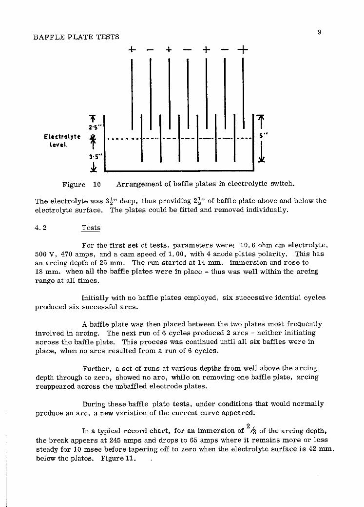
The baffle plates used were strips of eighth inch bakelite, 5” deep and the full lenth of the electroltye tank (24”) extending 3" past the electrode plates at one end, and 9” at the other. They were level with the top of the electrolyte tank and came to within 1** of the bottom of the tank. Figure 10.
* Magnet Laboratory, Department of Engineering Physics
BAFFLE PLATE TESTS9
Electrolytelevel
Figure 10 A rrangem ent of baffle p la tes in e lectro ly tic switch.
The electro ly te was 3^" deep, thus providing 2^" of baffle plate above and below the e lectro ly te surface. The p lates could be fitted and rem oved individually.
4 .2 T ests
For the f ir s t se t of te s ts , p a ram ete rs were: 10. 6 ohm cm electro ly te, 500 V, 470 am ps, and a cam speed of 1. 00, with 4 anode plates polarity . This has an arcing depth of 25 mm. The run s ta rted at 14 mm. im m ersion and ro se to 18 mm. when all the baffle p la tes w ere in place - thus was well within the arcing range at all tim es.
Initially with no baffle p la tes employed, six successive idential cycles produced six successful a rc s .
A baffle plate was then placed between the two p lates m ost frequently involved in arcing. The next run of 6 cycles produced 2 a rc s - ne ither initiating a c ro ss the baffle plate. This p ro cess was continued until all six baffles w ere in p lace, when no a rc s resu lted from a run of 6 cycles.
F urther, a set of runs at various depths from well above the arcing depth through to zero , showed no a rc , while on rem oving one baffle p late , arcing reappeared acro ss the unbaffled electrode p lates.
During these baffle p la te te s ts , under conditions that would norm ally produce an a rc , a new variation of the cu rren t curve appeared.
In a typical re co rd chart, for an im m ersion of 2 /% of the a rc ing depth, the b reak appears a t 245 am ps and drops to 65 amps where it rem ains m ore or le ss steady for 10 m sec before tapering off to zero when the electro ly te surface is 42 mm. below the plates. Figure 11.

BAFFLE PLATE TESTS 10
Lt-Plites I leave 1 electrolyte i! surface
50m.Sec./ Div.
Figure 11 T racing of cu rre n t c h a rac te ris tic with baffle p lates in and im m ersion of tw o-th irds arcing depth.
This corresponds well with the cathode glow stage that appears before every a rc , but apparently the baffle plate p reven ts the a rc strik ing to the adjacent anode plate.
5. CONCLUSIONS
F rom the curves of F igures 3 ,4 , 5, it is evident that under any c ircum stances a deep im m ersion is much le ss likely to re su lt in an a rc and that below som e c ritic a l im m ersion depth, arcing is v irtually certain . On the other hand, an im m ersion deep enough to produce a smooth cu rren t curve of the form in figure 8 (a) will not a rc . F o r the sm all num ber of te s ts that covered the full range (three), th is ’’safe" curve appeared at about twice the arcing depth.
F o r the conditions under which the original fa ilu re occurred , the arcing depth was about 25 m m ., so that the safe region could be expected at no le ss than 50 mm. With th is in mind, the actual im m ersion of 54 mm. could be considered uncom fortably close, allowing no m argin for uneven cu rren t d istribution acro ss the switch or any ir re g u la r it ie s in operation.
Many variab les a re involved, and it is difficult from the somewhat lim ited scope of the investigation to p red ic t the behaviour of an electro ly tic switch under specified c ircum stances. However it can be said that a tendancy to a rc lies

CONCLUSIONS 11
in the following direction:
(i) Shallow im m ersion(ii) High cu rren t densities(iii) Low elec tro ly te re s is tiv itie s(iv) Slow operation of the switch(v) High voltage
N orm al operating requ irem en ts will generally n ecessita te som e of these conditions, but safe operation could be insured by allowing sufficient m argin in the u n re s tric ted te rm s . The final te s t of satisfac to ry and safe operation is a smooth cu rren t c h a rac te ris tic of the form in figure 8 (a).
(b) The baffle p la tes proved a very effective method of preventing an incipient a rc from strik ing , and of reducing the tendency to a rc , so long as all w ere in place.
(c) In view of the evidence that the a rc m ust s ta r t a t the cathode, it would have been in te restin g to see what would happen if the cathode p la tes w ere made somewhat longer than the anode p la tes so that the b reak would occur at the anode, while the cathode is s till im m ersed . This, of course im plies a single po larity c ircu it b reak er. This was not examined because of tim e lim itations.

R I
P ub lications by D epartm en t of E ngineering P h y sics
No._________ A uthor
E P -R R 1 H ibbard, L. U.
E P -R R 2 C arden , P . O.
E P -R R .3 M arshall, R. A.
E P -R R 4 M arshall, R. A.
E P -R R 5 Inall, E. K.
E P -R R 6 Inall, E.K.
E P -R R 7 Inall, E. K.
E P -R R 8 B rady, T.W.
E P -R R 9 Inall, E.K.
T itle
C em enting R o to rs fo r the C a n b e rra H om opolar G en era to r
L im ita tions of R ate of R ise of P u lse C u rre n t Im posed by Skin E ffect in R o to rs
The D esign of B ru sh es fo r the C an b e rra H om opolar G en e ra to r
The E lec tro ly tic V ariab le R es is ta n ce T e s t Load/Sw itch fo r the C a n b e rra H om opolar G en e ra to r
The M ark II Coupling and R o to r C en tering R e g is te rs fo r the C a n b e rra Hom opo- l a r G en era to r
A Review of the S pecifications and D esign of the M ark II Oil L ubricated T h ru s t and C en tering B earin g s of the C an b e rra H om opolar G en era to r
P ro v in g T e s ts on the C a n b e rra H om opolar G ene r a to r w ith the Two R oto rs Connected in S e rie s
Notes on Speed B alance C on tro ls on the C an b erra H om opolar G en era to r
T e s ts on the C an b erra H om opoiai G en era to r A rran g ed to Supply the 5 M egaw att M agnet
F ir s tP u b lished R e -issu ed
May, 1959 A pril, 1967
Sept., 1962 A pril, 1967
Ja n ., 1964 A pril, 1967
May, 1964 A pril, 1967
Oct. , 1964 A pril, 1967
Nov. , 1964 A pril, 1967
F e b . , 1966 A pril, 1967
M ar. ,1966 A pril, 1967
May, 1966 A pril, 1967

P u b lic a tio n s by D epartm en t of E ngineering P h y s ic s (C o n t.) R2
No. A uthor T itleF i r s t
Pub lished
E P -R R 10 B rady, T .W . A Study of the P e rfo rm a n c e of the 1000 kW M otor G ene ra to r Set Supplying the C an b erra H om opolar G ene ra to r F ield
June, 1966
E P -R R 11 M acleod, I.D.G. In stru m en ta tio n and C ontrolof the C an b erra H om opolar G en era to r by O n-L ine C om p u te r
O c t . , 1966
E P -R R 12 C arden , P .O . M echanical S tre s s e s in anInfin itely Long Homogeneous B it te r Solenoid w ith F in ite E x terna l Field
Jan . , 1967
E P -R R 13 M acleod, I.D.G. A Survey of Iso la tion A m pli- Feb. , 1967f ie r C irc u its
E P -R R 14 Inall, E .K . The M ark III Coupling fo r the R o to rs of the C an b erra H om opolar G en era to r
E P -R R 15 B ydder, E. L. On the In teg ra tion of L iley , B .S . "B o ltzm ann-L ike"
C ollision In teg ra ls
E P -R R 16 Vance, C . F . Sim ple T h y r is to r C irc u itsto P u ls e -F ir e Ign itrons fo r C apac ito r D ischarge
E P -R R 17 B ydder, E. L. On the E valuation of E las ticand In e la s tic C ollision F r e quencies fo r H ydrogen ic-L ike P la sm a s
F e b . ,1967
M ar. ,1967
M ar. ,1967
Sept. ,1967
E P -R R 18 S tebbens, A.W ard, H.
The D esign of B ru sh es fo r the H om opolar G en era to r a t The A u stra lian N ational U niversity
M ar. ,1964
R e-issu ed
A pril, 1967
A pril, 1967
S e p t. , 1967

Publications by D epartm ent of Engineering P hysics (Cont.) R3
No. AuthorF irs t
T itle Published R e-issued
EP-R R 19 Carden, P . O. F eatures of the High F ield J a n . , 1967Magnet Laboratory a t the A ustralian National U niversity, C anberra
EP-RR 20 Kaneff, S.Vladcoff, A. N.
Self-Organizing teaching Dec. ,1968Systems
EP-RR 21 Vance, C. F. Microwave Pow er tra n s - Feb. ,1969m ission Ratio: Its Usein Estim ating E lectron Density
EP-RR 22 Smith, B. D. An Investigation of Arcing Oct. ,1969in the E lectro ly tic Sw itch/T est Load Used with the Homopolar G enerator
EP-R R 23 Inall, E. K. Use of the Homopolar M ar. ,1969G enerator to Pow er Xenon D ischarge Tubes and som e A ssociated Switching Problem s
EP-R R 24 Carden, P . O. Pivoted H ydrostatic Dec. ,1969Bearing Pads for the C anberra Homopolar G enerator
EP-R R 25 Carden, P .O .Whelan, R. E.
Instrum entation for the D e c ., 1969A ustralian National U niversity 300 kilogauss Experim ental Magnet
Copies of this Department of
Price: $A1.00 Copyright Note:
&
and other Publications (see list inside) of the Engineering Physics may be obtained from:
The Australian National University Press, P.O. Box 4, Canberra, A.C.T., 2600. Australia.
Reproduction of this publication in whole or in part is not allowed without prior permission. It may however be quoted as a reference.
National Library of Australia Card Number and ISBN 0 85584 002 1